1
1
Toshiba Personal Computer
Satellite A50S/TECRA A3X Series
Maintenance Manual
TOSHIBA CORPORATION
File Number 960-534
[CONFIDENTIAL]
Copyright
© 2005 by Toshiba Corporation. All rights reserved. Under the copyright laws, this manual cannot be
reproduced in any form without the prior written permission of Toshiba. No patent liability is assumed with
respect to the use of the information contained herein.
Toshiba Satellite A50S/TECRA A3X Series Maintenance Manual
First edition September 2005
Disclaimer
The information presented in this manual has been reviewed and validated for accuracy. The included set of
instructions and descriptions are accurate for the Satellite A50S/TECRA A3X series at the time of this manual's
production. However, succeeding computers and manuals are subject to change without notice. Therefore,
Toshiba assumes no liability for damages incurred directly or indirectly from errors, omissions, or discrepancies
between any succeeding product and this manual.
Trademarks
Intel, Intel SpeedStep, Pentium and Celeron are trademarks or registered trademarks of Intel Corporation or its
subsidiaries in the United States and other countries/regions.
Windows and Microsoft are registered trademarks of Microsoft Corporation.
Other trademarks and registered trademarks not listed above may be used in this manual.
ii
[CONFIDENTIAL]
Satellite A50S/TECRA A3X Maintenance Manual (960-534)
Preface
This maintenance manual describes how to perform hardware service maintenance for the
Toshiba Personal Computer Satellite A50S/TECRA A3X series.
NOTE: This Satellite A50S/TECRA A3X series is a BTO-support personal computer.
Each model has a different configuration. For each model’s configuration, refer to the
parts list dedicated to it.
The procedures described in this manual are intended to help service technicians isolate
faulty Field Replaceable Units (FRUs) and replace them in the field.
SAFETY PRECAUTIONS
Four types of messages are used in this manual to bring important information to your
attention. Each of these messages will be italicized and identified as shown below.
DANGER: “Danger” indicates the existence of a hazard that could result in death or
serious bodily injury, if the safety instruction is not observed.
WARNING: “Warning” indicates the existence of a hazard that could result in bodily
injury, if the safety instruction is not observed.
CAUTION: “Caution” indicates the existence of a hazard that could result in property
damage, if the safety instruction is not observed.
NOTE: “Note” contains general information that relates to your safe maintenance
service.
Improper repair of the computer may result in safety hazards. Toshiba requires service
technicians and authorized dealers or service providers to ensure the following safety
precautions are adhered to strictly.
? Be sure to fasten screws securely with the right screwdriver. Be sure to use the PH
Point size “0” and “1” screwdrivers complying with the ISO/DIS 8764-1:1996. If a
screw is not fully fastened, it could come loose, creating a danger of a short circuit,
which could cause overheating, smoke or fire.
? If you replace the battery pack or RTC battery, be sure to use only the same model
battery or an equivalent battery recommended by Toshiba. Installation of the wrong
battery can cause the battery to explode.
Satellite A50S /TECRA A3X Maintenance Manual (960-534)
[CONFIDENTIAL]
iii
The manual is divided into the following parts:
Chapter 1
Hardware Overview describes Satellite A50S/TECRA A3X series
system unit and each FRU.
Chapter 2
Troubleshooting Procedures explains how to diagnose and resolve
FRU problems.
Chapter 3
Test and Diagnostics describes how to perform test and diagnostic
operations for maintenance service.
Chapter 4
Replacement Procedures describes the removal and replacement of the
FRUs.
Appendices
The appendices describe the following:
?
?
?
?
?
?
?
?
iv
Handling the LCD module
Board layout
Pin assignment
Display codes
Key layout
Wiring diagrams
BIOS/KBC/EC Update
Reliability
[CONFIDENTIAL]
Satellite A50S/TECRA A3X Maintenance Manual (960-534)
Conventions
This manual uses the following formats to describe, identify, and highlight terms and
operating procedures.
Acronyms
On the first appearance and whenever necessary for clarification acronyms are enclosed in
parentheses following their definition. For example:
Read Only Memory (ROM)
Keys
Keys are used in the text to describe many operations. The key top symbol as it appears on
the keyboard is printed in boldface type.
Key operation
Some operations require you to simultaneously use two or more keys. We identify such
operations by the key top symbols separated by a plus (+) sign. For example, Ctrl + Pause
(Break) means you must hold down Ctrl and at the same time press Pause (Break). If
three keys are used, hold down the first two and at the same time press the third.
User input
Text that you are instructed to type in is shown in the boldface type below:
DISKCOPY A: B:
The display
Text generated by this computer that appears on its display is presented in the type face
below:
Format complete
System transferred
Satellite A50S /TECRA A3X Maintenance Manual (960-534)
[CONFIDENTIAL]
v
Table of Contents
Chapter 1
Hardware Overview
1.1
Features ...................................................................................................................... 1-1
1.2
System Block Diagram .............................................................................................. 1-6
1.3
3.5-inch USB Floppy Disk Drive ............................................................................. 1-10
1.4
2.5-inch Hard Disk Drive......................................................................................... 1-11
1.5
CD-ROM Drive ........................................................................................................ 1-13
1.6
DVD-ROM Drive .................................................................................................... 1-15
1.7
DVD-ROM & CD-R/RW Drive .............................................................................. 1-18
1.8
DVD Super Multi Drive........................................................................................... 1-21
1.9
Keyboard .................................................................................................................. 1-24
1.10
TFT Color Display................................................................................................... 1-25
1.11
Power Supply ........................................................................................................... 1-28
1.12
Batteries ................................................................................................................... 1-30
1.13
AC Adapter .............................................................................................................. 1-33
Chapter 2
Troubleshooting Procedures
2.1
Troubleshooting ......................................................................................................... 2-1
2.2
Troubleshooting Flowchart........................................................................................ 2-2
2.3
Power Supply Troubleshooting.................................................................................. 2-6
2.4
System Board Troubleshooting................................................................................ 2-15
2.5
3.5” FDD Troubleshooting ...................................................................................... 2-29
2.6
2.5” HDD Troubleshooting...................................................................................... 2-32
2.7
Keyboard Troubleshooting ...................................................................................... 2-37
2.8
Display Troubleshooting.......................................................................................... 2-38
2.9
Touch Pad Troubleshooting ..................................................................................... 2-41
2.10
Optical Drive Troubleshooting ................................................................................ 2-42
2.11
Modem Troubleshooting.......................................................................................... 2-43
2.12
LAN Troubleshooting .............................................................................................. 2-44
vi
[CONFIDENTIAL]
Satellite A50S/TECRA A3X Maintenance Manual (960-534)
2.13
Sound Troubleshooting ............................................................................................ 2-45
2.14
Wireless LAN Troubleshooting ............................................................................... 2-47
Chapter 3
Tests and Diagnostics
3.1
The Diagnostic Test ................................................................................................... 3-1
3.2
Executing the Diagnostic Test ................................................................................... 3-4
3.3
Setting of the hardware configuration........................................................................ 3-8
3.4
Heatrun Test ............................................................................................................. 3-11
3.5
Subtest Names.......................................................................................................... 3-12
3.6
System Test.............................................................................................................. 3-14
3.7
Memory Test............................................................................................................ 3-16
3.8
Keyboard Test.......................................................................................................... 3-17
3.9
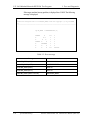
Display Test ............................................................................................................. 3-18
3.10
Floppy Disk Test ...................................................................................................... 3-21
3.11
Printer Test ............................................................................................................... 3-23
3.12
Async Test................................................................................................................ 3-25
3.13
Hard Disk Test ......................................................................................................... 3-26
3.14
Real Timer Test........................................................................................................ 3-29
3.15
NDP Test.................................................................................................................. 3-31
3.16
Expansion Test ......................................................................................................... 3-32
3.17
CD-ROM/DVD-ROM Test ..................................................................................... 3-34
3.18
Error Code and Error Status Names......................................................................... 3-35
3.19
Hard Disk Test Detail Status .................................................................................... 3-38
3.20
ONLY ONE TEST................................................................................................... 3-40
3.21
Head Cleaning.......................................................................................................... 3-46
3.22
Log Utilities ............................................................................................................. 3-47
3.23
Running Test............................................................................................................ 3-49
3.24
Floppy Disk Drive Utilities...................................................................................... 3-50
3.25
System Configuration .............................................................................................. 3-55
3.26
Wireless LAN Test Program (Intel- made b/g) ......................................................... 3-57
3.27
Wireless LAN Test Program (Intel- made a/b/g)...................................................... 3-61
3.28
Wireless LAN Test Program (Askey- made) ............................................................ 3-66
Satellite A50S /TECRA A3X Maintenance Manual (960-534)
[CONFIDENTIAL]
vii
3.29
LAN/Modem/Bluetooth/IEEE1394 Test Program .................................................. 3-70
3.30
Sound Test program................................................................................................. 3-84
3.31
SETUP ..................................................................................................................... 3-90
Chapter 4
Replacement Procedures
4.1
Overview .................................................................................................................... 4-1
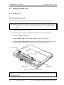
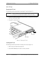
4.2
Battery Pack/PC Card ................................................................................................ 4-8
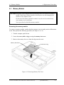
4.3
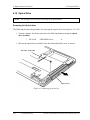
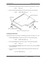
Memory Module ...................................................................................................... 4-11
4.4
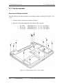
MDC......................................................................................................................... 4-14
4.5
HDD......................................................................................................................... 4-16
4.6
Wireless LAN Card.................................................................................................. 4-19
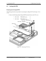
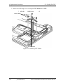
4.7
Cooling Fin/CPU ..................................................................................................... 4-21
4.8
Keyboard .................................................................................................................. 4-26
4.9
Switch Membrane Board ......................................................................................... 4-30
4.10
Optical Drive............................................................................................................ 4-32
4.11
Display Assembly .................................................................................................... 4-34
4.12
Sound Board............................................................................................................. 4-38
4.13
Parallel port board/Serial port board/S-Video board ............................................... 4-39
4.14
FAN.......................................................................................................................... 4-46
4.15
System Board/DC-IN Jack/RTC Battery................................................................. 4-47
4.16
PC card cover........................................................................................................... 4-50
4.17
Battery Latch............................................................................................................ 4-51
4.18
Battery Lock............................................................................................................. 4-53
4.19
Touch Pad ............................................................................................................... 4-55
4.20
LCD Unit/FL Inverter .............................................................................................. 4-57
4.21
Latch Assembly........................................................................................................ 4-61
4.22
Wireless LAN Antenna/Speaker/Hinge ................................................................... 4-62
4.23
Fluorescent Lamp ..................................................................................................... 4-71
Appendices
Appendix A
Handling the LCD Module ........................................................................ A-1
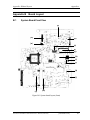
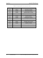
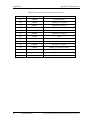
Appendix B
Board Layout ...............................................................................................B-1
viii
534)
[CONFIDENTIAL]
Satellite A50S/TECRA A3X Maintenance Manual (960-
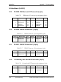
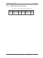
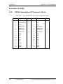
Appendix C
Pin Assignment .......................................................................................... C-1
Appendix D
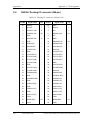
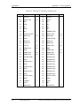
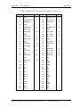
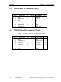
Keyboard Scan/Character Codes ............................................................... D-1
Appendix E
Key Layout ..................................................................................................E-1
Appendix F
Wiring Diagrams.........................................................................................F-1
Appendix G
BIOS/KBC/EC Update .............................................................................. G-1
Appendix H
Reliability................................................................................................... H-1
Satellite A50S /TECRA A3X Maintenance Manual (960-534)
[CONFIDENTIAL]
ix
x
[CONFIDENTIAL]
Satellite A50S/TECRA A3X Maintenance Manual (960-534)
Chapter 1
Hardware Overview
[CONFIDENTIAL]
1 Hardware Overview
1
1-ii
Hardware Overview
[CONFIDENTIAL]
Satellite A50S/TECRA A3X Maintenance Manual (960-534)
1 Hardware Overview
Chapter 1
Contents
1.1
Features ...................................................................................................................... 1-1
1.2
System Block Diagram .............................................................................................. 1-6
1.3
3.5-inch USB Floppy Disk Drive ............................................................................. 1-10
1.4
2.5-inch Hard Disk Drive......................................................................................... 1-11
1.5
CD-ROM Drive ........................................................................................................ 1-13
1.6
DVD-ROM Drive .................................................................................................... 1-15
1.7
DVD-ROM & CD-R/RW Drive .............................................................................. 1-18
1.8
DVD Super Multi Drive........................................................................................... 1-21
1.9
Keyboard .................................................................................................................. 1-24
1.10
TFT Color Display................................................................................................... 1-25
1.10.1
LCD Module........................................................................................ 1-25
1.10.2
FL Inverter Board ................................................................................ 1-27
1.11
Power Supply ........................................................................................................... 1-28
1.12
Batteries ................................................................................................................... 1-30
1.13
1.12.1
Main Battery........................................................................................ 1-30
1.12.2
Battery Charging Control .................................................................... 1-31
1.12.3
RTC Battery......................................................................................... 1-32
AC Adapter .............................................................................................................. 1-33
Satellite A50S/TECRA A3X Maintenance Manual (960-534)
[CONFIDENTIAL]
1-iii
1 Hardware Overview
Figures
Figure 1-1
Front of the computer..................................................................................... 1-4
Figure 1-2
System units configuration ............................................................................ 1-5
Figure 1-3
System block diagram.................................................................................... 1-6
Figure 1-4
3.5-inch USB FDD....................................................................................... 1-10
Figure 1-5
2.5-inch HDD............................................................................................... 1-11
Figure 1-6
CD-ROM Drive ............................................................................................ 1-13
Figure 1-7
DVD-ROM Drive ........................................................................................ 1-15
Figure 1-8
DVD-ROM & CD-R/RW Drive .................................................................. 1-18
Figure 1-9
DVD Super Multi Drive............................................................................... 1-21
Figure 1-10
Keyboard ...................................................................................................... 1-24
Figure 1-11
LCD module................................................................................................. 1-25
Tables
Table 1-1
3.5-inch USB FDD specifications ................................................................ 1-10
Table 1-2
2.5-inch HDD dimensions ........................................................................... 1-11
Table 1-3
2.5-inch HDD specifications........................................................................ 1-12
Table 1-4
CD-ROM Drive dimensions ........................................................................ 1-13
Table 1-5
CD-ROM Drive specifications .................................................................... 1-14
Table 1-6
DVD-ROM Drive dimensions ..................................................................... 1-15
Table 1-7
DVD-ROM Drive specifications ................................................................. 1-16
Table 1-8
DVD-ROM & CD-R/RW Drive dimensions ............................................... 1-18
Table 1-9
DVD-ROM & CD-R/RW Drive specifications ........................................... 1-19
Table 1-10
DVD Super Multi Drive dimensions ........................................................... 1-21
Table 1-11
DVD Super Multi Drive speciifcations ........................................................ 1-22
Table 1-12
LCD module specifications .......................................................................... 1-26
Table 1-13
FL inverter board specifications .................................................................. 1-27
Table 1-14
Power supply output rating .......................................................................... 1-29
Table 1-15
Battery specifications ................................................................................... 1-30
Table 1-16
Time required for charges of main battery................................................... 1-31
Table 1-17
Battery preservation time ............................................................................. 1-31
1-iv
[CONFIDENTIAL]
Satellite A50S/TECRA A3X Maintenance Manual (960-534)
1 Hardware Overview
Table 1-18
Time required for charges of RTC battery................................................... 1-32
Table 1-19
AC adapter specifications ............................................................................ 1-33
Satellite A50S/TECRA A3X Maintenance Manual (960-534)
[CONFIDENTIAL]
1-v
1 Hardware Overview
1-vi
[CONFIDENTIAL]
Satellite A50S/TECRA A3X Maintenance Manual (960-534)
1.1 Features
1
1 Hardware Overview
Features
1.1
Features
The Satellite A50S/TECRA A3X is a high performance all- in-one PC running a Pentium M
or Celeron M processor.
Features are listed below.
? Microprocessor [CPU Easy Replaceable]
Microprocessor used is different from each model.
Mobile Intel® Pentium® -M model
A 730/740/750/760/770/780 Pentium M processor with 533MHz bus operation.
Mobile Intel® Celeron ® -M model
A 360/370/380/390 Celeron M processor with 400MHz bus operation.
? Memory
Two SO-DIMM slots for DDR2-533. Memory modules can be installed to provide a
maximum of 2GB. Memory modules are available in 256MB, 512MB and 1,024MB
sizes. (Celeron M processor model operates with DDR2-400)
Montara-GML model can support 1GB in total as its maximum memory.
Montara-GM+ model can support 2GB in total as its maximum memory.
? HDD
Single 20GB, 30GB, 40GB, 60GB or 80GB internal drive. 2.5 inch x 9.5mm height.
? USB FDD
The two- mode 3.5- inch USB FDD supports 720KB, and 1.44MB formats.
? Display
LCD
Built- in 15.0- inch, XGA (1,024 x 768 dots), or 15- inch, SXGA+ (1,400 x 1,050
dots), 262,144 colors, amorphous silicon TFT color display.
Interface
Image output
- an RGB connector
- an S-Video connector (It depends on the model.)
Satellite A50S/TECRA A3X Maintenance Manual (960-534)
[CONFIDENTIAL]
1-1
1 Hardware Overview
1.1 Features
? VRAM
The computer has VGA imbedded in North Bridge and VRAM in 128MB(max).
? Keyboard
An easy-to-use 85(US)-/86(UK)-key keyboard. Windows key is supported.
The keyboard also supports touchpad as a pointing device.
? Optical devices
A CD-ROM, DVD-ROM, DVD-ROM & CD-R/RW or DVD Super Multi (supporting
Double Layer) Drive is supported.
? Battery
The RTC battery is mounted inside the computer.
The main battery is a detachable lithium ion battery (4,400mAh: Li-Ion, 6cell /
8,800mAh: Li-Ion, 12cell).
? USB (Universal Serial Bus)
Two or three USB ports are provided. The ports comply with the USB2.0 standard,
which enables data transfer speeds 40 times faster than USB1.1 standard. USB1.1 is
also supported.
? PC card slot
The PC card slot accepts one Type II (5mm thick) card. The slot is equipped with an
ejector and supports ToPIC-100 (3.3V/CardBus ).
? Parallel port (It depends on the model.)
A parallel port is provided for some models.
? Serial port (It depends on the model.)
A serial port is provided for some models.
? Sound system
The computer has an external monaural microphone connector, stereo headphone
connector and internal stereo speakers.
?
Wireless LAN (Mini PCI slot)
The wireless LAN card (802.11b/g or 802.11a/b/g) is equipped on the mini PCI slot.
1-2
[CONFIDENTIAL]
Satellite A50S/TECRA A3X Maintenance Manual (960-534)
1.1 Features
1 Hardware Overview
? LAN/MODEM
Connectors for LAN and Modem are separately mounted.
? RGB
The port enables connection of an external monitor.
? Docking interface port
Advanced Port Replicator III can be connected through docking port on the bottom.
Satellite A50S/TECRA A3X Maintenance Manual (960-534)
[CONFIDENTIAL]
1-3
1 Hardware Overview
1.1 Features
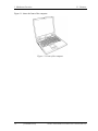
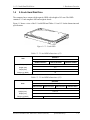
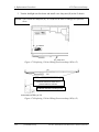
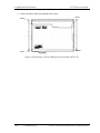
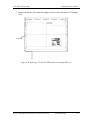
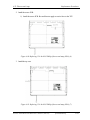
Figure 1-1 shows the front of the computer.
Figure 1-1 Front of the computer
1-4
[CONFIDENTIAL]
Satellite A50S/TECRA A3X Maintenance Manual (960-534)
1.1 Features
1 Hardware Overview
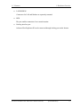
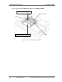
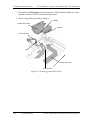
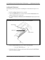
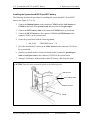
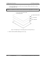
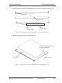
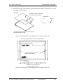
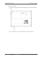
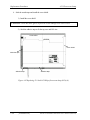
Figure 1-2 shows the system units configuration.
Figure 1-2 System units configuration
Satellite A50S/TECRA A3X Maintenance Manual (960-534)
[CONFIDENTIAL]
1-5
1 Hardware Overview
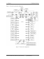
1.2
1.2 System Block Diagram
System Block Diagram
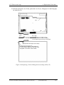
Figure 1-3 shows the system block diagram.
Figure 1-3 System Block Diagram
1-6
[CONFIDENTIAL]
Satellite A50S/TECRA A3X Maintenance Manual (960-534)
1.2 System Block Diagram
1 Hardware Overview
The PC contains the following components.
? CPU
Intel® Mobile Pentium® -M model
Pentium-M
1.60GHz (Processor Number ; 730)
1.73GHz (Processor Number ; 740)
1.86GHz (Processor Number ; 750)
2.00GHz (Processor Number ; 760)
2.13GHz (Processor Number ; 770)
2.26GHz (Processor Number ; 780)
L1 cache : 64KB (32KB + 32KB)
L2 cache : 2MB
FSB : 533MHz
Core voltage : 1.280~1.356V
Intel® Mobile Celeron® -M model
Celeron-M
1.40GHz (Processor Number ; 360)
1.50GHz (Processor Number ; 370)
1.60GHz (Processor Number ; 380)
1.70GHz (Processor Number ; 390)
L1 cache : 64KB (32KB + 32KB)
L2 cache : 1MB
FSB : 400MHz
Core voltage : 1.004~1.292V
? Memory
Two memory slots capable of accepting 256MB, 512MB or 1024MB memory
modules for a maximum of 2GB.
?
?
?
200-pin DDR-SDRAM (PC4300)
Pipeline configuration
2.5V operation
? Firmware Hub
?
?
?
8Mbit (Flash memory)
Vcc : 3.3V±0.3V
Vpp : 3.3V/12V
Satellite A50S/TECRA A3X Maintenance Manual (960-534)
[CONFIDENTIAL]
1-7
1 Hardware Overview
1.2 System Block Diagram
? Chipset
This gate array has the following elements and functions.
? North Bridge (Intel 915GM <Express Chipset>)
- Support Pentium-M(915GM)/Celeron-M(915GM/910GML) Processor
System Bus
- System Memory Interface
- Memory Controller : DDR333/DDR2-400/DDR2-533, 2GB(max)
- Graphics I/F : x16 PCI Express Based Graphics I/F
- DMI (Direct Media Interface)
- Integrated Display interface
- 1,257-ball 40.0mmx37.5mmx2.6mm FC-BGA Package
? South Bridge (Intel 82801DBM (ICH6-M))
- DMI (Direct Media Interface)
- PCI Express I/F (4 ports)
- PCI Bus I/F Rev 2.3 (PCI REQ/GNT Pairs)
- Integrated Serial ATA Host Controller (2 ports, 150MB/S)
- Integrated IDE Controller (Ultra ATA 100/66/33)
- AC’97 2.3 codes
- USB 1.1/2.0 Controller 8 ports (EHCI: Enhanced Host Controller
Interface)
- Built- in LAN Controller (Wfm 2.0& IEEE802.3 compliance)
- Power Management (ACPI 2.0 compliance)
- SMBus2.0 controller
- FWH interface (BIOS)
- LPC interface (EC/KBC, Super I/O)
- IRQ controller
- Serial Interrupt Function
- Suspend/Resume control
- Built- in RTC
- GPIO
- 609-ball 31mmx31mm micro BGA Package
? PC card controller (Texas Instruments PCI7411)
- PCI Interface (PCI Rev. 2.3)
- PC Card Controller
- IEEE1394 Controller
- Flash Media Controller
- SD Host Controller
1-8
[CONFIDENTIAL]
Satellite A50S/TECRA A3X Maintenance Manual (960-534)
1.2 System Block Diagram
1 Hardware Overview
? VGA controller
Imbedded in North Bridge
? Other main system chips
?
?
?
?
?
?
EC/KBC (M306KAFCLRP x 1)
PSC (Toshiba- made TMP86PM49UG x 1)
Thermal sensor (AnalogDevice- made ADM1032 x 1)
Audio AMP (Mitsumi- made MM1517X x1)
AC97-CODEC (SigmaTel- made STAC9750TG x1)
Clock generator (ICS954204 x1)
? Mini PCI (Intel/Askey made 802.11b/g or 802.11a/b/g)
2.4 GHz DSSS wireless LAN card is equipped in the mini PCI card slot. Conformity
with IEEE 802.11b (WiFi). Supports 128bit WEP.
? LAN (Intel- made Kinnereth (ED82562 x 1)
Controls LAN.
Supports 100Base-TX and 10Base-T.
? MODEM (Askey-made 1456VQL4A (INT) x 1)
Supported by MDC.
Uses secondary AC97 line.
Data and FAX transmission is available.
Supports ITU-TV.90 and V.92.
The transfer speed of data receiving is 56kbps, of data sending is 33.6kbps and of
FAX is 14.4Kbps. Actual speed depends on the quality of the line used.
Connected to telephone line through RJ11 modem jack.
Satellite A50S/TECRA A3X Maintenance Manual (960-534)
[CONFIDENTIAL]
1-9
1 Hardware Overview
1.3
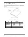
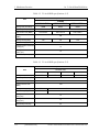
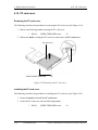
1.3 3.5-inch USB Floppy Disk Drive
3.5-inch USB Floppy Disk Drive
This compact, lightweight and high-reliability FDD can be used with 720KB and 1.44MB
floppy disks.
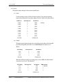
Figure 1-4 shows the 3.5- inch FDD. Table 1-1 lists the specifications.
Figure 1-4 3.5-inch USB FDD
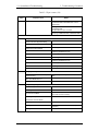
Table 1-1 3.5-inch USB FDD specifications
Item
Disk used
1-10
Specifications
2DD
2HD
Unformatted capacity
1.0MB
2.0MB
Formatted capacity
720KB
1.44MB
Data transfer speed
( Kb/s)
250
500
Rotation speed( rpm)
300
300
[CONFIDENTIAL]
Satellite A50S/TECRA A3X Maintenance Manual (960-534)
1.4 2.5-inch Hard Disk Drive
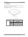
1.4
1 Hardware Overview
2.5-inch Hard Disk Drive
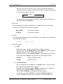
The computer has a compact, high-capacity HDD with a height of 9.5 mm. The HDD
contains a 2.5- inch magnetic disk and magnetic heads.
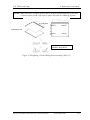
Figure 1-5 shows a view of the 2.5- inch HDD and Tables 1-2 and 1-3 list the dimensions and
specifications.
Figure 1-5 2.5-inch HDD
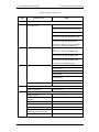
Table 1-2 2.5-inch HDD dimensions (1/2)
Standard
Item
TOSHIBA
HDD2193VZK01
HDD2194VZK01
Width (mm)
69.85
Height (mm)
9.5
Depth (mm)
100.0
Weight (g) (MAX)
95
HDD2191VZK01
Table 1-2 2.5-inch HDD dimensions (2/2)
Standard
Item
HITACHI-GST
G8BC0001N410
G8BC0001N610
G8BC0001N810
Width (mm)
69.85±0.25
Height (mm)
9.5±0.2
Depth (mm)
100.2±0.25
Weight (g) (MAX)
95
Satellite A50S/TECRA A3X Maintenance Manual (960-534)
G8BC0001NA10
102
[CONFIDENTIAL]
1-11
1 Hardware Overview
1.4 2.5-inch Hard Disk Drive
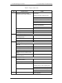
Table 1-3 2.5-inch HDD specifications (1/2)
Specifications
Item
TOSHIBA
HDD2193VZK01
HDD2194VZK01
HDD2191VZK01
40GB
60GB
80GB
Storage size (formatted)
5,400
Rotation speed (RPM)
154.3-298.0
Data transfer rate (MB/s)
258.0-394.0
Interface transfer rate
(MB/s)
233.0-446.0
100
728
Storage density (Kbpi)
735
728
88.8
Track density (Ktpi)
Average random seek time
(read) (ms)
12
Average random seek time
(write) (ms)
12
Motor startup time (ms)
4
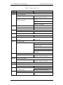
Table 1-3 2.5-inch HDD specifications (2/2)
Specifications
Item
HITACHI-GST
G8BC0001N410
G8BC0001N610
G8BC0001N810
G8BC0001NA10
40GB
60GB
80GB
100GB
Storage size (formatted)
5,400
Rotation speed (RPM)
Data transfer rate (MB/s)
493
Interface transfer rate
(MB/s)
100
Storage density (Kbpi)
717
764
Track density (Ktpi)
96.6
113.2
Average random seek time
(read) (ms)
14
Average random seek time
(write) (ms)
12
Motor startup time (ms)
3.5
1-12
[CONFIDENTIAL]
Satellite A50S/TECRA A3X Maintenance Manual (960-534)
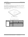
1.5 CD-ROM Drive
1.5
1 Hardware Overview
CD-ROM Drive
The CD-ROM drive accommodates either 12 cm (4.72- inch) or 8 cm (3.15- inch) CD. It is a
high-performance drive that reads at maximum 24-speed.
The CD-ROM drive is shown in Figure 1-6. The specifications of the CD-ROM drive are
described in Table 1-4 and 1-5.
Figure 1-6 CD-ROM drive
Table 1-4 CD-ROM drive dimensions
Item
Maker
Dimensions
Standard
TEAC
(G8CC0002R220)
Width (mm)
128
Height (mm)
12.7
Depth (mm)
129.4
Weight (g)
165 (max)
Satellite A50S/TECRA A3X Maintenance Manual (960-534)
[CONFIDENTIAL]
1-13
1 Hardware Overview
1.5 CD-ROM Drive
Table 1-5 CD-ROM drive specifications
Specifications
Items
Transfer
Speed
Access Time
(ms)
TEAC
(G8CC0002R220)
Data transfer rate
(MB/s)
Burst data
transfer rate
(MB/s)
CD-ROM
1-14
PIO mode 16.7 MB/s (PIO MODE4)
DMA mode 16.7 MB/s (Multiword MODE2)
Ultra DMA mode 33.3 MB/s (Ultra DMA MODE2)
110 (Random)
240 (Full stroke)
Buffer memory
Supported
formats
33.3Mbytes/sec (max)
1,545 – 3,600KB/sec
CD
[CONFIDENTIAL]
256KB
CD-DA, CD-ROM Mode1, Mode2
CD-ROM XA Mode2 (Form1, Form2),
Photo CD (single/multi-session), Enhanced CD
Satellite A50S/TECRA A3X Maintenance Manual (960-534)
1.6 DVD-ROM Drive
1.6
1 Hardware Overview
DVD-ROM Drive
The DVD-ROM drive accommodates either 12 cm (4.72- inch) or 8 cm (3.15- inch) CD, CDR/RW and DVD. It is a high-performance drive that reads DVD at maximum 8-speed, and
reads CD at maximum 24-speed (3,600 KB per second).
The DVD-ROM drive is shown in Figure 1-7. The specifications of the DVD-ROM drive are
described in Table 1-6 and 1-7.
Figure 1-7 DVD-ROM drive
Table 1-6 DVD-ROM drive dimensions
Standard
Item
Maker
Dimensions
TSST
(G8CC0002W220)
TEAC
(G8CC0002E220)
Width (mm)
128
Height (mm)
12.7
Depth (mm)
129.0
Weight (g)
179 ±15
Satellite A50S/TECRA A3X Maintenance Manual (960-534)
[CONFIDENTIAL]
1-15
1 Hardware Overview
1.6 DVD-ROM Drive
Table 1-7 DVD-ROM drive specifications (1/2)
Specifications
Items
Transfer Speed
Access Time
(ms)
TSST
(G8CC0002W220)
Data transfer
rate
(MB/s)
Burst data
transfer rate
(MB/s)
PIO mode 16.7 MB/s (PIO Mode 4)
DMA mode 16.7 MB/s (Multi-word DMA Mode 2)
Ultra DMA mode 33.3 MB/s (Ultra DMA Mode 2)
CD-ROM
110 (Random)
DVD-ROM
110 (Random)
DVD-RAM
140 (Random)
Buffer Memory
256KB
CD
CD-DA, CD+(E)G, CD-MIDI,CD-text, CD-ROM,
CD-ROM XA, CD-I, CD-I Bridge, Multi-session CD, CD-R,
CD-RW
DVD
DVD-ROM (DVD-5, DVD-9, DVD-10, DVD-18), DVD-R
(Ver1.0, 2.1), DVD-RW (Ver1.0, 1.1)
DVD+R, DVD+R DL, DVD+RW,
DVD-RAM (Ver2.1)
Supported
formats
1-16
DVD(Single Layer); 4,460-10,816 (CAV)
DVD(Dual Layer); 3,380-8,112 (CAV)
DVD-R/-RW; 2,298-5,408 (CAV)
DVD+R/+RW; 2,298-5,408 (CAV)
DVD+R Double Layer; 2,298-5,408 (CAV)
DVD-RAM; 2,704 (ZoneCLV)
CD(Mode1); 1,546-3,600 (CAV)
CD(Mode2); 1,761-4,104 (CAV)
[CONFIDENTIAL]
Satellite A50S/TECRA A3X Maintenance Manual (960-534)
1.6 DVD-ROM Drive
1 Hardware Overview
Table 1-7 DVD-ROM drive specifications (2/2)
Specifications
Items
Transfer Speed
Access Time
(ms)
TEAC
(G8CC0002E220)
Data transfer
rate
(MB/s)
DVD-ROM; 8x (CAV)
DVD-Video; 4x (CAV)
CD-ROM (Mode1); 24x (CAV)
CD-ROM (Mode2); 20x (CAV)
CD-DA; 20x (CAV)
CD-RW; 24x (CAV)
DVD-R/-RW; 8x (CAV)
DVD+R/+RW; 8x (CAV)
DVD-RAM (4.7GB); 5x (CAV)
DVD-RAM (2.6GB); 2.5x (CAV)
Burst data
transfer rate
(MB/s)
PIO mode 16.7 MB/s (PIO Mode 4)
DMA mode 16.7 MB/s (Multi-word DMA Mode 2)
Ultra DMA mode 33.3 MB/s (Ultra DMA Mode 2)
CD-ROM
120 (Random)
DVD-ROM
130 (Random)
Buffer Memory
Supported
formats
256KB
CD
CD-DA, CD-ROM Mode1, CD-ROM XA Mode2,
Multi-session CD, CD-I, Video CD, Enhanced CD,
CD-TEXT, Photo CD, Addressing Method2
DVD
DVD-ROM, DVD-R, DVD Video, DVD-RW
DVD+R, DVD+RW, DVD-RAM (2.6GB/4.7GB)
Satellite A50S/TECRA A3X Maintenance Manual (960-534)
[CONFIDENTIAL]
1-17
1 Hardware Overview
1.7
1.7 DVD-ROM & CD-R/RW Drive
DVD-ROM & CD-R/RW Drive
The DVD-ROM & CD-R/RW drive accommodates either 12 cm (4.72-inch) or 8 cm (3.15inch) CD, CD-R/RW and DVD. It is a high-performance drive that reads DVD at maximum
8-speed, and reads CD at maximum 24-speed.
The DVD-ROM & CD-R/RW drive is shown in Figure 1-8. The specifications of the DVDROM & CD-R/RW drive are described in Table 1-8 and 1-9.
Figure 1-8 DVD-ROM & CD-R/RW drive
Table 1-8 DVD-ROM & CD-R/RW drive dimensions
Items
Maker
Dimensions
Panasonic
(G8CC0002J220)
TSST
(G8CC0002V220)
Width (mm)
128
Height (mm)
12.7
Depth (mm)
129.0
Weight (g)
1-18
Standard
[CONFIDENTIAL]
180 ±10
179 ±15
Satellite A50S/TECRA A3X Maintenance Manual (960-534)
1.7 DVD-ROM & CD-R/RW Drive
1 Hardware Overview
Table 1-9 DVD-ROM & CD-R/RW drive specifications (1/2)
Specifications
Items
Transfer Speed
Panasonic
(G8CC0002J220)
Read(KB/s)
CD-ROM; 24x (CAV)
DVD-ROM MAX 8x CAV
Write
CD-R 24x (CAV)
CD-RW 4x (CLV)
High Speed CD-RW 10x (CLV)
Ultra Speed CD-RW 24x (CAV)
Burst data
transfer rate
(MB/s)
Access Time
(ms)
PIO mode 16.6 MB/s (PIO Mode 4)
DMA mode 16.6 MB/s (Multi-word DMA Mode 2)
Ultra DMA mode 33.3 MB/s (Ultra DMA Mode 2)
CD-ROM
150 (Random)
DVD-ROM
180 (Random)
Buffer Memory
Supported
formats
2MB
CD
CD-DA, CD-ROM, CD-ROM XA, Photo CD,
CD-Extra(CD+), CD-Text
DVD
DVD-R, DVD-RW,
DVD Video, DVD+R, DVD+RW,
DVD-RAM
Satellite A50S/TECRA A3X Maintenance Manual (960-534)
[CONFIDENTIAL]
1-19
1 Hardware Overview
1.7 DVD-ROM & CD-R/RW Drive
Table 1-9 DVD-ROM & CD-R/RW drive specifications (2/2)
Specifications
Items
Transfer Speed
TSST
(G8CC0002V220)
Read(KB/s)
CD-ROM; 24x (CAV)
CD-RW; 24x (CAV)
DVD-ROM MAX 8x CAV
Write
CD-R 24x (P-CAV)
CD-RW 4x (CLV)
High Speed CD-RW 10x (CLV)
Ultra Speed CD-RW 24x (P-CAV)
Burst data
transfer rate
(MB/s)
Access Time
(ms)
CD-ROM
130 (Random)
DVD-ROM
150 (Random)
Buffer Memory
Supported
formats
1-20
PIO mode 16.6 MB/s (PIO Mode 4)
DMA mode 16.6 MB/s (Multi-word DMA Mode 2)
Ultra DMA mode 33.3 MB/s (Ultra DMA Mode 2)
2MB
CD
CD-ROM, CD-R, CD-RW, CD-Audio Disc,
CD-DA, Video-CD
DVD
DVD-R, DVD-RW,
DVD Video, DVD+R, DVD+RW,
DVD-RAM
[CONFIDENTIAL]
Satellite A50S/TECRA A3X Maintenance Manual (960-534)
1.8 DVD Super Multi drive
1.8
1 Hardware Overview
DVD Super Multi drive
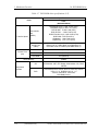
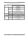
The DVD Multi drive accommodates either 12 cm (4.72-inch) or 8 cm (3.15- inch) CD, CDR/RW and DVD. It is a high-performance drive that reads CD at maximum 24-speed (3,600
KB per second) and writes DVD-RW at 2-speed, DVD-RAM at 2-speed, DVD-R at4-speed,
DVD+R at 2.4-speed and DVD+RW at 2.4-speed.
The DVD Super Multi drive is shown in Figure 1-9. The specifications of the DVD Super
Multi drive are described in Table 1-10 and 1-11.
Figure 1-9 DVD Super Multi drive
Table 1-10 DVD Super Multi drive dimensions
Items
Maker
Dimensions
Standards
Panasonic
(G8CC0002T220)
TEAC
(G8CC0002S220)
Width (mm)
128
Height (mm)
12.7
Depth (mm)
129.0
129.4
Weight (g)
190 ±10
190 (max)
Satellite A50S/TECRA A3X Maintenance Manual (960-534)
[CONFIDENTIAL]
1-21
1 Hardware Overview
1.8 DVD Super Multi drive
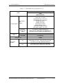
Table 1-11 DVD Super Multi drive specifications (1/2)
Specifications
Items
Transfer Speed
Access Time
(ms)
Panasonic
(G8CC0002T220)
Read(KB/s)
DVD-ROM MAX 8x CAV
CD-ROM MAX 24x CAV
Write
CD-R 24x (ZoneCLV)
CD-RW 4x (CLV)
High Speed CD-RW 10x (CLV)
Ultra Speed CD-RW 10x (CLV)
DVD-R 8x (ZoneCLV)
DVD-R Double Layer 2x (CLV)
DVD-RW 4x (ZoneCLV)
DVD+R 8x (ZoneCLV)
DVD+R Double Layer 2.4x (CLV)
DVD+RW 4x (ZoneCLV)
DVD-RAM 5x (ZoneCLV)
Burst data
transfer rate
(MB/s)
PIO mode 16.6 MB/s (PIO Mode 4)
DMA mode 16.6 MB/s (Multi-word DMA Mode 2)
Ultra DMA mode 33.3 MB/s (Ultra DMA Mode 2)
CD-ROM
150 (Random)
DVD-ROM
180 (Random)
Buffer memory
Supported
formats
1-22
2MB
CD
CD-DA, CD-ROM, CD-ROM XA,
Photo CD, CD-Extra(CD+),CD-text
DVD
DVD-R, DVD-RW (Ver1.1)
DVD Video, DVD+R, DVD+RW,
DVD-RAM (2.6GB/4.7GB)
[CONFIDENTIAL]
Satellite A50S/TECRA A3X Maintenance Manual (960-534)
1.8 DVD Super Multi drive
1 Hardware Overview
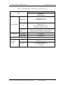
Table 1-11 DVD Super Multi drive specifications (2/2)
Specifications
Items
Transfer Speed
Access Time
(ms)
TEAC
(G8CC0002S220)
Read(KB/s)
DVD-ROM 8x (CAV)
CD-ROM 24x (CAV)
Write
CD-R 24x (ZoneCLV)
CD-RW 16x (CLV)
DVD-R 8x (ZoneCLV)
DVD-RW 4x (ZoneCLV)
DVD+R 8x (ZoneCLV)
DVD+R Double Layer 2.4x (CLV)
DVD+RW 4x (ZoneCLV)
DVD-RAM 3x (ZoneCLV)
Burst data
transfer rate
(MB/s)
PIO mode 16.7 MB/s (PIO Mode 4)
DMA mode 16.7 MB/s (Multi-word DMA Mode 2)
Ultra DMA mode 33.3 MB/s (Ultra DMA Mode 2)
CD-ROM
130 (Random)
DVD-ROM
130 (Random)
Buffer memory
Supported
formats
2MB
CD
CD-DA, CD-ROM, CD-ROM XA, CD-I, Video CD,
Photo CD, CD-Extra(CD+),CD-text
DVD
DVD-R, DVD-RW (Ver1.1), DVD Video, DVD+R,
DVD+R (Double layer), DVD+RW,
DVD-RAM (2.6GB/4.7GB)
Satellite A50S/TECRA A3X Maintenance Manual (960-534)
[CONFIDENTIAL]
1-23
1 Hardware Overview
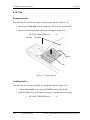
1.9
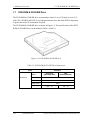
1.9 Keyboard
Keyboard
An 85(US)-/86(UK)- key keyboard is mounted on the system unit. The keyboard is
connected to membrane connector on the system board and controlled by the keyboard
controller.
Figure 1-10 shows a view of the keyboard.
See Append ix E for details of the keyboard layout.
Figure 1-10 Keyboard
1-24
[CONFIDENTIAL]
Satellite A50S/TECRA A3X Maintenance Manual (960-534)
1.10 TFT Color Display
1 Hardware Overview
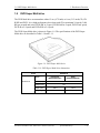
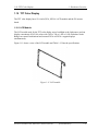
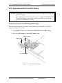
1.10 TFT Color Display
The TFT color display has a 15.0- inch (XGA, SXGA+) LCD module and the FL inverter
board.
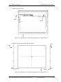
1.10.1 LCD Module
The LCD module used for the TFT color display uses a backlight as the light source and can
display a maximum of 262,144 colors with 1,024 x 768 or 1,400 x 1,050 resolution. North
Bridge can control both internal and external XGA or SXGA+ support displays
simultaneously.
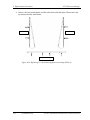
Figure 1-11 shows a view of the LCD module and Table 1-12 lists the specifications.
Figure 1-11 LCD module
Satellite A50S/TECRA A3X Maintenance Manual (960-534)
[CONFIDENTIAL]
1-25
1 Hardware Overview
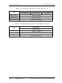
1.10 TFT Color Display
Table 1-12 LCD module specifications (15.0-inch XGA TFT) (1/2)
Specifications
Item
G33C0002W110
G33C0002Y110
Number of Dots
1,024(W) × 768(H)
Dot spacing (mm)
0.297(H)× 0.297(V)
Display range (mm)
G33C00030110
304.128(H)× 228.096(V)
Table 1-12 LCD module specifications (15.0-inch SXGA+ TFT) (2/2)
Specifications
Item
G33C0001X210
Number of Dots
1,400(W)× 1,050(H)
Dot spacing (mm)
0.2175(H)× 0.2175(V)
Display range (mm)
304.5(H)× 228.375(V)
1-26
[CONFIDENTIAL]
Satellite A50S/TECRA A3X Maintenance Manual (960-534)
1.10 TFT Color Display
1 Hardware Overview
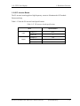
1.10.2 FL Inverter Board
The FL inverter board supplies a high frequency current to illuminate the LCD module
fluorescent lamp.
Table 1-13 lists the FL inverter board specifications.
Table 1-13 FL inverter board specifications
Item
Input
Output
Specifications
Voltage (V)
DC5
Power (W)
7
Voltage (V)
750
Current (mA)
6.00
Power (W)
Satellite A50S/TECRA A3X Maintenance Manual (960-534)
5W/7VA
[CONFIDENTIAL]
1-27
1 Hardware Overview
1.11 Power Supply
1.11 Power Supply
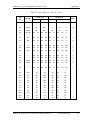
The power supply supplies 26 different voltages to the system board.
The power supply microcontroller has the following functions.
1.
2.
3.
4.
5.
6.
7.
8.
Judges if the DC power supply (AC adapter) is connected to the computer.
Detects DC output and circuit malfunctions.
Controls the battery icon, and DC IN icon.
Turns the battery charging system on and off and detects a fully charged battery.
Turns the power supply on and off.
Provides more accurate detection of a low battery.
Calculates the remaining battery capacity.
Controls the transmission of the status signal of the main battery.
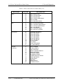
Table 1-14 lists the power supply output specifications.
1-28
[CONFIDENTIAL]
Satellite A50S/TECRA A3X Maintenance Manual (960-534)
1.11 Power Supply
1 Hardware Overview
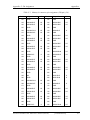
Table 1-14 Power supply output rating
Power Supply (Yes / No)
Name
Voltage
[V]
S3
S4/S5
G3
Use
No
No
No
CPU
No
No
No
No
No
No
PTV
PGV
1.308 –
0.748
1.05
1.056
1R5-P1V
1.5
No
No
No
1R8-B1V
VG1R8-P1V
2R5-P2V
MR0R9-B0V
0R9-P0V
1.8
1.8
2.5
0.9
0.9
Yes
No
No
Yes
No
No
No
No
No
No
No
No
No
No
No
P3V
3.3
No
No
No
E3V
3.3
Yes
Yes / No
No
SD-E3V
LAN-E3V
LAN2R5-E2V
BT-P3V
USB0PS-E5V
USB1PS-E5V
3.3
3.3
2.5
3.3
5
5
No
Yes
Yes
No
Yes
Yes
No
Yes / No
Yes / No
No
Yes / No
Yes / No
No
No
No
No
No
No
S3V
3.3
Yes
Yes
No
P5V
5
No
No
No
1R5-E1V
SND-P5V
A4R7-P4V
1.5
5
4.7
Yes
No
No
Yes / No
No
No
No
No
No
E5V
5
Yes
Yes / No
No
M5V
MCV
5
5
2.0 3.5
Yes
Yes
Yes
Yes
No
No
CPU, MCH, ICH6-M
GPU
CPU, MCH, ICH6-M,
ExpressCard
MCH, DDR2-SDRAM
GPU
MCH, ICH6-M
MCH, DDR2-SDRAM
DDR2-SDRAM
Clock Generator, GPU,
Thermal Sensor, TPM,
SDRAM(SPD), Mini-PCI,
Super I/O, ICH6-M,
LCD, Express Card,
FWH, FIR, STAC9200,
HDD(SATA),
Finger Print Sensor
ICH6-M, TI CARD Cont., PC
Card Power, Mini-PCI, Express
Card, MDC, RS-232C
SD Card
LAN Power
LAN Power
Bluetooth
USB
USB
EC/KBC, PSC,
3AXIS Accerelometer
CRT, ICH6-M, FL inverter, LEDs,
ODD, KB, PAD,Bluetooth Power,
HDD(SATA), Parallel
ICH6-M
AN12941
STAC9200, AN12941
ICH6-M, PC Card Power, USB
Power
Docker, MAX6501, LED
PSC
Yes
Yes
Yes
ICH6-M(RTC)
PPV
R3V
Satellite A50S/TECRA A3X Maintenance Manual (960-534)
[CONFIDENTIAL]
1-29
1 Hardware Overview
1.12 Batteries
1.12 Batteries
The PC has the following two batteries.
? Main battery
? Real time clock (RTC) battery
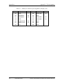
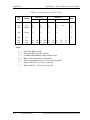
Table 1-15 lists the specifications for these two batteries.
Table 1-15 Battery specifications
Battery Name
Capacity
Material
Output
Voltage
G71C0003V910
G71C0003VA10
G71C0003VD10
4,400mAh
G71C0003VE10
Main battery
lithium ion
(6-cell)
G71C0005H110
10.8V
G71C0005H210
G71C0004G510
G71C0004G610
G71C0003W210
G71C0003W110
Real time clock
(RTC) battery
GDM710000041
4,700mAh
8,800mAh
lithium ion
(12-cell)
17mAh
Nickel metal
hydride
3.0V
1.12.1 Main Battery
The main battery is the primary power supply for the computer when the AC adapter is not
connected. In resume (instant recovery) mode, the main battery maintains the current status
of the computer.
1-30
[CONFIDENTIAL]
Satellite A50S/TECRA A3X Maintenance Manual (960-534)
1.12 Batteries
1 Hardware Overview
1.12.2 Battery Charging Control
Battery charging is controlled by a power supply microprocessor. The power supply
microprocessor controls power supply and detects a full charge when the AC adaptor and
battery are connected to the computer.
? Battery Charge
When the AC adapter is connected, normal charging is used while the system is
turned on, and quick charge is used while the system is turned off or in suspend mode.
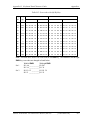
Table 1-16 shows the time required for charges of main battery.
Table 1-16 Time required for charges of main battery
Condition
Normal charge
Quick charge
Charging Time
4,400mAh
About 4.5 to 12.0 hours or longer
8,800mAh
About 7.0 to 21.0 hours or longer
4,400mAh
About 3.0 hours
8,800mAh
About 4.5 hours
Charge is stopped in the following cases.
1. The main battery is fully charged
2. The main battery is removed
3. Main battery or AC adapter vo ltage is abnormal
4. Charging current is abnormal
? Battery preservation time
When turning off the power in being charged fully, the preservation time is as
follows:
Table 1-17 Battery preservation time
Condition
Preservation Time
Power OFF
or
Hibernation
4,400mAh
About 85 days
8,800mAh
About 160 days
Stanby
4,400mAh
About 5 days
8,800mAh
About 8 days
Satellite A50S/TECRA A3X Maintenance Manual (960-534)
[CONFIDENTIAL]
1-31
1 Hardware Overview
1.12 Batteries
1.12.3 RTC Battery
The RTC battery provides the power supply to maintain the date, time, and other system
information in memory.
Table 1-18 lists the Time required for charges of RTC battery.
Table 1-18 Time required for charges of RTC battery
Condition
Power ON (Lights Power LED)
Power OFF (Doesn’t light Power LED)
1-32
[CONFIDENTIAL]
Time
8 hours or longer
Does n’t charge
Satellite A50S/TECRA A3X Maintenance Manual (960-534)
1.13 AC Adapter
1 Hardware Overview
1.13 AC Adapter
The AC adapter is used to charge the battery.
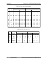
Table 1-19 lists the AC adapter specifications.
Table 1-19 AC adapter specifications (1/2)
Item
Specifications
G71C0002SB10
G71C0004A410
Input voltage
100V/240V
Input frequency
50Hz/60Hz
No load input power
0.5W or less
Output voltage
15.0V
Output current
4.0A
Table 1-19 AC adapter specifications (2/2)
Item
Specifications
G71C00049310/
G71C00049410
G71C00043310
Input voltage
100V/240V
Input frequency
No load input power
47Hz - 63Hz
0.7W or less
1.0W or less
Output voltage
15.0V
Output current
5.0A
Satellite A50S/TECRA A3X Maintenance Manual (960-534)
[CONFIDENTIAL]
1-33
1 Hardware Overview
1-34
[CONFIDENTIAL]
1.13 AC Adapter
Satellite A50S/TECRA A3X Maintenance Manual (960-534)
Chapter 2
Troubleshooting Procedures
[CONFIDENTIAL]
2 Troubleshooting Procedures
2
2-ii
[CONFIDENTIAL]
Satellite A50S/TECRA A3X Maintenance Manual (960-534)
2 Troubleshooting Procedures
Chapter 2
Contents
2.1
Troubleshooting ......................................................................................................... 2-1
2.2
Troubleshooting Flowchart........................................................................................ 2-2
2.3
Power Supply Troubleshooting.................................................................................. 2-6
2.4
2.5
2.6
2.7
Procedure 1
Power Status Check ............................................................... 2-6
Procedure 2
Error Code Check................................................................... 2-8
Procedure 3
Connection Check ................................................................ 2-13
Procedure 4
Charging Check.................................................................... 2-13
Procedure 5
Replacement Check.............................................................. 2-14
System Board Troubleshooting................................................................................ 2-15
Procedure 1
Message Check .................................................................... 2-16
Procedure 2
Debug Port Check ................................................................ 2-18
Procedure 3
Diagnostic Test Program Execution Check ......................... 2-28
Procedure 4
Replacement Check.............................................................. 2-28
3.5” FDD Troubleshooting ...................................................................................... 2-29
Procedure 1
FDD Head Cleaning Check.................................................. 2-29
Procedure 2
Diagnostic Test Program Execution Check ......................... 2-30
Procedure 3
Connector Check and Replacement Check .......................... 2-31
2.5” HDD Troubleshooting...................................................................................... 2-32
Procedure 1
Partition Check..................................................................... 2-32
Procedure 2
Message Check .................................................................... 2-33
Procedure 3
Format Check ....................................................................... 2-34
Procedure 4
Diagnostic Test Program Execution Check ......................... 2-35
Procedure 5
Connector Check and Replacement Check .......................... 2-36
Keyboard Troubleshooting ...................................................................................... 2-37
Procedure 1
Diagnostic Test Program Execution Check ......................... 2-37
Procedure 2
Connector Check and Replacement Check .......................... 2-37
Satellite A50S/TECRA A3X Maintenance Manual (960-534)
[CONFIDENTIAL]
2-iii
2 Troubleshooting Procedures
2.8
2.9
2.10
2.11
2.12
2.13
2.14
2-iv
Display Troubleshooting.......................................................................................... 2-38
Procedure 1
External Monitor Check....................................................... 2-38
Procedure 2
Diagnostic Test Program Execution Check ......................... 2-38
Procedure 3
Connector and Cable Check................................................. 2-39
Procedure 4
Replacement Check.............................................................. 2-40
Touch Pad Troubleshooting ..................................................................................... 2-41
Procedure 1
Diagnostic Test Program Execution Check ......................... 2-41
Procedure 2
Connector Check and Replacement Check .......................... 2-41
Optical Drive Troubleshooting ................................................................................ 2-42
Procedure 1
Diagnostic Test Program Execution Check ......................... 2-42
Procedure 2
Connector Check and Replacement Check .......................... 2-42
Modem Troubleshooting.......................................................................................... 2-43
Procedure 1
Diagnostic Test Program Execution Check ......................... 2-43
Procedure 2
Connector Check and Replacement Check .......................... 2-43
LAN Troubleshooting .............................................................................................. 2-44
Procedure 1
Diagnostic Test Program Execution Check ......................... 2-44
Procedure 2
Connector Check and Replacement Check .......................... 2-44
Sound Troubleshooting ............................................................................................ 2-45
Procedure 1
Diagnostic Test Program Execution Check ......................... 2-45
Procedure 2
Connector Check.................................................................. 2-45
Procedure 3
Replacement Check.............................................................. 2-46
Wireless LAN Troubleshooting ............................................................................... 2-47
Procedure 1
Transmitting- Receiving Check ............................................ 2-47
Procedure 2
Antennas' Connection Check ............................................... 2-47
Procedure 3
Replacement Check.............................................................. 2-48
[CONFIDENTIAL]
Satellite A50S/TECRA A3X Maintenance Manual (960-534)
2 Troubleshooting Procedures
Figures
Figure 2-1
Troubleshooting flowchart ............................................................................. 2-3
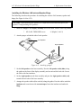
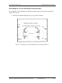
Figure 2-2
A set of tool for debug port test ................................................................... 2-18
Tables
Table 2-1
Battery icon.................................................................................................... 2-6
Table 2-2
DC IN icon..................................................................................................... 2-6
Table 2-3
D port status ................................................................................................ 2-19
Table 2-4
FDD error code and status ........................................................................... 2-30
Table 2-5
2.5” Hard disk drive error code and status................................................... 2-35
Satellite A50S/TECRA A3X Maintenance Manual (960-534)
[CONFIDENTIAL]
2-v
2.1 Troubleshooting
2 Troubleshooting Procedures
2
2.1
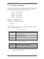
Troubleshooting
Chapter 2 describes how to determine which Field Replaceable Unit (FRU) in the
computer is causing the computer to malfunction. (The “FRU” means the replaceable unit
in the field.) The FRUs covered are:
1.
2.
3.
4.
5.
6.
Power supply
System Board
3.5” USB FDD
2.5” HDD
Keyboard
Display
7.
8.
9.
10.
11.
12.
Touch pad
Optical Drive
Modem
LAN
Sound
Wireless LAN
13. Wireless LAN
The Test Program operations are described in Chapter 3. Detailed replacement procedures
are given in Chapter 4.
The following tools are necessary for implementing the Diagnostics procedures (also tools
for Chapter 3 annd Chapter 4 are necesarry if it is required.):
1. Diagnostics Disk (Test program for maintenance)
2. Phillips screwdrivers
NOTE: Be sure to use the PH point size “0” screwdriver complying with the ISO/DIS
8764 -1:1996.
3. Toshiba MS-DOS system FD
4. Tester
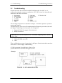
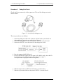
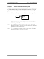
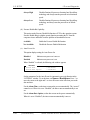
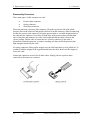
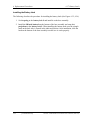
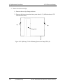
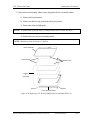
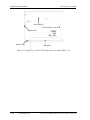
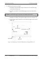
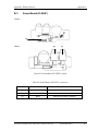
There are following two types of connections in the figure of board and module connection
in and after 2.3 Power Supply Troubleshooting.
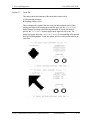
(1) Cable connection is described in the figure as line.
(2) Pin connection is described in the figure as arrow.
<Example>
Satellite A50S /TECRA A3X Maintenance Manual (960-534)
[CONFIDENTIAL]
2-1
2 Troubleshooting Procedures
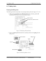
2.2
2.2 Troubleshooting Flowchart
Troubleshooting Flowchart
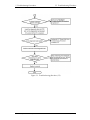
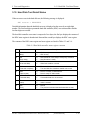
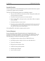
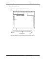
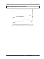
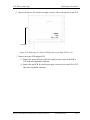
Use the flowchart in Figure 2-1 as a guide for determining which troubleshooting
procedure is executed. Before going through the flowchart steps, check the following:
? Make sure that Toshiba Windows® OS is installed on the hard disk. Non-Toshiba
operating systems can cause the computer malfunction.
? Make sure all optional equipment is removed from the computer.
2-2
[CONFIDENTIAL]
Satellite A50S/TECRA A3X Maintenance Manual (960-534)
2.2 Troubleshooting Flowchart
2 Troubleshooting Procedures
Figure 2-1 Troubleshooting flowchart (1/2)
Satellite A50S /TECRA A3X Maintenance Manual (960-534)
[CONFIDENTIAL]
2-3
2 Troubleshooting Procedures
2.2 Troubleshooting Flowchart
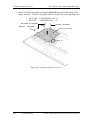
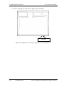
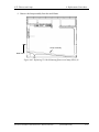
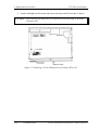
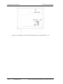
Figure 2-1 Troubleshooting flowchart (2/2)
2-4
[CONFIDENTIAL]
Satellite A50S/TECRA A3X Maintenance Manual (960-534)
2.2 Troubleshooting Flowchart
2 Troubleshooting Procedures
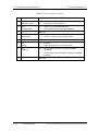
If the diagnostics program cannot detect an error, the problem may be intermittent. The
Test program should be executed several times to isolate the problem. Check the Log
Utilities function to confirm which diagnostic test detected an error(s), then perform the
appropriate troubleshooting procedures as follows:
1. If an error is detected on the system test, memory test, printer test, Async test,
expansion test, real timer test, NDP test or IEEE1394 test, perform the System
Board Troubleshooting Procedures in Section 2.4.
2. If an error is detected on the floppy disk test, perform the FDD Troubleshooting
Procedures in Section 2.5.
3. If an error is detected on the hard disk test, perform the HDD Troubleshooting
Procedures in Section 2.6.
4. If an error is detected on the keyboard test, perform the Keyboard Troubleshooting
Procedures in Section 2.7.
5. If an error is detected on the display test, perform the Display Troubleshooting
Procedures in Section 2.8.
6. If an error is detected on the test for the touch pad function, perform the Touch Pad
Troubleshooting Procedures in Section 2. 9.
7. If an error is detected on the CD-ROM/DVD-ROM test, perform the Optical Drive
Troubleshooting Procedures in Section 2. 10.
8. If an error is detected on the modem test, perform the Modem Troubleshooting
Procedures in Section 2. 11.
9. If an error is detected on the LAN test, perform the LAN Troubleshooting
Procedures in Section 2. 12.
10. If an error is detected on the sound test, perform the Sound Troubleshooting
Procedures in Section 2. 13.
11. If an error is detected on the Wireless LAN test, perform the Wireless LAN
Troubleshooting Procedures in Section 2. 14.
Satellite A50S /TECRA A3X Maintenance Manual (960-534)
[CONFIDENTIAL]
2-5
2 Troubleshooting Procedures
2.3
2.3 Power Supply Troubleshooting
Power Supply Troubleshooting
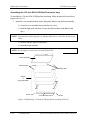
The power supply controller controls many functions and components. To determine if the
power supply is functioning properly, start with Procedure 1 and continue with the other
Procedures as instructed. The procedures described in this section are:
Procedure 1: Power Status Check
Procedure 2: Error Code Check
Procedure 3: Connection Check
Procedure 4: Charging Check
Procedure 5: Replacement Check
Procedure 1
Power Status Check
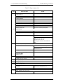
The following icons indicate the power supply status:
? Battery icon
? DC IN icon
The power supply controller displays the power supply status with the Battery icon and the
DC IN icon as listed in the tables below.
Table 2 -1 Battery icon
Battery icon
Power supply status
Lights orange
Battery is charge d and the external DC is input. It has no relation with
ON/OFF of the system power.
Lights green
Battery is fully charged and the external DC is input. It has no relation
with ON/OFF of the system power.
Blinks orange
(even intervals)
The battery level is low while the system power is ON.
Doesn’t light
Any condition other than those above.
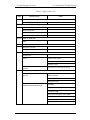
Table 2 -2 DC IN icon
DC IN icon
Power supply status
Lights green
DC power is being supplied from the AC adapter.
Blinks orange
Power supply malfunction
Doesn’t light
Any condition other than those above.
*1
*1 When the power supply controller detects a malfunction, the DC IN icon
blinks orange. It shows an error code.
2-6
[CONFIDENTIAL]
Satellite A50S/TECRA A3X Maintenance Manual (960-534)
2.3 Power Supply Troubleshooting
2 Troubleshooting Procedures
When the icon is blinking, perform the following procedure.
1. Remove the battery pack and the AC adapter.
2. Re-attach the battery pack and the AC adapter.
If the icon is still blinking after the operation above, check the followings:
Check 1
If the DC IN icon blinks orange, go to Procedure 2.
Check 2
If the DC IN icon does not light, go to Procedure 3.
Check 3
If the battery icon does not light orange or green, go to Procedure 4.
NOTE: Use the following supplied AC adapter (G71C0002SB10, G71C0004A410,
G71C00043310, G71C00049310 or G71C00049410).
Satellite A50S /TECRA A3X Maintenance Manual (960-534)
[CONFIDENTIAL]
2-7
2 Troubleshooting Procedures
Procedure 2
2.3 Power Supply Troubleshooting
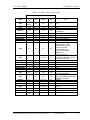
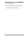
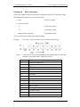
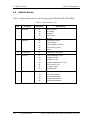
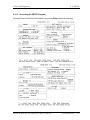
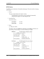
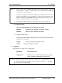
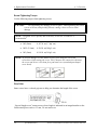
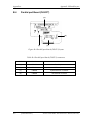
Error Code Check
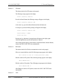
If the power supply microprocessor detects a malfunction, the DC IN icon blinks orange.
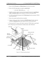
The blink pattern indicates an error as shown below.
? Start
Off for 2 seconds
? Error code (8 bit)
“1”
ON for one second
“0”
ON for half second
Interval between data bits
Off for half second
The error code begins with the least significant digit.
Example:
Error code 13h (Error codes are given in hexadecimal format.)
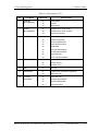
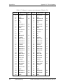
Check 1
Convert the DC IN icon blink pattern into the hexadecimal error code and
compare it to the tables below. Then go to Check 2.
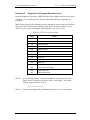
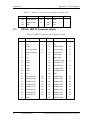
Error code
2-8
Where Error occurs
1*h
Adapter (AC Adapte r, DS)
2*h
1st battery
3*h
2
4*h
S3V output
5*h
E5V output
6*h
E3V output
7*h
PPV output
8*h
1R8-B1V output
9*h
PPV output
A*h
PTV output
B*h
1R5-E1V output
C*h
PGV output
D*h
VG1R8-P1V o utput
E*h
PTV output
F*h
-
[CONFIDENTIAL]
nd
battery
Satellite A50S/TECRA A3X Maintenance Manual (960-534)
2.3 Power Supply Troubleshooting
2 Troubleshooting Procedures
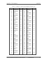
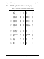
? DC power supply (AC adapter)
Error code
Meaning
10h
AC Adapter output voltage is over 16.5V.
11h
Common Dock output voltage is over 16.5V.
12h
Current from the DC power supply is over 7.00A.
13h
Current from the DC power supply is over 0.5A when there is no load.
14h
Abnormal current has been sensed.
? Main Battery
Error code
Meaning
22h
Main battery discharge current is over 0.5A when there is no load.
23h
Main battery charge current is over 3.9A when AC adapter is not
connected.
24h
Abnormal current has been sensed.
25h
Main battery charge current is over 0.3A.
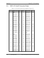
? Second Battery
Error code
Meaning
32h
Second battery discharge current is over 0.5A when there is no load.
33h
Second battery charge current is over 3.9A. when AC adapter is not
connected.
34h
Abnormal current has been sensed.
35h
Second battery charge current is over 0.3A.
? S3V output (P60)
Error code
Meaning
40h
S3V voltage is 3.47 V or less when the computer is powered on/off.
45h
S3V voltage is 3.14 V or less when the computer is powered on.
46h
S3V voltage is 3.14 V or less when the computer is booting up.(CV
support)
Satellite A50S /TECRA A3X Maintenance Manual (960-534)
[CONFIDENTIAL]
2-9
2 Troubleshooting Procedures
2.3 Power Supply Troubleshooting
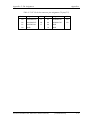
? E5V output (P61)
Error code
Meaning
50h
E5V voltage is over 6.00V when the computer is powered on/off.
51h
E5V voltage is 4.50 V or less when the computer is powered on.
52h
E5V voltage is 4.50 V or less when the computer is booting up.
53h
E5V voltage is over 4.50 V when the computer is powered o ff. (EV power
is off)
54h
E5V voltage is 4.50 V or less when the computer is powered off. (EV
power is on)
? E3V output (P62)
Error code
Meaning
60h
E3V voltage is over 3.96 V when the computer is powered on/off.
61h
E3V voltage is 2.81V or less when the computer is powered on.
62h
E3V voltage is 2.81V or less when the computer is booting up .
63h
E3V voltage is over 2.81 V when the computer is powered o ff. (EV
power is off)
64h
E3V voltage is 2.81V or less when the computer is powered o ff. (EV
power is on)
? 1R5-E1V output (P63: MUX_CH0)
Error code
Meaning
70h
1R5-E1V voltage is over 1.80 V when the computer is powered on/off.
71h
1R5-E1V voltage is 1.275V or less when the computer is powered on.
72h
1R5-E1V voltage is 1.275V or less when the computer is booting up.
73h
1R5-E1V voltage is over 1.275V when the computer is powered off.
(EV p ower is off)
? 1R8-B1V output (P64)
Error code
2-10
Meaning
80h
1R8-B1V voltage is over 3.00V when the computer is powered on/off.
81h
1R8-B1V voltage is 1.53V or less when the computer is powered on.
82h
1R8-B1V voltage is 1.53V or less when the computer is booting up.
83h
1R8-B1V voltage is over 1.53V when the computer is powered off.
84h
1R8-B1V voltage is 1.53V or less when the computer is powered off.
(BV power is on)
[CONFIDENTIAL]
Satellite A50S/TECRA A3X Maintenance Manual (960-534)
2.3 Power Supply Troubleshooting
2 Troubleshooting Procedures
? PPV output (P65)
Error code
Meaning
90h
PPV voltage is over 1.80V when the computer is powered on/off .
91h
PPV voltage is 0.56V or less when the computer is powered on.
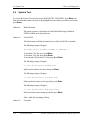
92h
PPV voltage is 0.56V or less when the computer is booting up.
93h
PPV voltage is over 0.56V when the computer is powered off. (PV
power is off)
? PTV output (P66)
Error code
Meaning
A0h
PTV voltage is over 1.26V when the computer is powered on/off.
A1h
PTV voltage is 0.89V or less when the computer is powered on.
A2h
PTV voltage is 0.89V or less when the computer is booting up.
A3h
PTV voltage is over 0.89V or more when the computer is powered off.
(PV power is off)
? 1R5-E1V output (P63: MUX_CH1)
Error code
Meaning
B0h
1R5-E1V voltage is over 1.80 V when the computer is powered on/off.
B1h
1R5-E1V voltage is 1.275V or less when the computer is powered on.
B2h
1R5-E1V voltage is 1.275V or less when the computer is booting up.
B3h
1R5-E1V voltage is over 1.275V when the computer is powered off.
(EV power is off)
B4h
1R5-E1V voltage is 1.275V or less when the computer is powered off.
(EV power is on)
? PTV output (P73)
Error code
Meaning
C0h
PTV voltage is over 1.63 V when the computer is powered on/off.
C1h
PTV voltage is 0.68V or less when the computer is powered on.
C2h
PTV voltage is 0.68V or less when the computer is booting up.
C3h
PTV voltage is over 0.68V when the computer is powered off.
(BV power is on)
C4h
PTV voltage is 0.68V or less when the computer is powered off.
(BV power is on)
Satellite A50S /TECRA A3X Maintenance Manual (960-534)
[CONFIDENTIAL]
2-11
2 Troubleshooting Procedures
2.3 Power Supply Troubleshooting
? PTV output (P75)
Error code
Meaning
D0h
PTV voltage is over 2.16V when the computer is powered on/off.
D1h
PTV voltage is 0.89V or less when the computer is powered on.
D2h
PTV voltage is 0.89V or less when the computer is booting up.
D3h
PTV voltage is 0.89V or more when the computer is powered off.
(PV power is off)
? PTV output (P77: MUX_CH1)
Error code
Meaning
E0h
PTV voltage is over 1.26V when the computer is powered on/off.
E1h
PTV voltage is 0.89V or less when the computer is powered on.
E2h
PTV voltage is 0.89V or less when the computer is booting up.
E3h
PTV voltage is 0.89V or less when the computer is powered off.
(PV power is off)
Check 2
In the case of error code 10h or 12h:
? Make sure the AC adapter and AC power cord are firmly plugged into the
DC IN 15 V socket and wall outlet. If the cables are connected correctly, go
to the following step:
? Connect a new AC adapter and AC power cord. If the error still exists, go to
Procedure 5.
Check 3
In the case of error code 21h:
? Go to Procedure 3.
Check 4
For any other errors, go to Procedure 5.
2-12
[CONFIDENTIAL]
Satellite A50S/TECRA A3X Maintenance Manual (960-534)
2.3 Power Supply Troubleshooting
Procedure 3
2 Troubleshooting Procedures
Connection Check
The wiring diagram related to the power supply is shown below:
Any of the connectors may be disconnected. Perform Check 1.
Check 1
Make sure the AC adapter and the AC power cord are firmly plugged into the
DC IN 15 V socket and wall outlet. If these cables are connected correctly, go
to Check 2.
Check 2
Replace the AC adapter and the AC power cord with new ones.
?
?
Check 3
If the DC IN icon does not light, go to Procedure 5.
If the battery icon does not light, go to Check 3.
Make sure the battery pack is installed in the computer correctly. If the battery
is properly installed and the battery icon still does not light, go to Procedure 4.
Procedure 4
Charging Check
Check if the power supply controller charge s the battery pack properly. Perform the
following procedures:
Check 1
Make sure the AC adapter is firmly plugged into the DC IN socket.
Check 2
Make sure the battery pack is properly installed. If the battery is properly
installed, go to Check 3.
Check 3
The battery pack may be completely discharged. Wait a few minutes to charge
the battery pack while connecting the battery pack and the AC adapter. If the
battery pack is still not charged, go to Check 4.
Check 4
The battery’s temperature is too high or low. Return the temperature to normal
operating condition. If the battery pack is still not charged, go to Check 5.
Check 5
Replace the battery pack with a new one. If the battery pack is still not charged,
go to Procedure 5.
Satellite A50S /TECRA A3X Maintenance Manual (960-534)
[CONFIDENTIAL]
2-13
2 Troubleshooting Procedures
Procedure 5
2.3 Power Supply Troubleshooting
Replacement Check
The power is supplied to the sys tem board by the AC adapter. If either the AC adapter or
the system board was damaged, perform the following Checks.
To disassemble the computer, follow the steps described in Chapter 4, Replacement
Procedures.
Check 1
Replace the AC adapter with a new one. If the AC adapter is still not
functioning properly, perform Check 2.
Check 2
Replace the DC-IN harness with a new one. If the AC adapter is still not
functioning properly, perform Check 2.
Check 3
Replace the system board with a new one.
2-14
[CONFIDENTIAL]
Satellite A50S/TECRA A3X Maintenance Manual (960-534)
2.4 System Board Troubleshooting
2.4
2 Troubleshooting Procedures
System Board T roubleshooting
This section describes how to determine if the system board is defective. Start with
Procedure 1 and continue with the other procedures as instructed. The procedures
described in this section are:
Procedure 1: Message Check
Procedure 2: Debug Port Check
Procedure 3: Diagnostic Test Program Execution Check
Procedure 4: Replacement Check
Satellite A50S /TECRA A3X Maintenance Manual (960-534)
[CONFIDENTIAL]
2-15
2 Troubleshooting Procedures
Procedure 1
2.4 System Board Troubleshooting
Message Check
When the power is turned on, the system performs the Initial Reliability Test (IRT)
installed in the BIOS ROM. The IRT tests each IC on the system board and initializes it.
? If an error message is shown on the display, perform Check 1.
? If there is no error message, go to Procedure 2.
? If MS-DOS or Windows OS is properly loaded, go to Procedure 4.
Check 1
If one of the following error messages is displayed on the screen, press the F1
key as the message instructs. These errors occur when the system configuration
preserved in the RTC memory (CMOS type memory) is not the same as the
actual configuration or when the data is lost.
If you pres s the F1 key as the message instructs, the SETUP screen appears to
set the system configuration. If error message (b) appears often when the power
is turned on, replace the RTC battery. If any other error message is displayed,
perform Check 2.
Check 2
(a)
*** Bad HDD type ***
Check system. Then press [F1] key ......
(b)
*** Bad RTC battery ***
Check system. Then press [F1] key ......
(c)
*** Bad configuration ***
Check system. Then press [F1] key ......
(d)
*** Bad memory size ***
Check system. Then press [F1] key ......
(e)
*** Bad time function ***
Check system. Then press [F1] key ......
(f)
*** Bad check sum (CMOS) ***
Check system. Then press [F1] key ......
(g)
*** Bad check sum (ROM) ***
Check system. Then press [F1] key ......
If the following error message is displayed on the screen, press any key as the
message instructs. If any other error message displays, perform Check 3.
The following error message appears when data stored in RAM under the
resume function is lost because the battery has become discharged or the
system board is damaged. Go to Procedure 3.
WARNING:
RESUME FAILURE.
PRESS ANY KEY TO CONTINUE.
2-16
[CONFIDENTIAL]
Satellite A50S/TECRA A3X Maintenance Manual (960-534)
2.4 System Board Troubleshooting
Check 3
2 Troubleshooting Procedures
The IRT checks the system board. When the IRT detects an error, the system
stops or an error message appears.
If one of the following error messages (1) through (17), (23) or (24) is
displayed, go to Procedure 4.
If error message (18) is displayed, go to the Keyboard Troubleshooting
Procedures in Section 2.7.
If error message (19), (20) or (21) is displayed, go to the 2.5” HDD
Troubleshooting Procedures in Section 2.6.
(1)
(2)
(3)
(4)
(5)
(6)
(7)
(8)
(9)
(10)
(11)
(12)
(13)
(14)
(15)
(16)
(17)
(18)
(19)
(20)
(21)
(22)
(23)
PIT ERROR
MEMORY REFRESH ERROR
TIMER CH.2 OUT ERROR
CMOS CHECKSUM ERROR
CMOS BAD BATTERY ERROR
FIRST 64KB MEMORY ERROR
FIRST 64KB MEMORY PARITY ERROR
VRAM ERROR
SYSTEM MEMORY ERROR
SYSTEM MEMORY PARITY ERROR
EXTENDED MEMORY ERROR
EXTENDED MEMORY PARITY ERROR
DMA PAGE REGISTER ERROR
DMAC #1 ERROR
DMAC #2 ERROR
PIC #1 ERROR
PIC #2 ERROR
KBC ERROR
HDC ERROR
HDD #0 ERROR
HDD #1 ERROR
TIMER INTERRUPT ERROR
RTC UPDATE ERROR
Satellite A50S /TECRA A3X Maintenance Manual (960-534)
[CONFIDENTIAL]
2-17
2 Troubleshooting Procedures
Procedure 2
2.4 System Board Troubleshooting
Debug Port Check
Check the D port status by a debug port test. The tool for debug port test is
shown below.
Figure 2-2 A set of tool for debug port test
The test procedures are follows;
1. Connect the debug test cable to the connector CN3490 of the system board. For
disassembling to connect the test cable, refer to Chapter 4.
2. Connect the debug port test cable and RS-232C cross cable to the test board.
3. Connect the RS-232C cross cable to the PC that displays the results.
4. Boot the computer in MS-DOS mode.
5. Execute GETDPORT.COM in the text menu in CPU REAL mode. (Insert the FD
for starting D port into FDD and input “FD starting drive:>dport”.)
The D port status is displayed in the following form;
6. When the D port status is FFFFh (normal status), go to Procedure 3
7. When the D port status falls into any status in Table 2-3, execute Check 1.
2-18
[CONFIDENTIAL]
Satellite A50S/TECRA A3X Maintenance Manual (960-534)
2.4 System Board Troubleshooting
2 Troubleshooting Procedures
Table 2-3 D port status (1/9 )
D port
status
Inspection items
Details
Enabling address line A20 and Clearing a
software reset bit
Prohibition of APIC
Initializing MCHM
Initializing ICHM
Initializing Super I/O
Initializing debug por t
rd
Dummy read of 3 Bus data
Setting of printer port
F000H
(Only for the model supporting PRT)
BTBK_START
Initializing the CH0 of a PIT
(For HOLD_ON)
Initializing flags determining whether BIOS
is rewritten
CHECK SUM CHECK
Switching to protected mode
Examining the checksum of Boot Block
(Skip when returned to S3)
HLT when check sum error
Examining the checksum other than Boot
Block
F001H
BTBK_CALC_CHKSUM_END
EC/KBC rewrite check
BIOS rewrite when “rewrite” is requested
Transition of the process to System BIOS IRT
when returned to S3
Key input
When inputting key, [
[
],
[TAB] key check
F002H
],
BTBK_INI_SC_START
Initializing security controller
F003H
BTBK_INI_SC_ERR
F004H
BTBK_SC_HW_FAILURE
F005H
BTBK_INI_KBC_END
Checking whether BIOS rewrite is
requested
CheckSum error except Boot Block
when rewrite is requested by user
Transition to BIOS rewrite
F006H
BTBK_ENTER_CHK_BIOS_SIGN
BIOS signature check
Satellite A50S /TECRA A3X Maintenance Manual (960-534)
[CONFIDENTIAL]
2-19
2 Troubleshooting Procedures
2.4 System Board Troubleshooting
Table 2-3 D port status (2/9 )
D port
status
F007H
Inspection items
Details
BTBK_ENTER_SYSTEM_BIOS
Transition to System BIOS IRT
BIOS Rewite process
ICHM.D31 Initialization
DRAM Configuration
Permission of cache () Only for L1 cache
MEMORI CLEAR
F008H
BTBK_INI_MEM_END
Transition to real moded, Copy BIOS in
RAM
F009H
BTBK_CHG_RAM_BIOS
Storing key scan code
Setting up TASK_1ms_TSC
F00AH
BTBK_INI_VGA_END
Controlling Fan
Initializing sound systems (For beep
sound)
Enabling system speaker
Canceling mute
Maximizing volume
When BIOS,EC/KBC is requested to be
rewritten
F00BH
(Green blinks in 2s cycle (ON:1s, Off: 1s))
BTBK_CANT_UPDATE_BIOS
Abnormal BIOS ROM
(Orange blinks in 2s cycle (ON:1s, Off: 1s))
Key input
Disabling USB first
Sound beep
Waiting for key input
Loading
CHGBIOSA.EXE/CHGFIRMA.EXE
FDC RESET
Setting up the parameter for 2HD (1.44MB)
Loading first sector and Confirming the media
if it is 2HD (1.44 MB)
Setting up the parameter for 2DD (720KB)
Searching CHGBIOSA.EXE from route directory
Calculate starting directory head, sector
Loading route directory per sector
2-20
[CONFIDENTIAL]
Satellite A50S/TECRA A3X Maintenance Manual (960-534)
2.4 System Board Troubleshooting
2 Troubleshooting Procedures
Table 2-3 D port status (3/9 )
D port
status
Inspection items
Details
Searching entry of
“CHGBIOSA.EXE/CHGFIRMA.EXE” from the
loaded sector
Loading EXE header of “CHGBIOSA.EXE
/CHGFIRMA.EXE”,
Key input when an error occurred
Executing “CHGBIOSA.EXE”/”CHGFIRMA.EXE”
IRT
F100H
IRT_START
Cache controll for HyperThreading
Disabling cache
Initializing H/W
(before recognizing DRAM)
Initializing MCHM
Initializing ICH4M.D31.Func0
Initializing ICH4M.D31.Func1
Initializing USB.Func0,1,2,7
Initializing ICH4M.D31.Func3
Initializing ICH4M.D31.Func5
Initializing FLUTE
Initializing the channel 1 of a PIT
F101H
(set 30 µs for refresh interval)
IRT_INI_SPREG_END
Checking type and size of DRAM (at
Cold boot only)
When no suport memory is connected, HLT after
beep
HLT when DRAM size is 0
Testing stack area of SM- RAM
F102H
HLT when impossible to use as stack
IRT_STACK_TEST_END
Cache Configuration
Enabling L1 and L2 cache
Access test of CMOS
(at Cold boot only)
(HLT when an error occurred)
Checking battery level of CMOS
CheckSum check of CMOS
Initializing CMOS data (1)
Setting up IRT status
(Setting of Boot status and IRT Busy Flag, The
bit left is 0)
Storing DRAM size
Satellite A50S /TECRA A3X Maintenance Manual (960-534)
[CONFIDENTIAL]
2-21
2 Troubleshooting Procedures
2.4 System Board Troubleshooting
Table 2-3 D port status (4/9 )
D port
status
F103H
Inspection items
Details
IRT_RSM_BRANCH
Resume branch check
(at Cold boot only)
Not resuming when a CMOS error occurred
Not resuming when status code of resume is not
set
Checking resume error
S3 Return error (ICH)
Resume error 170H RSM_UNKNOWN_ERR
Checking CheckSum of SM- RA M
Resume error 173H RSM_SMRAM_ERR
Checking the change of memory configuration
Resume error 174H RSM_SYSTEM_ERR
Checking CheckSum of RAM area of system
BIOS
Resume error 179H RSM_RAMBIOS_ERR
Checking CheckSum of expanded memory
Resume error 176H RSM_EXTMEM_ERR
Checking CheckSum of PnP RAM
Resume error 177H RSM_PNPRAM_ERR
Processing resume (RESUME_MAIN)
Processing resume error
Return the CPU clock to Low
Disabling all SMI
Clearing resume status
Return to ROM
Send the area from C0000h to EFFFFh to PCI
(Disabling DRAM)
Setting up Resume error request
Copy ROM/RAM of the System BIOS
F104H
IRT_BIOS_SIGN_CHK
BIOS signature check
F105H
(HLT when an error occurred)
(at Cold boot only)
IRT_CHG_RAM_BIOS_END
SMRAM initialization
Checking CPU supporting Hyper Threading
Microcode Update
APIC initialization
Checking the factor of WakeUp
Rewriting the SMRAM base and
Storing CPU state map for BIOS
Enabling SMI only by ASMI
2-22
[CONFIDENTIAL]
Satellite A50S/TECRA A3X Maintenance Manual (960-534)
2.4 System Board Troubleshooting
2 Troubleshooting Procedures
Table 2-3 D port status (5/9 )
D port
status
F106H
Inspection items
Details
IRT_INI_SMBASE_END
Initialization of the device Which needs
initialization before PCI BUS Initialization
PCI test (at Cold boot only) and Initialization
Setting test pattern in PIT#0 of Channel 0
Checking whether test pattern set can be
read
Initializing the channel 0 of a PIT
(set 55ms for the interval of interrupt
timer)
Initializing the channel 2 of a PIT
(set 664Hz frequency for sound generator)
Testing the channel 1 of a PIT
(Checking whether refresh signal works
properly with the cycle of refresh interval
30µs), HLT when timeout
Testing the channel 2 of a PIT
(Checking whether speaker gate works
properly)
Measuring the clock speed of a CPU
Permission of SMI except auto-off function
Control the excess of the rated input power
Battery discharge current control (1CmA)
AC adapter rated over current control
Dividing procedures for time measuring of IRT
Setting for clock generator
Checking the parameter block A
Initialization of CPU
Confirming CPU type
Check the support of Geyserville
Set the CPU clock to “High”
F107H
Set Graphics Aperture Size
IRT_CHK_INI_SYS1_END
Storing the configuration of ROM in a
buffer
Reading EC version
Updating the type of flash memory
Determining what country the computer is
designed to be used in by DMI data
Checking the default settings of CMOS
(When finding Bad Battery, Bad
CheckSum (ROM, CMOS), set default)
Initializing ACPI table
(For executing option ROM)
Satellite A50S /TECRA A3X Maintenance Manual (960-534)
[CONFIDENTIAL]
2-23
2 Troubleshooting Procedures
2.4 System Board Troubleshooting
Table 2-3 D port status (6/9 )
D port
status
Inspection items
Details
Initialization of the device needed
initializing before PCI BUS Initialization
AC’97 control
Initializing information of thermal control
Initializing a KBC
Turning VGA display off and controlling reset
Initializing sound func tion
Acquiring the computer multiple box status
HC initialization, Recognition of USB device
connection and initialization
Permission/ prohibition of Built- in LAN control
Initializing a PCI
Testing a PIC
Initializing password
F108H
IRT_CHK_INI_SYS2_END
Initializing PCI Initializing PCI BUS
(connecting DS Bus)
Initializing information of LAN
Checking the factor of WakeUp
F109H
IRT_INI_PCI_END
Running a task of waiting for the end of
INIT_PCI
Initializing the data in CMOS (2)
Initializing PnP
Setting up the setup parameters
Waiting for the end of multiple box state
check
Setting up the hardware parameters
based on resources
F10A H
IRT_MK_SYSRES_END
Running a task of waiting for the end of
PnP resource creation
Serial interrupt control
Initializing PnP hardware
(performed before interrupt)
Initializing PC Card Slots
Initializing SIO (for models supporting SIO)
Initializing FIR (for models supporting FIR)
PCI automatic configuration
Making of work for automatic configuration
Acquisition of PCI IRQ
PCI Configuration
2-24
[CONFIDENTIAL]
Satellite A50S/TECRA A3X Maintenance Manual (960-534)
2.4 System Board Troubleshooting
2 Troubleshooting Procedures
Table 2-3 D port status (7/9 )
D port
status
F10BH
Inspection items
Details
Storing of VGA configuration result
IRT_PCI_CONF_END
Task generation for waiting
PCI_CONFIGURATION completion
Initialization of H/W which is necessary
after PCI configuration
Printer port setting (for models supporting
printer port)
HDD initialization sequence start
FDD initialization sequence start (For models
supporting built-in FDD)
Enabling power off
Output code generation
F10CH
IRT_CHK_INI_SYS3_END
FIRST_64KB_CHECK
F10DH
IRT_CHK_F64KB_END
INIT_INT_VECTOR
F10EH
Initializing interrupt vectors
IRT_INI_VECT_END
INIT_NDP
F10FH
Checking the first 64KB of memory
Initializing a NDP
IRT_INI_NDP_END
INIT_SYSTEM
(Initialization of system)
Storing CMOS error information in
IRT_ERR_STS_BUF
Timer initialization start
Initializing an EC, and reading battery
Updating system BIOS (Updating EDID of
the LCD)
F110H
IRT_INI_SYS_END
INIT_DISPLAY
F111H
(Waiting for VGA chip initialization
completion ? Initializing VGA BIOS)
IRT_VGA_POS_START
VGA POST
F112H
IRT_INI_POST_END
F113H
IRT_INI_DISP_END
(Waiting for VGA chip initialization
completion ? Initializing VGA BIOS)
DISP_LOGO
F114H
IRT_DISP_LOGO_END
SYS_MEM_CHECK
F115H
( Displaying a logo)
Checking conventional memory (Boot)
IRT_SYSTEM_CHK_END
EXT_MEM_CHECK
Exception check in protect mode (Cold boot
only)
Satellite A50S /TECRA A3X Maintenance Manual (960-534)
[CONFIDENTIAL]
2-25
2 Troubleshooting Procedures
2.4 System Board Troubleshooting
Table 2-3 D port status (8/9 )
D port
status
Inspection items
Details
Setting up the address of font data for resume
passwor d
Setting up the parameters for character repeat
on a USB keyboard
Final check of key input during IRT
Storing of T_SHADOW_RAM_SIZE
Update of system resource before boot
Rewriting memory map data for INT15h E820h
function
Waiting for AC- Link initialization completion
Updating of table for DMI
Waiting for AC- Link initialization completion
Waiting for the end of writing PSC version on
BIOS
Waiting for clock generator setting completion
(Stops in “F121H” when an error is detected)
Waiting for the end of serial port initialization
(for models supporting SIO)
Canceling NMI mask
Clearance of the checksum of TIT
Clearing IRT running flag for runtime
Update checksum for runtime
Hibernation branch (for models supporting BIOS
Hibernation)
Initialization of Bluetooth (for models supporting
Bluetooth)
Check of existence of supported maintenance
cards
Prohibition unused PC cards
Setting of WAKEUP status data for ACPI
HW initialization before Boot,
Waiting for initialization completion
F122H
IRT_SC_INIT_START
F123H
IRT_SC_INIT_END
Notify the DVI connection status to VGA
BIOS
(for models supporting DVI)
Setting up battery safe mode
Setting up date
Waiting for the end of Bluetooth
initialization
2-26
[CONFIDENTIAL]
(for models supporting Bluetooth)
Satellite A50S/TECRA A3X Maintenance Manual (960-534)
2.4 System Board Troubleshooting
2 Troubleshooting Procedures
Table 2-3 D port status (9/9)
D port
status
Inspection items
Details
Updating DMI Wakeup factor and SMBIOS structure table
Closing configuration space of PCI devices
Cache control
Update of parameter block A
Process for CPU
Make the CPU clock to be set by SETUP
Waiting for the motor off of a disabled HDD
Final decision
information
of
USB
FDD
drive
Post processing of PRE_BOOT_SETUP
Clearing PWRBTN_STS
Enabling the power button
F124H
IRT_PRE_BOOT_SETUP_END
F125H
IRT_WAIT_DISP_LOGO_START
Clearing IRT status
Updating of checksum for Runtime
FFFFH
IRT_POST_END
Satellite A50S /TECRA A3X Maintenance Manual (960-534)
[CONFIDENTIAL]
2-27
2 Troubleshooting Procedures
Procedure 3
2.4 System Board Troubleshooting
Diagnostic Test Program Execution Check
Execute the following tests from the Diagnostic Test Menu. These tests check the system
board. Refer to Chapter 3, Tests and Diagnostic, for more information on how to perform
these tests.
1. System test
2. Memory test
3. Keyboard test
4. Display test
5. Floppy Disk test
6. Printer test
7. Async test
8. Hard Disk test
9. Real Timer test
10. NDP test
11. Expansion test
12. CD-ROM/DVD-ROM test
13. Only One test
14. Wireless LAN test
15. LAN/Modem/Bluetooth/IEEE1394 test
16. Sound test
If an error is detected during these tests, go to Procedure 4.
Procedure 4
Replacement Check
The system board may be damaged. Disassemble the computer following the steps
described in Chapter 4, Replacement Procedures and replace the system board with a new
one.
2-28
[CONFIDENTIAL]
Satellite A50S/TECRA A3X Maintenance Manual (960-534)
2.5 3.5” FDD Troubleshooting
2 Troubleshooting Procedures
2
2.5
3.5” FDD Troubleshooting
This section describes how to determine if the 3.5” FDD is functioning properly. Perform
the steps below starting with Procedure 1 and continuing with the other procedures as
required.
Procedure 1: FDD Head Cleaning Check
Procedure 2: Diagnostic Test Program Execution Check
Procedure 3: Connector Check and Replacement Check
Procedure 1
FDD Head Cleaning Check
FDD head cleaning is one option available in the Diagnostic Program.
Insert the Diagnostics Disk in the external floppy disk drive, turn on the computer and run
the test. And then clean the FDD heads using the cleaning kit. If the FDD still does not
function properly after cleaning, go to Procedure 2.
Detailed operation is given in Chapter 3, Tests and Diagnostics.
If the test program cannot be executed on the computer, go to Procedure 3.
Satellite A50S /TECRA A3X Maintenance Manual (960-534)
[CONFIDENTIAL]
2-29
2 Troubleshooting Procedures
Procedure 2
2.5 3.5” FDD Troubleshooting
Diagnostic Test Program Execution Check
Insert the Diagnostics Disk in the USB FDD, turn on the computer and run the test. Refer
to Chapter 3, Tests and Diagnostics, for more infor mation about the diagnostics test
procedures.
Make sure the floppy disk is formatted correctly and that the write protect tab is disabled.
Floppy disk drive test error codes and their status names are listed in Table 2-4. If any
other errors occur while executing the FDD diagnostics test, go to Check 1.
Table 2 -4 FDD error code and status
Code
Check 1
Status
01h
Bad command
02h
Address mark not found
03h
Write protected
04h
Record not found
06h
Media replaced
08h
DMA overrun error
09h
DMA boundary error
10h
CRC error
20h
FDC error
40h
Seek error
60h
FDD not drive
80h
Time out error (Not ready)
EEh
Write buffer error
FFh
Data compare error
If the following message is displayed, disable the write protect tab on the
floppy disk by sliding the write protect tab to “write enable”. If any other
message appears, perform Check 2.
Write protected
Check 2
2-30
Make sure the floppy disk is formatted correctly. If it is, go to Procedure 3.
[CONFIDENTIAL]
Satellite A50S/TECRA A3X Maintenance Manual (96 0-534)
2.5 3.5” FDD Troubleshooting
Procedure 3
2 Troubleshooting Procedures
Connector Check and Replacement Check
The USB connector may be disconnected from the system board. Check visually that the
connector is connected firmly.
Check 1
Make sure the following cable s and connectors are firmly connected to the each
board.
(FLGSR PCB)
CN4632
CN4630
USB harness
(FLGCP PCB)
USB FDD
CN4622
System board
CN4620
PJ4611
(FLKCS PCB)
CN4611
CN4612
PJ4610
*
FLGSR PCB? FLGCP PCB or FLKCS
PCB is exclusive choice PCB.
They are never mounted in the
same board at the same time.
System board
USB FDD
CN4610
If any of the connections are loose, reconnect firmly and repeat Procedure 2. If
there is still an error, go to Check 2.
Check 2
The USB FDD may be defective or damaged. Replace it with a new one. If the
FDD is still not functioning properly, perform Check 3.
Check 3
The FLGSR board, FLGCP board or FLGCS board connected to the system
board may be defective or damaged. Replace it with a new one. If the FDD is
still not functioning properly, perform Check 4.
Check 4
Replace the system board with a new one following the steps in Chapter 4,
Replacement Procedures.
Satellite A50S /TECRA A3X Maintenance Manual (960-534)
[CONFIDENTIAL]
2-31
2 Troubleshooting Procedures
2.6
2.6 2.5” HDD Troubleshooting
2.5” HDD Troubleshooting
This section describes how to determine if the 2.5” HDD is functioning properly. Perform
the steps below starting with Procedure 1 and continuing with the other procedures as
required.
Procedure 1: Partition Check
Procedure 2: Message Check
Procedure 3: Format Check
Procedure 4: Diagnostic Test Program Execution Check
Procedure 5: Connector Check and Replacement Check
CAUTION: The contents of the hard disk will be erased when the 2.5 ” HDD
troubleshooting procedures are executed. Transfer the contents of the hard disk to
floppy disks or other storage drive(s). For the backup, refer to the User’s Manual.
Procedure 1
Partition Check
Insert the Toshiba MS-DOS system disk and start the computer. Perform the following
checks:
Check 1
Type C: and press Enter. If you cannot change to drive C, go to Check 2. If
you can change to drive C, go to Procedure 2.
Check 2
Type FDISK and press Enter. Choose Display Partition Information from the
FDISK menu. If drive C is listed in the Display Partition Information, go to
Check 3. If drive C is not listed, return to the FDISK menu and choose the
option to create a DOS partition or a logical DOS drive on drive C. If the
problem still exists, go to Procedure 2.
Check 3
If drive C is listed as active in the FDISK menu, go to Check 4. If drive C is not
listed as active, return to the FDISK menu and choose the option to set the
active partition for drive C. Then go to Procedure 2.
Check 4
Remove the system disk from the FDD and reboot the computer. If the problem
still exists, go to Procedure 2. Otherwise, the 2.5” HDD is operating normally.
2-32
[CONFIDENTIAL]
Satellite A50S/TECRA A3X Maintenance Manual (96 0-534)
2.6 2.5” HDD Troubleshooting
Procedure 2
2 Troubleshooting Procedures
Message Check
When the power is turned on, the system performs the Initial Reliability Test (IRT)
installed in the BIOS ROM. When the test detects an error, an error message is displayed
on the screen.
Make sure of no floppy disk in the FDD. Turn on the computer and check the message on
the screen. When an OS starts from the 2.5” HDD, go to Procedure 3. Other wise, start with
Check 1 below and perform the other checks as instructed.
Check 1
If any of the following messages appear, go to Procedure 3. If the following
messages do not appear, perform Check 2.
HDC ERROR
or
HDD #X ERROR (After 5 seconds this message will disappear.)
Check 2
If either of the following messages appears, go to Check 3. If the following
messages do not appear, perform Check 5.
Insert system disk in drive
Press any key when ready .....
or
Non-System disk or disk error
Replace and pr ess any key when ready
Check 3
Check SETUP to see whether the Hard Disk option is set to Not used. If it is set
to Not used, choose another setting and return to Check 1. If it is not set to Not
used, go to Check 4.
Check 4
Using the SYS command of the MS-DOS, transfer the system to the 2.5” HDD.
If the system is not transferred, go to Procedure 3. Refer to the MS-DOS
Manual for detailed operation.
If the following message appears on the display, the system program has been
transferred to the HDD.
System Transferred
If an error message appears on the display, perform Check 5.
Check 5
The 2.5 ” HDD and the connector of the system board may be disconnected
(Refer to the steps described in Chapter 4, Replacement Procedures for
disassembling.). Insert the connectors firmly. If they are firmly connected, go to
Procedure 3.
Satellite A50S /TECRA A3X Maintenance Manual (960-534)
[CONFIDENTIAL]
2-33
2 Troubleshooting Procedures
Procedure 3
2.6 2.5” HDD Troubleshooting
Format Check
The computer’s HDD is formatted using the MS-DOS FORMAT program or the physical
format program of the test program. To format the HDD, start with Check 1 below and
perfor m the other steps as required.
Refer to the MS-DOS Manual for the operation of MS-DOS. For the format by the test
program, refer to the Chapter 3.
Check 1
Format an 2.5” HDD using MS-DOS FORMAT command. Type as FORMAT
C:/S/U.
If the 2.5” HDD can not be formatted, perform Check 2.
Check 2
Using the MS-DOS FDISK command, set the 2.5” HDD partition. If the
partition is not set, go to Check 3. If it is set, format the 2.5” HDD using MSDOS FORMAT command.
Check 3
Using the Diagnostic Disk, format the 2.5” HDD with a format option (physical
format). If the HDD is formatted, set the 2.5” HDD partition using MS-DOS
FDISK command.
If you cannot format the 2.5 ” HDD using the Tests and Diagnostic program, go
to Procedure 4.
2-34
[CONFIDENTIAL]
Satellite A50S/TECRA A3X Maintenance Manual (96 0-534)
2.6 2.5” HDD Troubleshooting
Procedure 4
2 Troubleshooting Procedures
Diagnostic Test Program Execution Check
The HDD test program is stored in the Diagnostics Disk. Perform all of the HDD tests in
the Hard Disk Drive Test. Refer to Chapter 3, Tests and Diagnostics, for more information
about the HDD test program.
If an error is detected during the HDD test, an error code and status will be displayed. The
error codes and statuses are described in Table 2-5. If an error code is not displayed but the
problem still exists, go to Procedure 5.
Table 2-5 2.5” Hard disk drive error code and status
Code
Status
01h
Bad command
02h
Address mark not found
04h
Record not found
05h
HDC not reset
07h
Drive not initialized
08h
HDC overrun error (DRQ)
09h
DMA boundary error
0Ah
Bad sector error
0Bh
Bad track error
10h
ECC error
11h
ECC recover enable
20h
HDC error
40h
Seek error
80h
Time out error
AAh
Drive not ready
BBh
Undefined error
CCh
Write fault
E0h
Status error
EEh
Access time out error
DAh
No HDD
FFh
Data compare error
Satellite A50S /TECRA A3X Maintenance Manual (960-534)
[CONFIDENTIAL]
2-35
2 Troubleshooting Procedures
Procedure 5
2.6 2.5” HDD Troubleshooting
Connector Check and Replacement Check
The HDD is connected to the connector of the system board. The connecting portion may
be disconnected. Disassemble the computer following the steps described in Chapter 4,
Replacement Procedures and perform the following checks to check the conne cting
portion:
Check 1
Make sure the following connectors are firmly connected to the system board.
44-pin
1st HDD
CN1800
<System board>
If the connection is loose, reconnect firmly and repeat Procedure 1. If there is
still an error, go to Check 2.
Check 2
The 2.5 ” HDD may be damaged. Replace it with a new one following the
instructions in Chapter 4, Replacement Procedures and check the operation. If
the problem still exists, perform Check 3.
Check 3
The system board may be damaged. Replace it with a new one following the
instructions in Chapter 4, Replacement Procedures.
2-36
[CONFIDENTIAL]
Satellite A50S/TECRA A3X Maintenance Manual (96 0-534)
2.7 Keyboard Troubleshooting
2.7
2 Troubleshooting Procedures
Keyboard Troubleshooting
To determine if the computer’s keyboard is functioning properly, perform the following
procedures. Start with Procedure 1 and continue with the other procedures as instructe d.
Procedure 1: Diagnostic Test Program Execution Check
Procedure 2: Connector Check and Replacement Check
Procedure 1
Diagnostic Test Program Execution Check
Execute the Keyboard Test (DIAGNOSTIC TEST) and Pressed key display test (ONLY
ONE TEST) in the Diagnostic Program. Refer to Chapter 3, Tests and Diagnostics, for
more information on how to perform the test program.
If an error occurs, go to Procedure 2. If an error does not occur, keyboard is functioning
properly.
Procedure 2
Connector Check and Replacement Check
The keyboard or system board may be disconnected or damaged. Disassemble the
computer following the steps described in Chapter 4, Replacement Procedures and
perform the following checks:
Check 1
Make sure the keyboard cable is firmly connected to the system board.
34-pin
Keyboard
<System board>
CN3200
If the connection is loose, reconnect firmly and repeat Procedure 1. If there is
still an error, go to Check 2.
Check 2
The keyboard may be damaged. Replace it with a new one following the
instructions in Chapter 4, Replacement Procedures. If the problem still exists,
perform Check 3.
Check 3
The system board may be damaged. Replace it with a new one following the
instructions in Chapter 4, Replacement Procedures.
Satellite A50S /TECRA A3X Maintenance Manual (960-534)
[CONFIDENTIAL]
2-37
2 Troubleshooting Procedures
2.8
2.8 Display Troubleshooting
Display Troubleshooting
To check if the computer’s display is malfunctioning or not, follow the troubleshooting
procedures below as instructed.
Procedure 1: External Monitor Check
Procedure 2: Diagnostic Test Program Execution Check
Procedure 3: Connector and Cable Check
Procedure 4: Replacement Check
Procedure 1
External Monitor Check
Connect an external monitor to the computer’s external monitor port, then boot the
computer. The computer automatically detects the external monitor.
If the external monitor works correctly, the internal LCD may be faulty. Go to Procedure 3.
If the external monitor appears to have the same problem as the internal monitor, system
board may be faulty. Go to Procedure 2.
Procedure 2
Diagnostic Test Program Execution Check
The Display Test program is stored in Diagnostic s disk. This program checks the display
controller on system board. Insert the Diagnostics disk in the USB FDD, turn on the
computer and run the test. Refer to Chapter 3, Tests and Diagnostics for details. If an error
is detected, go to Procedure 3.
2-38
[CONFIDENTIAL]
Satellite A50S/TECRA A3X Maintenance Manual (96 0-534)
2.8 Display Troubleshooting
Procedure 3
2 Troubleshooting Procedures
Connector and Cable Check
LCD Module is connected to system board by an LCD/FL cable. FL inverter board is also
connected to system board by an LCD/FL cable. In addition, fluorescent lamp is connected
to FL inverter board by HV cable. Their cables may be disconnected from system board or
FL inverter board. Disassemble the computer following the steps described in Chapter 4,
Replacement Procedures.
If the connection is loose, reconnect firmly and restart the computer. If the problem still
occurs, go to Procedure 4.
<LCD module>
Fluorescent lamp
LCD/FL cable
HV cable
<FL inverter>
Satellite A50S /TECRA A3X Maintenance Manual (960-534)
<System board>
CN5000
[CONFIDENTIAL]
2-39
2 Troubleshooting Procedures
Procedure 4
2.8 Display Troubleshooting
Replacement Check
Fluorescent lamp, FL inverter, LCD module, HV cable and LCD/FL cable are connected
to display circuits. Any of these components may be faulty. Refer to Chapter 4,
Replacement Procedures, for instructions on how to disassemble the computer and then
perform the following checks:
If fluorescent lamp does not light, perform Check 1.
If characters or graphics on the internal display are not displayed clearly,
perform Check 4.
If some screen functions do not operate properly, perform Check 4.
If fluorescent lamp remains lit when the display is closed, perform Check 5.
Check 1
Replace fluorescent lamp with a new one following the instructions in Chapter
4, Replacement Procedures and test the display again. If the problem still
occurs, perform Check 2.
Check 2
LCD/FL cable may be faulty. Replace FL/LCD cable with a new one following
the instructions in Chapter 4, Replacement Procedure and test the display again.
If the problem still occurs, perform Check 3.
Check 3
FL inverter may be faulty. Replace FL inverter with a new one following the
instructions in Chapter 4, Replacement Procedure and test the display again. If
the problem still occurs, perform Check 4.
Check 4
LCD module may be faulty. Rep lace LCD module with a new one following
the instructions in Chapter 4, Replacement Procedure and test the display again.
If the problem still occurs, perform Check 5.
Check 5
System board may be faulty. Replace it with a new one following the
instructions in Chapter 4, Replacement Procedure.
2-40
[CONFIDENTIAL]
Satellite A50S/TECRA A3X Maintenance Manual (96 0-534)
2.9 Touch Pad Troubleshooting
2.9
2 Troubleshooting Procedures
Touch Pad Troubleshooting
To determine whether the Touch Pad is faulty or not, perform the following procedures:
Procedure 1: Diagnostic Test Program Execution Check
Procedure 2: Connector and Cable Check
Procedure 1 Diagnostic Test Program Execution Check
Execute the Touch pad test (ONLY ONE TEST) in the Diagnostic Program. Refer to
Chapter 3, Tests and Diagnostics, for more information on how to perform the test
program.
If an error occurs, go to Procedure 2. If an error does not occur, touch pad is functioning
properly.
Procedure 2 Connector Check & Replacement Check
Check 1
Make sure the touch pad cable is firmly connected to the system board.
Touch pad
<System board>
CN3240
If the connection is loose, reconnect firmly and repeat Procedure 1. If there is
still an error, go to Check 2.
Check 2
The touch pad or touch pad cable may be damaged. Replace it with a new one
following the instructions in Chapter 4, Replacement Procedures. If the
problem still exists, perform Check 3.
Check 3
The system board may be damaged. Replace it with a new one following the
instructions in Chapter 4, Replacement Procedures.
Satellite A50S /TECRA A3X Maintenance Manual (960-534)
[CONFIDENTIAL]
2-41
2 Troubleshooting Procedures
2.10 Optical Drive Troubleshooting
2.10 Optical Drive Troubleshooting
To check if the optical drive is defective or malfunctioning, follow the troubleshooting
procedures below as instructed.
Procedure 1 Diagnostic Test Program Execution Check
Procedure 2 Connector Check and Replacement Check
Procedure 1
Diagnostic Test Program Execution Check
Execute the CD-ROM/DVD-ROM Test in the Diagnostic Program. Refer to Chapter 3,
Tests and Diagnostics for more information on how to perform the test program.
Prepare the tools before the test. (Refer to tools for implementing the Diagnostics
procedures on page 2-1.)
If any error is detected by the test, go to Procedure 2.
Procedure 2
Connector Check and Replacement Check
The optical drive is connected to the system board by the connector. The connector may
be disconnected from the system board or faulty. Disassemble the computer following the
steps described in Chapter 4 and perform the following checks:
Check 1
Make sure the following connector has been firmly connected to the optical
drive and the system board.
50-pin
Optical
disk drive
<System board>
CN1810
If the connection is loose, reconnect it firmly and return to Procedure 2. If there
is still an error, perform Check 2.
Check 2
The optical drive may be faulty. Replace the optical drive with a new one
following the steps in Chapter 4. If the optical drive is still not functioning
properly, perform Check 3.
Check 3
The system board may be faulty. Replace it with new one following the
instructions in Chapter 4.
2-42
[CONFIDENTIAL]
Satellite A50S/TECRA A3X Maintenance Manual (96 0-534)
2.11 Modem Troubleshooting
2 Troubleshooting Procedures
2.11 Modem Troubleshooting
To check if the modem is defective or malfunctioning, follow the troubleshooting
procedures below as instructed.
Procedure 1 Diagnostic Test Program Execution Check
Procedure 2 Connector Check and Replacement Check
Procedure 1
Diagnostic Test Program Execution Check
Execute Modem test in the LAN/Modem/Bluetooth/IEEE1394 test program. Refer to
Chapter 3, Tests and Diagnostics for more information on how to perform the test program.
If any error is detected, perform Procedure 2.
Procedure 2
Connector Check and Replacement Check
An MDC (Modem Daughter Card) is used as the modem for this computer. The MDC is
connected to the system board by connector. If the modem malfunctions, the se connections
may be bad or the MDC or system board might be faulty.
Disassemble the computer following the steps described in Chapter 4 and perform the
following checks:
Check 1
Make sure the MDC has been firmly connected to the CN3010 on the system
board and the modem harness has been firmly connected to the both connectors
on the system board and on the modem.
Modem
jack
MDC
12-pin
Modem harness
CN3011
CN3010
System board
If any connector is disconnected, connect it firmly and return to Procedure 1. If
there is st ill an error, perform Check 2.
Check 2
The Modem jack may be faulty. Replace it with a new one. If the modem
function is still not working properly, perform Check 3.
Check 3
The MDC may be faulty. Replace it with a new one following the steps in
Chapter 4. If the modem function is still not working properly, perform Check
4.
Check 4
The system board may be faulty. Replace it with a new one following the
instructions in Chapter 4
Satellite A50S /TECRA A3X Maintenance Manual (960-534)
[CONFIDENTIAL]
2-43
2 Troubleshooting Procedures
2.12 LAN Troubleshooting
2.12 LAN Troubleshooting
To check if the computer’s LAN is defective or malfunctio ning, follow the troubleshooting
procedures below as instructed.
Procedure 1 Diagnostic Test Program Execution Check
Procedure 2 Connector Check and Replacement Check
Procedure 1
Diagnostic Test Program Execution Check
Execute LAN test in the LAN/Modem/Bluetooth/IEEE1394 test program. Refer to Chapter
3, Tests and Diagnostics for more information on how to perform the test program.
If any error is detected by the test, go to Procedure 2.
Procedure 2
Connector Check and Replacement Check
The LAN function is operated by the system board via LAN harness. If the LAN
malfunctions, the connection among LAN cable, LAN harness and system board is bad or
they might be faulty.
Disassemble the computer following the steps described in Chapter 4 and perform the
following checks:
Check 1
Check if the LAN cable and LAN harness are connected firmly to the
connectors.
LAN harness
CN4100
LAN cable
<System board>
If they are loose or disconnected, connect it firmly and return to Procedure 1. If
there is still an error, perform Check 2.
Check 2
The LAN cable may be defective. Replace the LAN cable with a new one. If
the problem persist, perform Check 3.
Check 3
The LAN harness may be defective. Replace the LAN harness with a new one.
If the problem persist, perform Check 4.
Check 3
The system board may be faulty. Disassemble the computer following the steps
described in Chapter 4.
2-44
[CONFIDENTIAL]
Satellite A50S/TECRA A3X Maintenance Manual (96 0-534)
2.13 Sound Troubleshooting
2 Troubleshooting Procedures
2.13 Sound Troubleshooting
To check if the sound function is defective or malfunctioning, follow the troubleshooting
procedures below as instructed.
Procedure 1 Diagnostic Test Program Execution Check
Procedure 2 Connector Check
Procedure 3 Replacement Check
Procedure 1
Diagnostic Test Program Execution Check
Execute the Sound Test in the Diagnostic Program. Refer to Chapter 3, Tests and
Diagnostics for more information on how to perform the test program.
If any error is detected by the test, go to Procedure 2
Procedure 2
Connector Check
The connection of sound system is shown in the following figure.
Speaker R
Speaker L
CN6002
<System board>
CN6001 CN9500
Sound board cable
CN9510
J6310
Headphone
<sound board>
J6070
Ext. microphone
As the connection may be bad, disassemble the PC and check each connection.
If the speakers do not work properly, go to Check 1.
If the headphone or external microphone does not work properly, go to Check 2.
Check 1
Make sure the speaker cables are firmly connected to CN6001 and CN6002 on
the system board. If the sound function does not still work properly, perform
Procedure 3.
Check 2
Make sure the sound board is firmly connected to the system board via sound
board cable. If each function does not still work properly, perform Check 2 of
Procedure 3.
Satellite A50S /TECRA A3X Maintenance Manual (960-534)
[CONFIDENTIAL]
2-45
2 Troubleshooting Procedures
Procedure 3
2.13 Sound Troubleshooting
Replacement Check
Check 1
The speaker may be faulty. Replace it with a new one following the steps in
Chapter 4. If the problem persists, perform Check 3.
Check 2
The sound board may be faulty. Replace it with a new one following the steps
in Chapter 4. If the problem persists, perform Check 3.
Check 3
The system board may be faulty. Replace it with a new one following the
instructions in Chapter 4.
2-46
[CONFIDENTIAL]
Satellite A50S/TECRA A3X Maintenance Manual (96 0-534)
2.14 Wireless LAN Troubleshooting
2 Troubleshooting Procedures
2.14 Wireless LAN Troubleshooting
To check if the computer's Wireless LAN is malfunctioning or not, follow the
troubleshooting procedures below as instructed.
Procedure 1: Transmitting-Receiving Check
Procedure 2: Antennas' Connection Check
Procedure 3: Replacement Check
Procedure 1
Transmitting-Receiving Check
Before starting the test, make sure the wireless communication switch is set in the ON
position.
Check 1
Execute Wireless LAN test program to check the transmitting-receiving
function of wireless LAN. You will need a second computer that can
communicate by wireless LAN. Perform the test followin g the instructions
described in Chapter 3.
If the computer passes the test, the function is correctly working. If the
computer does not pass the test, perform Procedure 2.
Procedure 2
Antennas' Connection Check
The wireless LAN function-wiring diagram is shown below:
Wireless LAN
Antenna
(MAIN)
Wireless LAN
Antenna
(AUX)
Wireless
LAN card
<System board>
CN2200
Wirelss LAN antenna cable
Any of the connections may be disconnected. Disassemble the computer following the
steps described in Chapter 4, Replacement Procedures, and perform the following checks:
Check 1
Make sure the wireless communication switch is “On”.
If the switch is “Off”, turn it “On”. If there is still an error, perform Check 2.
Check 2
Make sure the Wireless LAN card is firmly connected to the CN2200 on the
system board.
If the connector is disconnected, connect it firmly and perform Procedure 1. If
the Wireless LAN is still not functioning properly, perform Check 3.
Satellite A50S /TECRA A3X Maintenance Manual (960-534)
[CONFIDENTIAL]
2-47
2 Troubleshooting Procedures
Check 3
2.14 Wireless LAN Troubleshooting
Make sure the wireless LAN antenna cables (MAIN and AUX) are firmly
connected to the connectors on the wirelss LAN card.
If the wireless LAN antenna cables are disconnected, connect them firmly and
perform Procedure 1. If the wireless LAN is still not functioning properly, go to
Procedure 3.
Procedure 3
Replacement Check
The wirelss LAN card, wireless LAN antennas and the system board are may be damaged.
Refer to Chapter 4, Replacement Procedures, for instructions on how to disassemble the
computer and then perform the following checks:
Check 1
The wireless LAN card may be defective or damaged. Replace the wireless
LAN card with a new one following the instructions in Chapter 4, Replacement
Procedures. If the problem still exists, perform Check 2.
Check 2
The wireless LAN antennas may be defective or damaged. Replace the wireless
LAN antennas with a new one following the instructions in Chapter 4,
Replacement Procedures. If the problem still exists, perform Check 3.
Check 3
Replace the system board with a new one following the instructions in Chapter
4, Replacement Procedures and test the display again.
2-48
[CONFIDENTIAL]
Satellite A50S/TECRA A3X Maintenance Manual (96 0-534)
Chapter 3
Tests and Diagnostics
[CONFIDENTIAL]
3 Tests and Diagnostics
3
3-ii
[CONFIDENTIAL]
Satellite A50S/TECRA A3X Maintenance Manual (960-534)
3 Tests and Diagnostics
Chapter 3
3.1
3.2
Contents
The Diagnostic Test ................................................................................................... 3-1
3.1.1
Diagnostics menu ................................................................................. 3-1
3.1.2
H/W (Hardware) initial information setting tool.................................. 3-3
3.1.3
Heatrun test program............................................................................ 3-3
Executing the Diagnostic Test ................................................................................... 3-4
3.2.1
Diagnostics menu (T&D) ..................................................................... 3-4
3.2.2
H/W initial information setting tool ..................................................... 3-7
3.2.3
Heatrun test program............................................................................ 3-7
3.3
Setting of the hardware configuration........................................................................ 3-8
3.4
Heatrun Test ............................................................................................................. 3-11
3.5
Subtest Names.......................................................................................................... 3-12
3.6
System Test.............................................................................................................. 3-14
3.7
Memory Test............................................................................................................ 3-16
3.8
Keyboard Test.......................................................................................................... 3-17
3.9
Display Test ............................................................................................................. 3-18
3.10
Floppy Disk Test ...................................................................................................... 3-21
3.11
Printer Test ............................................................................................................... 3-23
3.12
Async Test................................................................................................................ 3-25
3.13
Hard Disk Test ......................................................................................................... 3-26
3.14
Real Timer Test........................................................................................................ 3-29
3.15
NDP Test.................................................................................................................. 3-31
3.16
Expansion Test ......................................................................................................... 3-32
3.17
CD-ROM/DVD-ROM Test ..................................................................................... 3-34
3.18
Error Code and Error Status Names......................................................................... 3-35
3.19
Hard Disk Test Detail Status .................................................................................... 3-38
3.20
ONLY ONE TEST................................................................................................... 3-40
3.21
3.20.1
Program Description........................................................................... 3-40
3.20.2
Operations ........................................................................................... 3-40
Head Cleaning.......................................................................................................... 3-46
3.21.1
Function Description.......................................................................... 3-46
Satellite A50S/TECRA A3X Maintenance Manual (960-534)
[CONFIDENTIAL]
3-iii
3 Tests and Diagnostics
3.21.2
3.22
3.23
3.24
3.25
Operations ........................................................................................... 3-46
Log Utilities ............................................................................................................. 3-47
3.22.1
Function Description.......................................................................... 3-47
3.22.2
Operations ........................................................................................... 3-48
Running Test............................................................................................................ 3-49
3.23.1
Function Description.......................................................................... 3-49
3.23.2
Operations ........................................................................................... 3-49
Floppy Disk Drive Utilities...................................................................................... 3-50
3.24.1
Function Description.......................................................................... 3-50
3.24.2
Operations ........................................................................................... 3-51
System Configuration .............................................................................................. 3-55
3.25.1
Function Description.......................................................................... 3-55
3.25.2
Operations ........................................................................................... 3-56
3.26
Wireless LAN Test Program (Intel- made b/g) ......................................................... 3-57
3.27
Wireless LAN Test Program (Intel- made a/b/g)...................................................... 3-61
3.28
Wireless LAN Test Program (Askey- made) ............................................................ 3-66
3.29
LAN/Modem/Bluetooth/IEEE1394 Test Program .................................................. 3-70
3.30
3.31
3-iv
3.29.1
LAN test ............................................................................................. 3-70
3.29.2
Modem test ......................................................................................... 3-73
3.29.3
Bluetooth test ...................................................................................... 3-74
3.29.4
IEEE1394 test..................................................................................... 3-83
Sound Test program................................................................................................. 3-84
3.30.1
Sound (Standard) test ......................................................................... 3-84
3.30.2
Sound (Legacy) test............................................................................ 3-86
3.30.3
CD Sound (Standard) test ................................................................... 3-87
3.30.4
CD Sound (Legacy) test ..................................................................... 3-89
SETUP ..................................................................................................................... 3-90
3.31.1
Function Description.......................................................................... 3-90
3.31.2
Accessing the SETUP Program.......................................................... 3-92
[CONFIDENTIAL]
Satellite A50S/TECRA A3X Maintenance Manual (960-534)
3 Tests and Diagnostics
Tables
Table 3-1 Subtest names .................................................................................................... 3-12
Table 3-2 Error codes and error status names .................................................................... 3-35
Table 3-3 Hard disk controller status register contents ...................................................... 3-38
Table 3-4 Error register contents ........................................................................................ 3-39
Table 3-5 Error message ..................................................................................................... 3-76
Table 3-6 Error code for Bluetooth test (BD_ADDR) ....................................................... 3-77
Table 3-7 Error code for Bluetooth test (BD_ADDR of the DUT).................................... 3-81
Satellite A50S/TECRA A3X Maintenance Manual (960-534)
[CONFIDENTIAL]
3-v
3 Tests and Diagnostics
3.1 The Diagnostic Test
3
3.1
The Diagnostic Test
This chapter explains how to use the Diagnostic Test programs to test the functions of the
computer’s hardware modules. The Diagnostics Programs are stored on some Diagnostic Disks.
There are Service Program Modules (DIAGNOSTIC MENU) and the Test Program Modules
(DIAGNOSTIC TEST MENU) on the Diagnostic Disk.
The Hardware Initial information Setting Tool consists of some programs that write the hardware
information or displays the current information of the computer. It is also included in one of
Diagnostic Disks.
The heatrun test is automatic test program that executes the some tests successively.
NOTE: Before starting the diagnostics, be sure to follow these steps:
1. Check all cables are connected firmly.
2. Exit any application and close Windows.
3. Check if [ALL Device] is selected in the “Device Config.” in SET UP menu.
After checking the diagnostics, be sure to select [Setup by OS] in the
“Device Config.”
When replacing the system board, be sure to execute the following procedures.
1. Before replacing the system board, execute subtest03 "DMI information
save" in 3.3 Setting of the hardware configuration in order to save the DMI
information from system board to floppy disk.
2. After replacing the system board, execute the subtest04 "DMI information
recovery" and subtest08 "System configuration display" in 3.3 Setting of the
hardware configuration in order to copy the DMI information and system
information from the floppy disk.
3.1.1 Diagnostics menu
The DIAGNOSTIC MENU consists of the following functions.
?
?
?
?
?
?
DIAGNOSTIC TEST
ONLY ONE TEST
HEAD CLEANING
LOG UTILITIES
RUNNING TEST
FDD UTILITIES
Satellite A50S/TECRA A3X Maintenance Manual (960-534)
[CONFIDENTIAL]
3-1
3.1 The Diagnostic Test
3 Tests and Diagnostics
? SYSTEM CONFIGURATION
? EXIT TO MS-DOS
The DIAGNOSTIC TEST MENU contains the following functional tests:
?
?
?
?
?
?
?
?
?
?
?
?
SYSTEM TEST
MEMORY TEST
KEYBOARD TEST
DISPLAY TEST
FLOPPY DISK TEST
PRINTER TEST
ASYNC TEST
HARD DISK TEST
REAL TIMER TEST
NDP TEST
EXPANSION TEST
CD-ROM/DVD-ROM TEST
Other tests are:
? Wireless LAN TEST (Wireless LAN TEST disk)
? LAN/Modem/Bluetooth/IEEE1394 TEST (LAN/Modem/Bluetooth/IEEE1394 TEST disk)
? Sound TEST (Sound TEST disk)
You will need the following equipment to perform some of the Diagnostic test programs.
? USB FDD
? The Diagnostic Disks (T&D for maintenance, LAN/Modem/Bluetooth/IEEE1394 for
maintenance, wireless LAN for maintenance and Sound for maintenance)
? A formatted working disk (Floppy disk test)
? A cleaning kit to clean the floppy disk drive heads (Head Cleaning)
? An external display supporting monitor ID (Expansion test)
? A CD test media TOSHIBA CD-ROM TEST DISK or ABEX TEST CD-ROM (Sound
test)
? A DVD test media (DVD-ROM TEST DISK TSD-1) (Sound test)
? A music CD (Sound test)
? A CD-RW test media (CD-ROM/DVD-ROM test)
? A USB test module (USB test )
? A USB cable (USB test)
? LAN wraparound connector (LAN test)
? RGB wraparound connector (Expansion test)
? Module cable and RJ11 connector checker (Modem test)
? Headphones (Sound test)
? A microphone (Sound test)
3-2
[CONFIDENTIAL]
Satellite A50S/TECRA A3X Maintenance Manual (960-534)
3 Tests and Diagnostics
3.1 The Diagnostic Test
? A PC for wraparound test (Wireless LAN test/Bluetooth test/IEEE1394 test)
? PC card wraparound connector (Expansion test)
Satellite A50S/TECRA A3X Maintenance Manual (960-534)
[CONFIDENTIAL]
3-3
3.1 The Diagnostic Test
3 Tests and Diagnostics
3.1.2 H/W (Hardware) initial information setting tool
The H/W initial information setting tool consists of the following programs.
?
?
?
?
Initial configuration
Region write
System configuration display
E2PROM test (MAC/GUID/DMI)
You will need the following equipment to perform some of the programs.
? The Diagnostics Disk (Main T&D)
? A LAN wraparound connector (E2PROM test)
3.1.3 Heatrun test program
The heatrun test starts automatically after the selection.
You will need the following equipment to perform this program.
? The Diagnostics Disk (Main T&D)
3-4
[CONFIDENTIAL]
Satellite A50S/TECRA A3X Maintenance Manual (960-534)
3 Tests and Diagnostics
3.2
3.2 Executing the Diagnostic Test
Executing the Diagnostic Test
To start the DIAGNOSTIC PROGRAM, follow these steps:
1. Insert the Diagnostics disk in the floppy disk drive.
2. Release the lock of the power switch and turn on the computer with pressing the F12.
Select the FDD in the display for selecting booting unit. Then, press Enter and the
following menu appears.
Microsoft Windows XX Startup Menu
--------------------------------------------------------1. Repair Main (T&D)
2. Repair initial config set
3. Repair Heatrun (T&D)
Enter a choice: 1
To start the Diagnostics menu (T&D), press 1 and Enter .
To start the H/W initial information setting tool, press 2 and Enter.
To start the Heatrun test, press 3 and Enter.
3.2.1 Diagnostics menu (T&D)
After pressing 1 and Enter in the startup menu, the following menu appears.
TOSHIBA personal computer XXXXXX DIAGNOSTICS
version X.XX (c) copyright TOSHIBA Corp. 20XX
DIAGNOSTICS MENU :
1
2
3
4
5
6
7
8
9
–
-
DIAGNOSTIC TEST
ONLY ONE TEST
HEAD CLEANING
LOG UTILITIES
RUNNING TEST
FDD UTILITIES
SYSTEM CONFIGURATION
EXIT TO MS-DOS
Satellite A50S/TECRA A3X Maintenance Manual (960-534)
[CONFIDENTIAL]
3-5
3.2 Executing the Diagnostic Test
3 Tests and Diagnostics
NOTE: To exit the DIAGNOSTIC TEST MENU, press the Esc key. If a test program is in
progress, press Ctrl + Break to exit the test program. If a test program is in
progress, press Ctrl + C to stop the test program.
Set the highlight bar to 1, and press Enter. The following DIAGNOSTIC TEST MENU will
appear:
TOSHIBA personal computer XXXXXX DIAGNOSTICS
version X.XX (c) copyright TOSHIBA Corp. 20XX
DIAGNOSTIC TEST MENU :
1
2
3
4
5
6
7
8
9
10
11
12
88
99
–
-
SYSTEM TEST
MEMORY TEST
KEYBOARD TEST
DISPLAY TEST
FLOPPY DISK TEST
PRINTER TEST
ASYNC TEST
HARD DISK TEST
REAL TIMER TEST
NDP TEST
EXPANSION TEST
CD-ROM/DVD-ROM TEST
ERROR RETRY COUNT SET [FDD & HDD]
EXIT TO DIAGNOSTICS MENU
Functions 1 through 12 are the Diagnostic Tests. Function 88 sets the floppy disk drive and
hard disk drive error retry count (0-255).
To exit the submenu of the Diagnostic Test and returns to the Diagnostics Menu, set the
highlight bar to function 99 and press Enter.
3-6
[CONFIDENTIAL]
Satellite A50S/TECRA A3X Maintenance Manual (960-534)
3 Tests and Diagnostics
3.2 Executing the Diagnostic Test
Select the option you want to execute and press Enter. When you select 1- SYSTEM TEST,
the following message will appear:
SYSTEM TEST NAME
SUB-TEST
PASS COUNT
WRITE DATA
ADDRESS
:
:
:
:
XX
XXXXX
XX
XXXXXX
XXXXXX
xxxxxxx DIAGNOSTIC TEST VX.XX
[Ctrl]+[Break] ; test end
[Ctrl]+[C]
; key stop
ERROR COUNT: XXXXX
READ DATA : XX
STATUS
: XXX
SUB-TEST MENU :
01
02
03
04
05
99
–
-
ROM checksum
Fan ON/OFF
Geyserville
Quick charge
DMI read
Exit to DIAGNOSTIC TEST MENU
NOTE: The menu displayed by your computer may be slightly different from the one
shown above.
Select the desired subtest number from the subtest menu and press Enter. The following message
will appear:
TEST LOOP : YES (or NO)
ERROR STOP : YES (or NO)
Use the right and left arrow keys to move the cursor to the desired option.
Selecting YES of TEST LOOP increases the pass counter by one, each time the test cycle ends
and restarts the test cycle.
Selecting NO returns the process to the subtest menu after the test is complete.
Satellite A50S/TECRA A3X Maintenance Manual (960-534)
[CONFIDENTIAL]
3-7
3.2 Executing the Diagnostic Test
3 Tests and Diagnostics
Use the up and down arrow keys to move the cursor to “ERROR STOP”.
Use the right and left arrow keys to move the cursor to the desired option and press Enter.
Selecting YES of ERROR STOP stops the test program when an error is found and displays the
operation guide on the right side of the display screen as shown below:
ERROR STATUS NAME
[[ HALT OPERATION ]]
1: Test end
2: Continue
3: Retry
These three selections have the following functions respectively:
1. Terminates the test program and exits to the subtest menu.
2. Continues the test.
3. Restarts the test from the error.
Selecting NO keeps the test running even if an error is found. When an error occurred, the error
status is displayed and one error is added to the error counter.
Table 3-1 in section 3.5 describes the function of each test on the subtest menu. Table 3-2 in
section 3.19 describes the error codes and error status for each error.
3.2.2 H/W initial information setting tool
After selecting this test, the following menu appears in the display.
##################################################################
#
######
H/W initial information setting tool
VX.XX
######
##################################################################
#
*
1 ………………………… Initial configuration
*
*
2 ………………………… Region write
*
*
3 ………………………… DMI information save
*
*
4 ………………………… DMI information recovery
*
*
8 ………………………… System configuration display
*
*
9 ………………………… E2PROM test (MAC/GUID/DMI)
*
******************************************************************
*
... Press test number[1-4,8,9] ?
For more details on this test, refer to the section 3.4.
3-8
[CONFIDENTIAL]
Satellite A50S/TECRA A3X Maintenance Manual (960-534)
3 Tests and Diagnostics
3.2 Executing the Diagnostic Test
3.2.3 Heatrun test program
Heatrun test starts executing the same subtest as 3.24 RUNNING TEST.
For more details on this test, refer to the section 3.4.
Satellite A50S/TECRA A3X Maintenance Manual (960-534)
[CONFIDENTIAL]
3-9
3.3 Setting of the hardware configuration
3.3
3 Tests and Diagnostics
Setting of the hardware configuration
To execute this program, select 2-Repair initial config test in the startup menu,
press Enter and follow the directions on the screen. The H/W initial information setting tool
consists of four subtests. Move the highlight bar to the subtest you want to execute and press
Enter.
Subtest 01
Initial configuration
This subtest executes the following items and shows their contents in the display.
When an item ends normally, the program proceeds automatically to the next one.
When an error is found, the program stops and waits for key input. (After solving
the problem, the program executes the item again.)
Setting of the CPU set table
Setting of the micro code
Setting of the EHSS
Inputting and writing of DMI information
When the DMI information is displayed,
the following messages appear
in order. Input each information. (If you do not replace the PCB, the DMI
information should not be changed.)
1. “Enter Model Name?” is displayed. Input the computer’s model name
and press Enter. (e.g. DynaBook)
2. “Enter Version Number?” is displayed. Input the computer’s version
number and press Enter. (e.g. PC18070C313S)
3.
“Enter Serial Number?” is displayed. Input the computer’s serial
number and press Enter. (e.g. 12345678)
4. “Enter Model Number?” is displayed. Input the computer’s sales model
number and press Enter. (e.g. PP200-AAAAA)
5.
“Enter Bundle Number?” is displayed. Input the computer’s
PCN/Bundle number and press Enter.
(e.g. PMSREQ3Q34H/S0123456789)
6. “Write data OK (Y/N)?” is displayed. To write the DMI information to
the Flash ROM, press Y, and then Enter.
7. “Create DMIINFO TXT (Y/N)?” is displayed. Press Y, then the DMI
information (text data) is written to the Floppy disk, etc.
3-10
[CONFIDENTIAL]
Satellite A50S/TECRA A3X Maintenance Manual (960-534)
3 Tests and Diagnostics
3.3 Setting of the hardware configuration
Setting of the HWSC
Setting of the UUID
Display of the DMI information (including UUID)
Setting of DVD region code (Yes/No)
After completion of the above settings, H/W configuration & DMI information are
appeared in order. Check the contents and press Enter.
Subtest 02
Region write
This subtest executes the setting of the region code for DVD drive based on the
destination of the machine.
When the region code is already written, test ends without setting.
The following message appears in the display after setting the region code. Press
any key to return to the H/W initial information setting tool menu.
***********************************
*******
It completed
*******
***********************************
*
*
Press any key to continue...
Subtest 03
DMI information save
NOTE: Before replacing the system board, be sure to execute this subtest and save the
DMI information to the floppy disk.
This is one of tools to copy the DMI information to a new PCB after replacing.
This subtest saves all the DMI data in a floppy disk.
Subtest 04
DMI information recovery
NOTE: 1. After replacing the system board, be sure to execute this subtest and copy the
DMI information to a new system board.
2. Since the data of UUID is updated every time when this subtest, DMI
information recovery, is done, the saved UUID data is not written
This is one of tools to copy the DMI information to a new PCB after replacing.
This subtest writes all the DMI data in the floppy disk into the new PCB.
Satellite A50S/TECRA A3X Maintenance Manual (960-534)
[CONFIDENTIAL]
3-11
3.3 Setting of the hardware configuration
Subtest 08
3 Tests and Diagnostics
System configuration display
This subtest displays the information of the system configuration.
Confirm the contents and press Enter.
For more details on the system configuration information, refer to 3.26 "System
configuration".
Subtest 09
E2PROM test (MAC/GUID/DMI)
It checks whether the MAC address, GUID of IEEE1394 and DMI
information are written.
3-12
[CONFIDENTIAL]
Satellite A50S/TECRA A3X Maintenance Manual (960-534)
3 Tests and Diagnostics
3.4
3.4 Heatrun Test
Heatrun Test
To execute this program, select 3-Repair heatrun in the startup menu, press Enter.
After selecting this test, the same subtests as 3.24 RUNNING TEST is executed successively.
For more details on the procedure and test content, refer to RUNNING TEST.
When the heatrun test ends, following message appears in the display.
************************************************
HEATRUN TEST END
************************************************
Press any key to continue...
Press any key and return to the startup menu.
NOTE: The test result (Errorlog.txt) is stored in the floppy disk. The result is displayed in
the same way as 3.23 LOG UTILITIES. For more detail in the display, refer to
LOG UTILITIES.
Satellite A50S/TECRA A3X Maintenance Manual (960-534)
[CONFIDENTIAL]
3-13
3.5 Subtest Names
3.5
3 Tests and Diagnostics
Subtest Names
Table 3-1 lists the subtest names for each test program in the DIAGNOSTIC TEST MENU.
Table 3-1 Subtest names (1/2)
No.
1
2
SYSTEM
MEMORY
Subtest No.
Subtest Name
01
ROM checksum
02
Fan ON/OFF
03
Geyserville
04
Quick charge
05
01
DMI read
Conventional memory
02
Protected Mode
03
Protected Mode (cache off)
04
Cache memory (on/off)
05
Stress
3
KEYBOARD
01
Pressed key code display
4
DISPLAY
01
VRAM read/write for VGA
02
Gradation for VGA
03
Gradation for LCD
04
Gradation & Mode test for VGA
05
All dot on/off for LCD
06
“H” pattern display
07
LCD Brightness
01
Sequential read
02
Sequential read/write
03
Random address/data
04
Write specified address
05
Read specified address
5
3-14
Test Name
FLOPPY DISK
[CONFIDENTIAL]
Satellite A50S/TECRA A3X Maintenance Manual (960-534)
3 Tests and Diagnostics
3.5 Subtest Names
Table 3-1 Subtest names (2/2)
No.
6
7
8
9
Test Name
PRINTER
[Not supported]
ASYNC
[Not supported]
HARD DISK
REAL TIMER
Subtest No.
Subtest Name
01
Ripple pattern
02
Function
03
Wrap around
01
FIR/SIR Point to point (send)
02
FIR/SIR Point to point (receive)
03
Wrap around (board)
01
Sequential read
02
Address uniqueness
03
Random address/data
04
Cross talk & peak shift
05
Partial Read
06
Write specified address
07
Read specified address
08
Sequential write
09
W-R-C specified address
01
Real time
02
Backup memory
03
Real time carry
10
NDP
01
NDP test
11
EXPANSION
01
PCMCIA wrap around [Not supported]
03
RGB monitor ID
01
Sequential read
02
Read specified address
03
Random address/data
04
RW 1point W/R/C
13
CD-ROM
/DVD-ROM
Satellite A50S/TECRA A3X Maintenance Manual (960-534)
[CONFIDENTIAL]
3-15
3.6 System Test
3.6
3 Tests and Diagnostics
System Test
To execute the System Test select 1 from the DIAGNOSTIC TEST MENU, press Enter and
follow the directions on the screen. Move the highlight bar to the subtest you want to execute and
press Enter.
Subtest 01
ROM Checksum
This subtest executes a checksum test of the BIOS ROM (range: F0000h to
FFFFFh, 64KB) on the System Board.
Subtest 02
Fan ON/OFF
This subtest turns on/off the fan motor by force with Fan ON/OFF commands.
The following message will appear.
Fan number select (1;FAN#1, 2;FAN#2, 0; FAN#1) ?
To check the CPU fan, press 1 and Enter.
To check the VGA fan, press 2 and Enter.
To check both CPU fan and VGA fan, press 0 and Enter.
The following message will appear.
*** Test Fan Revolution 0000RPM start
Make sure the fan does not rotate, then press Enter.
The following message will appear.
*** Test Fan Revolution Low speed Start
Make sure the fan rotates at low speed, then press Enter.
The following message will appear.
*** Test Fan Revolution High speed Start
Make sure the fan rotates at high speed, then press Enter.
After a while, the fan rotating will stop.
Subtest 03
3-16
Geyserville
[CONFIDENTIAL]
Satellite A50S/TECRA A3X Maintenance Manual (960-534)
3 Tests and Diagnostics
3.6 System Test
If the CPU supports Gerserville (SpeedStep), this Subtest checks that the CPU
operating clock speed can be changed.
Subtest 04
Quick Charge
This subtest checks the status for the quick charge.
Subtest 05
DMI read
This subtest displays the information in the Flash-ROM in the following format.
*** DMI Data Display Ver X.XX ***
Model Name
Version Number
Serial Number
Model Number
UUID Number
:
:
:
:
:
XXXXXXXXXXX
XXXXXXXXXXXX
XXXXXXXX
XXXXXX-XXXXX
XXXXXXXXXXXXXXXXXXXXXXXXXXXXXXXX
Press [Enter] to EXIT
To exit this subtest and return to the SYSTEM test menu, press Enter.
Satellite A50S/TECRA A3X Maintenance Manual (960-534)
[CONFIDENTIAL]
3-17
3.7 Memory Test
3.7
3 Tests and Diagnostics
Memory Test
To execute the Memory Test, select 2 from the DIAGNOSTIC TEST MENU, press Enter and
follow the directions on the screen. Move the highlight bar to the subtest you want to execute and
press Enter.
Subtest 01
Conventional memory
This subtest writes a constant data to conventional memory (0 to 640 KB), then
reads the new data and compares the result with the original data.
Subtest 02
Protected Mode
NOTE: The CONFIG.SYS file must be configured without expanded memory manager
programs such as EMM386.EXE, EMM386.SYS or QEMM386.SYS. Also, the
HIMEM.SYS must be deleted from the CONFIG.SYS file.
This subtest writes constant data and address data (from 1MB to maximum MB),
and reads the new data and compares the result with the original data.
Subtest 03
Protected Mode (Cache off)
This subtest executes the same way as the subtest 02 with the cache off.
Subtest 04
Cache Memory
To test the cache memory, a pass-through write-read comparison of ‘5Ah’ data is
run repeatedly to the test area (‘7000’:’Program’ size to ‘7000’:’7FFF’ (32 KB))
to check the hit-miss ratio (on/off status) for CPU cache memory. One test takes 3
seconds.
Number of misses ? Number of hits ? OK
Number of misses ? Number of hits ? Fail
Subtest 05
Stress
Data (from 1MB to the maximum MB) is written from the 16KB write buffer to the
16KB read buffer and compared the data in the buffers. The read buffer starts from
0001 and the comparison is continued with the following read buffer addresses:
0001, 0003, 0005, 0007, 0009, 000b, 000d and 000f.
3-18
[CONFIDENTIAL]
Satellite A50S/TECRA A3X Maintenance Manual (960-534)
3 Tests and Diagnostics
3.8
3.8 Keyboard Test
Keyboard Test
To execute the Keyboard Test, select 3 from the DIAGNOSTIC TEST MENU, press Enter and
follow the directions on the screen. Move the highlight bar to the subtest you want to execute and
press Enter.
Subtest 01
Pressed key code display
When a key is pressed, the scan code, character code, and key top name are
displayed on the screen in the format shown below. The Ins Lock, Caps Lock,
Num Lock, Scroll Lock, Alt, Ctrl, Left Shift, and Right Shift keys are
displayed in reverse screen mode when pressed. The scan codes, character codes,
and key top names are shown in Appendix D.
KEYBOARD TEST
IN PROGRESS
Scan code
=
Character code
=
Keytop
=
302000
Ins Lock
Caps Lock
Num Lock
Scroll Lock
Alt
Ctrl
Left Shift
Right Shift
PRESS [Enter] KEY
Satellite A50S/TECRA A3X Maintenance Manual (960-534)
[CONFIDENTIAL]
3-19
3.9 Display Test
3.9
3 Tests and Diagnostics
Display Test
To execute the Display Test, select 4 from the DIAGNOSTIC TEST MENU, press Enter and
follow the directions on the screen. Move the highlight bar to the subtest you want to execute and
press Enter.
Subtest 01
VRAM read/write for VGA
This subtest writes the constant data (AAh and 55h) to the video RAM. The data is
read and compared to the original data.
Subtest 02
Gradation for VGA
This subtest displays four colors: red, green, blue and white from left to right across
the screen from black to maximum brightness. The display below appears on the
screen, when this subtest is executed.
To exit this subtest and return to the DISPLAY TEST menu, press Enter.
Subtest 03
Gradation for LCD
This subtest displays bands of gradations for mixed colors, then for red, green, and
blue. Next, it displays eight solid colors full screen: red, semi-red, green, semigreen, blue, semi-blue, white, and semi-white. Each color displays for three
seconds.
3-20
[CONFIDENTIAL]
Satellite A50S/TECRA A3X Maintenance Manual (960-534)
3 Tests and Diagnostics
Subtest 04
3.9 Display Test
Gradation & Mode test for VGA
This subtest displays gradations for following modes. To change the mode, press
Enter.
[Mode
[Mode
[Mode
[Mode
[Mode
[Mode
[Mode
[Mode
[Mode
12]
13]
3]
111
112
114
115
117
118
640*480
64K]
640*480
16M]
800*600
64K]
800*600
16M]
1024*768
64K]
1024*768 16M]
The display below appears on the screen when this subtest is executed.
(Display example: Mode 12)
To exit this subtest and return to the DISPLAY TEST menu, press Enter after
displaying the Mode 118.
Subtest 05
All dot on/off for LCD
This subtest displays an all-white screen then an all-black screen. The display
changes automatically every three seconds, then returns to the DISPLAY TEST
menu.
Satellite A50S/TECRA A3X Maintenance Manual (960-534)
[CONFIDENTIAL]
3-21
3.9 Display Test
Subtest 06
3 Tests and Diagnostics
“H” Pattern Display
This subtest displays a full screen of “H” patterns.
HHHHHHHHHHHHHHHHHHHHHHHHHHHHHHHHHHHHHHHHHHHHHHHHHH
HHHHHHHHHHHHHHHHHHHHHHHHHHHHHHHHHHHHHHHHHHHHHHHHHH
HHHHHHHHHHHHHHHHHHHHHHHHHHHHHHHHHHHHHHHHHHHHHHHHHH
HHHHHHHHHHHHHHHHHHHHHHHHHHHHHHHHHHHHHHHHHHHHHHHHHH
HHHHHHHHHHHHHHHHHHHHHHHHHHHHHHHHHHHHHHHHHHHHHHHHHH
HHHHHHHHHHHHHHHHHHHHHHHHHHHHHHHHHHHHHHHHHHHHHHHHHH
HHHHHHHHHHHHHHHHHHHHHHHHHHHHHHHHHHHHHHHHHHHHHHHHHH
HHHHHHHHHHHHHHHHHHHHHHHHHHHHHHHHHHHHHHHHHHHHHHHHHH
HHHHHHHHHHHHHHHHHHHHHHHHHHHHHHHHHHHHHHHHHHHHHHHHHH
HHHHHHHHHHHHHHHHHHHHHHHHHHHHHHHHHHHHHHHHHHHHHHHHHH
HHHHHHHHHHHHHHHHHHHHHHHHHHHHHHHHHHHHHHHHHHHHHHHHHH
HHHHHHHHHHHHHHHHHHHHHHHHHHHHHHHHHHHHHHHHHHHHHHHHHH
HHHHHHHHHHHHHHHHHHHHHHHHHHHHHHHHHHHHHHHHHHHHHHHHHH
HHHHHHHHHHHHHHHHHHHHHHHHHHHHHHHHHHHHHHHHHHHHHHHHHH
HHHHHHHHHHHHHHHHHHHHHHHHHHHHHHHHHHHHHHHHHHHHHHHHHH
To exit this subtest and return to the DISPLAY TEST menu, press Enter.
NOTE: The last row may not be completely filled. This condition does not indicate on
error.
Subtest 07
LCD Brightness
The LCD brightness changes in the following order:
Super-Bright —> Bright —> Semi-Bright —> Bright —> Super-Bright
After displaying with Super-Bright of LCD brightness, return to the DISPLAY
TEST menu.
3-22
[CONFIDENTIAL]
Satellite A50S/TECRA A3X Maintenance Manual (960-534)
3 Tests and Diagnostics
3.10 Floppy Disk Test
3.10 Floppy Disk Test
CAUTION: Before running the floppy disk test, prepare a formatted work disk. Remove
the Diagnostics Disk and insert the work disk into the FDD. The contents of
the floppy disk will be erased.
To execute the Floppy Disk Test, select 5 from the DIAGNOSTIC TEST MENU, press Enter
and follow the directions displayed on the screen. After selecting the Floppy Disk Test from the
DIAGNOSTIC TEST MENU, messages to execute the test drive number, media type and test
start truck will be displayed successively. Answer each question with an appropriate response to
execute the test.
1. The following message will appear. Select the media mode and start track to be tested, then
press Enter.
Test start track
(Enter:0/dd:00-79) ?
2. The Floppy Disk test contains five subtests that test the FDD.
The floppy disk test menu will appear after you select FDD test parameters.
FLOPPY DISK
SUB-TEST
PASS COUNT
WRITE DATA
ADDRESS
XXXXXXX
: XX
: XXXXX
: XX
: XXXXXX
XXX DIAGNOSTIC TEST VX.XX
[Ctrl]+[Break] : test end
[Ctrl]+[C]
: key stop
ERROR COUNT
READ DATA
STATUS
: XXXXX
: XX
: XXX
SUB-TEST MENU :
01
02
03
04
05
99
-
Sequential read
Sequential read/write
Random address/data
Write specified address
Read specified address
Exit to DIAGNOSTIC TEST MENU
Satellite A50S/TECRA A3X Maintenance Manual (960-534)
[CONFIDENTIAL]
3-23
3.10 Floppy Disk Test
3 Tests and Diagnostics
Select the number of the subtest you want to execute and press Enter. The following message
will appear during the floppy disk test.
FLOPPY DISK
IN PROGRESS
SUB-TEST
PASS COUNT
WRITE DATA
ADDRESS
: XX
: XXXXX
: XX
: XXXXXX
XXXXXXX
xxx DIAGNOSTIC TEST VX.XX
[Ctrl]+[Break] : test end
[Ctrl]+[C]
: key stop
ERROR COUNT
READ DATA
STATUS
: XXXXX
: XX
: XXX
When the subtest 04 or 05 is selected, the following messages will appear on the screen. Select
the test data (subtest 04 only), track number and head number you want to test.
Test data
Track No.
Head No.
Subtest 01
?? (subtest 04 only)
??
?
Sequential read
This subtest performs a Cyclic Redundancy Check (CRC) that continuously reads
all the tracks (track: 0 to 39/0 to 79) on a floppy disk.
Subtest 02
Sequential read/write
This subtest continuously writes data pattern B5ADADh to all the tracks (track: 0
to 39/0 to 79) on a floppy disk. The data is then read and compared to the original
data.
Subtest 03
Random address/data
This subtest writes random data to random addresses on all tracks (track: 0 to 39/0
to 79) on a floppy disk. The data is then read and compared to the original data.
Subtest 04
Write specified address
This subtest writes the data specified by an operator to a specified track, head, and
address.
Subtest 05
Read specified address
This subtest reads data from a track, head, and address specified by an operator.
3-24
[CONFIDENTIAL]
Satellite A50S/TECRA A3X Maintenance Manual (960-534)
3 Tests and Diagnostics
3.11 Printer Test
3.11 Printer Test
To execute the Printer Test, select 6 from the DIAGNOSTIC TEST MENU, press Enter and
follow the directions on the screen. The following messages will appear after selecting the Printer
Test from the DIAGNOSTIC TEST MENU. Answer each of the questions with an appropriate
response to execute the test.
NOTE: An IBM compatible printer must be connected to the system to execute this test.
Also, printer port wraparound connector must be connected.
The following message will appear, after selecting the subtest 01 to 03 of the printer test:
channel#1 = XXXXh
channel#2 = XXXXh
channel#3 = XXXXh
Select the channel number (1-3) ?
The printer I/O port address is specified by the XXXXh number. The computer supports three
printer channels. Select the printer channel number, and press Enter to execute the selected
subtest.
Subtest 01
Ripple Pattern
This subtest prints characters for codes 20h through 7Eh line-by-line while shifting
one character to the left at the beginning of each new line.
Satellite A50S/TECRA A3X Maintenance Manual (960-534)
[CONFIDENTIAL]
3-25
3.11 Printer Test
Subtest 02
3 Tests and Diagnostics
Function
This subtest is for IBM compatible printers, and tests the following functions:
Normal print
Double-width print
Compressed print
Emphasized print
Double-strike print
All characters print
This subtest prints the various print types shown below:
Subtest 03
Wraparound
NOTE: To execute this subtest, a printer wraparound connector must be connected to the
computer’s printer port.
This subtest checks the output and bi-directional modes of the data control and
status lines through the parallel port wraparound connector (34M741986G01).
(Both output and bi-directional modes are tested.)
3-26
[CONFIDENTIAL]
Satellite A50S/TECRA A3X Maintenance Manual (960-534)
3 Tests and Diagnostics
3.12 Async Test
3.12 Async Test
To execute the Async Test, select 7 from the DIAGNOSTIC TEST MENU, press Enter and
follow the directions displayed on the screen. Move the highlight bar to the subtest you want to
execute and press Enter.
Subtests 01 and 02 require the following data format:
Method:
Speed:
Data:
Data pattern:
Subtest 01
Asynchronous
38400BPS
8 bits and one parity bit (EVEN)
20h to 7Eh
FIR/SIR Point to point (send)
NOTE: To execute subtests 01 and 02, each computer must have access to the other
computer’s infrared port.
This subtest sends 20h through 7Eh data to the receive side, then receives the sent
data and compares it to the original data through the FIR/SIR port.
Subtest 02
FIR/SIR Point to point (receive)
This subtest is used with subtest 01 described above. This subtest receives the data
from the send side, then sends the received data through the FIR/SIR port.
Subtest 03
Wraparound (on board)
NOTE: To execute this subtest, a RS-232C wraparound connector must be connected to
the RS-232C port.
This subtest checks the data send/receive function through the wraparound
connector.
Satellite A50S/TECRA A3X Maintenance Manual (960-534)
[CONFIDENTIAL]
3-27
3.13 Hard Disk Test
3 Tests and Diagnostics
3.13 Hard Disk Test
To execute the Hard Disk Test, select 8 from the DIAGNOSTIC TEST MENU, press Enter, and
follow the directions on the screen.
CAUTION: The contents of the hard disk will be erased when subtest 02, 03, 04, 06,
08,or 09 is executed. Before running the test, the customer should transfer
the contents of the hard disk to floppy disk or another hard disk. If the
customer has not or cannot perform the back-up, create back-up disks as
described below.
Check to see if the Microsoft Create System Disks Tools (MSCSD.EXE) still
exists in the System Tools Folder. (This tool can be used only once.) If it
exists, use it to back up the pre-installed software, then use the Backup
utility in the System Tools folder to back up the entire disk, including the
user’s files.
Refer to the operating system instructions.
When a 2nd HDD is installed, the following messages will appear after selecting the hard disk test
from the DIAGNOSTIC TEST MENU.
Test drive number select
(1:HDD#1, 2:HDD#2, 0:HDD#1&2) ?
1. Input the number of HDD test and press Enter.
2. This message is used to select the error dump operation when a data compare error is
detected. Select 1 or 2.
Data compare error dump (1:no, 2:yes)
3. This message is used to select whether or not the HDD status is displayed on the screen.
The HDC status is described in section 3.19. Select 1 or 2.
Detail status display
3-28
[CONFIDENTIAL]
(1:no, 2:yes)
Satellite A50S/TECRA A3X Maintenance Manual (960-534)
3 Tests and Diagnostics
3.13 Hard Disk Test
4. The Hard Disk Test message will appear after you respond to the Detail Status prompt.
Select the number of the subtest you want to execute and press Enter. The following
message will appear during each subtest.
HARD DISK TEST XXXXXXX
SUB TEST
PASS COUNT
WRITE DATA
ADDRESS
:
:
:
:
XX
XXXXX
XX
XXXXXX
XXX DIAGNOSTIC TEST VX.XX
[Ctrl]+[Break] : test end
[Ctrl]+[C]
: key stop
ERROR COUNT
READ DATA
STATUS
: XXXXX
: XX
: XXX
The first three digits of the ADDRESS indicate which cylinder is being tested, the fourth
digit indicates the head and the last two digits indicate the sector.
The first digit of the STATUS number indicates the drive being tested and the last two digits
indicate the error status code as explained in table 3-2 of the section 3.18.
Subtest 01
Sequential read
This subtest is a sequential reading of all the tracks on the HDD starting at track 0.
When all the tracks on the HDD have been read, the test starts at the maximum
track and reads the tracks on the HDD sequentially back to track 0.
Subtest 02
Address uniqueness
This subtest writes unique address data to each sector of the HDD track-by-track.
The data written to each sector is then read and compared with the original data.
There are three ways the HDD can be read:
1. Forward sequential
2. Reverse sequential
3. Random
Subtest 03
Random address/data
This subtest writes random data in a random length to random addresses. This data
is then read and compared to the original data.
Satellite A50S/TECRA A3X Maintenance Manual (960-534)
[CONFIDENTIAL]
3-29
3.13 Hard Disk Test
Subtest 04
3 Tests and Diagnostics
Cross talk & peak shift
This subtest writes eight types of worst pattern data (listed below) to a cylinder,
then reads the data while moving from cylinder to cylinder. (Test the data
interference in the neighbor track)
Subtest 05
Worst pattern data
Cylinder
‘B5ADAD’
0 cylinder
‘4A5252’
1 cylinder
‘EB6DB6’
2 cylinder
‘153449’
3 cylinder
’63B63B’
4 cylinder
‘9C49C4’
5 cylinder
‘2DB6DB’
6 cylinder
‘D25344’
7 cylinder
Partial Read
This subtest reads 1GB data that is in minimum, middle and maximum address of
the HDD area.
Subtest 06
Write specified address
This subtest writes specified data to a specified cylinder and head on the HDD.
Subtest 07
Read specified address
This subtest reads data, which has been written to a specified cylinder and head on
the HDD.
Subtest 08
Sequential write
This subtest writes specified 2-byte data to all of the cylinders on the HDD.
Subtest 09
W-R-C specified address
This subtest writes data to a specified cylinder and head on the HDD, then reads
the data and compares it to the original data.
3-30
[CONFIDENTIAL]
Satellite A50S/TECRA A3X Maintenance Manual (960-534)
3 Tests and Diagnostics
3.14 Real Timer Test
3
3.14 Real Timer Test
To execute the Real Timer Test, select 9 from the DIAGNOSTIC TEST MENU, press Enter and
follow the directions on the screen. Move the highlight bar to the subtest you want to execute and
press Enter.
Subtest 01
Real time
A new date and time can be input during this subtest. To execute the real time subtest,
follow these steps:
1. Select subtest 01 and the following messages will appear:
Current date : XX-XX-XXXX
Current time : XX:XX:XX
Enter new date:
PRESS [ENTER] KEY TO EXIT TEST
2. If the current date is not correct, input the correct date at the “Enter new date”
prompt and press Enter.
3. The following messages will appear:
Current date : XX-XX-XXXX
Current time : XX:XX:XX
Enter new time:
PRESS [ENTER] KEY TO EXIT TEST
4. If the current time is not correct, input the correct time in 24-hour format. To
enter ":", press Shift + ;. The time is updated.
To exit the test, press Enter.
Subtest 02
Backup memory
This subtest checks the following backup memories:
Writes 1-bit of “on” data (01h through 80h) to address 0Eh through 7Fh
Writes 1-bit of “off” data (FEh through 7Fh) to address 0Eh through 7Fh
Writes the data pattern AAh and 55h to the address 0Eh to 7Fh
Satellite A50S/TECRA A3X Maintenance Manual (960-534)
[CONFIDENTIAL]
3-29
3.14 Real Timer Test
3 Tests and Diagnostics
Then the subtest reads and compares this data with the original data.
3-30
[CONFIDENTIAL]
Satellite A50S/TECRA A3X Maintenance Manual (960-534)
3 Tests and Diagnostics
Subtest 03
3.14 Real Timer Test
Real time carry
CAUTION: When this subtest is executed, the current date and time are erased.
This subtest checks the real time clock increments, making sure the date and time are
displayed in the following format:
Current date :
Current time :
12-31-1999
23:59:58
The real time increments are automatically executed and the following is displayed:
Current date :
Current time :
01-01-2000
00:00:00
PRESS [Enter] KEY TO EXIT TEST
To exit the test, press Enter.
Satellite A50S/TECRA A3X Maintenance Manual (960-534)
[CONFIDENTIAL]
3-31
3.15 NDP Test
3 Tests and Diagnostics
3.15 NDP Test
To execute the NDP test, select 10 from the DIAGNOSTICS TEST MENU, press Enter and
follow the directions on the screen.
Subtest 01
NDP
This test checks the following functions of NDP:
? Control word
? Status word
? Bus
? Addition
? Multiplication
3-32
[CONFIDENTIAL]
Satellite A50S/TECRA A3X Maintenance Manual (960-534)
3 Tests and Diagnostics
3.16 Expansion Test
3.16 Expansion Test
To execute the expansion test, select 11 from the DIAGNOSTICS TEST MENU, press Enter and
follow the directions on the screen.
Subtest 01
PCMCIA wraparound
NOTE: To execute this subtest, the PC card wraparound connector is required.
This subtest checks the following signal line of the PC card slot:
? Address line
? REG#, CE#1, CE#2 line
? Data line
? Speaker line
? Wait line
? BSY#, BVD1 line
This subtest is executed in the following order:
Sub#
Address
Good
Bad
Contents
01
00001
00001
nn
nn
xx
xx
Address line
REG#, CE#1, CE#2
nn=A0, 90, 80, 00
02
00002
ww
rr
Data line
ww=write data, rr=read data
03
00003
––
––
Speaker line
04
00004
40,80
xx
Wait line (40<xx<80)
05
00005
nn
xx
Other lines (BSY#, BVD1)
NN=21, 00
NOTE: Select the subtest number01, The following message will appear:
Test slot number select (1:slot0, 2:slot1, 0:slot0&1)?
Satellite A50S/TECRA A3X Maintenance Manual (960-534)
[CONFIDENTIAL]
3-33
3.16 Expansion Test
Subtest 02
3 Tests and Diagnostics
RGB monitor ID
NOTE: To execute this subtest, RGB monitor ID wraparound connector is required. The
wiring diagram of the connector is described in Appendix F.
Connect a wraparound connector to CRT monitor for the test of ID acquisition. This
subtest is executed by using VESA command.
3-34
[CONFIDENTIAL]
Satellite A50S/TECRA A3X Maintenance Manual (960-534)
3 Tests and Diagnostics
3.17 CD-ROM/DVD-ROM Test
3.17 CD-ROM/DVD-ROM Test
To execute the CD-ROM/DVD-ROM test, select 13 from the DIAGNOSTICS TEST MENU,
press Enter and follow the directions on the screen.
NOTE: For the subtest 01, 02 and 03, use the TOSHIBA CD-ROM TEST DISK TDY-01 or
ABEX TEST CD-ROM TCDR-702 and DVD-ROM TEST DISK TSD-1. For the
subtest 04, use a CD-RW on the market.
Subtest 01
Sequential read
This subtest is a sequential reading of one-block units (2K bytes) of all the logical
addresses.
Subtest 02
Read specified address
This subtest reads one-block data from a specified address.
Subtest 03
Random address/data
This subtest reads one-block data and multi-block data from random addresses 200
times.
Subtest 04
RW 1point W/R/C
This subtest writes, reads and compares data at one point on a CD/RW media.
Satellite A50S/TECRA A3X Maintenance Manual (960-534)
[CONFIDENTIAL]
3-35
3.18 Error Code and Error Status Names
3 Tests and Diagnostics
3.18 Error Code and Error Status Names
Table 3-2 lists the error codes and error status names for the Diagnostic Test.
Table 3-2 Error codes and error status names (1/3)
Device name
3-36
Error code
Error status name
(Common)
FF
Data Compare Error
System
01
03
04
05
06
07
08
09
10
ROM - CHECKSUM ERROR
ROM - SERIAL ID WRITE ERROR
ROM - NOT SUPPORTED PS-SYSTEM
ROM - SENSING ERROR(AC-ADAPT)
ROM - SENSING ERROR(1st Batt)
ROM - SENSING ERROR(2nd Batt)
ROM - THORMISTOR ERROR(1)
ROM - THORMISTOR ERROR(2)
ROM - THORMISTOR ERROR(3)
Memory
01
02
DD
RAM - PARITY ERROR
RAM - PROTECTED MODE NO CHANGE'
RAM - CACHE MEMORY ERROR
Keyboard
FE
FD
F0
F1
F2
F3
F4
F5
F6
F7
F8
F9
FA
EF
ED
USB - GET DESCR.ERROR (FIRST)
USB - SET ADDRESS ERROR
HUB - GET DESCR.ERROR(Top 8B)
HUB - GET DESCR.ERROR (Whole)
HUB - SET CONFIGURATION ERROR
HUB - GET DESCR.ERROR(DESCR.)
HUB - SET FEATURE ERROR(P ON)
HUB - GET STATUS ERROR
HUB - SET FEATURE ERROR(RESET)
HUB - CLEAR FEATURE ERROR
HUB - CLEAR FEATURE1 ERROR
HUB - SET FEATURE ERROR(Enab.)
HUB - CLEAR FEATURE2 ERROR
USB - OVER CURRENT ERROR
USB - GET DESCR.ERROR(SECOND)'
Display
EE
VRAM SIZE NOT SUPPORT
[CONFIDENTIAL]
Satellite A50S/TECRA A3X Maintenance Manual (960-534)
3 Tests and Diagnostics
3.18 Error Code and Error Status Names
Table 3-2 Error codes and error status names (2/3)
Device name
Error code
Error status name
FDD
01
02
03
04
08
09
10
20
40
80
60
06
EE
FDD - BAD COMMAND ERROR
FDD - ADDRESS MARK NOT FOUND
FDD - WRITE PROTECTED
FDD - RECORD NOT FOUND
FDD - DMA OVERRUN ERROR
FDD - DMA BOUNDARY ERROR
FDD - CRC ERROR
FDD - FDC ERROR
FDD - SEEK ERROR
FDD - TIME OUT ERROR
FDD - NOT DRIVE ERROR
FDD - MEDIA REMOVED
FDD - WRITE BUFFER ERROR
Printer
01
08
10
20
40
80
PRT - TIME OUT
PRT – FAULT
PRT - SELECT LINE
PRT - OUT OF PAPER
PRT - POWER OFF
PRT - BUSY LINE
ASYNC
01
02
04
08
10
20
40
80
88
05
06
RS232C - [DTR ON] TIME OUT
RS232C - [CTS ON] TIME OUT
RS232C - [RX READY] TIME OUT
RS232C - [TX FULL] TIME OUT
RS232C - PARITY ERROR
RS232C - FRAMING ERROR
RS232C - OVERRUN ERROR
RS232C - LINE STATUS ERROR
RS232C - MODEM STATUS ERROR
SIR - TIME OUT ERROR
FIR - TIME OUT ERROR
HDD
05
07
09
0B
BB
08
01
02
04
10
20
40
80
11
AA
HDD - HDC NOT RESET ERROR
HDD - DRIVE NOT INITIALIZE
HDD - DMA BOUNDARY ERROR
HDD - BAD TRACK ERROR
HDD - UNDEFINED ERROR
HDD - OVERRUN ERROR (DRQ ON)
HDD - BAD COMMAND ERROR
HDD - ADDRESS MARK NOT FOUND
HDD - RECORD NOT FOUND ERROR
HDD - ECC ERROR
HDD - HDC ERROR
HDD - SEEK ERROR
HDD - TIME OUT ERROR
HDD - ECC RECOVER ENABLE
HDD - DRIVE NOT READY
Satellite A50S/TECRA A3X Maintenance Manual (960-534)
[CONFIDENTIAL]
3-37
3.18 Error Code and Error Status Names
3 Tests and Diagnostics
Table 3-2 Error codes and error status names (3/3)
Device name
3-38
Error code
Error status name
(HDD)
CC
E0
0A
EE
DA
12
HDD - WRITE FAULT
HDD - STATUS ERROR
HDD - BAD SECTOR
HDD - ACCESS TIME ERROR
HDD - NO HDD
HDD - DMA CRC ERROR
NDP
01
02
03
04
05
06
NDP - NO CO-PROCESSOR
NDP - CONTROL WORD ERROR
NDP - STATUS WORD ERROR
NDP - BUS ERROR
NDP - ADDITION ERROR
NDP - MULTIPLAY ERROR
EXPANSION
C1
C3
C4
C5
C6
C7
C8
CB
CC
CE
CF
ADDRESS LINE ERROR
CE#1 LINE ERROR
CE#2 LINE ERROR
DATA LINE ERROR
WAIT LINE ERROR
BSY# LINE ERROR
BVD1 LINE ERROR
ZV-Port ERROR
NO PCMCIA
CARD TYPE ERROR
ZV_CONT# ERROR
CD-ROM
/DVD-ROM
01
02
03
04
05
06
09
11
20
40
80
90
B0
BAD COMMAND
ILLEGAL LENGTH
UNIT ATTENTION
MEDIA CHANGE REQUEST
MEDIA DETECTED
ADDITIMAL SENSE
BOUNDARY ERROR
CORRECTED DATA ERROR
DRIVE NOT READY
SEEK ERROR
TIME OUT
RESET ERROR
ADDRESS ERROR
[CONFIDENTIAL]
Satellite A50S/TECRA A3X Maintenance Manual (960-534)
3 Tests and Diagnostics
3.19 Hard Disk Test Detail Status
3.19 Hard Disk Test Detail Status
When an error occurs in the hard disk test, the following message is displayed:
HDC status = XXXXXXXX
Detailed information about the hard disk test error is displayed on the screen by an eight-digit
number. The first four digits represent the hard disk controller (HDC) error status number and the
last four digits are not used.
The hard disk controller error status is composed of two bytes; the first byte displays the contents of
the HDC status register in hexadecimal form and the second byte displays the HDC error register.
The contents of the HDC status register and error register are listed in Tables 3-3 and 3-4.
Table 3-3 Hard disk controller status register contents
Bit
Name
Description
7
BSY
(Busy)
“0” … HDC is ready.
“1” … HDC is busy.
6
DRY
(Drive ready)
“0” … Hard disk drive is not ready to accept any command.
“1” … Hard disk drive is ready.
5
DWF
(Drive write fault)
“0” … DWF error is not detected.
“1” … Write fault condition occurred.
4
DSC
(Drive seek complete)
“0” … The hard disk drive heads are not settled over a track.
“1” … The hard disk drive heads are settled over a track.
3
DRQ
(Data request)
“0” … Drive is not ready for data transfer.
“1” … Drive is ready for data transfer.
2
COR
(Corrected data)
“0” … Not used
“1” … Correctable data error is corrected.
1
IDX
(Index)
“0” … Not used
“1” … Index is sensed.
0
ERR
(Error)
“0” … Normal
“1” … The previous command was terminated with an error.
Satellite A50S/TECRA A3X Maintenance Manual (960-534)
[CONFIDENTIAL]
3-39
3.19 Hard Disk Test Detail Status
3 Tests and Diagnostics
Tables 3-4 Error register contents
Bit
Name
Description
7
BBK
(Bad block mark)
“0” … Not used
“1” … A bad block mark is detected.
6
UNC
(Uncorrectable)
“0” … There is no uncorrectable data error.
“1” … Uncorrectable data error has been detected.
5
——
Not used
4
IDN
(Identification)
“0” … Not used
“1” … There is no ID field in the requested sector.
3
——
Not used
2
ABT
(Abort)
“0” … Not used
“1” … Illegal command error or command abort.
1
TK0
(Track 0)
“0” … The hard disk found track 0 during a recalibrate
command.
“1” … The hard disk could not find track 0 during a recalibrate
command.
0
3-40
——
[CONFIDENTIAL]
Not used
Satellite A50S/TECRA A3X Maintenance Manual (960-534)
3 Tests and Diagnostics
3.20
3.20 ONLY ONE TEST
ONLY ONE TEST
3.20.1 Program Description
This program tests the unique functions of this model.
3.20.2 Operations
Select test 2 from the DIAGNOSTIC MENU and press Enter. The following menu appears in the
display.
#################################################################
########
ONLY ONE TEST Menu (XXXXXXXXX)
#######
#################################################################
*
*
*
1 ............ Pressed Key Display
*
*
2 ............ Touch Pad
*
*
3 ............ GP Button
*
*
4 ............ Kill Switch
*
*
5 ............ USB
*
*
6 ............ Docker Dock/Undock
*
*
7 ............ LED
*
*
*
*
9 ............ Exit to Common Test
*
*
*
*****************************************************************
.... Press test number [1-7, 9]?
Select the subtest number you want to test and press Enter.
To return to the DIAGNOSTIC TEST menu, select 9 and press Enter.
Satellite A50S/TECRA A3X Maintenance Manual (960-534)
[CONFIDENTIAL]
3-41
3.20 ONLY ONE TEST
Subtest 01
3 Tests and Diagnostics
Pressed key display
When you execute this subtest, the keyboard layout is drawn on the display as
shown below. When any key is pressed, the corresponding key on the screen
changes to the key character that was pressed. Holding a key down enables the
auto-repeat function that causes the key’s display character to blink.
Press Del + Enter to end the test.
IF TEST OK, Press [Dell][Enter]key
3-42
[CONFIDENTIAL]
Satellite A50S/TECRA A3X Maintenance Manual (960-534)
3 Tests and Diagnostics
Subtest 02
3.20 ONLY ONE TEST
Touch Pad
This subtest checks the functions of the touch pad as shown below.
A) Direction and parameter
B) Switching function check.
This test displays the response from the touch pad and touch pad switch. When
moving your finger on the touch pad towards the upper left, the <POINTING>
display changes according to the following illustration. If a touch pad switch is
pressed, the <BUTTONS> displays appear on the right side one by one. The
parameters appear above the <BUTTONS> (1) or (2) corresponding to the pressed
touch pad switch highlights. To end this subtest, press two touch pad switches at the
same time.
Satellite A50S/TECRA A3X Maintenance Manual (960-534)
[CONFIDENTIAL]
3-43
3.20 ONLY ONE TEST
Subtest 03
3 Tests and Diagnostics
GP Button
This subtest checks if the GP buttons work properly.
The following message appears in the display.
Press [Console] Button!
Press the indicated button, then following message will appear in the display.
Press [Console] Button! OK
As the same way, press the indicated buttons and run the button test.
If wrong key is pressed, following message will appear in the display.
Press [Console] Button! NG
Functionkeys = XXXX
Press any key!
Pressing any key, indication of pressing button will appear in the display again.
Unless the right button is pressed, this operation is repeated.
After checking all the button (Console Button, Presentation Button, Intternet Button),
return to the ONLY ONE TEST menu automatically.
Subtest 04
Kill Switch
This subtest checks if the Wireless communication switch works properly.
If the test is started with the switch ON, following message appears in the display.
Kill switch is set to a start position (OFF)
Slide the switch to OFF position. Then, following message appears in the display.
KILL SWITCH ON !!
Slide the switch to ON position. Then, following message appears in the display.
KILL SWITCH OFF !!
After Sliding the switch to OFF position, return to the ONLY ONE TEST menu
automatically.
Subtest 05
3-44
USB
[CONFIDENTIAL]
Satellite A50S/TECRA A3X Maintenance Manual (960-534)
3 Tests and Diagnostics
3.20 ONLY ONE TEST
NOTE: When executing this subtest, USB test module and USB cable must be connected.
This subtest checks if USB port works properly.
The following menu appears in the display.
#################################################################
########
ONLY ONE TEST Menu (XXXXXXXXX)
#######
#################################################################
*
*
*
0 ............ Port 0 (Right side)
*
*
1 ............ Port 1 (Left side)
*
*
2 ............ Port 2 (Back side)
*
*
9 ............ Exit to Only One Menu
*
*
*
*****************************************************************
.... Press test number[0-2, 9] ?
Connect the USB test module and USB cable to the computer.
Input the port test number and press Enter.
OK message appears in the display if the test ends without a defective.
NG message appears in the display if a defective is found during the test. Confirm the
connection of cable, then execute the test again.
Press 9 and return to ONLY ONE TEST menu.
Subtest 06
Docker Dock/Undock
This subtest is executed with Advanced Port Replicator 3 installed.
Press Enter while pushing the eject button of the Advanced Port Replicator 3 after
the following message appears.
Slide Eject-SW, and press [Enter] Key
Press Enter without pushing the eject button of the Advanced Port Replicator 3
after the following message appears.
Release Eject-SW, and press [Enter] Key
If the test ends successfully, the display returns to the ONLY ONE TEST menu.
When the display returns to the ONLY ONE TEST menu, remove the Advanced
Port Replicator 3 from the computer.
Satellite A50S/TECRA A3X Maintenance Manual (960-534)
[CONFIDENTIAL]
3-45
3.20 ONLY ONE TEST
Subtest 07
3 Tests and Diagnostics
LED
This subtest checks if each LED lights properly.
The following message appears in the display in order. Follow the instructions in the
display to execute the test.
[HDD Access LED test]
Confirm the LED of HDD status blinks properly.
Press any key and following message appears in the display.
[Caps/Num/Overlay BT/W-LAN LED test]
Confirm each LED lights properly.
(1)
Press [Caps Lock ] key ! ...Caps
(on/off)
(2)
Press [Fn + F10
] key ! ...Arrow
(on/off)
(3)
Press [Fn + F11
] key ! ...Num
(on/off)
(4)
Slide [BT/W-LAN switch L&R]!
(on/off)
Press Enter and following message appears in the display.
Check [DC-IN]&[Power]&[Main Battery]LED= Green
Check if the each LED lights in the same color as the message in the display
(Message switches Green <-> Orange ).
Press Enter and return to the ONLY ONE TEST menu.
3-46
[CONFIDENTIAL]
Satellite A50S/TECRA A3X Maintenance Manual (960-534)
3 Tests and Diagnostics
3.21
3.21 Head Cleaning
Head Cleaning
3.21.1 Function Description
This function cleans the heads in the FDD by executing a series of head load/seek and read
operations. A cleaning kit is necessary to perform this program.
3.21.2 Operations
1. Selecting test 4 from the DIAGNOSTIC MENU and pressing Enter displays the following
messages:
DIAGNOSTICS - FLOPPY DISK HEAD CLEANING : VX.XX
Mount cleaning disk(s) on drive(s).
Press any key when ready.
2. Remove the Diagnostics Disk from the FDD, then insert the cleaning disk and press Enter.
3. When the “cleaning start” message appears, the FDD head cleaning has begun.
4. The display automatically returns to the DIAGNOSTIC MENU when the program is
completed.
Satellite A50S/TECRA A3X Maintenance Manual (960-534)
[CONFIDENTIAL]
3-47
3.22 Log Utilities
3.22
3 Tests and Diagnostics
Log Utilities
3.22.1 Function Description
This function logs error information generated while a test is in progress and stores the results in
RAM. This function can store data on a floppy disk or output the data to a printer.
The error information is displayed in the following order:
1. Error count (CNT)
2. Test name, Subtest number (TS-No)
3. Pass count (PASS)
4. Error status (STS)
5. FDD/HDD or memory address (ADDR)
6. Write data (WD)
7. Read data (RD)
8. HDC status (HSTS)
9. Error status name (ERROR STATUS NAME)
If the power switch is turned off, the error information will be lost.
3-48
[CONFIDENTIAL]
Satellite A50S/TECRA A3X Maintenance Manual (960-534)
3 Tests and Diagnostics
3.22 Log Utilities
3.22.2 Operations
1. Select 5 and press Enter in the DIAGNOSTIC MENU, logs error information into RAM
or onto a floppy disk. The error information is displayed in the following format:
XXXXX ERRORS
CNT TS-NO PASS STS
ADDR
WD RD HSTS [ERROR STATUS NAME]
001
001
00001
00001
00 00 0000 FDD-WRITE PROTECTED
00 00 0000 FDD-TIME OUT ERROR
FDD 02 0000 103
FDD 01 0000 180
Address
Error status
Pass count
Subtest number
Test name
HDC status
Read data
Error status name
Write data
Error count
[[1:Next,2:Prev,3:Exit,4:Clear,5:Print,6:FD Log Read,7:FD Log Write]]
2. The error information displayed on the screen can be manipulated by the following number
keys:
The 1 key scrolls the display to the next page.
The 2 key scrolls the display to the previous page.
The 3 key returns to the Diagnostic Menu.
The 4 key erases all error log information in RAM.
The 5 key outputs the error log information to a printer.
The 6 key reads the log information from a floppy disk.
The 7 key writes the log information to a floppy disk.
3. In the case of “error retry OK,” a capital “R” will be placed at the beginning of the error
status. However, it is not added to the error count.
Satellite A50S/TECRA A3X Maintenance Manual (960-534)
[CONFIDENTIAL]
3-49
3.23 Running Test
3.23
3 Tests and Diagnostics
Running Test
3.23.1 Function Description
This function automatically executes the following tests in sequence:
1. System test (subtest 01)
2. Memory test (subtests 01, 02, 06)
3. Display test (subtest 01)
4. Real timer test (subtest 02)
5. HDD test (subtests 01)
The system automatically detects the number of floppy disk drives connected to the computer for the
FDD test.
3.23.2 Operations
1. Select 6 from the Diagnostic Menu and press Enter, the following messages will appear in
the display in order.
FDD write/read test (Y/N) ?
Printer wrap around test (Y/N) ?
Serial wrap around test (Y/N) ?
CD-ROM/DVD-ROM test (Y/N) ?
2. To execute the test, press Y (yes) and Enter. To cancel the test, press N (no) and Enter.
If you execute the selectable test, follow the indication message in the display.
3. After setting the selectable test, the test starts automatically. To terminate the program, press
Ctrl + Break.
3-50
[CONFIDENTIAL]
Satellite A50S/TECRA A3X Maintenance Manual (960-534)
3 Tests and Diagnostics
3.24
3.24 Floppy Disk Drive Utilities
Floppy Disk Drive Utilities
3.24.1 Function Description
This function formats the FDD, copies the floppy disk and displays the dump list for both the FDD
and HDD.
1. FORMAT
NOTE: This program is only for testing a floppy disk drive. The option is different from
the Toshiba MS-DOS FORMAT command.
This program can format a floppy disk in the following formats:
(a) 2DD: Double-sided, double-density, double-track, 96/135 TPI, MFM mode, 512
bytes, 9 sectors/track.
(b) 2HD: Double-sided, high-density, double-track, 96/135 TPI, MFM mode, 512
bytes, 18 sectors/track.
2. COPY
This program copies data from a source floppy disk to a target floppy disk.
3. DUMP
This program displays the contents of the floppy disk and the designated sectors of the hard
disk on the display.
4. HDD ID READ
This program reads the hard disk ID and displays hard disk information.
Satellite A50S/TECRA A3X Maintenance Manual (960-534)
[CONFIDENTIAL]
3-51
3.24 Floppy Disk Drive Utilities
3 Tests and Diagnostics
3.24.2 Operations
1. Selecting 7 from the DIAGNOSTIC MENU and pressing Enter displays the following
message:
[ FDD UTILITIES ]
1
2
3
4
9
–
-
FORMAT
COPY
DUMP
HDD-ID READ
EXIT TO DIAGNOSTICS MENU
2. FORMAT program
(a) Selecting FORMAT displays the following message:
DIAGNOSTICS - FLOPPY DISK FORMAT : VX.XX
Drive number select (1:A, 2:B) ?
(b) Select a drive number to display the following message:
Type select (0:2DD, 3:2HD) ?
(c) Select a media/drive type number and press Enter. A message similar to the one
below will be displayed:
Warning : Disk data will be destroyed.
Insert work disk into drive A:
Press any key when ready.
(d) Remove the Diagnostics Disk from the FDD, insert the work disk and press any
key.
The following message will be displayed when the FDD format is executed:
[ FDD TYPE ] : TRACK = XXX
[ FDD TYPE ] : HEAD
= X
[ FDD TYPE ] : SECTOR = XX
Format start
[[track, head = XXX X]]
After the floppy disk is formatted, the following message will appear:
Format complete
Another format (1:Yes/2:No) ?
(e) Typing 1 displays the message from step (c) above. Typing 2 returns the test to the
DIAGNOSTIC MENU.
3-52
[CONFIDENTIAL]
Satellite A50S/TECRA A3X Maintenance Manual (960-534)
3 Tests and Diagnostics
3.24 Floppy Disk Drive Utilities
3. COPY program
(a) When COPY is selected, the following message appears:
FLOPPY DISK FORMAT & COPY : VX.XX
Type select (0:2DD,3:2HD) ?
(b) Selecting a media/drive type number will display a message similar to the one below:
Insert source disk into drive A:
Press any key when ready.
(c) Remove the Diagnostics Disk from the FDD, insert the source disk and press any
key. The following message will appear, indicating the program has started.
[ FDD TYPE ] : TRACK
[ FDD TYPE ] : HEAD
[ FDD TYPE ] : SECTOR
= XXX
= X
= XX
Copy start
[[ track,head = XXX X ]]
(d) The following message will appear.
Insert target disk into drive A:
Press any key when ready.
(e) Remove the source disk from the FDD, then insert a formatted work disk and press
any key. The following message will appear and start copying to the target disk.
[[ track,head = XXX X ]]
(f) When the amount of data is too large to be copied in one operation, the message
from step (b) is displayed again. After the floppy disk has been copied, the
following message will appear:
Copy complete
Another copy (1:Yes/2:No) ?
(g) To copy another disk, type 1 and the message from step (a) is displayed again.
Entering 2 returns the test program to the DIAGNOSTIC MENU.
Satellite A50S/TECRA A3X Maintenance Manual (960-534)
[CONFIDENTIAL]
3-53
3.24 Floppy Disk Drive Utilities
3 Tests and Diagnostics
4. DUMP program
(a) When DUMP is selected, the following message appears:
DIAGNOSTICS-HARD DISK & FLOPPY DISK DUMP : VX.XX
Drive type select (1:FDD, 2:HDD) ?
(b) Select a drive type. If 2:HDD is selected, the display will go to step (h). If 1:FDD is
selected, the following message will appear:
Select drive number
(1:A, 2:B) ?
(c) Select a drive number and the following message will be displayed.
Format type select (1:2DD, 3:2HD) ?
(d) If 3:2HD is selected, the following message will appear. Select a media mode.
2HD media mode (1:1.20MB, 2:1.44MB, 3:1.23MB)?
(e) The following message will appear:
Insert source disk into drive A:
Press any key when ready.
(f) Insert a source disk and press any key and the following message will appear:
—— Max.
[Track ]
[Head ]
[Sector]
address ——
= XXXX
= XX
= XX
Track number ????
(g) Set the track number, head number and sector number you want to dump. The
system will access the disk and dump a list. Then the message shown in (k) will
appear.
(h) The following message will appear when selecting 2:HDD in (a).
Select drive number
(1:C, 2:D) ?
(i) Select a drive number and the following message will be displayed.
---Max. address --[LBA ] = XXXXXXXXX
LBA number ????????
(j) Set the LBA number you want to dump. The system will access the disk and dump
a list.
3-54
[CONFIDENTIAL]
Satellite A50S/TECRA A3X Maintenance Manual (960-534)
3 Tests and Diagnostics
3.24 Floppy Disk Drive Utilities
(k) The following message will appear. To finish the dump, select 3.
Press number key (1:up,2:down,3:end) ?
(l) The following message will appear. Selecting 2 returns to the FDD UTILITIES
MENU.
Another dump (1:Yes,2:No) ?
5. HDD ID READ program
Selecting HDD ID displays the following HDD ID configuration:
[HDD ID Read (VX.XX)] [Drive #1]
Model No.
= XXXXXXX
[Drive #2]
= XXXXXXX
NOTE: Only when a 2nd HDD is installed, [Drive #2] message appears in the display.
Press Enter to return to the FDD UTILITIES MENU.
Satellite A50S/TECRA A3X Maintenance Manual (960-534)
[CONFIDENTIAL]
3-55
3 Tests and Diagnostics
3.25 System Configuration
3
3.25 System Configuration
3.25.1 Function Description
The System Configuration program contains the following configuration information for the
computer:
1. Processor Type [Code/L2 cache]
2. Chip set [VRAM]
3. BIOS ROM version [1st ID, 2nd ID]
4. Boot ROM version
5. EC total version
6. PS Microprocessor version
7. SVP parameter version [Panel/Manufacture code/Product code]
8. Micro code revision [Processor number]
9. Total Memory Size [Conventional memory]
10. Battery code
11. HWSC
12. FSB [Voltage]
13. The number of printer ports
14. The number of ASYNC ports
15. Math co-processors
16. Floppy Disk Drive [Track/Head/Sector]
17. Hard Disk Drive [Sector/Drive size/Manufacture code]
18. Optical Disk Drive [Maker/Drive type/Manufacture code/Product code]
19. T&D total version
20. Date/Time
Satellite A50S/TECRA A3X Maintenance Manual (960-534)
[CONFIDENTIAL]
3-55
3.25 System Configuration
3 Tests and Diagnostics
3.25.2 Operations
Select 8 from the DIAGNOSTIC MENU and press Enter. Then, the following system
configuration appears in the display.
System Configuration Display: Ver X.XX [Machine Name???]
*
*
*
*
*
*
*
*
*
*
*
*
*
*
*
-
Processor Type
Chip set
BIOS ROM Version
BOOT ROM Version
EC Total Version
PS Micon Version
SVP Par. Version
Micro code Revision
Total Memory Size
Battery Code
HWSC
FSB
X Printer Adapter
X ASYNC Adapter
X Math CO-Processor
*
*
- X Floppy Disk Drive(s)
- X Hard Disk Drive(s)
*
*
- ODD
- T&D Total Version
Press [Enter] Key
=
=
=
=
=
=
=
XXXXXX-XXXXXMHz
Code = XX
L2 Cache = XXXXXKB
XXXXXX
VRAM = XXXXMB
VX.XX
1st ID = XXH, 2nd ID = XXH
VX.XX
VX.XX
VX.XX
VX.XX
(Panel=XXXXXXXXX, Manu=XXXX, Prod=XXXX)
= VX.XX
(Processor=XXXh)
= XXXXXXMB (Conventional Memory = XXXKB)
= XXXXXXXXXXXX
= XXXXXXX
= XXXXXMHz (Voltage = XEh)
LPT1 = XXXX
LPT2 = XXXX
LPT3 = XXXX
COM1 = XXXX
COM2 = XXXX
COM3 = XXXX
Track = XX
Head = XX, Sector = XX
#1 Sectors = XXXXX, (XXXXX GB) [XXXXXXXXXXXXXXXXX]
#2 Sectors = XXXXX, (XXXXX GB) [XXXXXXXXXXXXXXXXX]
= XXXX XXXXXXXX XXXXXXXXX [XXXXXXXXXXXX]
= VX.XX
[Date = XXXX-YY-ZZ, XX:YY:ZZ]
Press Enter to return to the DIAGNOSTIC MENU.
3-56
[CONFIDENTIAL]
Satellite A50S/TECRA A3X Maintenance Manual (960-534)
3 Tests and Diagnostics
3.26 Wireless LAN Test Program (Intel-made b/g)
3.26 Wireless LAN Test Program (Intel-made b/g)
This section describes how to perform the wireless LAN transmitting-receiving test (Intel-made
Calexico 802.11b/g). To execute the wireless LAN test, use the Diagnostics disk for wireless LAN
test. Finish the tests of the Main test program by selecting 99 - EXIT TO DIAGNOSTICS MENU
in the DIAGNOSTIC TEST MENU. Then in the DIAGNOSTICS MENU, select 9 - EXIT TO
MS-DOS.
Insert the Diagnostics disk for wireless LAN test into the Floppy Disk Drive. Turn on the power
while pressing U.
The following menu appears in the display.
******Intel Calexico 11b/g Card Maintenance test Menu*******
*
*
*
1 : SKU check of Module
*
*
*
*
2 : MAC Address Check
*
*
*
*
3 : Antenna Check & communication test of 11b mode
*
*
*
*
4 : Communication test of 11g mode
*
*
*
*
5 : All the tests of Calexico 11g Card
*
*
(SKU & MAC Check, 11b/g communication test)
*
*
*
************************************************************
SELECT TEST No, (1-5):
To execute the subtest, input the subtest number and press Enter.
Subtest01
SKU check of module
This subtest displays SKU information on the wireless LAN card installed. Selecting
this subtest, following message will appear in the display. Confirm if the right
information on the wireless LAN card is described.
*************************************************************
*
*
Module
: Intel Calexico 802.11b/g (MoW)
*
G-code
: xxxxxxxxxxxx
*
PBA No.
: xxxxxx
*
*************************************************************
*
*
*
*
*
If a defective is found during the test, NG message will appear in the display.
Satellite A50S/TECRA A3X Maintenance Manual (960-534)
[CONFIDENTIAL]
3-57
3.26 Wireless LAN Test Program (Intel-made b/g)
3 Tests and Diagnostics
Press any key and return to the test menu.
3-58
[CONFIDENTIAL]
Satellite A50S/TECRA A3X Maintenance Manual (960-534)
3 Tests and Diagnostics
3.26 Wireless LAN Test Program (Intel-made b/g)
When a defective is detected in the test, following typical cause is considered.
? Connection of wireless LAN card
? Using a wrong wireless LAN card (Using unspecified card)
? Defective wireless LAN card
Checking the connection, execute the subtest again.
Subtest02
MAC Address Check
This subtest displays the MAC address. Selecting this subtest, following message
will appear in the display.
*************************************************************
MAC = XXXXXXXXXXXX
*************************************************************
*************************************************************
*
*
*
MAC Address Check: OK !!
*
*
*
*************************************************************
Press any key and return to the test menu.
If a defective is found during the test, following message will appear in the display.
*************************************************************
ERROR: MAC all 0
MAC = XXXXXXXXXXXX
*************************************************************
*************************************************************
*
*
*
MAC Address Check: NG !!
*
*
*
*************************************************************
Press any key and return to the test menu.
When a defective is detected in the test, following typical cause is considered.
? Connection of wireless LAN card
? Defective wireless LAN card
? Disappearance of MAC address data
Checking the connection, execute the subtest again.
Satellite A50S/TECRA A3X Maintenance Manual (960-534)
[CONFIDENTIAL]
3-59
3.26 Wireless LAN Test Program (Intel-made b/g)
Subtest03
3 Tests and Diagnostics
Antenna check & communication test of 11b mode
Caution: To execute subtest 03-05, use another computer (with Calexico wireless LAN
card) that can communicate by the wireless LAN as a responder machine to
perform those tests. Access points are also required. (Access point for 802.11b
and 802.11g)
Be sure to turn the wireless communication switch ON before executing wireless
LAN communication test. (The wireless communication LED lights orange.)
Release the write-protection of floppy disk for the test.
Setting the responder machine
Connect the responder machine to the access points (for 802.11b and 802.11g) with a cross cable
and turn on the access points.
Insert the floppy disk containing the wireless LAN test program into the FDD of the responder
machine and turn on the responder machine.
This subtest checks the connection and communication of wireless LAN antenna of
Calexico 802.11b mode.
After finishing the test, OK message will appear in the display. Press any key and
return to the test menu.
When a defective is found during the test, NG message will appear in the display.
Press any key and following message will appear in the display. Check which
antenna (Main/Aux) is defective.
*************************************************************
*
*
*
Main Antenna Test: NG !!
*
*
*
*************************************************************
Press any key and return to the test menu.
When a defective is detected in the test, following typical cause is considered.
? Connection of wireless LAN card
? Connection of wireless LAN antenna cable (Main/Aux)
? Condition of wireless LAN communication (Interference/obstruction)
? Defective wireless LAN card
3-60
[CONFIDENTIAL]
Satellite A50S/TECRA A3X Maintenance Manual (960-534)
3 Tests and Diagnostics
3.26 Wireless LAN Test Program (Intel-made b/g)
Checking the connection and condition, execute the subtest again.
Subtest04
Communication test of 11g mode
This subtest checks the communication of wireless LAN antenna of Calexico
802.11g mode.
After finishing the test, OK message will appear in the display. Press any key and
return to the test menu.
When a defective is found during the test, NG message will appear in the display.
Press any key and following message will appear in the display.
*************************************************************
*
*
*
11g Communication Test: NG !!
*
*
*
*************************************************************
Press any key and return to the test menu.
When a defective is detected in the test, following typical cause is considered.
? Connection of wireless LAN card
? Connection of wireless LAN antenna cable (Main)
? Condition of wireless LAN communication (Interference/obstruction)
? Defective wireless LAN card
Checking the connection and condition, execute the subtest again.
Subtest05
All the tests of Calexico 11b/g Card
This subtest checks SKU information, MAC address, connection and
communication of wireless LAN antenna of Calexico 802.11b/g card. The test
stops at when a defective is found. For more details, refer to each subtest.
Satellite A50S/TECRA A3X Maintenance Manual (960-534)
[CONFIDENTIAL]
3-61
3.27 Wireless LAN Test Program (Intel-made a/b/g)
3 Tests and Diagnostics
3.27 Wireless LAN Test Program (Intel-made a/b/g)
This section describes how to perform the wireless LAN transmitting-receiving test (Intel-made
Calexico 802.11a/b/g). To execute the wireless LAN test, use the Diagnostics disk for wireless
LAN test. Finish the tests of the Main test program by selecting 99 - EXIT TO DIAGNOSTICS
MENU in the DIAGNOSTIC TEST MENU. Then in the DIAGNOSTICS MENU, select 9 EXIT TO MS-DOS.
Insert the Diagnostics disk for wireless LAN test into the Floppy Disk Drive. Turn on the power
while pressing U.
The following menu appears in the display.
************************************************************
*
Intel Calexico2 11a/g Maintenance T&D Menu
*
*
*
*
1 : SKU check of Module
*
*
*
*
2 : MAC Address Check
*
*
*
*
3 : Antenna Check & communication test of 11b mode
*
*
*
*
4 : Communication test of 11a mode
*
*
*
*
5 : Communication test of 11g mode
*
*
*
*
6 : All the tests of Calexico2 11a/g Card
*
*
(SKU & MAC Check, 11a/b/g communication test)
*
*
*
************************************************************
SELECT TEST No, (1-6):
To execute the subtest, input the subtest number and press Enter.
Subtest01
SKU check of module
This subtest displays SKU information on the wireless LAN card installed. Selecting
this subtest, following message will appear in the display. Confirm if the right
information on the wireless LAN card is described.
*************************************************************
*
*
*
Module : Intel Calexico 802.11a/g (MoW)
*
*
G-code : xxxxxxxxxxxx
*
*
PBA No. : xxxxxx
*
3-62
[CONFIDENTIAL]
Satellite A50S/TECRA A3X Maintenance Manual (960-534)
3 Tests and Diagnostics
3.27 Wireless LAN Test Program (Intel-made a/b/g)
*
*
*************************************************************
Press any key and return to the test menu.
Satellite A50S/TECRA A3X Maintenance Manual (960-534)
[CONFIDENTIAL]
3-63
3.27 Wireless LAN Test Program (Intel-made a/b/g)
3 Tests and Diagnostics
If a defective is found during the test, NG message will appear in the display.
Press any key and following message will appear in the display.
*************************************************************
*
*
SKU NG !!
*
*
Other Card or Module not found
*
*
*************************************************************
*
*
*
*
Press any key and return to the test menu.
When a defective is detected in the test, following typical cause is considered.
? Connection of wireless LAN card
? Using a wrong wireless LAN card (Using unspecified card)
? Defective wireless LAN card
Checking the connection, execute the subtest again.
Subtest02
MAC Address Check
This subtest displays the MAC address. Selecting this subtest, following message
will appear in the display.
*************************************************************
MAC = XXXXXXXXXXXX
*************************************************************
*************************************************************
*
*
*
MAC Address Check : OK !!
*
*
*
*************************************************************
Press any key and return to the test menu.
If a defective is found during the test, following message will appear in the display.
*************************************************************
ERROR: MAC all F
MAC = XXXXXXXXXXXX
*************************************************************
*************************************************************
*
*
*
MAC Address Check : NG !!
*
*
*
*************************************************************
Press any key and return to the test menu.
3-64
[CONFIDENTIAL]
Satellite A50S/TECRA A3X Maintenance Manual (960-534)
3 Tests and Diagnostics
3.27 Wireless LAN Test Program (Intel-made a/b/g)
When a defective is detected in the test, following typical cause is considered.
? Connection of wireless LAN card
? Defective wireless LAN card
? Disappearance of MAC address data
Checking the connection, execute the subtest again.
Subtest03
Antenna check & communication test of 11b mode
Caution: To execute subtest 03-06, use another computer (with Calexico wireless LAN
card) that can communicate by the wireless LAN as a responder machine to
perform those tests. Access points are also required. (Access point for 802.11a,
802.11b and 802.11g )
Be sure to turn the wireless communication switch ON before executing wireless
LAN communication test. (The wireless communication LED lights orange.)
Release the write-protection of floppy disk for the test.
Setting the responder machine
Connect the responder machine to the access points (for 802.11a, 802.11b and 802.11g) with a
cross cable and turn on the access points.
Insert the floppy disk containing the wireless LAN test program into the FDD of the responder
machine and turn on the responder machine.
This subtest checks the connection and communication of wireless LAN antenna of
Calexico 802.11b mode.
After finishing the test, OK message will appear in the display. Press any key and
return to the test menu.
When a defective is found during the test, NG message will appear in the display.
Press any key and following message will appear in the display. Check which
antenna (Main/Aux) is defective.
*************************************************************
*
*
*
Aux Antenna Test : NG !!
*
*
*
*************************************************************
Press any key and return to the test menu.
Satellite A50S/TECRA A3X Maintenance Manual (960-534)
[CONFIDENTIAL]
3-65
3.27 Wireless LAN Test Program (Intel-made a/b/g)
3 Tests and Diagnostics
When a defective is detected in the test, following typical cause is considered.
? Connection of wireless LAN card
? Connection of wireless LAN antenna cable (Main/Aux)
? Condition of wireless LAN communication (Interference/obstruction)
? Defective wireless LAN card
Checking the connection and condition, execute the subtest again.
Subtest04
Communication test of 11a mode
This subtest checks the communication of wireless LAN antenna of Calexico
802.11a mode.
After finishing the test, OK message will appear in the display. Press any key and
return to the test menu.
When a defective is found during the test, NG message will appear in the display.
Press any key and following message will appear in the display.
*************************************************************
*
*
*
11a Communication Test : NG !!
*
*
*
*************************************************************
Press any key and return to the test menu.
When a defective is detected in the test, following typical cause is considered.
? Connection of wireless LAN card
? Connection of wireless LAN antenna cable (Main)
? Condition of wireless LAN communication (Interference/obstruction)
? Defective wireless LAN card
Checking the connection and condition, execute the subtest again.
3-66
[CONFIDENTIAL]
Satellite A50S/TECRA A3X Maintenance Manual (960-534)
3 Tests and Diagnostics
Subtest05
3.27 Wireless LAN Test Program (Intel-made a/b/g)
Communication test of 11g mode
This subtest checks the communication of wireless LAN antenna of Calexico
802.11g mode.
For more details on procedure and contens of this subtest, refer to Subtest04
Communication test of 11a mode.
Subtest06
All the tests of Calexico 11a/b/g Card
This subtest checks SKU information, MAC address of Calexico 802.11a/b/g card,
antenna connection and communication test of Calexico 802.11b card and
communication test of Calexico 802.11a and Calexico 802.11g. The test stops at
when a defective is found. For more details, refer to each subtest.
Satellite A50S/TECRA A3X Maintenance Manual (960-534)
[CONFIDENTIAL]
3-67
3.28 Wireless LAN Test Program (Askey-made)
3 Tests and Diagnostics
3.28 Wireless LAN Test Program (Askey-made)
This section describes how to perform the wireless LAN transmitting-receiving test (Askey-made
Atheros b/g, a/b/g).
Caution: To execute subtest 03-07, use another computer (with Atheros wireless LAN
card) that can communicate by the wireless LAN as a responder machine to
perform those tests.
Another wireless communication tool with 2.4GHz like Bluetooth is interfering
with the test. Execute this test in the condition where no interference around
the computer.
Be sure to turn the wireless communication switch ON before executing wireless
LAN communication test. (The wireless communication LED lights orange.)
Release the write-protection of floppy disk for the test.
Setting the responder machine
To execute subtest 03-07, responder machine with wireless LAN communication function
(Atheros-made) is required. To set the responder machine, follow the procedures below.
1. Insert the test program disk to the FDD of responder machine and turn on the power.
2. Start the program for responder machine automatically.
3. The program for responder machine is set.
Setting the tester (DUT) machine
1. Insert the test program disk 1 to the FDD of tester machine and turn on the power.
2. The program disk 1 is executed and following message will appear in the display.
*************************************************************
*
*
Atheros MBxx Maintenance T&D (DUT)
*
*
Please exchange for DUT media 2
*************************************************************
*
*
*
*
Please input the “S” key and push the “Enter” key:
3. Take out the program disk 1 and insert program disk 2. Then, press S and Enter.
4. Executing program disk 2, following menu will appear in the display. To execute the subtest,
press test number and Enter.
3-68
[CONFIDENTIAL]
Satellite A50S/TECRA A3X Maintenance Manual (960-534)
3 Tests and Diagnostics
3.28 Wireless LAN Test Program (Askey-made)
***********************************************************
*
Atheros MBxx(MBxxag/xxg) Maintenance T&D Menu
*
*
*
*
1 : SKU check of Module
*
*
*
*
2 : MAC Address Check
*
*
*
*
3 : Communication test of 11a mode(MBxxag)
*
*
*
*
4 : Communication test of 11b mode(MBxxag/MBxxg)
*
*
*
*
5 : Communication test of 11g mode(MBxxag/MBxxg)
*
*
*
*
6 : All the tests of MBxxg Module
*
*
(SKU & MAC Check, 11b/g communication test)
*
*
*
*
7 : All the tests of MBxxag Module
*
*
(SKU & MAC Check, 11a/b/g communication test)
*
*
*
***********************************************************
SELECT TEST No, (1-7):
Subtest01
SKU check of module
This subtest displays SKU information on the wireless LAN card installed. Selecting
this subtest, following message will appear in the display. Confirm if the right
information on the wireless LAN card is described.
*************************************************************
*
*
*
Module : Atheros MBxxag (RoW)
*
*
G code : xxxxxxxxxxxx
*
*
*
*************************************************************
Press any key and return to the test menu.
When a defective is detected in the test, following typical cause is considered.
? Connection of wireless LAN card
? Using a wrong wireless LAN card (Using unspecified card)
? Defective wireless LAN card
Checking the connection, execute the subtest again.
Satellite A50S/TECRA A3X Maintenance Manual (960-534)
[CONFIDENTIAL]
3-69
3.28 Wireless LAN Test Program (Askey-made)
Subtest02
3 Tests and Diagnostics
MAC Address Check
This subtest displays the MAC address. Selecting this subtest, following message
will appear in the display.
*************************************************************
*
*
*
MAC Address Check : OK !!
*
*
*
*************************************************************
Press any key and return to the test menu.
When a defective is detected in the test, following typical cause is considered.
? Connection of wireless LAN card
? Defective wireless LAN card
? Disappearance of MAC address data
Checking the connection, execute the subtest again.
Subtest03
Communication test of 11a mode (MBxxag)
This subtest checks the connection and communication of wireless LAN antenna of
Atheros 802.11a mode. Check the packet, throughput and RSSI and compare
them with the standard.
After finishing the test, OK message will appear in the display. Press any key and
return to the test menu.
When a defective is found during the test, NG message will appear in the display.
Press any key and following message will appear in the display.
*************************************************************
*
*
11a Communication Test : NG !!
*
*
*
Please refer to log. txt
*
*************************************************************
*
*
*
*
Press any key and return to the test menu.
Open the log file (log.txt) and check the result.
3-70
[CONFIDENTIAL]
Satellite A50S/TECRA A3X Maintenance Manual (960-534)
3 Tests and Diagnostics
3.28 Wireless LAN Test Program (Askey-made)
When a defective is detected in the test, following typical cause is considered.
? Connection of wireless LAN card
? Connection of wireless LAN antenna cable (Main/Aux)
? Condition of wireless LAN communication (Interference/obstruction)
? Defective wireless LAN card
Checking the connection and condition, execute the subtest again.
Subtest04
Communication test of 11b mode (MBxxag/MBxxg)
This subtest checks the connection and communication of wireless LAN antenna of
Atheros 802.11b mode.
For more details on the contents, refer to subtest 03.
Subtest05
Communication test of 11g mode (MBxxag/MBxxg)
This subtest checks the connection and communication of wireless LAN antenna of
Atheros 802.11g mode.
For more details on the contents, refer to subtest 03.
Subtest06
All the tests of MBxxg Module
This subtest checks SKU information, MAC address, connection and
communication of wireless LAN antenna of Atheros 802.11b mode and Atheros
802.11g mode. The test stops at when a defective is found. For more details, refer
to each subtest.
Subtest07
All the tests of MBxxag Module
This subtest checks SKU information, MAC address, connection and
communication of wireless LAN antenna of Atheros 802.11a mode, Atheros
802.11b mode and Atheros 802.11g mode. The test stops at when a defective is
found. For more details, refer to each subtest.
Satellite A50S/TECRA A3X Maintenance Manual (960-534)
[CONFIDENTIAL]
3-71
3.29 LAN/Modem/Bluetooth/IEEE1394 Test Program
3 Tests and Diagnostics
3.29 LAN/Modem/Bluetooth/IEEE1394 Test Program
This section describes how to perform the LAN/Modem/Bluetooth/IEEE1394 test with the test
program.
Insert the test program disk for LAN/Modem/Bluetooth/IEEE1394 test in FDD and turn on the
power. The following message will appear:
Microsoft Windows XX Startup Menu
---------------------------------1.
LAN
2.
Modem
3.
Bluetooth
4.
IEEE1394
Enter a choice:
Press the number you want to test and press Enter.
NOTE: It is impossible to go back to startup menu once you choose the test. Therefore,
LAN/Modem/Bluetooth/IEEE1394 test can not be executed successively.
3.29.1
LAN test
To execute LAN test, press 1 and Enter. The following message will appear:
####################################################################
#########
i82562 ICHx GbE (i82540) Diagnostics program
#####
####################################################################
*
*
1 ............ (i82562 + ICHx)
*
*
*
2 ............ (GbE)
*
********************************************************************
.... Press test number[1-2] ?
*
*
*
*
Press the number you want to test and press Enter.
3-72
[CONFIDENTIAL]
Satellite A50S/TECRA A3X Maintenance Manual (960-534)
3 Tests and Diagnostics
Subtest01
3.29 LAN/Modem/Bluetooth/IEEE1394 Test Program
(i82562 + ICHx)
This subtest checks the operation of mini-PCI I/F by the loopback test in the chip.
The following message will appear:
[LAN transmit & receive test !]
COMPLETED
Repeat count =
Error count =
00000
00000
LOOPBACK TEST
100Mbps Auto-negotiation TxRx Test
Destination Address
= xxxxxxxxxxxx
Source Address
= xxxxxxxxxxxx
** 100Base-TX Full-Duplex **
< TRANSMIT >
< RECEIVE >
NOTE: The menu displayed by your computer may be slightly different from the one
shown above.
If a defective is found, NG message will appear in the display.
Satellite A50S/TECRA A3X Maintenance Manual (960-534)
[CONFIDENTIAL]
3-73
3.29 LAN/Modem/Bluetooth/IEEE1394 Test Program
Subtest02
3 Tests and Diagnostics
(GbE)
CAUTION: Gigabit Ethernet test is not supported for this model.
This subtest checks the operation of mini-PCI I/F by the loopback test in the chip.
Select 2 to execute and press Enter.
The following message will appear:
Testing adaptor...hit <ESC> to abort.
*
External Loopback Test...PASSED
Testing completed.
*
*
Loopback Test Complete
*
*
* 1000Base Auto-negotiation TxRx Test
*
* CE Test Complete
NOTE: The menu displayed by your computer may be slightly different from the one
shown above.
If a defective is found, NG message will appear in the display.
3-74
[CONFIDENTIAL]
Satellite A50S/TECRA A3X Maintenance Manual (960-534)
3 Tests and Diagnostics
3.29.2
3.29 LAN/Modem/Bluetooth/IEEE1394 Test Program
Modem test
For this subtest, connect the modem PCB and RJ11 connector with a harness. Use the dedicated
“FAT-MODE inspection device (product code: QE2000P01 made by Nitto Denki Seisakusyo)”
for the tests.
To execute Modem test, press 2 and Enter. Following message will appear:
[Modem loopback test !]
ICHx MDC Test Program with Modem Sound (Line Test)
Version X.X
* Scorpio Modem Initialize
:OK
* Digital Loopback Test
:OK
* RJ11 Connector Check (LED)
:(Operator’s Check!!)
NOTE: The menu displayed by your computer may be slightly different from the one
shown above.
RJ11 Connection Check (LED) (Operator’s Check LED) test will be executed, and the following
message will appear:
...Press Key (Y = OK , N =NG)
If the color in the LED of the connection checker is orange, press Y, otherwise, press N.
Satellite A50S/TECRA A3X Maintenance Manual (960-534)
[CONFIDENTIAL]
3-75
3.29 LAN/Modem/Bluetooth/IEEE1394 Test Program
3.29.3
3 Tests and Diagnostics
Bluetooth test
CAUTION: Bluetooth test is not supported for this model.
To execute this test, input 3 and press Enter.
Note: Use another computer that can communicate by the Bluetooth as a reference machine to
perform this test.
Insert a floppy disk containing the test program into the target machine and turn on the target
machine. The following Bluetooth test menu will appear:
######################################################################
####
Bluetooth sub system test program VX.XX
####
######################################################################
*
*
*
1....BD_ADDR check
*
*
*
*
3... Communications test (DUT mode)
*
*
*
*
T....communications test (TEST mode)
*
*
*
**********************************************************************
....Press test number [1, 3, T] ? _
Press 1 or 3 key to perform the corresponding subtest. To quit the Bluetooth test program, eject
the floppy disk and turn the computer off while the menu above is displayed.
3-76
[CONFIDENTIAL]
Satellite A50S/TECRA A3X Maintenance Manual (960-534)
3 Tests and Diagnostics
Subtest01
3.29 LAN/Modem/Bluetooth/IEEE1394 Test Program
BD_ADDR check
This subtest checks the BD_ADDR functions. When the Bluetooth test menu is
displayed, press 1 to select the test and press Enter. The following message will
appear:
---------------------------------------------------------------------------Bluetooth Subsystem T&D for PCSE(BD_ADDR) VerX.XX Copyright (C) by TOSHIBA
Co.
----------------------------------------------------------------------------
Initializing …
When the machine has passed the test, it displays BD_ADDR. If BD_ADDR has
no problem, the following message is displayed.
---------------------------------------------------------------------------Bluetooth Subsystem T&D for PCSE(BD_ADDR) VerX.XX Copyright (C) by TOSHIBA
Co.
---------------------------------------------------------------------------My BD_ADDR = XXXXXXXXXXXX [h]
PPPPPP
A
P
P
P
P
SSSSS
A A
A
S
A
SSSSS
S
S
PPPPPP
A
P
AAAAAAA
A
P
A
A S
P
A
A
S
S
S
SSSSS
SSSSS
S
S
SSSSS
Satellite A50S/TECRA A3X Maintenance Manual (960-534)
S
S
S
SSSSS
[CONFIDENTIAL]
3-77
3.29 LAN/Modem/Bluetooth/IEEE1394 Test Program
3 Tests and Diagnostics
If the target machine has any problem, it displays Error CODE. The following
message is displayed.
---------------------------------------------------------------------------Bluetooth Subsystem T&D for PCSE(BD_ADDR) VerX.XX Copyright (C) by TOSHIBA
Co.
---------------------------------------------------------------------------My BD_ADDR = XXXXXXXXXXXX [h]
FFFFFF
F
F
A
A
III
L
A A
I
L
I
L
FFFFFF
A
A
A
I
L
F
AAAAAAA
I
L
F
A
A
I
L
F
A
A
III
LLLLLLL
Table 3-5 Error message
Message
3-78
Contents
Invalid BD_ADDR (all 00)
0x000000000000
Invalid BD_ADDR (all FF)
0xFFFFFFFFFFFF
Invalid BD_ADDR (bit0=1)
bit40=1b
Invalid BD_ADDR (bit1=1)
bit41=1b
Invalid BD_ADDR (define in the file)
Defined BD_ADDR
[CONFIDENTIAL]
Satellite A50S/TECRA A3X Maintenance Manual (960-534)
3 Tests and Diagnostics
3.29 LAN/Modem/Bluetooth/IEEE1394 Test Program
If the machine detects a malfunction, it indicates the error code as shown below.
The error code begins with the least significant digit.
Error code
Table 3-6 Error code for Bluetooth test (BD_ADDR) (1/2)
Error code
0x01
0x02
0x03
0x04
0x05
0x06
0x07
0x08
0x09
0x0a
0x0b
0x0c
0x0d
0x0e
0x0f
0x10
0x11
0x12
0x13
0x14
0x15
0x16
0x17
0x18
0x19
0x1a
0x1b
0x1c
0x1d
0x1e
0x1f
Meaning
Unknown HCI Command.
No Connection.
Hardware Failure.
Page Timeout.
Authentication Failure.
Key Missing.
Memory Full.
Connection Timeout.
Max Number Of Connections.
Max Number Of SCO Connections To A Device.
ACL Connection already exists.
Command Disallowed.
Host Rejected due to limited resources.
Host Rejected due to security reasons.
Host Rejected due to remote device is only a personal device.
Host Timeout.
Unsupported Feature or Parameter Value.
Invalid HCI Command Parameters.
Other End Terminated Connection: Used Ended Connection.
Other End Terminated Connection: Low Resources.
Other End Terminated Connection: About to Power Off.
Connection Terminated by Local Host.
Repeated Attempts.
Paring Not Allowed.
Unknown LMP PDU.
Unsupported Remote Feature.
SCO Offset Rejected.
SCO Interval Rejected.
SCO Air Mode Rejected.
Invalid LMP Parameters.
Unspecified Error.
** See the Specification of the Bluetooth System for details.
Satellite A50S/TECRA A3X Maintenance Manual (960-534)
[CONFIDENTIAL]
3-79
3.29 LAN/Modem/Bluetooth/IEEE1394 Test Program
3 Tests and Diagnostics
Table 3-6 Error code for Bluetooth test (BD_ADDR) (2/2)
Error code
0x20
0x21
0x22
0x23
0x24
0x25
0x26
0x27
0x28
0x29
0x2a
0x2b
0x2c
0x2d
0x2e
0x2f
Meaning
Unsupported LMP Parameter Value.
Role Change Not Allowed.
LMP Response Timeout.
LMP Error Transaction Collision.
LMP PDU Not Allowed.
Not Exist
Not Exist
Not Exist
Not Exist
Not Exist
Not Exist
Not Exist
Not Exist
Not Exist
Not Exist
Not Exist
** See the Specification of the Bluetooth System in detail.
Subtest03
Communication test (DUT mode)
This subtest checks the Bluetooth communication functions. Preparing the tester machine for the
Bluetooth test program. Insert a floppy disk containing the test program into the tester machine and
turn on the tester machine. The Bluetooth test menu will appear:
Press 3 to select the test and press Enter in the target machine. The following message will appear:
When the test begins, the machine displays BD_ADDR of the DUT. The progress bar stops
when the test is completed. The following message is displayed.
---------------------------------------------------------------------------Bluetooth Subsystem T&D for PCSE(CS-Air) VerX.XX Copyright (C) by TOSHIBA
Co.
---------------------------------------------------------------------------+----------------------+
|
DUT
|
BD_ADDR of the DUT = XXXXXXXXXXXXX [h]
+----------------------+
Ready>>>>>>>>>>>>>>>>>>>>>>
3-80
[CONFIDENTIAL]
<- Progress Bar
Satellite A50S/TECRA A3X Maintenance Manual (960-534)
3 Tests and Diagnostics
3.29 LAN/Modem/Bluetooth/IEEE1394 Test Program
[ESC] : Stop
When the Bluetooth test menu is displayed, press T to select the test and press Enter in the test
machine. The following message will appear:
---------------------------------------------------------------------------Bluetooth Subsystem T&D for PCSE(CS-Air) VerX.XX Copyright (C) by TOSHIBA
Co.
---------------------------------------------------------------------------+------------------+
|
|
|
Tester
|
|
|
+------------------+
[ESC]:Finish Tester
[SPACE]:Start
Is DUT ready?
Then press Space to start the Bluetooth communication test.
When the machine has passed the test, it displays BD_ADDR of the DUT. If the connection with
the tester is completed, the progress bar stops. The following message is shown.
---------------------------------------------------------------------------Bluetooth Subsystem T&D for PCSE(CS-Air) VerX.XX Copyright (C) by TOSHIBA
Co.
---------------------------------------------------------------------------+----------------------+
|
DUT
|
BD_ADDR of the DUT = XXXXXXXXXXXXX [h]
+----------------------+
CCCC
C
OOO
C
EEEEEE TTTTTTT EEEEEEE DDDDD
MM P
P L
E
T
E
D
O M M M M P
P L
E
T
E
D
D
C
O
O M
C
O
C
O
O
OOO
MM
L
O
CCCC
O
M PPPPPP
C
C
O
M
M
D
M PPPPPP
L
EEEEEE
T
EEEEEEE D
D
O M
M P
L
E
T
E
D
D
M
M P
L
E
T
E
D
M
M P
LLLLLLL EEEEEE
T
EEEEEEE DDDDD
Satellite A50S/TECRA A3X Maintenance Manual (960-534)
D
[CONFIDENTIAL]
3-81
3.29 LAN/Modem/Bluetooth/IEEE1394 Test Program
3 Tests and Diagnostics
Testing is finished
A>_
If the target machine has any problem, the following message “INCOMPLETE” is displayed with
the Error Code.
---------------------------------------------------------------------------Bluetooth Subsystem T&D for PCSE(CS-Air) VerX.XX Copyright (C) by TOSHIBA
Co.
---------------------------------------------------------------------------+----------------------+
|
DUT
|
BD_ADDR of the DUT = XXXXXXXXXXXXX [h]
+----------------------+
III
N
N
I
NN
N
I
N N
I
N
I
N
I
N
NN
III
N
N
N
CCCC
C
OOO
C
O
M
O
M PPPPPP
MM
E
T
E
P L
O
O M M M M P
N C
O
O M
N N C
O
C
CCCC
O
O
OOO
EEEEEE TTTTTTT EEEEEEE
P L
N C
C
L
MM P
E
T
E
M PPPPPP
L
EEEEEE
T
EEEEEEE
O M
M P
L
E
T
E
M
M P
L
E
T
E
M
M P
LLLLLLL EEEEEE
T
EEEEEEE
M
Testing is finished
_Press any key to continue. . .
3-82
[CONFIDENTIAL]
Satellite A50S/TECRA A3X Maintenance Manual (960-534)
3 Tests and Diagnostics
3.29 LAN/Modem/Bluetooth/IEEE1394 Test Program
If the machine detects a malfunction, it indicates the error code as shown below.
The error code begins with the least significant digit.
Error code
Table 3-7 Error code for Bluetooth test (BD_ADDR of the DUT) (1/2)
Error code
0x01
0x02
0x03
0x04
0x05
0x06
0x07
0x08
0x09
0x0a
0x0b
0x0c
0x0d
0x0e
0x0f
0x10
0x11
0x12
0x13
0x14
0x15
0x16
0x17
0x18
0x19
0x1a
0x1b
0x1c
0x1d
0x1e
0x1f
Meaning
Unknown HCI Command.
No Connection.
Hardware Failure.
Page Timeout.
Authentication Failure.
Key Missing.
Memory Full.
Connection Timeout.
Max Number Of Connections.
Max Number Of SCO Connections To A Device.
ACL Connection already exists.
Command Disallowed.
Host Rejected due to limited resources.
Host Rejected due to security reasons.
Host Rejected due to remote device is only a personal device.
Host Timeout.
Unsupported Feature or Parameter Value.
Invalid HCI Command Parameters.
Other End Terminated Connection: Used Ended Connection.
Other End Terminated Connection: Low Resources.
Other End Terminated Connection: About to Power Off.
Connection Terminated by Local Host.
Repeated Attempts.
Paring Not Allowed.
Unknown LMP PDU.
Unsupported Remote Feature.
SCO Offset Rejected.
SCO Interval Rejected.
SCO Air Mode Rejected.
Invalid LMP Parameters.
Unspecified Error.
** See the Specification of the Bluetooth System in detail.
Satellite A50S/TECRA A3X Maintenance Manual (960-534)
[CONFIDENTIAL]
3-83
3.29 LAN/Modem/Bluetooth/IEEE1394 Test Program
3 Tests and Diagnostics
Table 3-7 Error code for Bluetooth test (BD_ADDR of the DUT) (2/2)
Error code
0x20
0x21
0x22
0x23
0x24
0x25
0x26
0x27
0x28
0x29
0x2a
0x2b
0x2c
0x2d
0x2e
0x2f
Meaning
Unsupported LMP Parameter Value.
Role Change Not Allowed.
LMP Response Timeout.
LMP Error Transaction Collision.
LMP PDU Not Allowed.
Not Exist
Not Exist
Not Exist
Not Exist
Not Exist
Not Exist
Not Exist
Not Exist
Not Exist
Not Exist
Not Exist
** See the Specification of the Bluetooth System in detail.
3-84
[CONFIDENTIAL]
Satellite A50S/TECRA A3X Maintenance Manual (960-534)
3 Tests and Diagnostics
3.29.4
3.29 LAN/Modem/Bluetooth/IEEE1394 Test Program
IEEE1394 test
To execute this test, input 4 and press Enter.
NOTE:
Use another computer that can communicate by IEEE1394 (i. Link) cable as a
reference machine to perform this test.
The following menu will appear:
********************************************************************
********
IEEE1394[XXXXX] Diagnostics program
**************
********************************************************************
*
*
*
1 ....(Transmit & Receive test)
*
*
*
*
2 ....(Responder set)
*
*
*
*
3 ....(1394 GUID Display)
*
*
*
********************************************************************
.... Press test number[1-3] ?
To execute the TEST, select the test number you want to execute and press Enter.
Subtest01
NOTE:
Transmit & Receive test
Before executing subtest 01, be sure to execute subtest 02 in the responder
machine.
This program checks the data transporting between responder machine and target
machine and compare them with the original data through the IEEE1394 cable.
Subtest02
Responder set
This program is executed in the responder machine to initialize the responder
machine with the IEEE1394 cable connected to the target machine before executing
subtest 01.
Subtest03
IEEE1394 GUID Display
This program checks the GUID of IEEE1394.
Satellite A50S/TECRA A3X Maintenance Manual (960-534)
[CONFIDENTIAL]
3-85
3.30 Sound Test program
3
3 Tests and Diagnostics
Tests and Diagnostics
3.30 Sound Test program
This section describes how to perform the Sound test. To execute the sound test, refer to the
following description.
Insert the test program disk for Sound test in the floppy disk drive and turn on the power. The
following message will appear:
################################################################
######
WSS, Sound blaster pro Diagnostics program
######
################################################################
*
*
*
1 ............
Sound (Standard)
*
*
*
*
2 ............
Sound (Legacy)
*
*
*
*
3 ............
CD Sound (Standard)
*
*
*
*
4 ............
CD Sound (Legacy)
*
*
*
*
---It outputs at the speaker and lineout--*
*
*
****************************************************************
.... Press test number[1-4] ?
Input the test number and press Enter.
3.30.1 Sound (Standard) test
To execute the Sound (Standard) test, press 1 and Enter. The following menu will appear in the
display.
################################################################
######
ICH4-M + AD1981A Diagnostics program
######
################################################################
*
*
*
1 ............ (Microphone recording & play)
*
*
2 ............ (Sine wave)
*
*
3 ............ (Line IN recording & play)
*
*
*
*
9 ............ Exit to Main
*
*
*
****************************************************************
.... Press test number[1-3, 9] ?
3-84
[CONFIDENTIAL]
Satellite A50S/TECRA A3X Maintenance Manual (960-534)
3 Tests and Diagnostics
3.30 Sound Test program
To return to the Sound test menu, Press 9 and Enter. Then following message will appear in the
display.
***********************************
********
May I Restart ? *******
***********************************
Press any key to continue…
After pressing any key, the machine starts rebooting and sound test menu will appear in the display.
Subtest01
Microphone recording & play
This subtest checks the function of the CODEC A/D, D/A converter.
When this subtest is selected, the following message will appear.
[Recording & play test !]
And the following message will appear.
DOS/4GW Protected Mode Run-time Version X.XX
Copyright (c) Tenberry Software, Inc. XXXX
After this message appears, display stops briefly. In this timing, sound is recorded
from internal microphone.
After the recording is completed, the computer plays back the sound recorded after
the following message.
STACWAVE Version X.XX
Build data: XXX XX XXXX at XX:XX:XX
Loading “mic.wav”.
NOTE:
The message in the display might have slight difference from those above.
The display returns to the Sound (Standard) test menu after the test ends.
Satellite A50S/TECRA A3X Maintenance Manual (960-534)
[CONFIDENTIAL]
3-85
3.30 Sound Test program
Subtest02
3 Tests and Diagnostics
Sine Wave
This subtest is executed by loading the COM file (ADSIN.COM). The program
expands sine wave data table from 16KB to 64KB, and creates the play data. Then
it transfers the data between the DMA and the CODEC to play the sine wave. (It
sounds like a continuous beep). By using wave measurable devices such as an
oscilloscope, the data can be measured as a sine wave.
When the subtest is executed, the sine wave is played while expanding sine wave
from 16KB to 64KB.
The display returns to the Sound (Standard) test menu after the test ends.
Subtest03
Line IN recording & play
This subtest executes the same test as the subtest01 by recorded sound from the
different port (Line-in port).
For more details on the subtest, refer to the subtest01 Microphone recording &
play.
The display returns to the Sound (Standard) test menu after the test ends.
3.30.2 Sound (Legacy) test
To execute the Sound (Legacy) test, select 2 and press Enter.
CAUTION: Sound (Legacy) test is not supported in this model.
3-86
[CONFIDENTIAL]
Satellite A50S/TECRA A3X Maintenance Manual (960-534)
3 Tests and Diagnostics
3.30 Sound Test program
3.30.3 CD Sound (Standard) test
To execute the CD Sound (Standard) test, press 3 and Enter. Insert the test media (TOSHIBA
TEST CD-ROM or ABEX TEST CD-ROM) or music CD on the market (if the test media can not
be prepared). Following menu appears in the display.
For details on use of test media, refer to (1) Test media (Toshiba-made test media).
For details on use of audio CD on the market, refer to (2) Audio CD.
(1) Test media (Toshiba-made test media)
CD/DVD TEST
IN PROGRESS XXXXXXXX
SUB-TEST
PASS COUNT
WRITE DATA
ADDRESS
XX
XXXXX
XX
XXXXXX
01
02
03
04
–
–
–
-
:
:
:
:
xxxxxxx DIAGNOSTIC TEST VX.XX
[Ctrl]+[Break] ; test end
[Ctrl]+[C]
; key stop
ERROR COUNT: XXXXX
READ DATA : XX
STATUS
: XXX
Japanese Narration
English Narration
Test Tone A (100Hz – 20Hz)
Test Tone B (400Hz – 3KHz L-R)
Drive # = 0, ATAPI status =00
Command = XX
[[Block address = XXXXXXXX]]
[[Block length = XXXXXXXX]]
Final : Block address = XXXXXXXXX
Subtest01
Japanese Narration
Selected this subtest, narration in Japanese starts and following message appears in
the display.
Play start CD sound !
Press any key <Play stop>.
Satellite A50S/TECRA A3X Maintenance Manual (960-534)
[CONFIDENTIAL]
3-87
3.30 Sound Test program
3 Tests and Diagnostics
Press any key and stop the narration. Then return to the CD Sound (Standard) test
menu.
Subtest02
English Narration
Selected this subtest, narration in English starts.
For more details on the procedure, refer to the subtest01.
Subtest03
Test Tone A
Caution: Before starting subtest03, be sure to set the sound at proper volume.
This subtest plays sine wave while changing its table from 100Hz to 20Hz.
Return to the CD Sound (Standard) menu after the test ends.
Subtest 04
Test Tone B
This subtest plays sine wave while changing its table from 400Hz to 3KHz and also
changing the channel from left speaker to right speaker.
Return to the CD Sound (Standard) menu after the test ends.
3-88
[CONFIDENTIAL]
Satellite A50S/TECRA A3X Maintenance Manual (960-534)
3 Tests and Diagnostics
3.30 Sound Test program
(2) Audio CD
Insert an audio CD and the following menu appears in the display.
CD/DVD TEST
IN PROGRESS XXXXXXXX
SUB-TEST
PASS COUNT
WRITE DATA
ADDRESS
XX
XXXXX
XX
XXXXXX
:
:
:
:
xxxxxxx DIAGNOSTIC TEST VX.XX
[Ctrl]+[Break] ; test end
[Ctrl]+[C]
; key stop
ERROR COUNT: XXXXX
READ DATA : XX
STATUS
: XXX
CD Sound track number (01-98 : Track) ?
Drive #
Command
[[Block
[[Block
= 0, ATAPI status =00
= XX
address = XXXXXXXX]]
length = XXXXXXXX]]
Final : Block address =
XXXXXXXXX
Select the track number you want to test and press Enter twice.
The following message appears in the display and selected track is played.
Play start CD sound !
Press any key <play stop>
After pressing any key, the music stops and the display returns to the selection menu of the track
number.
NOTE:
When the CD-ROM test is executed, [ALL DEVICE] must be selected in the
“Device Config.=” of the BIOS SETUP. If the “ALL DEVICE” is not selected,
music can not be played.
3.30.4 CD Sound (Legacy) test
To execute the CD Sound (Legacy) test, select 4 and press Enter.
Satellite A50S/TECRA A3X Maintenance Manual (960-534)
[CONFIDENTIAL]
3-89
3.31 SETUP
3 Tests and Diagnostics
CAUTION: Sound (Legacy) test is not supported in this model.
3.31 SETUP
3.31.1 Function Description
This program displays the current system setup information as listed below:
1. Memory
2. System Date/Time
3. Battery
(a) Battery Save Mode
(b) PCI Express Link ASPM
4. Password
5. HDD Password
(a)
(b)
(c)
(d)
HDD
HDD Password Mode
User Password
Master Password
6. Boot Priority
(a) Boot Priority
(b) HDD Priority
(c) Network Boot Protocol
7. Display
(a) Power On Display
(b) LCD Display Stretch
(c) TV Type
8. Others
(a)
(b)
(c)
(d)
(e)
Dynamic CPU Frequency Mode
Execute-Disable Bit Capability
Auto Power On
Diagnostic Mode
Language During Bootup
9. Configuration
3-90
[CONFIDENTIAL]
Satellite A50S/TECRA A3X Maintenance Manual (960-534)
3 Tests and Diagnostics
3.31 SETUP
10. I/O Ports
(a) Serial
(b) Parallel
Satellite A50S/TECRA A3X Maintenance Manual (960-534)
[CONFIDENTIAL]
3-91
3.31 SETUP
3 Tests and Diagnostics
11. Drives I/O
(a) Built-in HDD
(b) CD-ROM
12. PCI Bus
13. Security Controller
(a) TPM
(b) Clear TPM Owner
14. Peripheral
(a) Internal Pointing Device
(b) Ext Keyboard “Fn”
(c) Parallel Port Mode
15. Legacy Emulation
(a) USB KB/Mouse Legacy Emulation
(b) USB-FDD Legacy Emulation
(c) USB Memory BIOS Support Type
16. PCI LAN
3-92
[CONFIDENTIAL]
Satellite A50S/TECRA A3X Maintenance Manual (960-534)
3 Tests and Diagnostics
3.31 SETUP
3.31.2 Accessing the SETUP Program
Selecting 0 from the DIAGNOSTICS MENU and pressing Enter displays the followings:
Satellite A50S/TECRA A3X Maintenance Manual (960-534)
[CONFIDENTIAL]
3-93
3.31 SETUP
NOTE:
3 Tests and Diagnostics
*1. HDD PASSWORD window shows slightly different display for each model.
*2. LCD Display Streatch is displayed only for the model with XGA panel.
*3. Dynamic CPU Frequency Mode is displayed only for the model with
Pentium-M processor.
*4. Language During Bootup is displayed only for the model for TCL
(Canada).
*5. I/O PORTS window shows slightly different display for each model.
*6. SECURITY CONTROLLER window is displayed only for the model with
TPM function when the SETUP is operated during IRT.
*7. Ext Keyboard “Fn” is displayed only for the model supporting its
functuion.
3-94
[CONFIDENTIAL]
Satellite A50S/TECRA A3X Maintenance Manual (960-534)
3 Tests and Diagnostics
3.31 SETUP
Moving Within the SETUP Menu and Changing Values
1. Press ? and ? to move between the two columns. Press ? and ? to move between items
in a column. Press Fn+? ??PgUp) and Fn + ? ??PgDn) to move between the two pages.
2. Press either the Space bar or Back Space to change the value.
Accepting Changes and Exiting the SETUP Window
1. Press End to accept the changes you made.
If the changed item does not require the system to reboot, the following message is
displayed:
Are you sure? (Y/N)
If the changed item requires the system to reboot, the following message is displayed:
Are you sure? (Y/N)
The changes you made will cause the system to reboot.
2. To make other changes, press N. Repeat the steps above.
3. To accept the changes, press Y.
NOTE: You can press Esc to quit at any time without saving changes. SETUP asks you
to confirm that you do not want to save your changes. When SETUP is displayed
at the next time, the current configuration appears.
The Factory Preset Configuration
When you access SETUP, the current configuration is displayed.
1. To show the factory preset configuration, press Home.
2. To accept the default settings, press End and then press Y.
NOTE: When you execute the default setting, the following settings are not changed:
(1) HDD Mode
(2) Password
(3) Write Policy
Satellite A50S/TECRA A3X Maintenance Manual (960-534)
[CONFIDENTIAL]
3-95
3.31 SETUP
3 Tests and Diagnostics
SETUP Options
The SETUP screen is divided into 14 functionally related groups. This section describes each group
and its options.
1. Memory
This group of options displays the computer’s memory.
This field displays the total amount of memory installed and is automatically
calculated by the computer. You cannot change this value.
2. System Date/Time
Sets the date and time.
System Date
Sets date.
System Time
Sets time.
3. Battery
(a) Battery Save Mode
This option is used to select Full Power, Low Power or User Setting of the battery save
mode. When you select the battery save mode, the followings will appear.
3-96
Full Power
The following shows full power settings.
Low Power
The following shows low power settings.
[CONFIDENTIAL]
Satellite A50S/TECRA A3X Maintenance Manual (960-534)
3 Tests and Diagnostics
3.31 SETUP
NOTE: Display of the LCD Brightness will be changed in the condition below:
(*1) Operating the battery
(*2) Using the AC adapter
User Setting
Use this option to set the battery save parameters on
the sub-window, BATTERY SAVE OPTIONS.
Battery Save Options
Processing Speed
This feature changes the CPU processing speed.
High
CPU operates at 1.60/1.73/1.87/2.00/2.13GHz(Pentium-M),
(Default in Full Power Mode)
Low
CPU operates at half processing speed.
(Default in Low Power Mode)
CPU Sleep Mode
Use this option to enable or disable the CPU sleep function.
Enabled
Enables sleep mode. (Default)
Disabled
Disables sleep mode.
LCD Brightness
Use this option to set the level of LCD brightness.
Super-Bright
Full brightness for maximum visibility.
Bright
Full brightness for high visibility.
Semi-Bright
Less than full brightness for saving power.
Cooling Method
Maximum Performance
If the CPU becomes too hot, the fan turns on
automatically in a high speed to cool down the
CPU.
Performance
If the CPU becomes too hot, the fan turns on
automatically. When the CPU temperature falls to
a normal range, the fan turns off.
Satellite A50S/TECRA A3X Maintenance Manual (960-534)
[CONFIDENTIAL]
3-97
3.31 SETUP
3 Tests and Diagnostics
Battery optimized
If the CPU becomes too hot, the processing speed is
lowered. If the temperature is still too high, the fan
turns on. When the CPU temperature falls to a
normal range, the fan is turned off and the
processing speed is increased.
NOTE: Too hot condition may cause defect on the CPU. When the hot condition
continues, the power is automatically turned off in resume mode.
(b) PCI Express Link ASPM
This option set the power-saving function of PCI Express on the following conditions.
Auto
PCI Express devices are not used while battery
operation. (Default)
Disabled
Disable the Power-saving function and drive with
maximum performance.
Enabled
PCI Express devices are not used.
4. Password
This option sets or resets the user password for power on and instant security (Fn+F1).
Registered
The user password has been registered.
Not registered
The user password has not been registered.
For details on setting the user password, refer to the User’s Manual.
(a) User Password
Sets the User HDD Password.
For details, refer to the User’s Manual.
(b) Master Password
Sets the Master HDD Password. This can be set when Master+User is set in the
HDD password Mode. For details, refer to the User’s Manual.
3-98
[CONFIDENTIAL]
Satellite A50S/TECRA A3X Maintenance Manual (960-534)
3 Tests and Diagnostics
3.31 SETUP
5. HDD Password
This option registers, resets or changes the HDD password.
(a) HDD
Hard disk for setting the password.
Built-in HDD
The password is set to Built-in HDD. (This cannot be changed.)
(b) HDD Password Mode
This item registers HDD password and can be selected only for registering HDD
password. To change HDD Password Mode when HDD password is registered,
delete the registered HDD password first, and then register new password.
User Only
Sets only User HDD Password (Default)
Master+User
Sets Master HDD Password and User HDD Password
(c) User Password
This item sets User password.
For details on setting user password, refer to the User’s Manual.
(d) Master Password
This item sets the Master HDD password.
This can be set, only when Master+User is set in the HDD password Mode. For
details, refer to the User’s Manual.
6. Boot Priority
(a) Boot Priority
Use this option to set the priority for booting of the computer and the priority for the
HDD for booting.
FDD? HDD? CD-ROM? LAN: The computer looks for bootable files in the
following order: FDD, HDD, CD-ROM
(*1) and LAN
HDD? CD-ROM? LAN? FDD: The computer looks for bootable files in the
following order: HDD, CD-ROM, LAN
and FDD.
FDD? CD-ROM? LAN? HDD: The computer looks for bootable files in the
following order: FDD, CD-ROM, LAN
and HDD.
Satellite A50S/TECRA A3X Maintenance Manual (960-534)
[CONFIDENTIAL]
3-99
3.31 SETUP
3 Tests and Diagnostics
CD-ROM? LAN? HDD? FDD: The computer looks for bootable files in the
following order: CD-ROM, LAN, HDD
and FDD.
CD-ROM? LAN? FDD? HDD: The computer looks for bootable files in the
following order: CD-ROM, LAN, FDD
and HDD.
HDD? FDD? CD-ROM? LAN: The computer looks for bootable files in the
following order: HDD, FDD, CD-ROM
and LAN. (Default)
(*1) CD-ROM refers to a Optical Disk Drive.
(b) HDD Priority
Use this option to set the booting priority from HDD.
Built in HDD? USB (Default)
: detecting boot-command from Built in HDD
USB ? Built in HDD
: detecting boot-command from USB memory
(c) Network Boot Protocol
Use this option to set the starting method via a network.
PXE
Sets to PXE protocol. (Default)
RPL
Sets to RPL protocol.
7. Display
This group of options configures the computer’s display.
(a) Power On Display
This option is used to select the display when booting up.
3-100
Auto-Selected
Selects an external monitor if one is connected. Otherwise it
selects the internal LCD. (Default)
LCD+AnalogRGB
Selects both the internal LCD and the external CRT for
simultaneous display.
[CONFIDENTIAL]
Satellite A50S/TECRA A3X Maintenance Manual (960-534)
3 Tests and Diagnostics
3.31 SETUP
NOTE: When starting the computer in Standby or Hibernation, the last configuration is
remembered. If data does not appear on the display you are using after starting in
Standby or Hibernation, pressing Fn+F5.
Pressing Fn+F5 changes the display setting as follows in order: the internal
LCD, the external display, both the internal LCD and the external display.
When an external display, which does not support SVGA mode is connected and
“LCD+AnalogRGB” is selected, the external display is not displayed.
(b) LCD Display Stretch
LCD Display Stretch enables or disables a larger display area of the screen.
Enabled
Enables the LCD display stretch feature. (Default)
Disabled
Disables the LCD display stretch feature.
(c) TV Type
This option allows you to select the type of TV.
NTSC (Japan)
TV in Japanese system
NTSC (US)
TV in the U.S. system
PAL (S-Video)
TV in Europe and China system
525p (480p,D2)
High Definition Television with 480 progressive scan
750p (720p,D4)
High Definition Television with 720 progressive scan
1125i (1080i,D3)
High Definition Television with 1080 interlace
525i (480i,D1)
High Definition Television with 480 interlace
PAL (SCART)
TV in Europe system
8. Others
Whether or not you need to configure the computer with these options depends primarily on
the kind of software or peripherals you use.
(a) Dynamic CPU Frequency mode
Use this option to choose a setting from the followings.
Dynamically Switchable
Enables Pentium-M processor featuring Intel SpeedStep
technology. (Default)
Satellite A50S/TECRA A3X Maintenance Manual (960-534)
[CONFIDENTIAL]
3-101
3.31 SETUP
3 Tests and Diagnostics
Always High
Disables Pentium-M processor featuring Intel SpeedStep
technology and always runs the processor at its maximum
speed.
Always Low
Disables Pentium-M processor featuring Intel SpeedStep
technology and always runs the processor at its default
speed.
(b) Execute-Disable Bit Capability
This option set the Execute-Disable Bit function of CPU to the operation system.
Execute-Disable Bit gives higher security function preventing the PC from the
computer viruses and buffer overflow problem on unauthorized access.
Available
Enable the Execute-Disable Bit function.
Not Available
Disable the Execute-Disable Bit function.
(c) Auto Power On
This option displays setting for Auto Power On.
Disabled
Indicates auto power on is not set.
Enabled
Indicates auto power on is set.
When “Enabled” is selected, the following sub-window appears.
OPTIONS
Alarm Time
Alarm Date Option
= 00:00:00
= Disabled
Set the parameters for the Auto Power On (automatic power on) function in the
“OPTIONS” window. To set the time, use Space or BackSpace. Press ? to
move the cursor to the right and ? to move the cursor to the left when you set the
date and time.
For the Alarm Time, set the time to turn on the power automatically. The “second”
cannot be set. When it is set to “Disabled”, the time to turn on automatically is not
set.
For the Alarm Date Option, set the date to turn on the power automatically.
When it is set to “Disabled”, the time to turn on automatically is not set.
3-102
[CONFIDENTIAL]
Satellite A50S/TECRA A3X Maintenance Manual (960-534)
3 Tests and Diagnostics
3.31 SETUP
NOTE: 1. Do not remove the AC adaptor and battery pack at the same time when you
use this feature. If you do so, data saved by the resume function will be lost.
You must also reset this option.
2. If you have set a password and the computer boots by the Auto Power On
function and Standby is on, the computer will start with the instant security
function enabled. The password = message is not displayed; however, you
must enter the password to use the computer.
3. This option is enabled only once, the setting is reset, after booting up.
(d) Diagnostic Mode
This option enables/disables the HW Diagnostic test function.
Disabled
Disables the HW Diagnostic test function. (Default)
Enabled
Enables the HW Diagnostic test function.
(e) Language During Bootup
This option selects the language during bootup. This message appears only on the
model for TCL (Canada).
English
French
Message is displayed in English. (Default)
Message is displayed in French.
9. Configuration
This option lets you set the device configuration.
All Devices
BIOS sets all devices.
Setup by OS
Initializes devices, which is needed to load an operating
system. Operating system initializes other devices.
NOTE: (1) When using installed OS, selecting “Setup by OS” is recommended.
(2) When executing test programs, be sure to select “ALL Device”. And after
the test end, select “Setup by OS”.
Satellite A50S/TECRA A3X Maintenance Manual (960-534)
[CONFIDENTIAL]
3-103
3.31 SETUP
3 Tests and Diagnostics
10. I/O ports
This option controls settings for the serial and parallel ports.
(a) Serial
Use this option to set the COM level for the serial port. The serial port interrupt
request level (IRQ) and I/O port base address for each COM level is shown below:
COM level
Interrupt level
I/O address
COM1
4
3F8H
COM2
3
2F8H
COM3
4
3E8H
COM3
5
3E8H
COM3
7
3E8H
COM4
3
2E8H
COM4
5
2E8H
COM4
7
2E8H
Not Used
(Default)
Disables port
(b) Parallel
This option sets the interrupt request level and I/O port base address for the parallel
port. When the parallel port mode is set to Std. Bi-direct, the options are as
follows:
LPT setting
Interrupt level
I/O address
LPT 1
7
378H
LPT 2
5
278H
LPT 3
7
3BCH
Not Used
Disables port
When the parallel port mode (see settings below) is set to ECP, the DMA channel
can also be set to 1 or 3. The default is 3.
LPT setting
Interrupt level
I/O address
LPT 1
7
378H
3 (Default)
LPT 2
5
278H
3
LPT 3
7
3BCH
3
Not Used
3-104
[CONFIDENTIAL]
DMA channel
Disables port
Satellite A50S/TECRA A3X Maintenance Manual (960-534)
3 Tests and Diagnostics
3.31 SETUP
When you select one of the above options, except for Not Used, a subwindow
similar to the one below appears to let you set the DMA. The options for this setting
are Channel 1and Channel 3 (Default).
DMA
OPTIONS
= Channel 3 (Default)
For most printers, the port should be set to ECP. With some other parallel devices,
the setting should be Std. Bi-Direct.
11. Drives I/O
This option displays the address and interrupts level for hard disk drive and optical disk
drive. It is for information only and cannot be changed.
Built-in HDD
This cannot be changed.
CD-ROM
This cannot be changed.
12. PCI Bus
This option displays the interrupt level for the Card Bus in the computer. It is for information
only and cannot be changed.
PCI BUS
= IRQ10, IRQ11
13. Security controller
(a) TPM
Disables the security controller called TPM (Trusted Platform Module).
When the cursor is on the Enable (Disable) and the Space is pressed, message is
displayed and the PC waits Y or N key input by the user.
When Y is pressed, it is sets to Enable (Disable). After changing, the cursor could
not be moved on the TPM tem. This option can be changed after rebooting.
Disabled
Disables the TPM. (Default)
Enabled
Enables the TPM.
(b) Clear TPM Owner
This is not displayed when the TPM is set to Disabled. This is executed, when the
PC is disposed or the owner of the PC changes.
When the cursor is on this item and the Space is pressed, message is displayed
and the PC waits Y, E, S and Enter key inputs by the user.
When Y, E, S and Enter keys are pressed, the data is disposed.
After changing, the display of TPM item is changed to Disabled and this item
becomes not displayed and the cursor could not be moved on the TPM item.
Satellite A50S/TECRA A3X Maintenance Manual (960-534)
[CONFIDENTIAL]
3-105
3.31 SETUP
3 Tests and Diagnostics
14. Peripheral
Use this option to select the peripheral's mode.
(a) Internal Pointing Device
This option enables or disables the touch pad
Enabled
Enables the touch pad. (Default)
Disabled
Disables the touch pad.
(b) Ext Keyboard "Fn"
This option enables or disables Fn key function on the external keyboard.
Enabled
Enables the feature.
Disabled
Disables the feature. (Default)
When “Enabled” is selected, the following sub-window appears.
KEYBOARD
Ext Keyboard "Fn" key equivalent
= Left Ctrl + Left Alt
Use this option to set a key combination on an external keyboard to emulate the Fn
key on the computer's internal keyboard. Setting a Fn key equivalent will enable
you to use “Hotkeys” by pressing the set combination in place of the Fn key. The
following items can be selected for this option:
= Left Ctrl + Left Alt (*1)
= Right Ctrl + Right Alt (*2)
= Left Alt + Left Shift
= Right Alt + Right Shift
= Left Alt + Caps Lock
NOTE: If these selections ((*1) or (*2)) are made, you cannot warm boot the
system by pressing Ctrl + Alt + Del.
(c) Parallel Port Mode
Use this option to set information of Parallel Port Mode.
ECP
3-106
[CONFIDENTIAL]
Sets the port mode to Extended Capabilities Port (ECP). For
most printers, the port should be set to ECP. (Default)
Satellite A50S/TECRA A3X Maintenance Manual (960-534)
3 Tests and Diagnostics
3.31 SETUP
Std. Bi-Direct.
Sets the bi-directional setting. This setting should be used with
some other parallel devices.
NOTE: When using Windows, the setting of “Toshiba HW setup” is enabled and the
setting of “Parallel Port Mode” is disabled.
15. LEGACY EMULATION
(a) USB KB/Mouse Legacy Emulation
This option sets the Legacy support condition of the USB keyboard and the USB
mouse.
Enabled
Enables LEGACY support. (Default)
USB keyboard/USB mouse are available without the driver.
Disabled
Disables LEGACY support
(b) USB-FDD Legacy Emulation
This option sets the Legacy support condition of the USB floppy disk drive.
When a computer is FDD built-in model, this option is not displayed.
Enabled
Enables LEGACY support. (Default)
USB floppy disk is available without the driver.
Disabled
Disables LEGACY support
(c) USB Memory BIOS support Type
This option sets the priority of the USB memory as a startup device.
HDD
Sets the priority of the USB memory to be equivalent to the HDD.
(Default)
FDD
Sets the priority of the USB memory to be equivalent to the FDD.
16. PCI LAN
This option sets the Enable / Disable of the built-in LAN functions.
Enabled
Enables built-in LAN functions. (Default)
Disabled
Disables built-in LAN functions.
Satellite A50S/TECRA A3X Maintenance Manual (960-534)
[CONFIDENTIAL]
3-107
Chapter 4
Replacement Procedures
[CONFIDENTIAL]
4 Replacement Procedures
4
4-ii
[CONFIDENTIAL]
Satellite A50S/TECRA A3X Maintenance Manual (960-534)
4 Replacement Procedures
Chapter 4
4.1
Contents
Overview .................................................................................................................... 4-1
Safety Precautions................................................................................................ 4-2
Before You Begin ................................................................................................ 4-3
Disassembly Procedures ...................................................................................... 4-4
Assembly Procedures ........................................................................................... 4-5
Tools and Equipment ........................................................................................... 4-5
Screw Tightening Torque ..................................................................................... 4-6
Grip Color ............................................................................................................ 4-6
Screw Notation..................................................................................................... 4-7
4.2
Battery Pack/PC Card ................................................................................................ 4-8
4.2.1 Battery Pack ............................................................................................... 4-8
4.2.2 PC Card.................................................................................................... 4-10
4.3
Memory Module ...................................................................................................... 4-11
4.4
MDC......................................................................................................................... 4-14
4.5
HDD......................................................................................................................... 4-16
4.6
Wireless LAN Card.................................................................................................. 4-19
4.7
Cooling Fin/CPU ..................................................................................................... 4-21
4.8
Keyboard .................................................................................................................. 4-26
4.9
Switch Membrane Board ......................................................................................... 4-30
4.10
Optical Drive............................................................................................................ 4-32
4.11
Display Assembly .................................................................................................... 4-34
4.12
Sound Board............................................................................................................. 4-38
4.13
Parallel port board/Serial port board/S-Video board ............................................... 4-39
4.14
FAN.......................................................................................................................... 4-46
4.15
System Board/DC-IN Jack/RTC Battery................................................................. 4-47
4.16
PC card cover........................................................................................................... 4-50
4.17
Battery Latch............................................................................................................ 4-51
4.18
Battery Lock............................................................................................................. 4-53
4.19
Touch Pad ............................................................................................................... 4-55
4.20
LCD Unit/FL Inverter .............................................................................................. 4-57
Satellite A50S/TECRA A3X Maintenance Manual (960-534)
[CONFIDENTIAL]
4-iii
4 Replacement Procedures
4.21
Latch Assembly........................................................................................................ 4-61
4.22
Wireless LAN Antenna/Speaker/Hinge ................................................................... 4-62
4.23
Fluorescent Lamp ..................................................................................................... 4-71
4.23.1 Replacing the 15.0 Inch XGA Samsung Fluorescent Lamp ................. 4-72
4.23.2 Replacing the 15.0 Inch XGA Sharp Fluorescent Lamp ....................... 4-81
4.23.3 Replacing the 15.0 Inch XGA LG.Philips Fluorescent Lamp ............... 4-98
4.23.4 Replacing the 15.0 Inch SXGA+ LG.Philips Fluorescent Lamp ......... 4-105
4-iv
[CONFIDENTIAL]
Satellite A50S/TECRA A3X Maintenance Manual (960-534)
4 Replacement Procedures
Figures
Figure 4-1 Removing Battery Pack....................................................................................... 4-8
Figure 4-2 Removing PC Card ........................................................................................... 4-10
Figure 4-3 Removing Memory Slot Cover ......................................................................... 4-11
Figure 4-4 Removing Memory Module .............................................................................. 4-12
Figure 4-5 Removing MDC ................................................................................................ 4-14
Figure 4-6 Removing HDD Slot Cover .............................................................................. 4-16
Figure 4-7 Removing HDD ASSY ..................................................................................... 4-17
Figure 4-8 Removing HDD ................................................................................................ 4-17
Figure 4-9 Removing Mini PCI Slot Cover........................................................................ 4-18
Figure 4-10 Removing wireless LAN Card ........................................................................ 4-20
Figure 4-11 Removing CPU Cover..................................................................................... 4-21
Figure 4-12 Removing CPU Holder ................................................................................... 4-22
Figure 4-13 Removing Cooling Fin .................................................................................... 4-23
Figure 4-14 Removing CPU ............................................................................................... 4-23
Figure 4-15 Installing CPU................................................................................................. 4-24
Figure 4-16 Applying Silicon Grease ................................................................................. 4-25
Figure 4-17 Removing Keyboard Holder ........................................................................... 4-26
Figure 4-18 Removing Keyboard ....................................................................................... 4-27
Figure 4-19 Removing Keyboard Support Plate.................................................................. 4-28
Figure 4-20 Removing Switch membrane Board ................................................................ 4-30
Figure 4-21 Removing optical ............................................................................................. 4-32
Figure 4-22 Removing bracket ............................................................................................ 4-33
Figure 4-23 Removing screws on the bottom..................................................................... 4-34
Figure 4-24 Removing screws and cables .......................................................................... 4-35
Figure 4-25 Removing Display Assembly.......................................................................... 4-36
Figure 4-26 Removing Sound Board .................................................................................. 4-38
Figure 4-27 Removing Harness Holder .............................................................................. 4-39
Figure 4-28 Removing parallel port board.......................................................................... 4-40
Figure 4-29 Removing serial port board ............................................................................. 4-42
Satellite A50S/TECRA A3X Maintenance Manual (960-534)
[CONFIDENTIAL]
4-v
4 Replacement Procedures
Figure 4-30 Removing S-Video board................................................................................ 4-44
Figure 4-31 Removing Fan ................................................................................................. 4-40
Figure 4-32 Opening Insulators .......................................................................................... 4-46
Figure 4-33 Removing System Board................................................................................. 4-47
Figure 4-34 Removing PC card cover ................................................................................ 4-50
Figure 4-35 Removing SB Latch Button ............................................................................. 4-51
Figure 4-36 Removing Battery Lock L............................................................................... 4-51
Figure 4-37 Removing Battery Lock Button ....................................................................... 4-53
Figure 4-38 Removing Battery Lock R .............................................................................. 4-53
Figure 4-39 Removing Touch Pad ..................................................................................... 4-55
Figure 4-40 Removing Display Mask ................................................................................. 4-57
Figure 4-41 Removing FL Inverter and LCD Unit ............................................................. 4-58
Figure 4-42 Removing LCD Bracket.................................................................................. 4-59
Figure 4-43 Removing Latch Assembly ............................................................................. 4-61
Figure 4-44 Removing Wireless LAN Antennas ................................................................ 4-63
Figure 4-45 Removing LCD harness Holder ....................................................................... 4-64
Figure 4-46 Removing Display Cover................................................................................ 4-64
Figure 4-47 Removing Hinge Cap ...................................................................................... 4-64
Figure 4-48 Removing Optical Drive Cover ....................................................................... 4-66
Figure 4-49 Removing Speaker Cables .............................................................................. 4-67
Figure 4-50 Removing Speakers......................................................................................... 4-68
Figure 4-51 Removing Hinges ............................................................................................ 4-68
Figure 4-52 Attaching sponges ........................................................................................... 4-69
Figure 4-53 to 4-100 Replacing Fluorescent Lamp ...............................................4-72 to 4-113
4-vi
[CONFIDENTIAL]
Satellite A50S/TECRA A3X Maintenance Manual (960-534)
4.1 Overview
4 Replacement Procedures
4
4.1
Overview
This chapter describes the procedure for removing and replacing the field replaceable units
(FRUs) in the PC. It may not be necessary to remove all the FRUs in order to replace one.
The chart below provides a guide as to which other FRUs must be removed before a
particular FRU can be removed. The numbers in the chart indicate the relevant section
numbers in this manual.
In all cases when removing an FRU, the battery pack must also be removed. When repairing
an FRU that is the potential cause of a computer fault, use the chart to determine the order in
which FRUs need to be removed.
4.2.2
PC
Card
4.2.1 Battery Pack
4.3
Memory
Module
4.5
HDD
4.6
Wireless
LAN
Card
4.7
Cooling Fin
/CPU
4.8 Keyboard
4.10
Optical
Drive
4.9
Membrane
Switch
Board
4.4 MDC
4.20
LCD unit/
FL inverter
4.11 Display Assembly
4.12
Sound Board
4.13
Exclusive
Selectable
Board
4.14
FAN
4.19
Touch Pad
4.21
Latch
Assembly
4.22
Wireless LAN Antenna
/Speaker/Hinge
4.15 System Board/ DC-IN Jack/RTC Battery
4.17 Battery Latch
4.18 Battery Lock
Chart Notation
The chart shows the case for the
following example;
* Removing System Board
All FRUs down to the “4.2.1
Battery Pack” to “4.14 FAN”
units must be removed to remove
the system board.
4.16
PC Card Cover
4.2.2
PC
Card
4.2.1 Battery Pack
4.3
Memory
Module
4.5
HDD
4.6
Wireless
LAN
Card
4.4 MDC
4.7
Cooling Fin
/CPU
4.8 Keyboard
4.9
Membrane
Switch
Board
4.10
Optical
Drive
4.20
LCD unit/
FL Inverter
4.11 Display Aassembly
4.12
Sound Board
4.13
Exclusive
Selectable Board
4.14
FAN
4.19
Touch
Pad
4.21
Latch
Assembly
4.15 System Board/ DC-IN Jack/RTC Battery
4.17 Battery Latch
4.18 Battery Lock
4.22
Wireless LAN
Antenna
/Speaker/Hinge
4.16
PC Card Cover
Satellite A50S/TECRA A3X Maintenance Manual (960-534)
[CONFIDENTIAL]
4-1
4 Replacement Procedures
4.1 Overview
Safety Precautions
Please read the following safety instructions before disassembling the computer and always
follow the instructions while wo rking on the computer.
Danger: 1. In the case of the battery, always use authentic parts or equivalent parts
approved by Toshiba. Other batteries may have different specifications that
are incompatible with the computer and may result in fire or explosion.
Due to the risk of alkali fluid leaks, never attempt to heat or disassemble the
battery. Similarly, due to the risk of explosion, never expose the battery to
flame.
2. Some parts including the power supply and FL inverter generate high
voltages. If you need to turn on the power while disassembling the computer,
do not touch any connectors or other components due to the risk of electric
shock. Also, do not disassemble individual parts when performing routine
maintenance.
Warning:1. To prevent electric shock, turn off the power unplug the AC adapter from the
power source.
2. As the battery installed to the computer is typically already charged, the risk
of electric shock remains even when the AC adapter is unplugged from the
socket. To prevent electric shock, always take off any metal jewelry or
accessories such as necklaces, bracelets or rings before working on the
computer. Never work with wet or moist hands.
3. Take care not to injury yourself on any edges or corners.
Caution:1. Confirm that replacement parts have compatible specifications before
replacing on the computer. Never use incorrect parts as these may cause
faults on the computer.
2. To prevent internal damage such as short circuits or burning, do not allow any
screws, paper clips, or other metal objects to fall into the computer. When
removing screws, always replace with the same size screw. Ensure that all
screws are fully tightened. Loose screws may result in short circuits leading to
overheating, smoke or flame.
3. To prevent electric shock, check that you have disconnected all cables from a
part before removing the part.
4. When connecting to the AC power supply, use only an AC adapter and cable
approved by Toshiba.
5. To prevent electric shock, ensure that all replacement parts are compatible
with the computer and that all cables and connectors are securely connected.
4-2
[CONFIDENTIAL]
Satellite A50S/TECRA A3X Maintenance Manual (960-534)
4.1 Overview
4 Replacement Procedures
Before You Begin
Take note of the following points before starting work. Always remove the AC adapter and
battery pack before commencing any of the procedures. The procedure for removing the
battery pack is described in section “4.2.1 Battery Pack”.
1. Do not disassemble the computer unless it is operating abnormally.
2. Use the designated tools.
3. Ensure that the environment for working on and storing parts does not contain any of
the following.
?
?
?
Dust or dirt
Static electricity
Extremely hot, cold, or humid conditions
4. Perform the diagnostic tests described in Chapter 2 to determine which FRU is the
cause of the fault.
5. Do not perform any unnecessary work. Always work in accordance with the
disassembly and reassembly procedures in this manual.
6. Keep parts removed from the computer in a safe place away from the computer where
they will not be damaged or interfere with your work.
7. Disassembling requires the removal of a large number of screws. Keep removed
screws in a safe place such that you can determine which screws belong to which part.
8. When reassembling, ensure that you use the correct screws and fit parts in the correct
position. Screw sizes are noted in the text and figures.
9. As all parts have sharp edges and corners, take care not to cut yourself.
10. After replacing an FRU, check that the computer and replaced part operate correctly.
Satellite A50S/TECRA A3X Maintenance Manual (960-534)
[CONFIDENTIAL]
4-3
4 Replacement Procedures
4.1 Overview
Disassembly Procedures
Three main types of cable connector are used.
?
?
?
Pressure plate connector
Spring connector
Normal pin connector
When disconnecting a pressure plate connector, lift up the tag on one side of the plastic
pressure plate on the connector and pull the cable out from the connector. When reconnecting
a cable to a pressure plate connector, lift up the pressure plate to a suitable height and insert
the cable into the connector. Press down on both sides of the pressure plate such that both
sides of the plate and connector are at the same height and that the cable is fixed in the
correct position. Pull the cable to ensure that it is securely connected. If the cable is
disconnected from the connector, reconnect it making sure that you lift the pressure plate
high enough to insert fully the cable.
For spring connectors, lifting up the stopper frees the cable and allows it to be pulled out. To
reconnect, hold the stopper in the up position and insert the cable, then lower the stopper to
secure the cable.
Normal pin connectors are used for all other cables. Simply pull out or push in these
connectors to disconnect or reconnect.
4-4
[CONFIDENTIAL]
Satellite A50S/TECRA A3X Maintenance Manual (960-534)
4.1 Overview
4 Replacement Procedures
Assembly Procedure
After the computer has been disassembled and the part that caused the fault has been repaired
or replaced, the computer must be reassembled.
Take note of the following general points when assembling the computer.
? Take your time and follow the instructions carefully. Hurrying the assembly work
will only introduce new problems.
? Check that all cables and connectors are securely connected.
? Before fastening FRUs or other parts in place, ensure that no cables are caught on
screws or the FRU.
? Check that all latches are securely closed.
? Ensure that you have installed all FRUs correctly and do not have any screws left
over. Using an incorrect screw may damage the thread or screw head and result
in the FRU not being securely fastened in place.
After installing FRUs, check that the computer operates correctly.
Tools and Equipment
For your safety and the safety of the people around you, it is important that you use
Electrostatic Discharge (ESD) equipment. Correctly utilizing of the equipment increases the
percentage of successful repairs and saves on the cost of damaged or destroyed parts. The
following equipment is required for disassembly and assembly.
? One Philips screwdriver with type 0 bit (for THIN HEAD screws)
? One Philips screwdriver with type 1 bit (for screws other than above)
? Tweezers (for lifting screws)
? ESD mats (lay on work table or floor)
? An ESD wrist strap and heel grounder
? Anti-static carpet or flooring
? A pair of needle-nose pliers
Satellite A50S/TECRA A3X Maintenance Manual (960-534)
[CONFIDENTIAL]
4-5
4 Replacement Procedures
4.1 Overview
Screw Tightening Torque
Use the following torque when tightening screws.
CAUTION:
Overtightening may damage screws or parts. Undertightening may allow
screws to loosen (and possibly fall out) causing a short circuit or other
damage.
NOTE: To tighten screws quickly and accurately, an electric screwdriver is
recommended.
? M2 (2mm)
0.167 N·m (1.7 kgf·cm)
? M2.5 (2.5mm)
0.294 N·m(3.0 kgf·cm)
? M3 (3mm)
0.549 N·m(5.6 kgf·cm)
NOTE: To prevent damage to THIN HEAD screws, press along the axis of the
screwdriver while turning the screw. This is because the contact area between
the screw and driver is less than for a pan head screw (standard pan-shaped
screw head).
Grip Color
Some screws have a colored grip area to help you determine the length of the screw.
“Special length screw” means screws whose length is indicated in an integral number to the
first decimal places such as 2.5 mm, 2.8 mm and so on.
4-6
[CONFIDENTIAL]
Satellite A50S/TECRA A3X Maintenance Manual (960-534)
4.1 Overview
4 Replacement Procedures
Screw Notation
To make maintenance of the computer easier, markings of the kinds of the screws including
the types and lengths of the screws are indicated on the computer body.
Format:
Screw shape + Screw length (mm)
Screw shape
B: Bind screw
F: Thin head screw
S: Super thin head screw
T: Tapping screw
U: Other screws (Unique screws: pan head, stud, etc.)
Example: B6 ... 6mm bind screw
Satellite A50S/TECRA A3X Maintenance Manual (960-534)
[CONFIDENTIAL]
4-7
4 Replacement Procedures
4.2
4.2 Battery Pack/PC Card
Battery Pack/PC Card
4.2.1 Battery Pack
Removing the battery pack
The following describes the procedure for removing the battery pack (See Figure 4-1).
CAUTION: Take care not to short circuit the terminals when removing the battery pack.
Similarly, do not drop, knock, scratch, disassemble, twist, or bend the battery
pack.
1. Turn off the power of the computer.
2. Disconnect the AC adapter and all other external devices from the computer.
3. Turn the computer upside down.
4. Slide the battery lock in the direction indicated by the arrow to unlock.
5. While sliding the battery latch towards the direction indicated by the arrow, pull out
the battery pack towards the direction indicated by corresponding arrow.
Battery Latch
Battery Pack
Battery Lock
Figure 4-1 Removing Battery Pack
NOTE: For environmental reasons, do not throw away a spent battery pack. Collect the
spent battery packs.
4-8
[CONFIDENTIAL]
Satellite A50S/TECRA A3X Maintenance Manual (960-534)
4.2 Battery Pack/PC Card
4 Replacement Procedures
Installing the battery pack
The following describes the procedure for reinstalling the battery pack (See Figure 4-1).
CAUTION:
There is a danger that the lithium ion battery pack may explode if not
fitted, operated, handled, or disposed correctly. Collect the spent battery
packs. Use only the batteries approved by Toshiba.
NOTE: Check v isually the battery terminals and clean off any dirt with a dry cloth.
1. Turn off the power of the computer.
2. Disconnect the AC adapter and all other external devices from the computer.
3. Fit the connector of the battery pack to the computer’s connector and push it until
click sounds.
Satellite A50S/TECRA A3X Maintenance Manual (960-534)
[CONFIDENTIAL]
4-9
4 Replacement Procedures
4.2 Battery Pack/PC Card
4.2.2 PC Card
Removing the PC card
The following describes the procedure for removing a PC card (See Figure 4-2).
CAUTION:
Insert or remove the PC card in accordance with any instructions in the
PC card manual or the manuals of the computer system you are using.
1. Push the eject button. It will pop out when you release it. Then press the eject button
once more to eject the PC card.
2. Grasp the PC card and remove it.
PC Card
Eject Button
Figure 4-2 Removing PC Card
Installing the PC card
The following describes the procedure for inserting a PC card (See Figure 4-2).
1. Make sure the eject button does not stick out.
2. Insert the PC card and press it until it is securely connected.
4-10
[CONFIDENTIAL]
Satellite A50S/TECRA A3X Maintenance Manual (960-534)
4.3 Memory Module
4.3
4 Replacement Procedures
Memory Module
CAUTION:The power of the computer must be turned off when you remove the memory
module. Removing a memory module with the power on risks damaging the
module or the computer itself.
Do not touch the memory module terminals. Any dirt on the terminals may
cause memory access problems.
Never press hard or bend the memory module.
Removing the memory module
To remove a memory module, confirm that the computer is not in stanby mode or hibernation
mode. Then perform the following procedure (See Figure 4-3, 4-4).
1. Turn the computer upside down.
2. Loosen the screw (with e-ring) securing the memory slot cover.
3. Remove the memory slot cover from the edge near the screw.
Memory Slot Cover
Screw with e-ring
Figure 4-3 Removing Memory Slot Cover
Satellite A50S/TECRA A3X Maintenance Manual (960-534)
[CONFIDENTIAL]
4-11
4 Replacement Procedures
4.3 Memory Module
4. Open the left and right latches and remove the memory module.
SLOT A: Standard Memory
Memory Module
Latch
Latch
SLOT B: Expansion Memory
Figure 4-4 Removing Memory Module
4-12
[CONFIDENTIAL]
Satellite A50S/TECRA A3X Maintenance Manual (960-534)
4.3 Memory Module
4 Replacement Procedures
Installing the memory module
Before installing the memory module, confirm that the computer is not in stanby mode or
hibernation mode. Then perform the following procedure (See Figure 4-3, 4-4).
1. Insert the memory module into the connector of the computer slantwise (terminal
side first) and press it to connect firmly.
CAUTION:The power must be turned off when you insert a memory module. Inserting a
memory module with the power on might damage the module or the computer
itself.
When installing only one memory module, install it SLOT A. Otherwise, it
might damage the module or the computer itself
When installing a memory module, confirm that left anf right latches are
firmly locked a memor module.
2. Install the memory slot cover from the front side edge and secure it with the supplied
screw.
3. When the power of the computer is turned on, the computer checks automatically the
memory size. Confirm that the new memory is detected correctly.
4. If the memory is not detected, make sure it is connected surely.
Satellite A50S/TECRA A3X Maintenance Manual (960-534)
[CONFIDENTIAL]
4-13
4 Replacement Procedures
4.4
4.4 MDC
MDC
Removing the MDC
The following describes the procedure for removing an MDC (See Figure 4-5).
CAUTION:Since the MDC slot cover is easily broken, remove the memory cover first
before removing the MDC slot cover.
When replacing the MDC, The power must be turned off when you remove the
MDC. Removing an MDC with the power on risks damaging the modem or the
computer itself.
1. Turn the computer upside down.
2. Loosen the screw (with e-ring) securing the MDC slot cover and remove the cover.
3. Remove the following screws fixing the MDC.
?
M2x4Z
BIND screw
x2
4. Lift up the MDC to remove it from the connector on the system board.
5. Remove the MDC cable from the connector on the MDC.
Screw with e-ring
MDC Slot Cover
M2x4Z BIND
MDC Cable
PJ3020
MDC
Figure 4-5 Removing MDC
4-14
[CONFIDENTIAL]
Satellite A50S/TECRA A3X Maintenance Manual (960-534)
4.4 MDC
4 Replacement Procedures
Installing the MDC
The following describes the procedure for installing an MDC(See Figure 4-5).
1. Connect the MDC cable to the connector JP1 on the MDC.
2. Set the MDC on the slot and connect the MDC to the connector CN3020 on the
system board by pressing it from the top.
3. Fix the MDC using the following screws.
?
M2x4Z
BIND screw
x2
4. Install the MDC slot cover and secure it with the supplied screw.
Satellite A50S/TECRA A3X Maintenance Manual (960-534)
[CONFIDENTIAL]
4-15
4 Replacement Procedures
4.5
4.5 HDD
HDD
Removing the HDD
The following describes the procedure for removing an HDD (See Figure 4-6 to 4-8).
CAUTION:
Take care not to press on the top or bottom of the HDD. Pressure may
cause data loss or damage to the device.
1. Turn the computer upside down.
2. Remove the following screw fixing the HDD slot cover and raise the cover to
remove.
?
M2.5x6B THIN BIND screw
x1
HDD Slot Cover
M2.5x6B THIN BIND
Figure 4-6 Removing HDD Slot Cover
4-16
[CONFIDENTIAL]
Satellite A50S/TECRA A3X Maintenance Manual (960-534)
4.5 HDD
4 Replacement Procedures
3. Holding the tab, pull horizontally the HDD ASSY to disconnect it from the connector
and remove it.
HDD ASSY
Tab
Figure 4-7 Removing HDD ASSY
4. Remove the following screws fixing the HDD.
?
M3x4S
THIN BIND screw
x4
5. Remove the HDD holder from the HDD.
M3x4S THIN BIND
HDD Holder
M3x4S THIN BIND
HDD
Figure 4-8 Removing HDD
Satellite A50S/TECRA A3X Maintenance Manual (960-534)
[CONFIDENTIAL]
4-17
4 Replacement Procedures
4.5 HDD
Installing the HDD
The following describes the procedure for installing an HDD (See Figure 4-6 to 4-8).
1. Install the HDD holder to the HDD with the following screws .
?
M3x4S
THIN BIND screw
x4
2. Put the HDD ASSY into the HDD slot and connect it to the connector CN1800 on the
system board.
3. Install the HDD slot cover and secure it by using the following screws .
?
4-18
M2.5x6B THIN BIND screw
[CONFIDENTIAL]
x1
Satellite A50S/TECRA A3X Maintenance Manual (960-534)
4.6 Wireless LAN card
4.6
4 Replacement Procedures
Wireless LAN card
CAUTION: The power must be turned off when you remove a wireless LAN card.
Removing a wireless LAN card with the power on risks damaging the card or
the computer itself.
Never press hard or bend the wireless LAN card.
Removing the Wireless LAN card
The following describes the procedure for removing the wireless LAN card (See Figure 4-9,
4-10).
1. Turn the computer upside down.
2. Remove the following screw fixing the mini PCI slot cover and remove the cover.
?
M2x4B
BIND or LH STICK
x1
M2x4B BIND or LH STICK
Mini PCI Slot Cover
Figure 4-9 Removing Mini PCI Slot Cover
Satellite A50S/TECRA A3X Maintenance Manual (960-534)
[CONFIDENTIAL]
4-19
4 Replacement Procedures
4.6 Wireless LAN card
3. Disconnect two wireless LAN cables from connectors on the wireless LAN card.
4. Peel off one glass tape and two insulators remove the cables from the guide.
5. Open the left and right latches holding the wireless LAN card and remove the
wireless LAN card.
Insulator
Guide
Glass Ta pe
Wireless LAN Antenna Cable
Insulator
Wireless LAN card
Figure 4-10 Removing Wireless LAN card
Installing the Wireless LAN card
The following describes the procedure for installing a wireless LAN card (See Figure 4-9, 410).
1. Insert the wireless LAN card terminals at 45-degree slant into the connector on the
computer and press the wireless LAN card from the top to secure.
2. Pass the black and white wireless LAN cables along the guide and secure them with
one glass tape and two insulators .
3. Connect the wireless LAN cables to the connectors on the wireless LAN card.
(White cable = MAIN, Black cable = AUX)
4. Attach the mini PCI slot cover and secure it with the following screw.
?
4-20
M2x4B
[CONFIDENTIAL]
BIND or LH STICK
x1
Satellite A50S/TECRA A3X Maintenance Manual (960-534)
4.7 Cooling Fin/CPU
4.7
4 Replacement Procedures
Cooling Fin/CPU
Removing the Cooling fin/CPU
The following describes the procedure for removing the cooling fin/CPU (See Figure 4-11 to
4-14).
1. Remove the following screws fixing the CPU cover and remove the CPU cover.
?
M2.5x14B
THIN BIND screw
x1
?
M2.5x18B
THIN BIND screw
x1
M2.5x18B THIN BIND
M2.5x14B THIN BIND
CPU Cover
Figure 4-11 Removing CPU Cover
Satellite A50S/TECRA A3X Maintenance Manual (960-534)
[CONFIDENTIAL]
4-21
4 Replacement Procedures
4.7 Cooling Fin/CPU
2. Remove the following screws securing the CPU holder on the CPU.
?
M2x4B
BIND screw
x3
M2x4B BIND
CPU Holder
Figure 4-12 Removing CPU Holder
4-22
[CONFIDENTIAL]
Satellite A50S/TECRA A3X Maintenance Manual (960-534)
4.7 Cooling Fin/CPU
4 Replacement Procedures
3. Lift up the cooling fin and remove it.
Cooling Fin
Figure 4-13 Removing Cooling Fin
4. Unlock the CPU by rotating counterclockwise the cam on the CPU socket by 90
degrees with a flat-blade screwdriver (in the order shown in the figure below).
5. Remove the CPU.
( Closed)
( Opened)
Figure 4-14 Removing CPU
Satellite A50S/TECRA A3X Maintenance Manual (960-534)
[CONFIDENTIAL]
4-23
4 Replacement Procedures
4.7 Cooling Fin/CPU
Installing the Cooling fin/CPU
The following describes the procedure for installing the cooling fin/CPU (See Figure 4-11 to
4-16).
1. Check that the mark on the cam is in the unlocking position.
2. Attach the CPU to the correct position in the CPU socket.
CAUTION: Place the CPU in such direction as shown below. (Pay attention to the
position of the triangle mark on the CPU.)
Triangle mark
Figure 4-15 Installing CPU
3. Fix the CPU by rotating clockwise the cam by 90 degrees with a flat-blade
screwdriver.
4. If there is already silicon grease on the CPU and cooling fin, clean it with a cloth.
Using a special applicator, apply quarter of scale (0.25ml) of silicon grease evenly on
the CPU chip.
NOTE: If silicon grease has already been applied to the CPU or cooling fin, wipe clean
with a cloth and apply new silicon grease. The computer will not operate correctly if the
CPU is not firmly in contact with the cooling fin.
4-24
[CONFIDENTIAL]
Satellite A50S/TECRA A3X Maintenance Manual (960-534)
4.7 Cooling Fin/CPU
4 Replacement Procedures
NOTE: Apply the silicon grease enough to cover the chip surface using the special
applicator. When installing the cooling fin, make sure the bottom of the fin covers the top
of CPU.
CPU Chip
Figure 4-16 Applying Silicon Grease
5. Install the cooling fin.
6. Place the CPU holder on the cooling fin with its hole fitted to the boss of the cooling
fin. Fix the CPU holder with following screws in the order of the marks (1 to 3) on
the CPU holder.
?
M2x4B
BIND screw
x3
7. Install the CPU cover from the front side and secure it with the following screws.
?
M2.5x18B
THIN BIND screw
x1
?
M2.5x14B
THIN BIND screw
x1
Satellite A50S/TECRA A3X Maintenance Manual (960-534)
[CONFIDENTIAL]
4-25
4 Replacement Procedures
4.8
4.8 Keyboard
Keyboard
Removing the Keyboard
The following describes the procedure for removing the keyboard (See Figure 4-17 to 4-19).
CAUTION:As the keytop may fall out, when handling the keyboard always hold it by the
frame and do not touch the keytop.
1. Open the display.
2. Hold the both ends of the keyboard holder and lift it up to remove.
CAUTION:When removing the keyboard holder, be careful not to touch the metal parts of
the speakers under it.
Keyboard Holder
Figure 4-17 Removing Keyboard Holder
4-26
[CONFIDENTIAL]
Satellite A50S/TECRA A3X Maintenance Manual (960-534)
4.8 Keyboard
4 Replacement Procedures
3. Remove the following screws holding the keyboard.
?
M2.5? 2.8B
THIN BIND screw
x2
4. Remove the following screw fixing the keyboard hold plate and remove the
keyboard hold plate by pulling it to the right side.
?
M2.5? 2.8B
THIN BIND screw
x1
5. Lift the upper side of the keyboard out and bring it a little to the display. Then turn it
face down on the palm rest.
M2.5x2.8B THIN BIND
Keyboard Hold Plate
Figure 4-18 Removing Keyboard
Satellite A50S/TECRA A3X Maintenance Manual (960-534)
[CONFIDENTIAL]
4-27
4 Replacement Procedures
4.8 Keyboard
6. Remove the following screw fixing the keyboard support plate underneath the
keyboard.
?
M2.5x8B THIN BIND screw
7. Remove the keyboard support plate.
x2
M2.5x8B THIN BIND
Keyboard support plate
Keyboard Flexible Cable
Glass tape
CN3200
Keyboard
Figure 4-19 Removing Keyboard support plate
8. Peeling off the glass tape , unlock the connector and remove the keyboard flexible
cable from the connector CN3200 of the system board.
4-28
[CONFIDENTIAL]
Satellite A50S/TECRA A3X Maintenance Manual (960-534)
4.8 Keyboard
4 Replacement Procedures
Installing the Keyboard
The following describes the procedure for installing the keyboard (See Figure 4-17 to 4-19).
1. Place the keyboard on the palm rest as its face is down. Connect the keyboard flexible
cable to the connector CN3200 on the system board.
2. Stick the glass tape on the connector CN3200.
3. Install the keyboard support plate on the keyboard flexible cable from the front side
part and secure it with the following screws.
?
M2.5x8B THIN BIND screw
x2
4. Turn the keyboard face up while inserting the bottom edge of the keyboard under the
chassis. Then put it on the computer. Make sure that there is no gap between the
keyboard and the computer chassis.
5. Insert the left side of the keyboard hold plate into the slot of the chassis. Set the plate
with its hole fitted to the guide pin on the chassis. Secure the keyboard hold plate with
the following screw. When installing, make sure the keyboard hold plate holds the
center tab of the keyboard.
?
M2.5x2.8B
THIN BIND screw
x1
6. Secure the keyboard with the following screws.
?
M2.5x2.8B
THIN BIND screw
x2
7. Install the keyboard holder by pressing it from the top side.
Satellite A50S/TECRA A3X Maintenance Manual (960-534)
[CONFIDENTIAL]
4-29
4 Replacement Procedures
4.9
4.9 Switch membrane board
Switch membrane board
Removing the Switch membrane board
The following describes the procedure for removing the switch membrane board (See Figure
4-20).
1. Open the display and unlock the connector. Disconnect the switch membrane board
cable from the connector CN3280 on the system board.
2. Remove the following screw securing the switch membrane board.
?
M2.5x2.8B
THIN BIND screw
x1
3. Slide the switch membrane board to the left and remove it.
M2.5x2.8B THIN BIND
Switch membrane board
Switch membrane
board Cable
CN3280
Figure 4-20 Removing Switch membrane board
4-30
[CONFIDENTIAL]
Satellite A50S/TECRA A3X Maintenance Manual (960-534)
4.9 Switch membrane board
4 Replacement Procedures
Installing the Switch membrane board
The following describes the procedure for installing the switch membrane board (See Figure
4-20).
1. Place the switch membrane board to the left side of the installation position and
slide it to the right to install. Then fix it with the following screw.
?
M2.5x2.8B
THIN BIND screwx1
2. Connect the switch membrane board cable to the connector CN3280 on the system
board.
Satellite A50S/TECRA A3X Maintenance Manual (960-534)
[CONFIDENTIAL]
4-31
4 Replacement Procedures
4.10 Optical Drive
4
4.10 Optical Drive
NOTE: Do not apply excessive force to the top of an optical drive.
Removing the Optical drive
The following describes the procedure for removing the optical drive (See Figure 4-21, 4-22).
1. Turn the computer face down and remove the following screw securing the optical
drive assembly.
?
M2.5x6B
THIN BIND screw
x1
2. Pull out the optical drive assembly in the direction indicated by arrow to remove.
M2.5x6B THIN BIND
Optical Drive
Figure 4-21 Removing optical drive
4-32
[CONFIDENTIAL]
Satellite A50S/TECRA A3X Maintenance Manual (960-534)
4.10 Optical Drive
4 Replacement Procedures
3. Remove the following screws fixing the rear bracket from the optical drive assembly.
?
M2x2.7
STEP screw
x2
4. Remove the following screw fixing the side bracket and remove the side bracket.
?
M2x3S
SUPER THIN BIND screw
x1
optical drive assembly
Side Bracket
Rear Bracket
M2x3S SUPER THIN BIND
M2x2.7 STEP
Figure 4-22 Removing the bracket
Installing the Optical drive
The following describes the procedure for installing the optical drive (See Figure 4-21, 4-22).
1. Install the side bracket on the optical drive and fix it with the following screw.
?
M2x3S
SUPER THIN BIND screw
x1
2. Place the rear bracket on the optical drive and fix it with the following screws .
?
M2x2.7
STEP screw
x2
3. Insert the optical drive assembly into the slot to connect it to the connector CN1810
on the system board.
4. Secure the optical drive assembly with the following screw from the bottom of the
computer.
?
M2.5x6B THIN BIND screw
Satellite A50S/TECRA A3X Maintenance Manual (960-534)
x1
[CONFIDENTIAL]
4-33
4 Replacement Procedures
4.11 Display Assembly
4.11 Display Assembly
Removing the Display assembly
The following describes the procedure for removing the display assembly (See Figure 4-23 to
4-25).
1. Close the display and turn the computer face down.
2. Remove the following screws from the bottom of the computer.
? M2.5x6B
? M2.5x14B
? M2.5x18B
THIN BIND screw
THIN BIND screw
THIN BIND screw
6 6
x9 (“6” in the figure)
x5 (“14” in the figure)
x1 (“18” in the figure)
14
14
6
14
6
14
18
6
6
6
6
14
6
Figure 4-23 Removing the scerws on the bottom
4-34
[CONFIDENTIAL]
Satellite A50S/TECRA A3X Maintenance Manual (960-534)
4.11 Display Assembly
4 Replacement Procedures
3. Turn the computer face up. Open the display and disconnect the speaker cables
(Blue, Red) from the connectors on the system board. Unlock the connector and
disconnect the touch pad cable from the system board.
4. Remove the following screw securing the LCD harness hold plate and remove the
LCD harness hold plate. Disconnect the LCD harness from the connector CN5000
on the system board.
?
M2.5x8B
THIN BIND screw
x1
5. Remove the following screws securing the display assembly.
? M2x8B
? M2.5x8B
M2.5x8B
THIN BIND
BIND screw
THIN BIND screw
M2x8B BIND
M2.5x8B
x1
x1
THIN BIND
Glass tape
LCD harness
hold plate
Right Speaker Cable
(Connected to CN6002)
CN3240
Touch Pad Cable
Left Speaker Cable
(Connected to CN6001)
Figure 4-24 Removing screws and cables (under keyboard)
Satellite A50S/TECRA A3X Maintenance Manual (960-534)
[CONFIDENTIAL]
4-35
4 Replacement Procedures
4.11 Display Assembly
6. Pull out the wireless LAN antenna cables from the slot near the center of the base
assembly.
NOTE: When removing the display assembly, be careful not to cut or scratch the wireless
LAN antenna cables.
7. Unhook the latches between the display assembly and the base assembly. Lift the
display assembly up and remove it from the base assembly.
Display Assembly
Base Assembly
Figure 4-25 Removing Display Assembly
4-36
[CONFIDENTIAL]
Satellite A50S/TECRA A3X Maintenance Manual (960-534)
4.11 Display Assembly
4 Replacement Procedures
Installing the Display assembly
The following describes the procedure for installing the display assembly (See Figure 4-23 to
4-25).
1. Pass the wireless LAN antenna cables through the slot near the center of the base
assembly.
2. Install the display assembly on the base assembly from the rear of the computer and
secure them with the following screws .
? M2x8B
? M2.5x8B
BIND screw
THIN BIND screw
x1
x1
3. Connect the LCD harness to the connector CN5000 on the system board and install
the LCD harness hold plate with the following screw.
?
M2.5x8B
THIN BIND screw
x1
4. Connect the speaker cables (blue, red) to the connectors CN6001, CN6002 on the
system board.
5. Connect the touch pad cable to the connector CN3240 on the system board.
6. Close the display and turn the computer face down. Secure the base assembly with
the following screws from the bottom.
? M2.5x6B
? M2.5x14B
? M2.5x18B
THIN BIND screw
THIN BIND screw
THIN BIND screw
Satellite A50S/TECRA A3X Maintenance Manual (960-534)
x9 (“6” in the figure)
x5 (“14” in the figure)
x1 (“18” in the figure)
[CONFIDENTIAL]
4-37
4 Replacement Procedures
4.12 Sound Board
4.12 Sound Board
Removing the Sound Board
The following describes the procedure for removing the sound board (See Figure 4-26).
1. Unlock the connector and disconnect the sound board cable from the connector of
CN9510 on the sound board.
2. Remove the following screw to remove the sound board.
3. Unlock the connector and disconnect the sound board cable from the connector
CN9500 on the system board
?
M2.5x4B THIN BIND screw
x1
M2.5x4B THIN BIND
Sound Board
Sound Board Cable
CN9500
CN9510
Figure 4-26 Removing Sound Board
Installing the Sound Board
The following describes the procedure for installing the sound board (See Figure 4-26).
1. Connect the sound board cable to the connector CN9510 on the sound board.
2. Install the sound board on the base assembly and secure it with the following screw.
?
M2.5x4B THIN BIND screw
x1
3. Connect the sound board cable to the connector CN9500 on the system board.
4-38
[CONFIDENTIAL]
Satellite A50S/TECRA A3X Maintenance Manual (960-534)
4.13 Parallel port board / Serial port board / S-Video board
4 Replacement Procedures
4.13 Parallel port board / Serial port board / S-Video board
Depending on the model, the machine has a different type board (Parallel port board / Serial
port board / S-Video board). Refer to the proper procedures below.
4.13.1 Parallel port board
Removing the Parallel port board
The following describes the procedure for removing the Parallel port board (See Figure 4-27,
4-28).
1. Remove the DC-IN jack and core from the slot of the base assembly.
2. Remove the following screws to remove the harness holder.
?
M2.5x4B
M2.5x4B THIN BIND screw
x2
DC-IN Jack
THIN BIND
Harness Holder
Figure 4-27 Removing Harness Holder
Satellite A50S/TECRA A3X Maintenance Manual (960-534)
[CONFIDENTIAL]
4-39
4 Replacement Procedures
4.13 Parallel port board / Serial port board / S-Video board
3. Disconnect the USB harness from the connector CN4620 and the parallel port cable
from the connector CN3503 on the parallel port board.
4. Remove the parallel port board by lifting it.
CN4620
Parallel port board
CN3503
DC-IN harness
Core
Parallel port cable
USB harness
Figure 4-28 Removing parallel port board
4-40
[CONFIDENTIAL]
Satellite A50S/TECRA A3X Maintenance Manual (960-534)
4.13 Parallel port board / Serial port board / S-Video board
4 Replacement Procedures
Installing the Parallel port board
The following describes the procedure for installing the Parallel port board (See Figure 4-27,
4-28).
1. Install the parallel port board on the base assembly.
2. Connect the USB harness to the connector CN4620 and the parallel port cable to
the connector CN3503 on the parallel port board.
3. Pass the DC-IN harness, USB harness and parallel port cable along the guide of
base assembly.
CAUTION:Pass the cables under harness holder as the following figure.
DC-IN harness
USB harness
4. Install the harness holder and secure it with the following screws .
?
M2.5x4B THIN BIND screw
x2
5. Set the core of the DC-IN harness on the harness holder and install the DC-IN jack
in the slot of the base assembly.
Satellite A50S/TECRA A3X Maintenance Manual (960-534)
[CONFIDENTIAL]
4-41
4 Replacement Procedures
4.13 Parallel port board / Serial port board / S-Video board
4.13.2 Serial port board
Removing the serial port board
The following describes the procedure for removing the serial port board (See Figure 4-27, 429).
NOTE: The procedure 1 and 2 are the same items as parallel port board. Refer
to the figure 4-27 in the parallel port board.
1. Remove the DC-IN jack and core from the slot of the base assembly.
2. Remove the following screws to remove the harness holder.
?
M2.5x4B THIN BIND screw
x2
3. Disconnect the USB harness from the connector CN4630 and the serial port cable
from the connector CN3504 on the serial port board.
4. Remove the serial port board by lifting it
CN4630
Serial port board
CN3504
DC IN harness
USB harness
Serial port cable
Figure 4-29 Removing serial port board
4-42
[CONFIDENTIAL]
Satellite A50S/TECRA A3X Maintenance Manual (960-534)
4.13 Parallel port board / Serial port board / S-Video board
4 Replacement Procedures
Installing the Serial port board
The following describes the procedure for installing the Serial port board (See Figure 4-27,
4-29).
1. Install the serial port board on the base assembly.
2. Connect the USB harness to the connector CN4630 and the serial port cable to the
connector CN3504 on the parallel port board.
3. Pass the DC-IN harness, USB harness and serial port cable along the guide of base
assembly.
CAUTION:Pass the cables under harness holder as the following figure.
DC-IN harness
USB harness
4. Install the harness holder and secure it with the following screws .
?
M2.5x4B THIN BIND screw
x2
5. Set the core of the DC-IN harness on the harness holder and install the DC-IN jack
in the slot of the base assembly.
Satellite A50S/TECRA A3X Maintenance Manual (960-534)
[CONFIDENTIAL]
4-43
4 Replacement Procedures
4.13 Parallel port board / Serial port board / S-Video board
4.13.3 S-Video board
Removing the S-Video board
The following describes the procedure for removing the S-Video board (See Figure 4-27, 430).
NOTE: The procedure 1 and 2 are the same items as parallel port board. Refer
to the figure 4-27 in the parallel port board.
1. Remove the DC-IN jack and core from the slot of the base assembly.
2. Remove the following screws to remove the harness holder.
?
M2.5x4B THIN BIND screw
x2
3. Disconnect the USB harness from the connector PJ4610 and the S-Video harness
from the connector PJ5640 on the S-Video board.
4. Remove the S-Video board by lifting it
PJ4610
S-Video board
PJ5640
S-Video harness
USB harness
Figure 4-30 Removing S-Video board
4-44
[CONFIDENTIAL]
Satellite A50S/TECRA A3X Maintenance Manual (960-534)
4.13 Parallel port board / Serial port board / S-Video board
4 Replacement Procedures
Installing the S-Video board
The following describes the procedure for installing the S-Video board (See Figure 4-27, 430).
1. Install the serial port board on the base assembly.
2. Connect the USB harness to the connector PJ4610 and the S-Video harness to the
connector PJ5640 on the S-Video board.
3. Pass the DC-IN harness, USB harness and S-Video harness along the guide of base
assembly.
CAUTION:Pass the cables under harness holder as the following figure.
DC-IN harness
USB harness
S-Video harness
4. Install the harness holder and secure it with the following screws .
?
M2.5x4B THIN BIND screw
x2
5. Set the core of the DC-IN harness on the harness holder and install the DC-IN jack
in the slot of the base assembly.
Satellite A50S/TECRA A3X Maintenance Manual (960-534)
[CONFIDENTIAL]
4-45
4 Replacement Procedures
4.14 Fan
4.14 Fan
Removing the Fan
The following describes the procedure for removing the fan (See Figure 4-31).
1. Disconnect the fan cable from the connector CN8770 on the system board.
2. Remove the following screws and remove the fan by raising it up.
?
M2.5x4B THIN BIND screw
M2.5x4B
x2
THIN BIND
CN8770
Fan
Figure 4-31 Removing Fan
Installing the Fan
The following describes the procedure for installing the fan (See Figure 4-31).
1. Connect the fan cable to the connector CN8770 on the system board.
2. Install the fan on the base assembly and secure it with the following screws .
?
4-46
M2.5x4B THIN BIND screw
[CONFIDENTIAL]
x2
Satellite A50S/TECRA A3X Maintenance Manual (960-534)
4.15 System Board/DC -IN Jack/RTC Battery
4 Replacement Procedures
4.15 System Board/DC-IN Jack/RTC Battery
CAUTION: When handling the system board, always hold by the edges. Do not touch the
printed circuit face.
After replacing the system board with a new one, update the DMI information
as described Chapter 3. Also update with the latest BIOS as described in
Appendix G “BIOS/KBC/EC Update”.
Removing the system board/DC-IN jack/RTC battery
The following describes the procedure for removing the system board/DC-IN jack/RTC
battery (See Figure 4-32, 4-33).
1. Open insulators bundle the LAN harness, Modem harness and RTC battery.
2. Pull out the RTC battery from the RTC battery case.
Modem harness
LAN harness
RTC Battery Case
Figure 4-32 Opening the insulators
Satellite A50S/TECRA A3X Maintenance Manual (960-534)
[CONFIDENTIAL]
4-47
4 Replacement Procedures
4.15 System Board/DC -IN Jack/RTC Battery
3. Remove the LAN harness and Modem harness from the base assemb ly.
4. Remove the following screws securing the system board.
?
M2.5x4B THIN BIND screw
x2
5. [Parallel port board model or Serial port board model] Disconnect the parallel port
cable or serial port cable from the connector CN3502 on the system board.
6. [S-VIdeo board model] Disconnect the S-Video harness from the connector CN5340
on the system board.
7. Remove the system board from the base assembly.
8. Turing over the system board, disconnect the DC-IN harness from the connector
CN8800 and USB harness from the connector PJ4611 on the system board.
9. Disconnect the RTC battery cable from the connector CN9990 on the system board.
10. Peel off glass tapes and disconnect the modem harness and LAN harness.
Glass tape
CN8800
DC-IN harness
Paralle l port cable
or
Seria lport cable
M2.5x4B
THIN BIND
Modem harness
LAN harness
M2.5x4B
THIN BIND
RTC Battery
PJ4611
S-Video harness
USB harness
CN5340
CN3502
Figure 4-33 Removing System board
4-48
[CONFIDENTIAL]
Satellite A50S/TECRA A3X Maintenance Manual (960-534)
4.15 System Board/DC -IN Jack/RTC Battery
4 Replacement Procedures
Installing the System board/DC-IN jack/RTC battery
The following describes the procedure for installing the system board/DC-IN jack/RTC
battery (See Figure 4-32, 4-33).
1. Connect the Modem harness to the connector CN3011 and the LAN harness to
CN4100 on the back of the system board and secure them with glass tapes.
2. Connect the RTC battery cable to the connector CN9990 on the system board.
3. Connect the DC-IN harness to the connector CN8800 and USB harness to the
connector PJ4611 on the system board.
4. Secure the system board with the following screws .
? M2.5x4B
THIN BIND screw
x2
5. [S-VIdeo board model] Connect the S-Video harness to the connector CN5340 on
the system board.
6. [Parallel port board model or Serial port board model] Connect the parallel port
cable or serial port cable to the connector CN3502 on the system board.
7. Arrange LAN harness, Modem harness and RTC battery cable along the guide.
CAUTION:Pass the cables around the guide as the following order.
LAN harness
RTC battery cable
Modem harness
Guide
Satellite A50S/TECRA A3X Maintenance Manual (960-534)
[CONFIDENTIAL]
4-49
4 Replacement Procedures
4.16 PC card cover
4.16 PC card cover
Removing the PC card cover
The following describes the procedure for removing the PC card cover (See Figure 4-34).
1. Remove the following screws securing the PC card cover.
? M2x4C
SUPER THIN BIND screw
x2
2. Release the hooks securing the PC card cover and remove the PC card cover.
PC card cover
hook
M2x4C SUPER THIN BIND
Figure 4-34 Removing the PC card cover
Installing the PC card cover
The following describes the procedure for installing the PC card cover (See Figure 4-34).
1. Secure the hooks and install the PC card cover.
2. Secure the PC card cover with the following screws .
? M2x4C
4-50
[CONFIDENTIAL]
SUPER THIN BIND screw
x2
Satellite A50S/TECRA A3X Maintenance Manual (960-534)
4.17 Battery Latch
4 Replacement Procedures
4.17 Battery Latch
Removing the Battery latch
The following describes the procedure for removing the battery latch (See Figure 4-35, 4-36).
1. While pressing projections of the SB latch button inside each other, push the SB
latch button to the bottom of the base assembly to remove.
Base Assembly
Projection of the SB latch button
Figure 4-35 Removing SB Latch Button
2. Remove the battery lock L from the base assembly and remove the spring from the
battery lock L.
Battery Lock L
SB Latch Button
Spring
(Back view)
Projection
Base Assembly
Figure 4-36 Removing Battery Lock L
Satellite A50S/TECRA A3X Maintenance Manual (960-534)
[CONFIDENTIAL]
4-51
4 Replacement Procedures
4.17 Battery Latch
Installing the Battery latch
The following describes the procedure for installing the battery latch (See Figure 4-35, 4-36).
1. Set the spring to the battery lock L and install it on the base assembly.
2. Install the SB latch button from the bottom of the base assembly and snap their
projections to the battery lock L. When installing the button, make sure the triangle
mark on the back side is located in the indicated position. After installation, slide the
latch on the bottom of the base assembly to make sure it works properly.
4-52
[CONFIDENTIAL]
Satellite A50S/TECRA A3X Maintenance Manual (960-534)
4.18 Battery Lock
4 Replacement Procedures
4.18 Battery Lock
Removing the Battery lock
The following describes the procedure for removing the battery lock (See Figure 4-34, 4-35).
1. While pressing projections of the battery lock button inside each other, push the
button to the bottom of the base assembly to remove.
Base Assembly
Projection of the battery lock button
Figure 4-37 Removing Battery Lock Button
2. Remove the battery lock R from the base assembly and remove the spring from the
battery lock R.
Battery Lock Button
Spring
Mark
(Back view)
Projection
Battery Lock R
Base Assembly
Figure 4-38 Removing Battery Lock R
Satellite A50S/TECRA A3X Maintenance Manual (960-534)
[CONFIDENTIAL]
4-53
4 Replacement Procedures
4.18 Battery Lock
Installing the Battery lock
The following describes the procedure for installing the battery latch (See Figure 4-37, 4-38).
1. Set the spring to the battery lock R and install it on the base assembly.
2. Install the battery lock button from the bottom of the base assembly and snap their
projections to the battery lock R. When installing the button, make sure the mark
on the back side is located in the indicated position. After installation, slide the latch
on the bottom of the base assembly to make sure it works properly.
4-54
[CONFIDENTIAL]
Satellite A50S/TECRA A3X Maintenance Manual (960-534)
4.19 Touch Pad
4 Replacement Procedures
4.19 Touch Pad
Removing the Touch pad
The following describes the procedure for removing the touch pad (See Figure 4-36).
1. Remove the following screws securing the touch pad.
?
M2.5x4B
THIN BIND screw
x6
2. Remove the touch pad and touch pad switch by raising.
M2.5x4B THIN BIND
Touch Pad Cable
Touch Pad
Touch Pad Switch
Figure 4-39 Removing Touch Pad
Satellite A50S/TECRA A3X Maintenance Manual (960-534)
[CONFIDENTIAL]
4-55
4 Replacement Procedures
4.19 Touch Pad
Installing the Touch pad
The following describes the procedure for installing the touch pad (See Figure 4-39).
1. Place the touch pad switch fitting to bosses.
2. Place the touch pad according to the guide pins.
3. Secure the touch pad with the following screws .
?
4-56
M2.5x4B THIN BIND screw
[CONFIDENTIAL]
x6
Satellite A50S/TECRA A3X Maintenance Manual (960-534)
4.20 LCD Unit/FL Inverter
4 Replacement Procedures
4.20 LCD Unit/FL Inverter
Removing the LCD unit/FL inverter
The following describes the procedure for removing the LCD unit and FL inverter (See
Figure 4-40 to 4-42).
1. Peel off two mask seals from the front of the display mask and remove the following
screws .
?
M2.5x6B
THIN BIND screw
x2
2. Insert your fingers between the display mask and the LCD and remove the display
mask after unlatching the display mask.
Mask Seal
Display Mask
M2.5? 6B THIN BIND
Figure 4-40 Removing Display Mask
Satellite A50S/TECRA A3X Maintenance Manual (960-534)
[CONFIDENTIAL]
4-57
4 Replacement Procedures
4.20 LCD Unit/FL Inverter
3. Remove the following screw fixing the FL inverter.
?
M2x4Z
SUPER THIN BIND screw
x1
4. Peel off the insulators in the HV cable side and disconnect two cables from the FL
inverter. Remove the FL inverter.
5. Remove the following screws fixing the LCD unit.
?
M2x4Z
SUPER THIN BIND screw
x4
6. With the bottom edge of the LCD unit resting on the display cover, raise the top edge
of the LCD unit. Peel off the cupper tape and disconnect the LCD harness from the
connector on the back of the LCD.
7. Remove the LCD unit from the display cover.
Cupper Tape
M2x4Z SUPER THIN BIND
FL Inverter
Insulator1
LCD harness
Insulator2
HV cable
M2x4Z SUPER THIN BIND
M2x4Z SUPER THIN BIND
Figure 4-41 Removing FL Inverter and LCD Unit
4-58
[CONFIDENTIAL]
Satellite A50S/TECRA A3X Maintenance Manual (960-534)
4.20 LCD Unit/FL Inverter
4 Replacement Procedures
8. Remove the following screws securing the LCD brackets. Remove the LCD
brackets from the LCD module.
?
M2x3 SUPER THIN BIND screw
x4
M2x3C SUPER THIN BIND
LCD Bracket
M2x3C SUPER THIN BIND
Figure 4-42 Removing LCD Bracket
Satellite A50S/TECRA A3X Maintenance Manual (960-534)
[CONFIDENTIAL]
4-59
4 Replacement Procedures
4.20 LCD Unit/FL Inverter
Installing the FL inverter/LCD unit
The following describes the procedure for installing the LCD unit/FL inverter (See Figure 440 to 4-42).
1. Secure the LCD brackets to the LCD module with the following screws .
? M2x3C SUPER THIN BIND screw
x4
2. Stand the LCD unit on the display cover and connect the LCD harness to the back of
the LCD. Fix it with the cupper tape .
3. Put the LCD unit on the display cover and secure the LCD with the following screws .
? M2x4Z SUPER THIN BIND screw
x4
4. Connect LCD harness and HV cable to the connectors on the FL inverter.
5. Secure the FL inverter with the following screw.
? M2x4Z SUPER THIN BIND screw
x1
6. Stick the insulators on the HV cable side and tuck the insulator1 under LCD unit.
7. Install the display mask and engage the latches.
NOTE: When installing the display mask, make sure there is no gap between the display
mask and the display cover.
8. Secure the display mask with the follo wing screws and stick two mask seals on the
front of the display mask.
? M2.5x6B THIN BIND screw
x2
4-60
[CONFIDENTIAL]
Satellite A50S/TECRA A3X Maintenance Manual (960-534)
4.21 Latch Assembly
4 Replacement Procedures
4.21 Latch Assembly
Removing the Latch assembly
The following describes the procedure for removing latch assembly (See Figure 4-43).
1. Press the latch assembly in the direction indicated by arrow to remove it from the
display cover.
Latch
Display Cover
Hook
Spring
Figure 4-43 Removing Latch Assembly
Installing the Latch Assembly
The following describes the procedure for installing the Latch Assembly (See Figure 4-43).
1. Set the spring on the hook and fit the hook on the slot of display cover.
2. Install the hook and latch by fitting projections on the latch to the holes of the hook.
Satellite A50S/TECRA A3X Maintenance Manual (960-534)
[CONFIDENTIAL]
4-61
4 Replacement Procedures
4.22 Wireless LAN Antenna/Speaker/Hinge
4.22 Wireless LAN Antenna/Speaker/Hinge
Removing the Wireless LAN antenna/Speaker/Hinge
The following describes the procedure for removing the wireless LAN antenna, speaker and
hinge (See Figure 4-44 to 4-52).
1. Peel off eight glass tapes securing the wireless LAN antenna cables (white and
black). Remove the wireless LAN antennas. Turn the display assembly face down
and unhook the wireless LAN antenna cable from the guides.
[If Sharp–made LCD is installed] Remove two sponges from the display assembly.
[If LG Philips–made LCD is installed] Remove one gasket and two aluminum tapes
from the display assembly.
[Samsung-made LCD]
Wireless LAN
antenna cable
Glass Tape
Glass Tape
Glass Tape
Wireless LAN antenna
4-62
[CONFIDENTIAL]
Satellite A50S/TECRA A3X Maintenance Manual (960-534)
4.22 Wireless LAN Antenna/Speaker/Hinge
4 Replacement Procedures
[Sharp-made LCD]
Glass Tape
Wireless LAN
antenna cable
Glass Tape
Sponge
Glass Tape
Wireless LAN antenna
Sponge
[LG Philips-made LCD]
Glass Tape
Wireless LAN
antenna cable
Glass Tape
Aluminum Tape
Gasket
Glass Tape
Aluminum Tape
Wireless LAN antenna
Figure 4-44 Removing wireless LAN antennas
Satellite A50S/TECRA A3X Maintenance Manual (960-534)
[CONFIDENTIAL]
4-63
4 Replacement Procedures
4.22 Wireless LAN Antenna/Speaker/Hinge
2. Remove the following screw securing the LCD harness holder to remove it.
?
M2x4Z
M2x4Z SUPER THIN
SUPER THIN screw
x1
LCD harness Holder
Insulator
slot
Figure 4-45 Removing LCD harness Holder
3. Remove the following screws securing the display cover to the hinges.
? M2.5x6C PSP TIGHT screw
? M2x5C SUPER THIN screw
x4
x2
4. Remove the display cover from the hinges.
M2.5x6C PSP TIGHT
Display cover
M2.5x6C PSP TIGHT
M2x5C SUPER THIN
Figure 4-46 Removing display cover
4-64
[CONFIDENTIAL]
Satellite A50S/TECRA A3X Maintenance Manual (960-534)
4.22 Wireless LAN Antenna/Speaker/Hinge
4 Replacement Procedures
5. Remove the following screws securing the hinge caps and remove the hinge caps .
?
M2.5x6B THIN BIND screw
x2
6. Remove the LCD harness.
7. Remove the wireless LAN antenna cables.
M2.5x6B
THIN BIND
Hinge Cap
Insulator
M2.5x6B
THIN BIND
LCD harness
Wireless LAN Antenna Cable
Figure 4-47 Removing Hinge Cap
Satellite A50S/TECRA A3X Maintenance Manual (960-534)
[CONFIDENTIAL]
4-65
4 Replacement Procedures
4.22 Wireless LAN Antenna/Speaker/Hinge
8. Remove the following screws securing the optical drive cover from the back of the
display assembly. To remove the optical drive cover, pull it out to the right hinge first.
?
?
M2.5x2.8B
M2.5x4B
M2.5x2.8B U-THIN BIND
M2.5x4B
THIN BIND
U-THIN BIND screw x3
THIN BIND screw
x2
M2.5x4B THIN BIND
Optical Drive Cover
“A”
Figure 4-48 Removing Optical drive cover
4-66
[CONFIDENTIAL]
Satellite A50S/TECRA A3X Maintenance Manual (960-534)
4.22 Wireless LAN Antenna/Speaker/Hinge
4 Replacement Procedures
9. Remove the following screws securing the hinges to the display assembly.
?
M2.5x4B THIN BIND screw
x3 (Right:1, Left: 2)
10. Peel off the accetate tapes securing the speaker cables and take out the cable under
the insulator.
M2.5x4B THIN BIND
Hinge
Insulator
Hinge
Accetate Tape
M2.5x4B THIN BIND
Speaker cable
Figure 4-49 Removing speaker cables
Satellite A50S/TECRA A3X Maintenance Manual (960-534)
[CONFIDENTIAL]
4-67
4 Replacement Procedures
4.22 Wireless LAN Antenna/Speaker/Hinge
11. Remove the following screws securing the speakers.
?
M2. 5x4B THIN BIND screw
x2
CAUTION: When removing the speakers, be careful not to touch the metal part of the
speakers. It might damage the speakers.
12. Peel off insulators and pull out the speaker cable (blue) to the front. Pull out the
cable from the guide and remove the left speaker. Pull out right speaker to remove.
M2.5x4B
THIN BIND
Insulator
M2.5x4B
THIN BIND
Left speaker
Right speaker
Speaker Cable (blue)
Figure 4-50 Removing Speakers
13. Shift the hinges inside and pull out them to remove.
Hinge
Figure 4-51 Removing Hinges
4-68
[CONFIDENTIAL]
Satellite A50S/TECRA A3X Maintenance Manual (960-534)
4.22 Wireless LAN Antenna/Speaker/Hinge
4 Replacement Procedures
Installing the Wireless LAN antenna/Speaker/Hinge
The following describes the procedure for installing the wireless LAN antenna, speaker and
hinge (See Figure 4-44 to 4-52).
CAUTION: When installing the speakers, be careful not to touch the metal part of the
speakers. It might damage the speakers.
1. Install the hinges to the display assembly and secure them with the following screws .
?
M2.5x4B THIN BIND screw
x3 (Right:1, Left: 2)
2. Attach sponges on both the side of each speaker.
Left Speaker
Right Speaker
Sponge
Sponge
Figure 4-52 Attaching sponges
3. Set the left speaker on the base assembly. Pass the left speaker cable (blue ) along
the guide on the front of the display assembly and run toward the back side. Secure
the cable with four insulators.
4. Set the right speaker on the base assembly and pass the right speaker cable (red)
toward the back side of the base assembly.
5. Arrange the speaker cables (blue and red) along the guides. Pass the cables under the
insulator and secure them with accetate tapes. Insert the insulator end under the
hinge.
Satellite A50S/TECRA A3X Maintenance Manual (960-534)
[CONFIDENTIAL]
4-69
4 Replacement Procedures
4.22 Wireless LAN Antenna/Speaker/Hinge
6. Install the optical drive cover and secure it with the following screws . When
installing, insert the “A” portion (in the figure) first.
? M2.5x2.8B
? M2.5x4B
U-THIN BIND screw x3
THIN BIND screw x2
7. Install the display cover on the display assembly. Secure the hinges and the display
cover with the following screws .
? M2.5x6C
? M2x5C
PSP TIGHT screw
x4
SUPER THIN screw x2
8. Fit the wireless LAN antennas to the lines on the back side of the display cover. Pass
the wireless LAN antenna cables and secure them with eight glass tapes.
[If Sharp–made LCD is installed] Stick two sponges along the guide of the display
assembly.
[If LG Philips–made LCD is installed] Stick one gasket and two aluminum tapes
along the guide of the display assembly.
9. Pass the wireless LAN antenna cables to the back side of the display assembly.
10. Install the LCD harness and LCD harness holder on it. Secure the plate with the
following screw. When installing the LCD harness holder, hook the right projection
to the edge of the chassis and secure the cable with the insulator.
?
M2x4Z
SUPER THIN screw
x1
11. Install the right and left hinge caps and secure them with the following screws .
?
M2.5x6B
THIN BIND screw
x2
12. Pass the wireless LAN antenna cable to the back side of the base assembly and
arrange them along the guides. Pass the cables to the center of the base assembly.
4-70
[CONFIDENTIAL]
Satellite A50S/TECRA A3X Maintenance Manual (960-534)
4.23 Fluorescent Lamp
4 Replacement Procedures
4
4.23 Fluorescent Lamp
This system uses LCD modules from the following suppliers. The procedure for replacing the
fluorescent lamp is different for each LCD module. Refer to the appropriate procedure.
Type
15.0 inch
(XGA)
15.0 inch
(SXGA+)
Part No.
Supplier
Section
G33C0002W110
Samsung
4.23.1
G33C0002Y110
Sharp
4.23.2
G33C00030110
LG.Philips
4.23.3
G33C0001X210
LG.Philips
4.23.4
NOTE: - When working with a LCD module, always use a flat, grounded table.
(1) Handle the backlight unit in the environment without dust, such as on the clean
bench. Keep the worktable free from any screws or other material that may scratch
the LCD surface.
(2) Use an anti-static or protective sheet.
(3) When replacing the FL unit, cover with a finger protector or similar to prevent
dirtying or scratching the LCD panel.
(4) Take care when handling the lamp. Excessive force may break the lamp.
(5) Take care not to dirty or deform the lamp reflector.
(6) Ensure always that the power of the LCD module is turned off before connecting or
disconnecting cables and connectors.
Satellite A50S/TECRA A3X Maintenance Manual (960-534)
[CONFIDENTIAL]
4-71
4 Replacement Procedures
4.23 Fluorescent Lamp
4.23.1 Replacing the 15.0 Inch XGA Samsung Fluorescent Lamp
Disassembling the 15.0 Inch XGA Samsung Fluorescent Lamp
To disassemble the 15.0 inch XGA Samsung fluorescent lamp, follow the steps below and
refer to figures4-53 to 4-61.
1. Remove the PCB cover.
NOTE: When removing the PCB cover, be careful not to damage the COF.
PCB cover
Figure 4-53 Replacing 15.0 Inch Samsung fluorescent lamp (XGA) (1)
4-72
[CONFIDENTIAL]
Satellite A50S/TECRA A3X Maintenance Manual (960-534)
4.23 Fluorescent Lamp
4 Replacement Procedures
2. Remove the two screws.
Screw
Screw
Figure 4-54 Replacing 15.0 Inch Samsung fluorescent lamp (XGA) (2)
3. Remove the four screws from the top chassis.
Screw
Screw
Screw
Screw
Figure 4-55 Replacing 15.0 Inch Samsung fluorescent lamp (XGA) (3)
Satellite A50S/TECRA A3X Maintenance Manual (960-534)
[CONFIDENTIAL]
4-73
4 Replacement Procedures
4.23 Fluorescent Lamp
4. Remove the four bottom hooks and four side hooks (left and right). Then remove the
top chassis from the mold frame.
Side hook
Side hook
Bottom hook
Figure 4-56 Replacing 15.0 Inch Samsung fluorescent lamp (XGA) (4)
4-74
[CONFIDENTIAL]
Satellite A50S/TECRA A3X Maintenance Manual (960-534)
4.23 Fluorescent Lamp
4 Replacement Procedures
5. Remove the panel assembly from the mold frame.
NOTE: When removing the panel assembly, be careful not to damage the COF.
Panel assembly
Mold frame
Figure 4-57 Replacing 15.0 Inch Samsung fluorescent lamp (XGA) (5)
Satellite A50S/TECRA A3X Maintenance Manual (960-534)
[CONFIDENTIAL]
4-75
4 Replacement Procedures
4.23 Fluorescent Lamp
6. Remove the sheets and clips.
1) Remove the two clips fixing the sheets.
2) Remove the sheets (protection sheet, prism sheet (L, U), diffusion sheet, LGP
and reflection sheet).
Clip
Clip
Sheets
Figure 4-58 Replacing 15.0 Inch Samsung fluorescent lamp (XGA) (6)
4-76
[CONFIDENTIAL]
Satellite A50S/TECRA A3X Maintenance Manual (960-534)
4.23 Fluorescent Lamp
4 Replacement Procedures
7. Remove the lamp back cover.
1) Remove the two screws from the lamp back cover.
2) Remove the lamp back cover.
Screw
Lamp back cover
Screw
Figure 4-59 Replacing 15.0 Inch Samsung fluorescent lamp (XGA) (7)
Satellite A50S/TECRA A3X Maintenance Manual (960-534)
[CONFIDENTIAL]
4-77
4 Replacement Procedures
4.23 Fluorescent Lamp
8. Remove the lamp wire from the wire guide of the mold frame.
Lamp wire
Figure 4-60 Replacing 15.0 Inch Samsung fluorescent lamp (XGA) (8)
4-78
[CONFIDENTIAL]
Satellite A50S/TECRA A3X Maintenance Manual (960-534)
4.23 Fluorescent Lamp
4 Replacement Procedures
9. Remove the lamp assembly from the mold frame.
Lamp assembly
Mold frame
Figure 4-61 Replacing 15.0 Inch Samsung fluorescent lamp (XGA) (9)
Satellite A50S/TECRA A3X Maintenance Manual (960-534)
[CONFIDENTIAL]
4-79
4 Replacement Procedures
4.23 Fluorescent Lamp
Assembling the 15.0-inch XGA Samsumg Fluorescent Lamp
The assembly procedure of the 15.0- inch XGA Samsung fluorescent lamp is the reverse of the
above disassembly procedure.
4-80
[CONFIDENTIAL]
Satellite A50S/TECRA A3X Maintenance Manual (960-534)
4.23 Fluorescent Lamp
4 Replacement Procedures
4.23.2 Replacing the 15.0 Inch XGA Sharp Fluorescent lamp
Disassembling the 15.0 Inch XGA Sharp Fluorescent lamp
To disassemble the 15.0- inch XGA Sharp fluorescent lamp, follow the steps below and refer
to Figures 4-62 to 4-71.
1. Turn the LCD module face down, and remove the protection cover S (A), protection
cover G (B), fixing tape (C) and fixing tape for lead wire (D).
NOTE: 1) Be careful not to damage the TCP or chips.
2) The protection cover G is reused. Discard the other tapes removed.
(A) Protection cover S
(C) Fixing tape
(B) Protection cover G
(D) Fixing tape for lead wire
Figure 4-62 Replacing 15.0 Inch Sharp fluorescent lamp (XGA) (1)
Satellite A50S/TECRA A3X Maintenance Manual (960-534)
[CONFIDENTIAL]
4-81
4 Replacement Procedures
4.23 Fluorescent Lamp
2. Remove the four screws on the sides.
Screw loosening torque: 1.2kg?cm
Screw
Screw
Screw
Screw
Figure 4-63 Replacing 15.0 Inch Sharp fluorescent lamp (XGA) (2)
3. Turn the LCD module face up and remove the bezel (E).
(E) Bezel
(3) Release the hook of the
bezel from the lamp cover.
< Side view >
Hook
(1) Release the bezel from the
four latches of the lamp cover.
(2) Release the two latches (left and right)
on the P-chassis.
Figure 4-64 Replacing 15.0 Inch Sharp fluorescent lamp (XGA) (3)
4-82
[CONFIDENTIAL]
Satellite A50S/TECRA A3X Maintenance Manual (960-534)
4.23 Fluorescent Lamp
4 Replacement Procedures
4. Turn the LCD module face down and remove the two screws fixing the board. Then
open the bent portion of the TCP of the board and remove the backlight.
Screw loosening torque: 1.2kg?cm
Screw
Screw
Figure 4-65 Replacing 15.0 Inch Sharp fluorescent lamp (XGA) (4)
Do not hold the
Do not hold the
Raise the board and make this condition.
Figure 4-66 Replacing 15.0 Inch Sharp fluorescent lamp (XGA) (5)
Satellite A50S/TECRA A3X Maintenance Manual (960-534)
[CONFIDENTIAL]
4-83
4 Replacement Procedures
4.23 Fluorescent Lamp
5. Turn the LCD module face up and remove the LCD panel (I) from the backlight unit
(H).
CAUTION: Wear finger sacks or gloves during the work not to soil or scratch the LCD
panel or backlight unit.
(I) LCD panel
(H) Backlight unit
Figure 4-67 Replacing 15.0 Inch Sharp fluorescent lamp (XGA) (6)
4-84
[CONFIDENTIAL]
Satellite A50S/TECRA A3X Maintenance Manual (960-534)
4.23 Fluorescent Lamp
4 Replacement Procedures
6. Turn the backlight unit (H) removed face down and remove the two screws (D) and
lamp cover (J).
NOTE: Be careful not to scratch or soil the sheets.
(H) Backlight unit
Screw loosening torque: 1.2kg?cm
(D) Screw
(D) Screw
(J) Lamp cover
Figure 4-68 Replacing 15.0 Inch Sharp fluorescent lamp (XGA) (7)
Satellite A50S/TECRA A3X Maintenance Manual (960-534)
[CONFIDENTIAL]
4-85
4 Replacement Procedures
4.23 Fluorescent Lamp
7. Turn the backlight unit face up and remove the upper diffusion sheet (K), lens sheet
(L) and light guide (M).
NOTE: Be careful not to scratch or soil the removed sheets or light guide to reuse them.
Do not remove the reflection sheet
under the light guide.
(K) Upper diffusion sheet
(L) Lens sheet
(M) Light guide
Figure 4-69 Replacing 15.0 Inch Sharp fluorescent lamp (XGA) (8)
8. Remove the four double-sided tapes (N, O, P, Q).
4-86
[CONFIDENTIAL]
Satellite A50S/TECRA A3X Maintenance Manual (960-534)
4.23 Fluorescent Lamp
4 Replacement Procedures
NOTE: Discard the removed tapes. Do not reuse them.
(N) Double-sided tape 1
(P) Double-sided tape 3
(O) Double-sided tape 2
(Q) Double-sided tape 4
Figure 4-70 Replacing 15.0 Inch Sharp fluorescent lamp (XGA) (9)
Satellite A50S/TECRA A3X Maintenance Manual (960-534)
[CONFIDENTIAL]
4-87
4 Replacement Procedures
4.23 Fluorescent Lamp
9. Turn the backlight unit face down and remove the lamp unit (R) from the P-chassis.
CAUTION: When removing the lamp unit, be careful not to break the lamp, or bend the
reflection sheet.
P-chassis
Lamp unit (R)
Figure 4-71 Replacing 15.0 Inch Sharp fluorescent lamp (XGA) (10)
4-88
[CONFIDENTIAL]
Satellite A50S/TECRA A3X Maintenance Manual (960-534)
4.23 Fluorescent Lamp
4 Replacement Procedures
Assembling the 15.0 Inch XGA Sharp Fluorescent Lamp
To assemble the 15.0- inch Sharp XGA fluorescent lamp, follow the steps below and refer to
Figures 4-72 to 4-84.
1. Stick the four double-sided tapes (N, O, P, Q) on the P-chassis.
Standard for edge of P-chassis
(P)
Do not make the P-chassis over this line.
(N)
0 to 1 mm
(Q)
(O)
Figure 4-72 Replacing 15.0 Inch Sharp fluorescent lamp (XGA) (11)
Satellite A50S/TECRA A3X Maintenance Manual (960-534)
[CONFIDENTIAL]
4-89
4 Replacement Procedures
4.23 Fluorescent Lamp
2. Turn the backlight unit face down and install a new lamp unit (R) on the P-chassis.
NOTE: When install the lamp unit (R), be careful not to bend or damage the reflection
sheet.
P-chassis
(R) Lamp unit
Figure 4-73 Replacing 15.0 Inch Sharp fluorescent lamp (XGA) (12)
Z
Z
Install the lamp unit without floating.
Install the reflection sheet as it is
placed inside the reflector.
Install the lead wire into this groove.
Cross-section drawing of Z-Z
Figure 4-74 Replacing 15.0 Inch Sharp fluorescent lamp (XGA) (13)
4-90
[CONFIDENTIAL]
Satellite A50S/TECRA A3X Maintenance Manual (960-534)
4.23 Fluorescent Lamp
4 Replacement Procedures
3. Install the lamp cover (J) on the backlight unit and secure it with the two screws (D).
(J) Lamp cover
Screw tightening torque: 1.0kg?cm
(D) Screw
(D) Screw
Figure 4-75 Replacing 15.0 Inch Sharp fluorescent lamp (XGA) (14)
4. Install the light guide (M) on the backlight unit.
Insert the light guide straight not
to deform the reflector.
Backlight unit
(M) Light guide
Figure 4-76 Replacing 15.0 Inch Sharp fluorescent lamp (XGA) (15)
Satellite A50S/TECRA A3X Maintenance Manual (960-534)
[CONFIDENTIAL]
4-91
4 Replacement Procedures
4.23 Fluorescent Lamp
5. Place the lens sheet (L) and upper diffusion sheet (K) on the backlight unit with light
guide(M).
(K) Upper diffusion sheet
(L) Lens sheet
(M) Light guide
Do not make any sheet over
the edge of P-chassis.
Figure 4-77 Replacing 15.0 Inch Sharp fluorescent lamp (XGA) (16)
6. Place the LCD panel (I) on the backlight unit (H).
4-92
[CONFIDENTIAL]
Satellite A50S/TECRA A3X Maintenance Manual (960-534)
4.23 Fluorescent Lamp
4 Replacement Procedures
NOTE: Make sure there is no dust between the LCD panel and backlight unit. If any dust
is found, remove it with crepe tape or others which has no remaining of paste.
(I) LCD panel
Guide rib
Guide rib
Guide rib
Guide rib
(H) Backlight unit
Make sure the LCD panel is
installed in the guide rib
Figure 4-78 Replacing 15.0 Inch Sharp fluorescent lamp (XGA) (17)
Satellite A50S/TECRA A3X Maintenance Manual (960-534)
[CONFIDENTIAL]
4-93
4 Replacement Procedures
4.23 Fluorescent Lamp
7. Bend the TCP attaching to the source board and secure it with the two screws.
Do not hold the edge.
Do not hold the edge.
Figure 4-79 Replacing 15.0 Inch Sharp fluorescent lamp (XGA) (18)
Screw
Screw
Figure 4-80 Replacing 15.0 Inch Sharp fluorescent lamp (XGA) (19)
4-94
[CONFIDENTIAL]
Satellite A50S/TECRA A3X Maintenance Manual (960-534)
4.23 Fluorescent Lamp
4 Replacement Procedures
8. Install the bezel (E) on the lamp cover and hook the four latches on the lamp cover and
two latches on the P-chassis.
(E) Bezel
(1) Hitch the hook of the bezel
on the rib of the P-chassis.
<Side view>
Hook
(2) Lean the bezel on the lamp cover without
interference with the TCP.
Figure 4-81 Replacing 15.0 Inch Sharp fluorescent lamp (XGA) (20)
Make sure of mating of the bezel and the rib of the P-chassis.
Make sure of mating the bezel and
the latch of the P-chassis.
Make sure of mating of the bezel
and the latch of the P-chassis.
Figure 4-82 Replacing 15.0 Inch Sharp fluorescent lamp (XGA) (21)
Satellite A50S/TECRA A3X Maintenance Manual (960-534)
[CONFIDENTIAL]
4-95
4 Replacement Procedures
4.23 Fluorescent Lamp
9. Secure the sides of the unit with the four screws.
Screw
Screw
Screw
Screw
Figure 4-83 Replacing 15.0 Inch Sharp fluorescent lamp (XGA) (22)
4-96
[CONFIDENTIAL]
Satellite A50S/TECRA A3X Maintenance Manual (960-534)
4.23 Fluorescent Lamp
4 Replacement Procedures
10. Stick the protection cover G (B), protection cover S (A), fixing tape (C) and fixing tape
for lead wire (D).
(A)
(C)
(D)
(B)
0 to 1 mm
Do not make the tape over the top of the module.
The tape MUST NOT appear on the display.
Stick the tape according to the outline of
the LCD module. Make sure the tape does
not appear on the side of the module.
Figure 4-84 Replacing 15.0 Inch Sharp fluorescent lamp (XGA) (23)
Satellite A50S/TECRA A3X Maintenance Manual (960-534)
[CONFIDENTIAL]
4-97
Replacement Procedures
4.23 Fluorescent Lamp
4
4.23.3 Replacing the 15.0 Inch XGA LG.Philips Fluorescent lamp
CAUTION: When replacing the fluorescent lamp, wear finger covers or gloves to avoid
contaminating or damaging the LCD panel. Be careful not to let dust or
other foreign substance into the module.
Disassembling the 15.0 Inch XGA LG.Philips Fluorescent lamp
To disassemble the 15.0-inch XGA LG.Philips fluorescent lamp, follow the steps below and refer to
Figures 4-85 to 4-88.
1. Remove the outside tape and cover shield.
1) Remove the adhesive tape fixing the B/L wire and Top case. Be careful not to apply
to the B/L wire.
2) Remove the cover shield (G). Be careful not to apply excessive force to the gate
COF and source PCB.
CUATION: Wear anti-static gloves to prevent circuit damage caused by ESC.
Cover shield
Cover shield
Adhesive tape
Adhesive tape
Adhesive tape
Figure 4-85 Replacing 15.0 Inch LG.Philips fluorescent lamp (XGA) (1)
4-98
[CONFIDENTIAL]
Satellite A50S/TECRA A3X Maintenance Manual (960-534)
4.23 Fluorescent Lamp
Replacement Procedures
2. Remove the top case. Be careful not to apply excessive force to the source TCP and gate
COF.
Top case
Figure 4-86 Replacing 15.0 Inch LG.Philips fluorescent lamp (XGA) (2)
Satellite A50S/TECRA A3X Maintenance Manual (960-534)
[CONFIDENTIAL]
4-99
Replacement Procedures
4.23 Fluorescent Lamp
3. Remove the source PCB.
1) Remove the source PCB. Be careful not to apply excessive force to the PCB and
TCP.
Figure 4-87 Replacing 15.0 Inch LG.Philips fluorescent lamp (XGA) (3)
4-100
[CONFIDENTIAL]
Satellite A50S/TECRA A3X Maintenance Manual (960-534)
4.23 Fluorescent Lamp
Replacement Procedures
4. Remove the board assembly, adhesive tape, light guide and cover assembly bottom.
1) Remove the board assembly.
2) Remove the adhesive tape securing the sheets (four points).
3) Remove the sheets and light guide.
NOTE: No penetration of foreign object is indispensable not to scratch the sheets.
4) Remove the screw and cover assembly bottom.
NOTE: Maximum value of torque is 1.5kg?cm.
Board assembly
Adhesive tape
Adhesive tape
Sheets
&
Light guide
Screw
Screw
Cover assembly bottom
Figure 4-88 Replacing 15.0 Inch LG.Philips fluorescent lamp (XGA) (4)
Satellite A50S/TECRA A3X Maintenance Manual (960-534)
[CONFIDENTIAL]
4-101
Replacement Procedures
4.23 Fluorescent Lamp
Assembling the 15.0-inch XGA LG.Philips Fluorescent lamp
To assemble the 15.0-inch XGA LG.Philips fluorescent lamp, follow the steps below and refer to
Figures 4-89 to 4-92.
1. Install the cover assembly bottom, sheets, light guide, adhesive tape and board assembly.
1) Secure the cover assembly bottom with the two screws.
2) Install the light guide and sheets. (Secure the reflection sheets with double-sided
tape.)
NOTE: No penetration of foreign object is indispensable not to scratch the surface of the
sheets.
3) Stick the adhesive tape to fix the sheets.
4) Install the board assembly.
NOTE: Do not apply excessive force to the PCB and TCP.
Board assembly
Adhesive tape
Adhesive tape
Sheets
&
Light guide plate
Screw
Cover assembly bottom
Screw
Figure 4-89 Replacing 15.0 Inch LG.Philips fluorescent lamp (XGA) (5)
4-102
[CONFIDENTIAL]
Satellite A50S/TECRA A3X Maintenance Manual (960-534)
4.23 Fluorescent Lamp
Replacement Procedures
2. Install the source PCB.
1) Install the source PCB. Be careful not to apply excessive force to the TCP.
Figure 4-90 Replacing 15.0 Inch LG.Philips fluorescent lamp (XGA) (6)
3. Install the top case.
Figure 4-91 Replacing 15.0 Inch LG.Philips fluorescent lamp (XGA) (7)
Satellite A50S/TECRA A3X Maintenance Manual (960-534)
[CONFIDENTIAL]
4-103
Replacement Procedures
4.23 Fluorescent Lamp
4. Stick the outside tape and install the cover shield.
1) Install the cover shield.
CAUTION: Wear anti-static gloves to prevent circuit damage to the source PCB.
2) Stick the adhesive tape to fix the top case and B/L wire.
Cover shield
Cover shield
Adhesive tape
Adhesive tape
Adhesive tape
Figure 4-92 Replacing 15.0 Inch LG.Philips fluorescent lamp (XGA) (8)
4-104
[CONFIDENTIAL]
Satellite A50S/TECRA A3X Maintenance Manual (960-534)
4.23 Fluorescent Lamp
Replacement Procedures
4.23.4 Replacing the 15.0 Inch SXGA+ LG.Philips Fluorescent lamp
CAUTION: When you replace the fluorescent lamp, wear finger covers or gloves to
avoid contaminating or damaging the LCD module. Be careful not to let
dust or other foreign substances into the LCD module.
Disassembling the 15.0 Inch SXGA+ LG.Philips Fluorescent lamp
To disassemble the 15.0-inch SXGA+ LG.Philips fluorescent lamp, follow the steps below and
refer to Figures 4-93 to 4-96.
5. Remove the outside tape and cover shield.
1) Remove the adhesive tape fixing the B/L wire. Be careful not to apply excessive
force to the B/L wire.
2) Remove the cover shield (G). Be careful not to apply excessive force to the gate
TCP.
3) Remove the cover shield (C). Be careful not to apply excessive force to the source
PCB.
CAUTION: Wear anti-static gloves to prevent circuit damage caused by ESC.
4) Remove the tape shield and adhesive tape fixing the top case. Be careful not to apply
excessive force to the top case.
Satellite A50S/TECRA A3X Maintenance Manual (960-534)
[CONFIDENTIAL]
4-105
Replacement Procedures
4.23 Fluorescent Lamp
Cover shield (C)
Cover shield (G)
Adhesive tape
Adhesive tape
Tape shield
Figure 4-93 Replacing 15.0 Inch LG.Philips fluorescent lamp (SXGA+) (1)
4-106
[CONFIDENTIAL]
Satellite A50S/TECRA A3X Maintenance Manual (960-534)
4.23 Fluorescent Lamp
Replacement Procedures
6. Remove the top case. Be careful not to apply excessive force to the top case or gate TCP.
Top case
Figure 4-94 Replacing 15.0 Inch LG.Philips fluorescent lamp (SXGA+) (2)
7. Remove the source PCB and gate PCB.
1) Remove the source PCB. Be careful not to apply excessive force to the PCB or
TCP when removing double-sided tape.
2) Remove the gate PCB. Be careful not to apply excessive force to the PCB or TCP
when removing double-sided tape.
Satellite A50S/TECRA A3X Maintenance Manual (960-534)
[CONFIDENTIAL]
4-107
Replacement Procedures
4.23 Fluorescent Lamp
Source PCB
Gate PCB
Figure 4-95 Replacing 15.0 Inch LG.Philips fluorescent lamp (SXGA+) (3)
4-108
[CONFIDENTIAL]
Satellite A50S/TECRA A3X Maintenance Manual (960-534)
4.23 Fluorescent Lamp
Replacement Procedures
8. Remove the board assembly, adhesive tape, light guide and cover assembly bottom (L).
1) Remove the board assembly.
NOTE: This process should be made in a clean room to prevent scratch or particle on
polarizer or B/L assembly.
2) Remove the adhesive tape fixing the sheets (four points).
3) Remove the sheets and light guide.
NOTE: No penetration of foreign object is indispensable not to scratch on the surface of
each sheet.
4) Remove the two screws fixing the cover assembly bottom (L).
NOTE: Maximum value of torque is 1.5kg?cm.
Board assembly
Adhesive tape
Double-sided tape
Adhesive tape
Double-sided tape
Adhesive tape
Sheets and light guide
Adhesive tape
Screw
Cover assembly bottom (L)
Screw
Figure 4-96 Replacing 15.0 Inch LG.Philips fluorescent lamp (SXGA+) (4)
Satellite A50S/TECRA A3X Maintenance Manual (960-534)
[CONFIDENTIAL]
4-109
Replacement Procedures
4.23 Fluorescent Lamp
Assembling the 15.0 Inch SXGA+ LG.Philips Fluorescent lamp
To assembling the 15.0-inch SXGA+ LG.Philips fluorescent lamp, follow the steps below and refer
to figures 4-97 to 4-100.
1. Install the cover assembly bottom (L), sheets, light guide, adhesive tape and board
assembly.
1) Remove the protect sheet from the cover assembly bottom (L).
2) Secure the cover assembly bottom (L) with the two screws.
NOTE: Maximum value of torque is 2.0kg?cm.
3) Install the light guide and sheets. (Secure the reflection sheet with double-sided
tape.)
NOTE: No penetration of foreign object is indispensable not to scratch on the surface of
the sheets and light guide.
4) Stick the adhesive tape to fix the sheets.
5) Install the board assembly. (Secure the gate PCB with double-sided tape.)
4-110
[CONFIDENTIAL]
Satellite A50S/TECRA A3X Maintenance Manual (960-534)
4.23 Fluorescent Lamp
Replacement Procedures
NOTE: Be careful not to apply excessive force to the PCB and TCP.
Board assembly
Adhesive tape
Double-sided tape
Adhesive tape
Double-sided tape
Double-sided tape
Double-sided tape
Adhesive tape
Sheets and light guide
Adhesive tape
Screw
Cover assembly bottom (L)
Screw
Figure 4-97 Replacing 15.0 Inch LG.Philips fluorescent lamp (SXGA+) (5)
Satellite A50S/TECRA A3X Maintenance Manual (960-534)
[CONFIDENTIAL]
4-111
Replacement Procedures
4.23 Fluorescent Lamp
2. Install the source PCB and gate PCB.
1) Install the source PCB. Be careful not to apply excessive force to the TCP.
2) Install the gate PCB. Be careful not to apply excessive force to the TCP.
Source PCB
Gate PCB
Figure 4-98 Replacing 15.0 Inch LG.Philips fluorescent lamp (SXGA+) (6)
3. Install the top case. Be careful not to apply excessive force to the gate TCP.
4-112
[CONFIDENTIAL]
Satellite A50S/TECRA A3X Maintenance Manual (960-534)
4.23 Fluorescent Lamp
Replacement Procedures
Top case
Figure 4-99 Replacing 15.0 Inch LG.Philips fluorescent lamp (SXGA+) (7)
Satellite A50S/TECRA A3X Maintenance Manual (960-534)
[CONFIDENTIAL]
4-113
Replacement Procedures
4.23 Fluorescent Lamp
4. Stick the out side tape and cover shield.
1) Install the tape shield and adhesive tape to fix the top case. Be careful not to apply
excessive force to the top case.
2) Install the cover shield (C). Be careful not to apply excessive force to the control
PCB.
CAUTION: Wear anti-static gloves to prevent circuit damage caused by ESC.
3) Install the cover shield (G). Be careful not to apply excessive force to the gate TCP.
4) Stick the adhesive tape to fix the B/L wire. Be careful not to apply excessive force to
the B/L wire.
Cover shield (C)
Cover shield (G)
Adhesive tape
Adhesive tape
Tape shield
Figure 4-100 Replacing 15.0 Inch LG.Philips fluorescent lamp (SXGA+) (8)
4-114
[CONFIDENTIAL]
Satellite A50S/TECRA A3X Maintenance Manual (960-534)
4.23 Fluorescent Lamp
Satellite A50S/TECRA A3X Maintenance Manual (960-534)
Replacement Procedures
[CONFIDENTIAL]
4-115
Appendices
[CONFIDENTIAL]
Appendices
App-ii
[CONFIDENTIAL]
Satellite A50S/TECRA A3X Maintenance Manual (960-534)
Appendices
Appendix
Contents
Appendix A Handling the LCD Module..........................................................................A-1
Appendix B Board Layout................................................................................................B-1
B.1
System Board Front View..............................................................................B-1
B.2
System Board Back View ..............................................................................B-3
B.3
Sound Board (FLGSN*) ................................................................................B-5
B.4
Parallel port Board (FLGCP*) .......................................................................B-6
B.5
Serial port Board (FLGSR*)..........................................................................B-7
B.6
S-Video Board (FLKCS*) .............................................................................B-8
Appendix C Pin Assignment .............................................................................................C-1
System Board
C.1
CN1400 Memory 0 Connector (200-pin) ..................................................... C-1
C.2
CN1410 Memory 1 Connector (200-pin) .................................................... C-5
C.3
CN1800 HDD I/F Connector (44-pin) ......................................................... C-8
C.4
CN1810 Optical Drive I/F Connector (50-pin)............................................ C-9
C.5
IS2110 PC Card I/F Connector (70-pin) .................................................... C-10
C.6
CN2300 Docking I/F connector (240-pin)................................................. C-12
C.7
CN2200 Mini PCI I/F Connector (124-pin)............................................... C-16
C.8
CN3010 MDC I/F Connector (12-pin) ...................................................... C-18
C.9
CN3490 Debug Port Connector (12-pin) .................................................... C-18
C.10
CN3200 Keyboard I/F Connector (34-pin) ................................................ C-19
C.11
CN3240 Touch Pad I/F Connector (4-pin) ................................................. C-19
C.12
CN3280 Switch Board I/F Connector (10-pin).......................................... C-20
C.13
CN3502 FLGCP/FLGSR Board I/F Connector (30-pin) ............................ C-20
C.14
CN4100 Network I/F Connector (14-pin).................................................. C-21
C.15
CN4611 USB harness I/F Connector (8-pin) ............................................. C-21
C.16
CN4610 USB I/F Connector 0 (4-pin) ....................................................... C-21
C.17
CN5000 LCD I/F Connector (41-pin)........................................................ C-21
Satellite A50S /TECRA A3X Maintenance Manual (960-534)
[CONFIDENTIAL]
App-iii
Appendices
C.18
CN5620 RGB I/F Connector (15-pin) ........................................................ C-23
C.19
CN5340 S-Video I/F Connector (5-pin) .................................................... C-23
C.20
CN6001 Speaker Connector (Left) (3-pin) ................................................ C-23
C.21
CN6002 Speaker Connector (Right) (2-pin) .............................................. C-24
C.22
CN9500 Sound Board I/F Connector (18-pin)........................................... C-24
C.23
CN8800 DC-IN Connector (4-pin) ............................................................. C-24
C.24
CN8020 1st Battery Connector (10-pin) ..................................................... C-25
C.25
CN9990 RTC Battery Connector (3-pin).................................................... C-25
C.26
CN8770 FAN I/F Connector (4-pin)........................................................... C-25
Sound Board (FLGSN*)
C.27
J6070 External Microphone Connector (6-pin) .......................................... C-26
C.28
J6310 Headphone Connector (6-pin) .......................................................... C-26
C.29
CN9510 System Board I/F Connector (18-pin) .......................................... C-26
Switch Board (FLKSW*)
C.30
PJ3280 System Board I/F Connector (10-pin) ............................................ C-27
Parallel Board (FLGCP*)
C.31
CN3503 System Board I/F Connector (30-pin) .......................................... C-28
C.32
CN4613 Parallel I/F Connector (25-pin) ................................................... C-29
C.33
CN4620 USB harness I/F Connector (8-pin) ............................................. C-29
C.34
CN4622 USB I/F Connector 1 (4-pin) ....................................................... C-29
S-Video Board (FLGCS*)
C.35
PJ4610 USB harness I/F Connector (8-pin)................................................ C-30
C.36
PJ4612 USB I/F Connector 1 (4-pin).......................................................... C-30
C.37
PJ4611 USB I/F Connector 2 (4-pin).......................................................... C-30
C.38
PJ5640 System Board I/F Connector (5-pin) .............................................. C-31
C.39
PJ5641 Sss-Video Connector (4-pin).......................................................... C-31
Serial Board (FLGSR*)
App-iv
C.40
CN3504 System Board I/F Connector (30-pin) .......................................... C-32
C.41
CN3440 Serial I/F Connector (9-pin) ......................................................... C-33
C.42
CN4630 USB harness I/F Connector (8-pin) .............................................. C-33
C.43
CN4632 USB I/F Connector 1 (4-pin) ........................................................ C-33
[CONFIDENTIAL]
Satellite A50S/TECRA A3X Maintenance Manual (960-534)
Appendices
Appendix D Keyboard Scan/Character Codes.............................................................. D-1
D.1
Keyboard Scan/Character Codes .................................................................. D-1
Appendix E Key Layout ....................................................................................................E-1
E.1
Keyboard Layout ............................................................................................E-1
Appendix F Wiring Diagrams .......................................................................................... F-1
F.1
RGB monitor ID Wraparound Connector (15-Pin to 15-Pin)........................F-1
F.2
Parallel Port Wraparound Connector .............................................................F-1
Appendix G BIOS/KBC/EC Update ............................................................................... G-1
Appendix H Reliability ..................................................................................................... H-1
Satellite A50S /TECRA A3X Maintenance Manual (960-534)
[CONFIDENTIAL]
App-v
Appendices
Figures
Figure B-1
System board layout (front) ...........................................................................B-1
Figure B-2
System board layout (back) ...........................................................................B-3
Figure B-3
Sound Board (FLGSN*) layout .....................................................................B-5
Figure B-4
Parallel port Board (FLGCP*) layout ............................................................B-6
Figure B-5
Serial port Board (FLGSR*) layout ...............................................................B-7
Figure B-6
S-Video Board (FLKCS*) layout ..................................................................B-8
Figure E-1
Keyboard layout (for UK)..............................................................................E-1
Figure E-2
Keyboard layout (for US) ..............................................................................E-1
Figure F-1
RGB monitor ID wraparound connector (15-pin to 15-pin) ..........................F-1
Figure F-2
Parallel port wraparound connector ...............................................................F-1
Tables
Table B-1
System board ICs and connectors (front).......................................................B-2
Table B-2
System board ICs and connectors (back) .......................................................B-4
Table B-3
Sound Board (FLGSN*) connectors ..............................................................B-5
Table B-4
Parallel port Board (FLGCP*) connectors.....................................................B-6
Table B-5
Serial port Board (FLGSR*) connectors........................................................B-7
Table B-6
S-Video Board (FLKCS*) connectors ...........................................................B-8
Table C-1
Memory 0 connector pin assignment (200-pin) ........................................... C-1
Table C-2
Memory 1 connector pin assignment (200-pin) ............................................ C-5
Table C-3
HDD I/F connector pin assignment (44-pin) ................................................ C-8
Table C-4
Optical drive I/F connector pin assignment (50-pin) .................................... C-9
Table C-5
PC card I/F connector pin assignment (70-pin) .......................................... C-10
Table C-6
Docking I/F connector (240-pin) ................................................................ C-12
Table C-7
Mini PCI I/F connector pin assignment (124-pin) ...................................... C-16
Table C-8
MDC I/F connector pin assignment (12-pin) .............................................. C-18
App-vi
[CONFIDENTIAL]
Satellite A50S/TECRA A3X Maintenance Manual (960-534)
Appendices
Table C-9
Debug port connector pin assignment (12-pin) .......................................... C-18
Table C-10
Keyboard I/F connector pin assignment (34-pin) ....................................... C-19
Table C-11
Touch pad I/F connector pin assignment (4-pin) ........................................ C-19
Table C-12
Switch board I/F connector pin assignment (10-pin).................................. C-20
Table C-13
FLGCP/FLGSR board I/F connector pin assignment (30-pin) ................... C-20
Table C-14
Network I/F connector pin assignment (14-pin) ......................................... C-21
Table C-15
USB harness I/F connector pin assignment (8-pin) .................................... C-21
Table C-16
USB I/F connector pin assignment (4-pin) ................................................ C-21
Table C-17
LCD I/F connector pin assignment (41-pin) ............................................... C-22
Table C-18
RGB I/F connector pin assignment (15-pin)............................................... C-23
Table C-19
S-Video I/F connector pin assignment (5-pin)............................................ C-23
Table C-20
Speaker connector (left) pin assignment (3-pin)......................................... C-23
Table C-21
Speaker connector (right) pin assignment (2-pin) ...................................... C-24
Table C-22
Sound Board I/F connector pin assignment (18-pin) .................................. C-24
Table C-23
DC-IN connector pin assignment (4-pin) ................................................... C-24
Table C-24
1st Battery connector pin assignment (10-pin) ........................................... C-25
Table C-25
RTC Battery connector pin assignment (3-pin) .......................................... C-25
Table C-26
FAN I/F connector pin assignment (4-pin) ................................................. C-25
Table C-27
External Microphone Connector pin assignment (6-pin)............................ C-26
Table C-28
Headphone Connector pin assignment (6-pin) ........................................... C-26
Table C-29
System board I/F Connector pin assignment (18-pin) ................................ C-26
Table C-30
System board I/F Connector pin assignment (10-pin) ................................ C-27
Table C-31
System board I/F Connector pin assignment (30-pin) ................................ C-28
Table C-32
Parallel I/F Connector pin assignment (25-pin) .......................................... C-29
Table C-33
USB harness I/F connector pin assignment (8-pin) .................................... C-29
Table C-34
USB I/F Connector 1 pin assignment (4-pin) ............................................. C-29
Table C-35
USB harness I/F connector pin assignment (8-pin) .................................... C-30
Table C-36
USB I/F Connector 1 pin assignment (4-pin) ............................................. C-30
Table C-37
USB I/F Connector 2 pin assignment (4-pin) ............................................. C-30
Table C-38
System board I/F Connector pin assignment (5-pin) .................................. C-31
Table C-39
S-Video Connector pin assignment (4-pin) ................................................ C-31
Table C-40
System board I/F Connector pin assignment (30-pin) ................................ C-32
Satellite A50S /TECRA A3X Maintenance Manual (960-534)
[CONFIDENTIAL]
App-vii
Appendices
Table C-41
Serial I/F Connector pin assignment (9-pin)............................................... C-33
Table C-42
USB harness I/F connector pin assignment (8-pin) .................................... C-33
Table C-43
USB I/F Connector 1 pin assignment (4-pin) ............................................. C-33
Table D-1
Scan codes (set 1 and set 2) .......................................................................... D-1
Table D-2
Scan codes with left Shift key....................................................................... D-5
Table D-3
Scan codes in Numlock mode ....................................................................... D-6
Table D-4
Scan codes with Fn key................................................................................. D-6
Table D-5
Scan codes in overlay mode.......................................................................... D-7
Table D-6
No.124 key scan code ................................................................................... D-7
Table D-7
No.126 key scan code ................................................................................... D-8
Table H-1
MTBF ............................................................................................................ H-1
App-viii
[CONFIDENTIAL]
Satellite A50S/TECRA A3X Maintenance Manual (960-534)
Appendix. A Handling the LCD Module
Appendices
Appendix. A
Appendix A Handling the LCD Module
Precautions for handling the LCD module
The LCD module can be easily damaged during assembly or disassembly. Observe the
following precautions when handling the LCD module:
1. When installing the LCD module in the LCD cover, be sure to seat it so that it is
properly aligned and maximum visibility of the display is maintained.
2. Be careful to align the holes at the four corners of the LCD module with the
corresponding holes in the LCD cover before securing the module with screws.
Do not force the module into place, because stress can affect its performance.
Also, the panel’s polarized surface is easily scarred, so be careful when handling it.
Satellite A50 S/TECRA A3X Maintenance Manual (960-534)
[CONFIDENTIAL]
A-1
Appendices
Appendix. A Handling the LCD Module
3. If the panel’s surface gets dirty, wipe it with cotton or a soft cloth. If it is still dirty,
try breathing on the surface to create a light condensate and wipe it again.
If the surface is very dirty, we recommend a CRT cleaning age nt. Apply the agent to
a cloth and then wipe the panel’s surface. Do not apply cleanser directly to the panel.
4. If water or other liquid is left on the panel’s surface for a long period, it can change
the screen’s tint or stain it. Be sure to quickly wipe off any liquid.
A-2
[CONFIDENTIAL]
Satellite A50S/TECRA A3X Maintenance Manual (960-534)
Appendix. A Handling the LCD Module
Appendices
5. Glass is used in the panel, so be careful not to drop it or let it strike a hard object,
which could cause breakage or cracks.
6. CMOS-LSI circuits are used in the module, so guard against damage from
electrostatic discharge. Be sure to wear a wrist or ankle ground when handling the
module.
Satellite A50S/TECRA A3X Maintenance Manual (960-534)
[CONFIDENTIAL]
A-3
Appendices
Appendix. A Handling the LCD Module
7. Do not expose the module to direct sunlight or strong ultraviolet rays for long periods.
8. Do not store the module at temperatures below specifications. Cold can cause the
liquid crystals to freeze, lose their elasticity or otherwise suffer damage.
9. Do not disassemble the LCD module. Disassembly can cause malfunctions.
A-4
[CONFIDENTIAL]
Satellite A50S/TECRA A3X Maintenance Manual (960-534)
Appendix. A Handling the LCD Module
Appendices
10. If you transport the module, do not use packing material that contains epoxy resin
(amine) or silicon glue (alcohol or oxime). These materials can release gas that can
damage the panel’s polarization.
Satellite A50S/TECRA A3X Maintenance Manual (960-534)
[CONFIDENTIAL]
A-5
Appendices
A-6
[CONFIDENTIAL]
Appendix. A Handling the LCD Module
Satellite A50S/TECRA A3X Maintenance Manual (960-534)
Appendix. B Board Layout
Appendices
Appendix. B
Appendix B Board Layout
B.1
System Board Front View
(c)
(b)
(d)
(a)
(e)
(f)
(g)
(h)
(i)
(j)
(k)
(l)
(n)
(m)
Figure B-1 System board layout (front)
Satellite A50S/TECRA A3X Maintenance Manual (960-534)
[CONFIDENTIAL]
B-1
Appendices
Appendix. B Board Layout
Table B-1 System board ICs and connectors (front)
B-2
Mark
Number
Name
(a)
CN8770
Fan cable I/F connector
(b)
CN5000
LCD harness connector
(c)
CN3280
Membrane SW I/F connector
(d)
PJ3502
FLGCP*/FLGSR* I/F connector
(e)
CN3240
Touch pad connector
(f)
CN3200
Keybaord connector
(g)
CN3290
Debuging port connector
(h)
IC1600
ICH6-M
(i)
CN6002
Speaker(R) cable connector
(j)
CN6001
Speaker(L) cable connector
(k)
CN9500
FLGSN* I/F connector
(l)
CN1800
HDD I/F connector
(m)
IS2110
PC card I/F connector
(n)
IC2000
Card Controller
[CONFIDENTIAL]
Satellite A50S/TECRA A3X Maintenance Manual (960-534)
Appendix. B Board Layout
B.2
Appendices
System Board Back View
(a)
(b)
(c)
(d)
(e)
(f)
(g)
(n)
(h)
(m)
(i)
(l)
(k)
(j)
Figure B-2 System board layout (back)
Satellite A50S/TECRA A3X Maintenance Manual (960-534)
[CONFIDENTIAL]
B-3
Appendices
Appendix. B Board Layout
Table B-2 System board ICs and connectors (back)
B-4
Mark
Number
Name
(a)
CN8800
DC-IN connector
(b)
CN2300
Docking I/F connector
(c)
CN8020
Battery I/F connector
(d)
CN9990
RTC battery connector
(e)
CN3011
Modem harness I/F connector
(f)
CN4100
Network I/F connector
(g)
IS1050
CPU
(h)
CN5620
RGB I/F connector
(i)
CN4610
USB port
(j)
CN2220
Mini PCI I/F connector
(k)
CN1410
Memory I/F connector (slot B)
(l)
CN1400
Memory I/F connector (slot A)
(m)
CN1810
Optical drive I/F connector
(n)
CN3010
MDC I/F connector
[CONFIDENTIAL]
Satellite A50S/TECRA A3X Maintenance Manual (960-534)
Appendix. B Board Layout
B.3
Appendices
Sound Board (FLGSN*)
(Front)
(a)
(Back)
(b)
(c)
Figure B-3 Sound Board (FLGSN*) layout
Table B-3 Sound Board (FLGSN*) connectors
Mark
Number
Name
(a)
CN9510
System board I/F connector
(b)
J6310
Headphone connector
(c)
J6070
External microphone connector
Satellite A50S/TECRA A3X Maintenance Manual (960-534)
[CONFIDENTIAL]
B-5
Appendices
B.4
Appendix. B Board Layout
Parallel port Board (FLGCP*)
(a)
(b)
(d)
(c)
Figure B-4 Parallel port Board (FLGCP*) layout
Table B-4 Parallel port Board (FLGCP*) connectors
B-6
Mark
Number
Name
(a)
CN4613
Parallel port
(b)
CN4622
USB connector
(c)
CN3503
System board I/F connector
(d)
CN4620
USB harness connector
[CONFIDENTIAL]
Satellite A50S/TECRA A3X Maintenance Manual (960-534)
Appendix. B Board Layout
B.5
Appendices
Serial port Board (FLGSR*)
(a)
(b)
(d)
(c)
Figure B-5 Serial port Board (FLGSR*) layout
Table B-5 Serial port Board (FLGSR*) connectors
Mark
Number
Name
(a)
CN3440
Serial port
(b)
CN4632
USB connector
(c)
CN3504
System board I/F connector
(d)
CN4630
USB harness connector
Satellite A50S/TECRA A3X Maintenance Manual (960-534)
[CONFIDENTIAL]
B-7
Appendices
B.6
Appendix. B Board Layout
S-Video Board (FLKCS*)
(a)
(b)
(c)
(d)
(e)
Figure B-6 S-Video Board (FLKCS*) layout
Table B-6 S-Video Board (FLKCS*) connectors
B-8
Mark
Number
Name
(a)
PJ5641
S-Video connector
(b)
PJ4611
USB connector
(c)
PJ4610
USB harness connector
(d)
PJ4612
USB connector
(e)
PJ5640
S-Video harness connector
[CONFIDENTIAL]
Satellite A50S/TECRA A3X Maintenance Manual (960-534)
Appendix. C Pin Assignment
Appendices
Appendix. C
Appendix C Pin Assignment
System Board (FLKSY*)
C.1
CN1400 Memory 0 Connector (200-pin)
Table C-1 Memory 0 connector pin assignment (200-pin) (1/4)
Pin No.
Signal name
I/O
Pin No.
Signal Name
I/O
1
MRVREF-B0V
-
2
GND
-
3
GND
-
4
ADQ04-B1P
I/O
5
ADQ00-B1P
I/O
6
ADQ05-B1P
I/O
7
ADQ01-B1P
I/O
8
GND
-
9
GND
-
10
ADM0-B1P
I/O
11
ADQS0-B1N
I/O
12
GND
-
13
ADQS0-B1P
I/O
14
ADQ02-B1P
I/O
15
GND
-
16
ADQ07-B1P
I/O
17
ADQ03-B1P
I/O
18
GND
-
19
ADQ06-B1P
I/O
20
ADQ12-B1P
I/O
21
GND
-
22
ADQ13-B1P
I/O
23
ADQ08-B1P
I/O
24
GND
-
25
ADQ09-B1P
I/O
26
ADM1-B1P
I/O
27
GND
-
28
GND
-
29
ADQS1-B1N
I/O
30
MCK0-B1P
O
31
ADQS1-B1P
I/O
32
MCK0-B1N
O
33
GND
-
34
GND
-
35
ADQ15-B1P
I/O
36
ADQ10-B1P
I/O
37
ADQ14-B1P
I/O
38
ADQ11-B1P
I/O
39
GND
-
40
GND
-
41
GND
-
42
GND
-
43
ADQ16-B1P
I/O
44
ADQ20-B1P
I/O
45
ADQ17-B1P
-
46
ADQ21-B1P
I/O
47
GND
-
48
GND
-
49
ADQS2-B1N
I/O
50
NC
-
51
ADQS2-B1P
I/O
52
ADM2-B1P
I/O
53
GND
-
54
GND
-
Satellite A50S/TECRA A3X Maintenance Manual (960-534)
[CONFIDENTIAL]
C-1
Appendices
Appendix. C Pin Assignment
Table C-1 Memory 0 connector pin assignment (200-pin) (2/4)
Pin No.
C-2
Signal name
I/O
Pin No.
Signal Name
I/O
55
ADQ23-B1P
I/O
56
ADQ19-B1P
I/O
57
ADQ22-B1P
I/O
58
ADQ18-B1P
I/O
59
GND
-
60
GND
61
ADQ24-B1P
I/O
62
ADQ29-B1P
I/O
63
ADQ25-B1P
I/O
64
ADQ28-B1P
I/O
65
GND
-
66
GND
67
ADM3-B1P
I/O
68
ADQS3-B1N
I/O
69
NC
-
70
ADQS3-B1P
I/O
71
GND
-
72
GND
73
ADQ27-B1P
I/O
74
ADQ30-B1P
I/O
75
ADQ26-B1P
I/O
76
ADQ31-B1P
I/O
77
GND
-
78
GND
-
79
MCKE0-B1P
O
80
MCKE1-B1P
O
81
1R8-B1V
-
82
1R8-B1V
-
83
NC
-
84
NC
-
85
ABS2-B1P
O
86
NC
-
87
1R8-B1V
-
88
1R8-B1V
-
89
AMA12-B1P
O
90
AMA11-B1P
O
91
AMA09-B1P
O
92
AMA07-B1P
O
93
AMA08-B1P
O
94
AMA06-B1P
O
95
1R8-B1V
-
96
1R8-B1V
I
97
AMA05-B1P
O
98
AMA04-B1P
O
99
AMA03-B1P
O
100
AMA02-B1P
O
101
AMA01-B1P
O
102
AMA00-B1P
O
103
1R8-B1V
-
104
1R8-B1V
-
105
AMA10-B1P
O
106
ABS1-B1P
O
107
ABS0-B1P
O
108
ARAS-B1N
I
109
AWE-B1N
I
110
MCS0-B1N
O
111
1R8-B1V
-
112
1R8-B1V
-
113
ACAS-B1N
O
114
MODT2-B1P
O
115
ACS3-B1N
O
116
AMA13-B1P
I/O
117
1R8-B1V
-
118
1R8-B1V
-
119
MODT1-B1P
O
120
NC
-
[CONFIDENTIAL]
-
-
-
Satellite A50S/TECRA A3X Maintenance Manual (960-534)
Appendix. C Pin Assignment
Appendices
Table C-1 Memory 0 connector pin assignment (200-pin) (3/4)
Pin No.
Signal name
I/O
Pin No.
Signal Name
-
122
GND
I/O
121
GND
123
ADQ32-B1P
I/O
124
ADQ36-B1P
I/O
125
ADQ33-B1P
I/O
126
ADQ37-B1P
I/O
127
GND
-
128
GND
-
129
ADQS4-B1N
I/O
130
ADM4-B1P
O
131
ADQS4-B1P
I/O
132
GND
-
133
GND
-
134
ADQ38-B1P
I/O
135
ADQ34-B1P
I/O
136
ADQ35-B1P
I/O
137
ADQ39-B1P
I/O
138
GND
139
GND
-
140
ADQ40-B1P
I/O
141
ADQ45-B1P
I/O
142
ADQ44-B1P
I/O
143
ADQ41-B1P
I/O
144
GND
145
GND
-
146
ADQS5-B1N
I/O
147
ADM5-B1P
O
148
ADQS5-B1P
I/O
149
GND
-
150
GND
151
ADQ42-B1P
I/O
152
ADQ46-B1P
I/O
153
ADQ43-B1P
I/O
154
ADQ47-B1P
I/O
155
GND
-
156
GND
157
ADQ48-B1P
I/O
158
ADQ52-B1P
I/O
159
ADQ49-B1P
I/O
160
ADQ53-B1P
I/O
161
GND
-
162
GND
-
163
NC
-
164
MCK1-B1P
O
165
GND
-
166
MCK1-B1N
O
167
ADQS6-B1N
I/O
168
GND
-
169
ADQS6-B1P
I/O
170
ADM6-B1P
O
171
GND
-
172
GND
-
173
ADQ55-B1P
I/O
174
ADQ54-B1P
I/O
175
ADQ51-B1P
I/O
176
ADQ50-B1P
I/O
177
GND
-
178
GND
179
ADQ56-B1P
I/O
180
ADQ60-B1P
I/O
181
ADQ57-B1P
I/O
182
ADQ61-B1P
I/O
183
GND
-
184
GND
185
ADM7-B1P
O
186
ADQS7-B1N
Satellite A50S/TECRA A3X Maintenance Manual (960-534)
-
-
-
-
-
-
I/O
[CONFIDENTIAL]
C-3
Appendices
Appendix. C Pin Assignment
Table C-1 Memory 0 connector pin assignment (200-pin) (4/4)
Pin No.
C-4
Signal name
I/O
Pin No.
Signal Name
-
188
ADQS7-B1P
I/O
187
GND
189
ADQ58-B1P
I/O
190
GND
191
ADQ59-B1P
I/O
192
ADQ62-B1P
I/O
193
GND
-
194
ADQ63-B1P
I/O
195
SMBDAT-P3P
I/O
196
GND
-
197
SMBCL2-P3P
I/O
198
GND
-
199
P3V
-
200
GND
-
[CONFIDENTIAL]
I/O
-
Satellite A50S/TECRA A3X Maintenance Manual (960-534)
Appendix. C Pin Assignment
C.2
Appendices
CN1410 Memory 1 Connector (200-pin)
Table C-2 Memory 1 connector pin assignment (200-pin) (1/4)
Pin No.
Signal name
I/O
Pin No.
Signal Name
I/O
1
MR0EF-B0V
-
2
GND
-
3
GND
-
4
BDQ05-B1P
I/O
5
BDQ07-B1P
I/O
6
BDQ04-B1P
I/O
7
BDQ06-B1P
I/O
8
GND
-
9
GND
-
10
BDM0-B1P
I/O
11
BDQS0-B1N
I/O
12
GND
-
13
BDQS0-B1P
I/O
14
BDQ01-B1P
I/O
15
GND
-
16
BDQ00-B1P
I/O
17
BDQ03-B1P
I/O
18
GND
-
19
BDQ02-B1P
I/O
20
BDQ12-B1P
I/O
21
GND
-
22
BDQ13-B1P
I/O
23
BDQ11-B1P
I/O
24
GND
-
25
BDQ08-B1P
I/O
26
BDM1-B1P
I/O
27
GND
-
28
GND
-
29
BDQS1-B1N
I/O
30
MCK3-B1P
O
31
BDQS1-B1P
I/O
32
MCK3-B1N
O
33
GND
-
34
GND
-
35
BDQ09-B1P
I/O
36
BDQ15-B1P
I/O
37
BDQ14-B1P
I/O
38
BDQ10-B1P
I/O
39
GND
-
40
GND
-
41
GND
-
42
GND
-
43
BDQ16-B1P
I/O
44
BDQ21-B1P
I/O
45
BDQ18-B1P
-
46
BDQ17-B1P
I/O
47
GND
-
48
GND
-
49
BDQS2-B1N
I/O
50
NC
-
51
BDQS2-B1P
I/O
52
BDM2-B1P
I/O
53
GND
-
54
GND
-
55
BDQ23-B1P
I/O
56
BDQ19-B1P
I/O
57
BDQ22-B1P
I/O
58
BDQ20-B1P
I/O
59
GND
-
60
GND
-
61
BDQ30-B1P
I/O
62
BDQ24-B1P
I/O
Satellite A50S/TECRA A3X Maintenance Manual (960-534)
[CONFIDENTIAL]
C-5
Appendices
Appendix. C Pin Assignment
Table C-2 Memory 1 connector pin assignment (200-pin) (2/4)
Pin No.
C-6
Signal name
I/O
Pin No.
Signal Name
I/O
I/O
64
BDQ25-B1P
-
66
GND
I/O
68
BDQS3-B1N
I/O
I/O
63
BDQ28-B1P
65
GND
67
BDM3-B1P
69
NC
-
70
BDQS3-B1P
71
GND
-
72
GND
73
BDQ26-B1P
I/O
74
BDQ29-B1P
I/O
75
BDQ27-B1P
I/O
76
BDQ31-B1P
I/O
77
GND
-
78
GND
-
79
MCKE2-B1P
O
80
MCKE3-B1P
O
81
1R8-B1V
-
82
1R8-B1V
-
83
NC
-
84
NC
-
85
BBS2-B1P
O
86
NC
-
87
1R8-B1V
-
88
1R8-B1V
-
89
BMA12-B1P
O
90
BMA11-B1P
O
91
BMA09-B1P
O
92
BMA07-B1P
O
93
BMA08-B1P
O
94
BMA06-B1P
O
95
1R8-B1V
-
96
1R8-B1V
I
97
BMA05-B1P
O
98
BMA04-B1P
O
99
BMA03-B1P
O
100
BMA02-B1P
O
101
BMA01-B1P
O
102
BMA00-B1P
O
103
1R8-B1V
-
104
1R8-B1V
-
105
BMA10-B1P
O
106
BBS1-B1P
O
107
BBS0-B1P
O
108
BRAS-B1N
I
109
BWE-B1N
I
110
MCS2-B1N
O
111
1R8-B1V
-
112
1R8-B1V
-
113
BCAS-B1N
O
114
MODT2-B1P
O
115
MCS3-B1N
O
116
BMA13-B1P
I/O
117
1R8-B1V
-
118
1R8-B1V
-
119
MODT3-B1P
O
120
NC
-
121
GND
-
122
GND
-
123
BDQ32-B1P
I/O
124
BDQ36-B1P
I/O
125
BDQ33-B1P
I/O
126
BDQ37-B1P
I/O
127
GND
-
128
GND
[CONFIDENTIAL]
I/O
-
-
-
Satellite A50S/TECRA A3X Maintenance Manual (960-534)
Appendix. C Pin Assignment
Appendices
Table C-2 Memory 1 connector pin assignment (200-pin) (3/4)
Pin No.
Signal name
I/O
Pin No.
Signal Name
I/O
129
BDQS4-B1N
I/O
130
BDM4-B1P
O
131
BDQS4-B1P
I/O
132
GND
-
133
GND
-
134
BDQ38-B1P
I/O
135
BDQ34-B1P
I/O
136
BDQ39-B1P
I/O
137
BDQ35-B1P
I/O
138
GND
139
GND
-
140
BDQ44-B1P
I/O
141
BDQ40-B1P
I/O
142
BDQ45-B1P
I/O
143
BDQ41-B1P
I/O
144
GND
145
GND
-
146
BDQS5-B1N
I/O
147
BDM5-B1P
O
148
BDQS5-B1P
I/O
149
GND
-
150
GND
151
BDQ43-B1P
I/O
152
BDQ46-B1P
I/O
153
BDQ42-B1P
I/O
154
BDQ47-B1P
I/O
155
GND
-
156
GND
157
BDQ48-B1P
I/O
158
BDQ52-B1P
I/O
159
BDQ54-B1P
I/O
160
BDQ53-B1P
I/O
161
GND
-
162
GND
-
163
NC
-
164
MCK1-B1P
O
165
GND
-
166
MCK1-B1N
O
167
BDQS6-B1N
I/O
168
GND
-
169
BDQS6-B1P
I/O
170
BDM6-B1P
O
171
GND
-
172
GND
-
173
BDQ51-B1P
I/O
174
BDQ50-B1P
I/O
175
BDQ55-B1P
I/O
176
BDQ49-B1P
I/O
177
GND
-
178
GND
179
BDQ57-B1P
I/O
180
BDQ56-B1P
I/O
181
BDQ60-B1P
I/O
182
BDQ61-B1P
I/O
183
GND
-
184
GND
185
BDM7-B1P
O
186
BDQS7-B1N
I/O
187
GND
-
188
BDQS7-B1P
I/O
189
BDQ58-B1P
I/O
190
GND
191
BDQ59-B1P
I/O
192
BDQ62-B1P
I/O
193
GND
-
194
BDQ63-B1P
I/O
Satellite A50S/TECRA A3X Maintenance Manual (960-534)
-
-
-
-
-
-
-
[CONFIDENTIAL]
C-7
Appendices
Appendix. C Pin Assignment
Table C-2 Memory 1 connector pin assignment (200-pin) (4/4)
Pin No.
C.3
Signal name
I/O
Pin No.
Signal Name
I/O
195
SMBDAT-P3P
I/O
196
GND
-
197
SMBCL2-P3P
I/O
198
GND
-
199
P3V
-
200
P3V
-
CN1800 HDD I/F Connector (44-pin)
Table C-3 HDD I/F connector pin assignment (44-pin)
Pin No.
C-8
Signal Name
I/O
Pin No.
Signal name
I/O
1
N.C.
-
2
GND
-
3
P5V
I
4
P5V
I
5
GND
-
6
HDDLED-P5N
I/O
7
SODCS3-SO3N
O
8
SODCS1-P 3N
O
9
SODA2-SO3SO
O
10
SODA0-P3P
O
11
N.C.
-
12
SODA1-P3P
O
13
N.C.
-
14
IRQ14-P3P
I
15
GND
-
16
SODDACK-P 3N
O
17
GND
-
18
SOIORDY-P3P
I
19
GND
-
20
SODIOR-P3N
O
21
GND
-
22
SODIOW-P3N
O
23
GND
-
24
SODDREQ-P3P
I
25
N.C.
-
26
GND
-
27
SODD15-P3P
I/O
28
SODD00-P3P
I/O
29
SODD14-P3P
I/O
30
SODD01-P3P
I/O
31
SODD13-P3P
I/O
32
SODD02-P3P
I/O
33
SODD12-P3P
I/O
34
SODD03-P3P
I/O
35
SODD11-P3P
I/O
36
SODD04-P3P
I/O
37
SODD10-P3P
I/O
38
SODD05-P3P
I/O
39
SODD09-P3P
I/O
40
SODD06-P3P
I/O
41
SODD08-P3P
I/O
42
SODD07-P3P
I/O
43
GND
-
44
SORSTA-P 3N
I
[CONFIDENTIAL]
Satellite A50S/TECRA A3X Maintenance Manual (960-534)
Appendix. C Pin Assignment
C.4
Appendices
CN1810 Optical Drive I/F Connector (50-pin)
Table C-4 Optical drive I/F connector pin assignment (50-pin)
Pin No.
Signal name
I/O
Pin No.
Signal Name
I/O
1
N.C.
-
2
N.C.
-
3
GND
-
4
N.C.
-
5
RSTIDB-E3P
O
6
PDD08-P3P
I/O
7
PDD07-P3P
I/O
8
PDD09-P3P
I/O
9
PDD06-P3P
I/O
10
PDD10-P3P
I/O
11
PDD05-P3P
I/O
12
PDD11-P3P
I/O
13
PDD04-P3P
I/O
14
PDD12-P3P
I/O
15
PDD03-P3P
I/O
16
PDD13-P3P
I/O
17
PDD02-P3P
I/O
18
PDD14-P3P
I/O
19
PDD01-P3P
I/O
20
PDD15-P3P
I/O
21
PDD00-P3P
I/O
22
PDDREQ-P3P
I
23
GND
-
24
PDIOR-P3N
O
25
PDIOW-P3N
O
26
GND
-
27
PIORDY -P3P
I
28
PDDACK-P3N
O
29
IDE IRQ-P3P
I
30
N.C.
-
31
PDA1-P3P
O
32
N.C.
-
33
PDA0-P3P
O
34
PDA2-P3P
O
35
PDCS1-P3N
O
36
PDCS3-P3N
O
37
N.C.
-
38
P5V
O
39
P5V
O
40
P5V
O
41
P5V
O
42
P5V
O
43
GND
-
44
GND
-
45
GND
-
46
N.C.
-
47
N.C.
-
48
GND
-
49
N.C.
-
50
N.C.
-
Satellite A50S/TECRA A3X Maintenance Manual (960-534)
[CONFIDENTIAL]
C-9
Appendices
C.5
Appendix. C Pin Assignment
IS2110 PC Card I/F Connector (70-pin)
Table C-5 PC card I/F connector pin assignment (70-pin) (1/2)
Pin No.
C-10
Signal name
I/O
Pin No.
Signal Name
I/O
-
2
ACAD00-PYP
I/O
1
GND
3
ACAD01-PYP
I/O
4
ACAD03-PYP
I/O
5
ACAD05-PYP
I/O
6
ACAD07-PYP
I/O
7
ACCBE0-PYN
I/O
8
ACAD09-PYP
I/O
9
ACAD11-PYP
I/O
10
ACAD12-PYP
I/O
11
ACAD14-PYP
I/O
12
ACCBE1-PYN
I/O
13
ACPAR-PYP
I/O
14
ACPERR-PYN
I/O
15
ACGNT-PYN
I
16
ACINT-PYN
O
17
MCVCCA-PYV
I
18
MCVPPA-EYV
I
19
ACCLK-PYP
I/O
20
ACIRDY -PYN
I/O
21
ACCBE2-PYN
I/O
22
ACAD18-PYP
I/O
23
ACAD20-PYP
I/O
24
ACAD21-PYP
I/O
25
ACAD22-PYP
I/O
26
ACAD23-PYP
I/O
27
ACAD24-PYP
I/O
28
ACAD25-PYP
I/O
29
ACAD26-PYP
I/O
30
ACAD27-PYP
I/O
31
ACAD29-PYP
I/O
32
ACD02-PYP
I/O
33
ACCLKR-PYN
I/O
34
GND
-
35
GND
-
36
ACCD1-E3N
O
37
ACAD02-PYP
I/O
38
ACAD04-PYP
I/O
39
ACAD06-PYP
I/O
40
ACD14-PYP
I/O
41
ACAD08-PYP
I/O
42
ACAD10-PYP
I/O
43
ACVS1-P3P
I/O
44
ACAD13-PYP
I/O
45
ACAD15-PYP
I/O
46
ACAD16-PYP
I/O
47
ACA18-PYP
I/O
48
ACLOCK-PYN
I/O
49
ACSTOP-PYN
I/O
50
ACDEVS-PYN
I/O
51
MCVCCA-PYV
I
52
MCVPPA-PYV
I
53
ACTRDY-PYN
I/O
54
ACFRAM-PYN
I/O
55
ACAD17-PYP
I/O
56
ACAD19-PYP
I/O
57
ACVS2-P3P
I/O
58
ACRST-PYN
I/O
59
ACSERR-PYN
I/O
60
ACREQ-PYN
O
61
ACCBE3-PYN
I/O
62
ACAUDI-PYP
O
[CONFIDENTIAL]
Satellite A50S/TECRA A3X Maintenance Manual (960-534)
Appendix. C Pin Assignment
Appendices
Table C-5 PC Card slot connector pin assignment (70-pin)(2/2)
Pin No.
Signal name
I/O
Pin No.
Signal Name
I/O
63
ACSTSC-PYP
O
64
ACAD28-PYP
I/O
65
ACAD30-PYP
I/O
66
ACAD31-PYP
I/O
67
ACCD2-P3N
O
68
GND
-
69
GND
-
70
GND
-
Satellite A50S/TECRA A3X Maintenance Manual (960-534)
[CONFIDENTIAL]
C-11
Appendices
C.6
Appendix. C Pin Assignment
CN2300 Docking I/F connector (240-pin)
Table C-6 Docking I/F connector (240-pin)(1/4)
Pin No.
C-12
Signal name
I/O
Pin No.
A1
DSKDC
I
A2
1
DCOUT
I
3
DOCDT1-S3N
5
EXMSCK -P5P
7
Signal name
I/O
GND
-
2
DCOUT
I
O
4
P5V
I
I/O
6
EXKBCK -P5P
GND
-
8
N.C.
-
9
DPCONF-S5P
O
10
GND
-
11
GND
-
12
DDCACK -P3P
I/O
13
DRED-PXP
I
14
DGREEN-PXP
I
15
DBLUE-PXP
I
16
DVSYNC-P3P
I
17
(DVISC-P3P)
-
18
Reserved
-
19
GND
-
20
(DVI-PRTCT2)
-
21
(DVI-PRTCT1)
-
22
(DVITX2-P3P)
-
23
(DVITX2-P3N)
-
24
(DVITX1-P3P)
-
25
(DVITX1-P3N)
-
26
(DVITX0-P3P)
-
27
(DVITX0-P3N)
-
28
GND
-
29
GND
-
30
(DVITXC-P3P)
-
31
(DVITXC-P3N)
-
32
(DVIDET-S3N)
-
33
(DVIPD1-P3N)
-
34
Reserved
-
35
(QSWON-B3P)
-
36
(DIRQD-S3N)
-
37
GND
-
38
(PCM2SP-B3P)
-
39
(DPMRST-S3N)
-
40
(DAD00-P3P)
-
41
GND
-
42
(DAD00-P3P)
-
43
(DADO2-P3P)
-
44
(DAD06-P3P)
-
45
GND
-
46
(XDPCI-P3P)
-
47
(DAD09-P3P)
-
48
(DAD11-P3P)
-
49
GND
-
50
(DAD11-P3P)
-
51
(DAD15-P3P)
-
52
(DINTA -P3N)
-
53
VOID
-
54
VOID
-
55
BIDDP-EXP
I/O
56
BIDDN-EXN
57
VOID
-
58
VOID
[CONFIDENTIAL]
I/O
I/O
-
Satellite A50S/TECRA A3X Maintenance Manual (960-534)
Appendix. C Pin Assignment
Appendices
Table C-6 Docking I/F connector (240-pin)(2/4)
Pin No.
Signal name
I/O
Pin No.
Signal name
I/O
59
MDMRNG-E3P
I/O
60
MDMTIP-E3P
61
DCOUT
I
62
DCOUT
I
63
EJCTRQ-S3N
I/O
64
IF-P5V
I
65
EXMSDT-P5P
I/O
66
EXKBDT-P5P
67
GND
-
68
(DNVSON-S3P)
-
69
GND
-
70
(NVPCNF-S3P)
-
71
GND
-
72
DDCADA -P3P
73
GND
-
74
GND
-
75
GND
-
76
DHSYNC-P3P
I
77
(DVISD-P3P)
-
78
(DVI_PRTCT3)
-
79
GND
-
80
(DVITX5-P3P)
-
81
(DVITX5-P3N)
-
82
(DVITX4-P3P)
-
83
(DVITX4-P3N)
-
84
(DVITX3-P3P)
-
85
(DVITX3-P3N)
-
86
(DVI16)
-
87
(DVI17)
-
88
GND
-
89
GND
-
90
(DOC_ON_LED1)
-
91
Reserved
-
92
(DOC_ON_LED2)
-
93
(DVIPD0-P3N)
-
94
(DVI_PRTCT4)
-
95
(DCADIO-S3P)
-
96
(DSMI-B3P)
-
97
GND
-
98
(DCKRUN-P3N)
-
99
(PME-S3P)
100
(DAD01-P3P)
-
I/O
I/O
I/O
101
GND
-
102
(DAD03-P3P)
-
103
(DAD05-P3P)
-
104
(DAD07-P3P)
-
105
GND
-
106
(DAD08-P3P)
-
107
(DAD10-P3P)
-
108
(DAD10-P3P)
-
109
GND
-
110
(DAD14-P3P)
-
111
(DCBE1-P3N)
-
112
(DPAR-P3P)
-
113
VOID
-
114
VOID
-
115
BIDCN-EXN
I/O
116
VOID
-
117
BIDCP-EXP
I/O
118
VOID
-
119
VOID
-
120
VOID
-
Satellite A50S/TECRA A3X Maintenance Manual (960-534)
[CONFIDENTIAL]
C-13
Appendices
Appendix. C Pin Assignment
Table C-6 Docking I/F connector (240-pin)(3/4)
Pin No.
C-14
Signal name
I/O
Pin No.
Signal name
I/O
I
122
DCOUT
I
I/O
124
IF-P5V
I
121
DCOUT
123
DSSCL-S5P
125
M5V
I
126
N.C.
-
127
GND
-
128
N.C.
-
129
N.C.
-
130
N.C.
-
131
GND
-
132
N.C.
-
133
N.C.
-
134
SNDMUT-S3N
I
135
(SNDVCC-OFF)
-
136
DOUTL -PXP
I/O
137
DINL-P XP
I/O
138
DINR-PXN
I/O
139
GND
-
140
PWRSW-S3N
O
141
DCD-PYP
O
142
DSR-PYP
O
143
TXD-PYN
I
144
RING-BYP
O
145
PE-P5P
O
146
PDB07-P5P
I/O
147
PDB06-P5P
I/O
148
GND
149
GND
-
150
PDB04-P5P
I/O
151
PDB01-P5P
I/O
152
PDB02-P5P
I/O
153
PDB00-P5P
I/O
154
STROB-P5N
I
155
(DPGNT-P3N)
I
156
(DAD30-P3P)
-
157
GND
-
158
(DAD28-P3P)
-
159
(DAD26-P3P)
-
160
(DAD24-P3P)
-
161
GND
-
162
(DIDSL-P3P)
-
163
(DAD22-P3P)
-
164
(DAD20-P3P)
-
165
GND
-
166
(DCBE0-P3N)
-
167
(DAD18-P3P)
-
168
(DAD16-P3P)
-
169
GND
-
170
(DCBE2-P3N)
-
171
(DTRDY -P3N)
-
172
(DSTOP-P3N)
-
173
GND
-
174
VOID
-
175
LAN-E3V
I
176
VOID
-
177
VOID
-
178
N.C.
-
179
BIDAP-EXP
O
180
BIDAN-EXN
O
[CONFIDENTIAL]
-
Satellite A50S/TECRA A3X Maintenance Manual (960-534)
Appendix. C Pin Assignment
Appendices
Table C-6 Docking I/F connector (240-pin)(4/4)
Pin No.
Signal name
I/O
Pin No.
Signal name
I/O
I
182
DCOUT
I
I/O
184
IF-P5V
I
181
DCOUT
183
DSSDA-S5P
185
Reserved
-
186
N.C.
-
187
GND
-
188
N.C.
-
189
USBP2-S3P
I/O
190
USBP2-S3N
191
GND
-
192
N.C.
193
N.C.
-
194
DOUTR -PXP
I/O
195
DOUTR -PXN
I/O
196
DOUTL -PXN
I/O
197
DINL-PXN
I/O
198
DINR-PXP
I/O
199
GND
-
200
RXD-PYN
O
201
RTS-PYP
I
202
CTS-PYP
O
203
DTR -PYP
I
204
SELCT-P5P
O
205
BUSY-P5P
O
206
ACK-P5N
O
207
PDB05-P5P
I/O
208
GND
-
209
GND
-
210
PDB03-P5P
I/O
211
SLIN-P5N
I
212
PINIT-P5N
I
213
ERROR-P5N
O
214
AUTFD-P5N
I
215
(DPREQ-P3N)
-
216
(DAD31-P3P)
-
217
GND
-
218
(DAD29-P3P)
-
219
(DAD27-P3P)
-
220
(DAD25-P3P)
-
221
GND
-
222
(DCBE23-P3N)
-
223
(DAD23-P3P)
-
224
(DAD21-P3P)
-
225
GND
-
226
(DCPCLR-P3P)
-
227
(DAD19-P3P)
-
228
(DAD17-P3P)
-
229
GND
-
230
(DFRAME-P3N)
-
231
(DIRDY-P3N)
-
232
(DDEVSL-P3N)
-
233
GND
-
234
ACT-E3N
O
235
LINK-E3N
O
236
DOCDT2-S3N
O
237
VOID
-
238
VOID
-
239
BIDBP-EXP
I
240
BIDBN-EXN
I
Satellite A50S/TECRA A3X Maintenance Manual (960-534)
[CONFIDENTIAL]
I/O
-
C-15
Appendices
C.7
Appendix. C Pin Assignment
CN2200 Mini PCI I/F Connector (124-pin)
Table C-7 Mini PCI I/F connector pin assignment (124-pin) (1/2)
Pin No.
C-16
Signal name
I/O
Pin No.
Signal Name
I/O
1
N.C.
-
2
N.C.
-
3
N.C.
-
4
N.C.
-
5
N.C.
-
6
N.C.
-
7
N.C.
-
8
N.C.
-
9
N.C.
-
10
N.C.
-
11
N.C.
-
12
N.C.
-
13
WLON-S3N
I
14
N.C.
-
15
GND
-
16
N.C.
-
17
PIRQD-P3N
I/O
18
P5V
I
19
P3V
I
20
PIRQG-P3N
21
N.C.
-
22
N.C.
-
23
GND
-
24
E3V
I
25
X33MPC-P3P
O
26
PCIRS0-S3N
O
27
GND
-
28
P3V
I
29
PREQ2-P3N
I
30
PGNT2 -P3N
O
31
P3V
I
32
GND
-
33
AD31-P3P
I/O
34
PME-S3N
I
35
AD29-P3P
I/O
36
N.C.
-
37
GND
-
38
AD30-P3P
39
AD27-P3P
I/O
40
P3V
41
AD25-P3P
I/O
42
AD28-P3P
I/O
43
N.C.
-
44
AD26-P3P
I/O
45
CBE3-P3N
I/O
46
AD24-P3P
I/O
47
AD23-P3P
I/O
48
AD26-P3P
I/O
49
GND
-
50
GND
51
AD21-P3P
I/O
52
AD22-P3P
I/O
53
AD19-P3P
I/O
54
AD20-P3P
I/O
55
GND
-
56
PAR-P3P
I/O
57
AD17-P3P
I/O
58
AD18-P3P
I/O
59
CBE2-P3N
I
60
AD16-P3P
I/O
61
IRDY-P3N
I/O
62
GND
[CONFIDENTIAL]
I/O
I/O
I
-
-
Satellite A50S/TECRA A3X Maintenance Manual (960-534)
Appendix. C Pin Assignment
Appendices
Table C-7 Mini PCI I/F connector pin assignment (124-pin) (2/2)
Pin No.
Signal name
I/O
Pin No.
Signal Name
I/O
63
P3V
I
64
FRAME-P3N
I/O
65
CLKRUN-P3N
O
66
TRDY -P3N
I/O
67
SERR-P3N
I
68
STOP-P3N
I/O
69
GND
-
70
P3V
71
PERR-P3N
I/O
72
DEVSEL-P3N
73
CBE1-P3N
I
74
GND
75
AD14-P3P
I/O
76
AD15-P3P
I/O
77
GND
-
78
AD13-P3P
I/O
79
AD12-P3P
I/O
80
AD11-P3P
I/O
81
AD10-P3P
I/O
82
GND
83
GND
-
84
AD09-P3P
I/O
85
AD08-P3P
I/O
86
CBE0-P3N
O
87
AD07-P3P
I/O
88
P3V
i
89
P3V
i
90
AD06-P3P
I/O
91
AD05-P3P
I/O
92
AD04-P3P
I/O
93
N.C.
-
94
AD02-P3P
I/O
95
AD03-P3P
I/O
96
AD00-P3P
I/O
97
P5V
-
98
N.C.
-
99
AD01-P3P
I/O
100
N.C.
-
I
I/O
-
-
101
GND
-
102
GND
-
103
N.C.
-
104
GND
-
105
N.C.
-
106
N.C.
-
107
N.C.
-
108
N.C.
-
109
N.C.
-
110
N.C.
-
111
N.C.
-
112
N.C.
-
113
GND
-
114
GND
-
115
N.C.
-
116
N.C.
-
117
GND
-
118
N.C.
-
119
GND
-
120
GND
-
121
N.C.
-
122
N.C.
-
123
N.C.
-
124
E3V
I
Satellite A50S/TECRA A3X Maintenance Manual (960-534)
[CONFIDENTIAL]
C-17
Appendices
C.8
Appendix. C Pin Assignment
CN3010 MDC I/F Connector (12-pin)
Table C-8 MDC I/F connector pin assignment (12-pin)
Pin No.
C.9
Signal name
I/O
Pin No.
Signal Name
I/O
-
2
Reserved
-
I/O
4
Reserved
-
1
GND
3
M97OT2-P3P
5
GND
-
6
E3V
-
7
M97SY2-P3P
I
8
GND
-
9
M97IN2-E3P
I/O
10
GND
-
11
-M97RS2-P3P
I
12
X97BC2-P3P
I
CN3490 Debug Port Connector (12-pin)
Table C-9 Debug port connector pin assignment (12-pin)
Pin No.
C-18
Signal name
I/O
Pin No.
Signal Name
I/O
-
2
P3V
-
4
DBGDET-P3N
O
1
GND
3
LPCFRM-P3N
5
LAD0-P3P
I/O
6
LAD1-P3P
I/O
7
LAD2-P3P
I/O
8
LAD3-P3P
I/O
9
PLTRS1-E3N
I
10
X33DBG-P3P
I
11
P3V
-
12
GND
-
[CONFIDENTIAL]
Satellite A50S/TECRA A3X Maintenance Manual (960-534)
Appendix. C Pin Assignment
C.10
CN3200 Keyboard I/F Connector (34-pin)
Table C-10
C.11
Appendices
Keyboard I/F connector pin assignment (34-pin)
Pin No.
Signal name
I/O
Pin No.
Signal Name
I/O
1
NUMLED-P5N
I
2
ARWLED-P5N
I
3
CAPLED-P5N
I
4
P5V
I
5
KBSC00-S3N
O
6
KBSC01-S3N
O
7
KBSC02-S3N
O
8
KBSC03-S3N
O
9
KBSC04-S3N
O
10
KBSC05-S3N
O
11
KBSC06-S3N
O
12
KBRT00-S3N
O
13
KBSC07-S3N
O
14
KBSC08-S3N
O
15
KBSC09-S3N
O
16
KBRT01-S3N
O
17
KBRT02-S3N
O
18
KBRT03-S3N
O
19
KBSC10-S3N
O
20
KBSC11-S3N
O
21
KBRT04-S3N
O
22
KBRT05-S3N
O
23
KBSC12-S3N
O
24
KBSC13-S3N
O
25
KBRT06-S3N
O
26
KBRT07-S3N
O
27
KBSC14-S3N
O
28
KBSC15-S3N
O
29
P5V
I
30
N.C.
-
31
N.C.
-
32
N.C.
-
33
N.C.
-
34
P5V
I
CN3240 Touch Pad I/F Connector (4-pin)
Table C-11
Pin No.
Touch pad I/F connector pin assignment (4-pin)
Signal name
1
P5V
3
IPDCLK -P5P
I/O
Pin No.
I
2
IPDDAT-P5P
I/O
4
GND
Satellite A50S/TECRA A3X Maintenance Manual (960-534)
Signal Name
[CONFIDENTIAL]
I/O
I/O
-
C-19
Appendices
C.12
Appendix. C Pin Assignment
CN3280 Switch Board I/F Connector (10-pin)
Table C-12
Pin No.
C.13
Signal name
I/O
Pin No.
Signal Name
I/O
1
GND
-
2
GND
-
3
GND
-
4
GPBTND-S3N
O
5
GPBTNC-S3N
O
6
GPBTNB-S3N
O
7
GPBTNA-S3N
O
8
PWRSW-S3N
O
9
GND
-
10
PNLOFF-S3N
O
CN3502 FLGCP/FLGSR Board I/F Connector (30-pin)
Table C-13
Pin No.
C-20
Switch board I/F connector pin assignment (10-pin)
FLGCP/FLGSR board I/F connector pin assignment (30-pin)
Signal Name
I/O
Pin No.
Signal name
I/O
-
2
P3V
I/O
4
PRTDET-P3N
-
6
STROB-P5N
I
1
P3V
3
KRSSDM -P3N
5
GND
7
BPDB00-P5P
I/O
8
BPDB01-P5P
I/O
9
BPDB02-P5P
I/O
10
BPDB03-P5P
I/O
11
BPDB04-P5P
I/O
12
BPDB05-P5P
I/O
13
BPDB06-P5P
I/O
14
BPDB07-P5P
I/O
15
GND
-
16
GND
-
17
ACK-P5N
I
18
BUSY-P5P
I
19
PE-P5P
I
20
SELCT-P5P
I
21
AUTFD-P5N
O
22
ERROR-P5N
I
23
PINIT-P5N
O
24
SLIN-P5N
O
25
PRTDET-P3N
I/O
26
GND
-
27
GND
-
28
GND
-
29
GND
-
30
GND
-
[CONFIDENTIAL]
I/O
Satellite A50S/TECRA A3X Maintenance Manual (960-534)
Appendix. C Pin Assignment
C.14
CN4100 Network I/F Connector (14-pin)
Table C-14
Pin No.
C.15
Network I/F connector pin assignment (14-pin)
Signal name
I/O
Pin No.
Signal Name
I/O
1
ACT-E3N
I
2
LINK-E3N
I
3
LAN-E3V
I
4
LAN-E3V
I
5
N.C.
-
6
N.C.
-
7
BIDDN-EXN
I/O
8
BIDDP-EXP
I/O
9
BIDCN-EXN
I/O
10
BIDCP-EXP
I/O
11
BIDAP-EXP
I
12
BIDAN-EXN
I
13
BIDBP-EXP
O
14
BIDBN-EXN
O
CN4611 USB harness I/F Connector (8-pin)
Table C-15
Pin No.
C.16
Appendices
USB harness I/F connector pin assignment (8-pin)
Signal name
1
GND
3
USBP0-S3P
5
USBOPS-E5V
7
USBP3-S3P
I/O
Pin No.
Signal Name
-
2
USBP0-S3N
I/O
4
USBOPS-E5V
I
6
USBP3-S3N
I/O
8
GND
I/O
I/O
I
I/O
-
CN4610 USB I/F Connector 0 (4-pin)
Table C-16
Pin No.
USB I/F connector pin assignment (4-pin)
Signal name
1
USB1PS-E5V
3
USBP5-S3P
I/O
Pin No.
I
2
USBP5-S3N
I/O
4
GND
Satellite A50S/TECRA A3X Maintenance Manual (960-534)
Signal Name
I/O
I/O
[CONFIDENTIAL]
-
C-21
Appendices
C.17
Appendix. C Pin Assignment
CN5000 LCD I/F Connector (41-pin)
Table C-17
Pin No.
C-22
LCD I/F connector pin assignment (41-pin)
Signal name
I/O
Pin No.
Signal Name
I/O
1
GND
-
2
GND
-
3
TXDTA0-PYP
I
4
TXDTA0-PYN
O
5
TXDTA1-PYP
I
6
TXDTA1-PYN
O
7
GND
-
8
TXDTA2-PYP
I
9
TXDTA2-PYN
O
10
TXCLKA-PYP
I
11
TXCLKA-PYN
O
12
GND
-
13
TXDTB0-PYP
I
14
TXDTB0-PYN
O
15
TXDTB1-PYP
I
16
TXDTB1-PYN
O
17
GND
-
18
TXDTB2-PYP
I
19
TXDTB2-PYN
O
20
TXCLKB-PYP
I
21
TXCLKB-PYN
O
22
GND
-
23
GND
-
24
N.C.
-
25
PNL-P3V
I
26
PNL-P3V
I
27
N.C.
-
28
GND
-
29
GND
-
30
GND
-
31
N.C.
-
32
FL-P5V
I
33
FL-P5V
I
34
FL-P5V
I
35
PNL2-P3P
O
36
PNL1-P3P
O
37
PNL0-P3P
O
38
BRT2DA-S3P
I
39
BRT1 -P5P
I
40
BRT0 -P5P
I
41
GND
-
[CONFIDENTIAL]
Satellite A50S/TECRA A3X Maintenance Manual (960-534)
Appendix. C Pin Assignment
C.18
Appendices
CN5620 RGB I/F Connector (15-pin)
Table C-18
Pin No.
C.19
Signal name
I/O
Pin No.
Signal Name
I/O
1
MRED-PXP
I
2
MGREEN-PXP
I
3
MBLUE-PXP
I
4
N.C.
-
5
GND
-
6
GND
-
7
GND
-
8
GND
-
9
DDC-P5V
I
10
GND
-
11
N.C.
-
12
CRTSDA-P5P
I/O
13
MHSYNC-P3P
I/O
14
MVSYNC-P3P
I/O
15
CRTSCL-P5P
I/O
CN5340 S-Video I/F Connector (5-pin)
Table C-19
Pin No.
C.20
RGB I/F connector pin assignment (15-pin)
S-Video I/F connector pin assignment (5-pin)
Signal name
I/O
Pin No.
Signal Name
I/O
1
GND
-
2
CHROMA-PYP
I
3
GND
-
4
LUMINA -PYP
I
5
GND
-
CN6001 Speaker Connector (Left) (3-pin)
Table C-20
Pin No.
Speaker connector (left) pin assignment (3-pin)
Signal name
I/O
Pin No.
2
1
SPOUT (L-)
I
3
SPOUT (L+)
I
Satellite A50S/TECRA A3X Maintenance Manual (960-534)
Signal Name
N.C.
[CONFIDENTIAL]
I/O
-
C-23
Appendices
C.21
Appendix. C Pin Assignment
CN6002 Speaker Connector (Right) (2-pin)
Table C-21
Pin No.
1
C.22
Speaker connector (right) pin assignment (2-pin)
Signal name
I/O
Pin No.
I
2
SPOUT(R+)
Signal Name
I/O
SPOUT (R-)
I
CN9500 Sound Board I/F Connector (18-pin)
Table C-22
Pin No.
Sound Board I/F connector pin assignment (18-pin)
Signal name
I/O
Pin No.
Signal Name
I/O
1
A-GND
-
2
A-GND
-
3
A-GND
-
4
LOUTL-PXP
I
5
VROUTL -PXP
O
6
A4R7-P4V
I
7
A4R7-P4V
I
8
VROUTR -PXP
O
9
LOUTR-PXP
I
10
A-GND
-
11
HEADR-PXP
I
12
HEADL-PXP
I
13
SPKEN-P5P
O
14
MMREFV-P2V
O
15
MICIN-PXP
O
16
A-GND
-
17
A-GND
-
18
A-GND
-
C.23 CN8800 DC-IN Connector (4-pin)
Table C-23
Pin No.
C-24
Signal name
DC-IN connector pin assignment (4-pin)
I/O
Pin No.
Signal Name
I/O
1
ADPDC
O
2
PVDC
O
3
PVH
O
4
PVL
O
[CONFIDENTIAL]
Satellite A50S/TECRA A3X Maintenance Manual (960-534)
Appendix. C Pin Assignment
C.24
CN8020 1st Battery Connector (10-pin)
Table C-24
Pin No.
C.25
1st Battery connector pin assignment (10-pin)
Signal name
I/O
Pin No.
Signal Name
I/O
1
CHGVL
O
2
BTMP1
O
3
DCHG
I
4
M5V
I
5
PSCL-S5P
O
6
PSDA-S5P
O
7
GND
-
8
DBT10V-S5N
O
9
GND
-
10
GND
-
CN9990 RTC Battery Connector (3-pin)
Table C-25
Pin No.
C.26
Appendices
RTC Battery connector pin assignment (3-pin)
Signal name
I/O
Pin No.
2
1
R3V
O
3
GND
-
Signal Name
I/O
N.C.
-
CN8770 FAN I/F Connector (4-pin)
Table C-26
Pin No.
FAN I/F connector pin assignment (4-pin)
Signal name
I/O
Pin No.
Signal Name
I/O
1
P5V
I
2
GND
-
3
FANG0-P3P
O
4
FPWM0-S3P
I
Satellite A50S/TECRA A3X Maintenance Manual (960-534)
[CONFIDENTIAL]
C-25
Appendices
Appendix. C Pin Assignment
Sound Board (FLGSN*)
C.27
J6070
External Microphone Connector (6-pin)
Table C-27
Pin No.
C.28
External Microphone Connector pin assignment (6-pin)
Signal name
Signal Name
I/O
A-GND
-
2
MICIN-PXP
O
3
MMREFV
O
4
A-GND
-
5
N.C.
-
6
MMREFV
O
J6310
Pin No.
Headphone Connector (6-pin)
Headphone Connector pin assignment (6-pin)
Signal name
I/O
Pin No.
Signal Name
I/O
1
A-GND
-
2
HEADL-PXP
O
3
HEADR-PXP
O
4
A-GND
-
5
SPKEN-P5N
O
6
N.C.
-
CN9510 System Board I/F Connector (18-pin)
Table C-29
Pin No.
C-26
Pin No.
1
Table C-28
C.29
I/O
System board I/F Connector pin assignment (18-pin)
Signal name
I/O
Pin No.
Signal Name
I/O
1
A-GND
-
2
A-GND
-
3
A-GND
-
4
MICIN-PXP
I
5
MMREFV-P2V
I
6
SPKEN-P5N
I
7
HEADL-PXP
O
8
HEADR-PXP
O
9
A-GND
-
10
LOUTR-PXP
O
11
VROUT-PXP
I
12
A4R7-P4V
O
13
A4R7-P4V
O
14
VROUTL -PXP
I
15
LOUTL-PXP
O
16
A-GND
-
17
A-GND
-
18
A-GND
-
[CONFIDENTIAL]
Satellite A50S/TECRA A3X Maintenance Manual (960-534)
Appendix. C Pin Assignment
Appendices
Switch Board (FLKSW*)
C.30
PJ3280 System Board I/F Connector (10-pin)
Table C-30
Pin No.
System board I/F Connector pin assignment (10-pin)
Signal name
I/O
Pin No.
Signal Name
I/O
1
GND
-
2
GND
-
3
GND
-
4
GPBTND-S3N
I
5
GPBTNC-S3N
I
6
GPBTNB-S3N
I
7
GPBTNA-S3N
I
8
PWRSW-S3N
I
9
GND
-
10
PNLOFF-S3N
I
Satellite A50S/TECRA A3X Maintenance Manual (960-534)
[CONFIDENTIAL]
C-27
Appendices
Appendix. C Pin Assignment
Parallel Board (FLGCP*)
C.31
CN3503 System Board I/F Connector (30-pin)
Table C-31
Pin No.
C-28
System board I/F Connector pin assignment (30-pin)
Signal Name
I/O
Pin No.
Signal name
I/O
1
GND
-
2
GND
-
3
N.C.
-
4
GND
-
5
GND
-
6
STROB-P5N
O
7
BPDB00-P5P
I/O
8
BPDB01-P5P
I/O
9
BPDB02-P5P
I/O
10
BPDB03-P5P
I/O
11
BPDB04-P5P
I/O
12
BPDB05-P5P
I/O
13
BPDB06-P5P
I/O
14
BPDB07-P5P
I/O
15
GND
-
16
GND
-
17
ACK-P5N
I
18
BUSY-P5P
I
19
PE-P5P
I
20
SELCT-P 5P
I
21
AUTFD-P5N
O
22
ERROR-P5N
I
23
PINIT-P5N
O
24
SLIN-P5N
O
25
(PRTDET#)
-
26
GND
-
27
GND
-
28
GND
-
29
GND
-
30
GND
-
[CONFIDENTIAL]
Satellite A50S/TECRA A3X Maintenance Manual (960-534)
Appendix. C Pin Assignment
C.32
CN4613 Parallel I/F Connector (25-pin)
Table C-32
Pin No.
C.33
Parallel I/F Connector pin assignment (25-pin)
Signal name
I/O
Pin No.
Signal Name
I/O
1
STROB-P5N
I
2
BPDB00-P5P
I/O
3
BPDB01-P5P
I/O
4
BPDB02-P5P
I/O
5
BPDB03-P5P
I/O
6
BPDB04-P5P
I/O
7
BPDB05-P5P
I/O
8
BPDB06-P5P
I/O
9
BPDB07-P5P
I/O
10
ACK-P5N
I
11
BUSY-P5P
I
12
PE-P5P
I
13
SELCT-P5P
I
14
AUTFD-P5N
O
15
ERROR-P5N
I
16
PINIT-P5N
O
17
SLIN-P5N
O
18
GND
-
19
GND
-
20
GND
-
21
GND
-
22
GND
-
23
GND
-
24
GND
-
25
GND
-
CN4620
USB harness I/F Connector (8-pin)
Table C-33
Pin No.
C.34
Appendices
USB harness I/F connector pin assignment (8-pin)
Signal name
I/O
Pin No.
Signal Name
I/O
1
USB signal4
-
2
USB signal2
I/O
3
USB signal3
I/O
4
USBPS-E5V
I/O
5
USBPS-E5V
I/O
6
N.C.
-
7
N.C.
-
8
GND
-
CN4622
USB I/F Connector 1 (4-pin)
Table C-34
Pin No.
USB I/F Connector 1 pin assignment (4-pin)
Signal name
I/O
Pin No.
Signal Name
I/O
1
USBPS-E5V
I/O
2
USB signal2
I/O
3
USB signal3
I/O
4
USB signal1
I/O
Satellite A50S/TECRA A3X Maintenance Manual (960-534)
[CONFIDENTIAL]
C-29
Appendices
Appendix. C Pin Assignment
S-Video Board (FLGCS*)
C.35
PJ4610 USB harness I/F Connector (8-pin)
Table C-35
Pin No.
C.36
USB harness I/F connector pin assignment (8-pin)
Signal name
I/O
-
2
USBP0-S3N
I/O
3
USBP0-S3P
I/O
4
USBP0-4
I/O
5
USBP0-5
I/O
6
USBP3-S3N
I/O
7
USBP3-S3P
I/O
8
USBP3-8
I/O
PJ4612 USB I/F Connector 1 (4-pin)
USB I/F Connector 1 pin assignment (4-pin)
Signal name
I/O
Pin No.
Signal Name
I/O
1
USBP0-4&5
I/O
2
USBP0-S3N
I/O
3
USBP0-S3P
I/O
4
USBP0-1
I/O
PJ4611 USB I/F Connector 2 (4-pin)
Table C-37
Pin No.
USB I/F Connector 2 pin assignment (4-pin)
Signal name
I/O
Pin No.
Signal Name
I/O
1
USBP0-4&5
I/O
2
USBP3-S3N
I/O
3
USBP3-S3P
I/O
4
USBP3-8
I/O
PJ5640 System Board I/F Connector (5-pin)
Table C-38
Pin No.
C-30
Signal Name
GND
Pin No.
C.38
Pin No.
1
Table C-36
C.37
I/O
System board I/F Connector pin assignment (5-pin)
Signal name
I/O
Pin No.
Signal Name
I/O
1
GND
-
2
CHROMA
O
3
GND
-
4
LUMINANCE
O
5
GND
-
[CONFIDENTIAL]
Satellite A50S/TECRA A3X Maintenance Manual (960-534)
Appendix. C Pin Assignment
C.39
Appendices
PJ5641 S-Video Connector (4-pin)
Table C-39
Pin No.
S-Video Connector pin assignment (4-pin)
Signal name
I/O
Pin No.
Signal Name
I/O
1
GND
-
2
GND
-
3
LUMINANCE
I
4
CHROMA
I
Satellite A50S/TECRA A3X Maintenance Manual (960-534)
[CONFIDENTIAL]
C-31
Appendices
Appendix. C Pin Assignment
Serial Board (FLGSR*)
C.40
CN3504 System Board I/F Connector (30-pin)
Table C-40
Pin No.
C-32
System board I/F Connector pin assignment (30-pin)
Signal Name
I/O
Pin No.
Signal name
I/O
1
P3V
-
2
P3V
-
3
KRSSDM -P3N
O
4
N.C.
-
5
GND
-
6
N.C.
-
7
BDSR-P3N
I
8
BCTS-P3N
I
9
BRXD-P 3P
I
10
BRING-P3N
I
11
BDCD-P 3N
I
12
BDTR -P3N
O
13
BTXD-P3P
O
14
BRTS-P3N
O
15
GND
-
16
GND
-
17
N.C.
-
18
N.C.
-
19
N.C.
-
20
N.C.
-
21
N.C.
-
22
N.C.
-
23
N.C.
-
24
N.C.
-
25
GND
-
26
GND
-
27
GND
-
28
GND
-
29
GND
-
30
GND
-
[CONFIDENTIAL]
Satellite A50S/TECRA A3X Maintenance Manual (960-534)
Appendix. C Pin Assignment
C.41
CN3440 Serial I/F Connector (9-pin)
Table C-41
Pin No.
C.42
Serial I/F Connector pin assignment (9-pin)
Signal name
I/O
Pin No.
Signal Name
I/O
1
BDCD-P3N
O
2
BRXD-P3P
O
3
BTXD-P3P
I
4
BRTR -P3N
I
5
GND
-
6
BDSR-P3N
O
7
BRTS-P3N
I
8
BCTS-P3N
O
9
BRING-P3N
O
CN4630 USB harness I/F Connector (8-pin)
Table C-42
Pin No.
C.43
Appendices
USB harness I/F connector pin assignment (8-pin)
Signal name
I/O
Pin No.
Signal Name
I/O
1
USB signal4
-
2
USB signal2
I/O
3
USB signal3
I/O
4
USBPS-E5V
I/O
5
USBPS-E5V
I/O
6
N.C.
-
7
N.C.
-
8
GND
-
CN4632 USB I/F Connector 1 (4-pin)
Table C-43
Pin No.
USB I/F Connector 1 pin assignment (4-pin)
Signal name
I/O
Pin No.
Signal Name
I/O
1
USBPS-E5V
I/O
2
USB signal2
I/O
3
USB signal3
I/O
4
USB signal1
I/O
Satellite A50S/TECRA A3X Maintenance Manual (960-534)
[CONFIDENTIAL]
C-33
Appendices
C-34
Appendix. C Pin Assignment
[CONFIDENTIAL]
Satellite A50S/TECRA A3X Maintenance Manual (960-534)
Appendix. D Keyboard Scan/Character Codes
Appendices
Appendix. D
Appendix D
Keyboard Scan/Character Codes
Table D-1 Scan codes (set 1 and set 2) (1/4)
Cap
No.
Keytop
Code set 1
Code set 2
Make
Break
Make
Note
Break
01
‘ ~
29
A9
0E
F0
0E
02
1 !
02
82
16
F0
16
03
2 @
03
83
1E
F0
1E
04
3 #
04
84
26
F0
26
05
4 $
05
85
25
F0
25
06
5 %
06
86
2E
F0
2E
07
6 ^
07
87
36
F0
36
08
7 &
08
88
3D
F0
3D
*2
09
8 *
09
89
3E
F0
3E
*2
10
9 (
0A
8A
46
F0
46
*2
11
0 )
0B
8B
45
F0
45
12
- _
0C
8C
4E
F0
4E
13
= +
0D
8D
55
F0
55
15
BkSp
0E
8E
66
F0
66
16
Tab
0F
8F
0D
F0
0D
17
Q
10
90
15
F0
15
18
W
11
91
1D
F0
1D
19
E
12
92
24
F0
24
20
R
13
93
2D
F0
2D
21
T
14
94
2C
F0
2C
22
Y
15
95
35
F0
35
23
U
16
96
3C
F0
3C
*2
24
I
17
97
43
F0
43
*2
25
O
13
98
44
F0
44
*2
26
P
19
99
4D
F0
4D
*2
27
[ {
1A
9A
54
F0
54
28
] }
1B
9B
5B
F0
5B
Satellite A50S/TECRA A3X Maintenance Manual (960-534)
[CONFIDENTIAL]
D-1
Appendices
Appendix. D Keyboard Scan/Character Codes
Table D-1 Scan codes (set 1 and set 2) (2/4)
Cap
No.
D-2
Keytop
Code set 1
Code set 2
Make
Break
Make
Note
Break
29
\ |
2B
AB
5D
F0
5D
30
Caps Lock
3A
BA
58
F0
58
31
A
1E
9E
1C
F0
1C
32
S
1F
9F
1B
F0
1B
33
D
20
A0
23
F0
23
34
F
21
A1
2B
F0
2B
35
G
22
A2
34
F0
34
36
H
23
A3
33
F0
33
37
J
24
A4
3B
F0
3B
*2
38
K
25
A5
42
F0
42
*2
39
L
26
A6
4B
F0
4B
*2
40
; :
27
A7
4C
F0
4C
*2
41
‘ “
28
A8
52
F0
52
43
Enter
1C
9C
5A
F0
5A
44
Shift (L)
2A
AA
12
F0
12
45
No.102
key
56
D6
61
F0
61
46
Z
2C
AC
1A
F0
1A
47
X
2D
AD
22
F0
22
48
C
2E
AE
21
F0
21
49
V
2F
AF
2A
F0
2A
50
B
30
B0
32
F0
32
51
N
31
B1
31
F0
31
52
M
32
B2
3A
F0
3A
*2
53
, <
33
B3
41
F0
41
*2
54
. >
34
B4
49
F0
49
*2
55
/ ?
35
B5
4A
F0
4A
*2
57
Shift (R)
36
B6
59
F0
59
[CONFIDENTIAL]
*5
*3
Satellite A50S/TECRA A3X Maintenance Manual (960-534)
Appendix. D Keyboard Scan/Character Codes
Appendices
Table D-1 Scan codes (set 1 and set 2) (3/4)
Cap
No.
Keytop
58
Code set 1
Code set 2
Note
Make
Break
Make
Break
Ctrl
1D
9D
14
F0
14
*3
60
Alt (L)
38
B8
11
F0
11
*3
61
Space
39
B9
29
F0
29
62
ALT (R)
E0
38
E0
B8
E0
11
E0
F0
11
75
Ins
E0
52
E0
D2
E0
70
E0
F0
70
*1
76
Del
E0
53
E0
D3
E0
71
E0
F0
71
*1
79
? ?
E0
4B
E0
CB
E0
6B
E0
F0
6B
*1
80
Home
E0
47
E0
C7
E0
6C
E0
F0
6C
*1
81
End
E0
4F
E0
CF
E0
69
E0
F0
69
*1
83
??
E0
48
E0
C8
E0
75
E0
F0
75
*1
84
??
E0
50
E0
D0
E0
72
E0
F0
72
*1
85
PgUp
E0
49
E0
C9
E0
7D
E0
F0
7D
*1
86
PgDn
E0
51
E0
D1
E0
7A
E0
F0
7A
*1
E0
4D
E0
CD
E0
74
E0
F0
74
*1
?
89
? ?
110
Esc
01
81
76
F0
76
112
F1
3B
BB
05
F0
05
113
F2
3C
BC
06
F0
06
114
F3
3D
BD
04
F0
04
115
F4
3E
BE
0C
F0
0C
116
F5
3F
BF
03
F0
03
117
F6
40
C0
0B
F0
0B
118
F7
41
C1
83
F0
83
119
F8
42
C2
0A
F0
0A
120
F9
43
C3
01
F0
01
121
F10
44
C4
09
F0
09
Satellite A50S/TECRA A3X Maintenance Manual (960-534)
[CONFIDENTIAL]
*3
D-3
Appendices
Appendix. D Keyboard Scan/Character Codes
Table D-1 Scan codes (set 1 and set 2) (4/4)
Cap
Code set 1
Keytop
No.
Make
Code se t 2
Break
Make
Note
Break
122
F11
57
D7
78
F0
78
*3
123
F12
58
D8
07
F0
07
*3
124
PrintSc
*6
*6
*6
*6
*6
126
Pause
*7
*7
*7
*7
*7
202
Fn
—
—
—
—
*4
203
Win
E0
5B
E0
DB
E0
1F
E0
F0
1F
204
App
E0
5D
E0
DD
E0
2F
E0
F0
2F
Notes:
1.
2.
3.
4.
5.
6.
7.
D-4
*
*
*
*
*
*
*
Scan codes differ by mode.
Scan codes differ by overlay function.
Combined with the Fn key makes different codes.
Fn key does not generate a code by itself.
This key corresponds to key No. 42 in a 102-key model.
Refer to Table D-6, No. 124 key scan code.
Refer to Table D-7, No. 126 key scan code.
[CONFIDENTIAL]
Satellite A50S/TECRA A3X Maintenance Manual (960-534)
Appendix. D Keyboard Scan/Character Codes
Appendices
Table D-2 Scan codes with left Shift key
Cap
Key
No.
top
55
/
75
Code set 1
Code set 2
Make
Break
E0
AA E0
35 E0 B5 E0 2A E0
F0
12
E0
4A E0
F0
4A
E0 12
INS
E0
AA E0
52 E0 D2 E0 2A E0
F0
12
E0
70
E0
F0
70
E0 12
76
DEL
E0
AA E0
53 E0 D3 E0 2A E0
F0
12
E0
71
E0
F0
71
E0 12
79
? ?
E0
AA E0 4B E0 CB E0 2A E0
F0
12
E0
6B E0
F0
6B
E0 12
AA E0
47 E0 C7 E0 2A E0
F0
12
E0 6C E0
F0 6C
E0 12
80
Home E0
Make
Break
81
End
E0
AA E0
4F E0 CF E0 2A E0
F0
12
E0
69
E0
F0
69
E0 12
83
??
E0
AA E0
48 E0 C8 E0 2A E0
F0
12
E0
75
E0
F0
75
E0 12
84
??
E0
AA E0
50 E0 D0 E0 2A E0
F0
12
E0
72
E0
F0
72
E0 12
85
PgUp
E0
AA E0
49 E0 C9 E0 2A E0
F0
12
E0 7D E0
F0 7D
E0 12
86
PgDn
E0
AA E0
51 E0 D1 E0 2A E0
F0
12
E0
7A E0
F0
7A
E0 12
89
? ?
E0
AA E0 4D E0 CD E0 2A E0
F0
12
E0
74
E0
F0
74
E0 12
203
Win
E0
AA E0 5B E0 DB E0 2A E0
F0
12
E0
1F E0
F0
1F
E0 12
204
App
E0
AA E0 5D E0 DD E0 2A E0
F0
12
E0
2F E0
F0
2F
E0 12
Note : The table above shows scan codes with the left Shift key. In combination with the right
Shift key, scan codes are changed as listed below:
Set 1
Set 2
With left Shift
With right Shift
E0 AA____________E0 B6
E0 2A ____________E0 36
E0 F0 12 _________E0 F0 59
E0 12 ____________E0 59
Satellite A50S/TECRA A3X Maintenance Manual (960-534)
[CONFIDENTIAL]
D-5
Appendices
Appendix. D Keyboard Scan/Character Codes
Table D-3 Scan codes in Numlock mode
Cap
Key
Code set 1
No.
top
75
INS
E0
2A
E0 52
E0 D2
E0
AA E0 12
E0
70 E0
F0
70
E0 F0
12
76
DEL
E0
2A
E0 53
E0 D3
E0
AA E0 12
E0
71 E0
F0
71
E0 F0
12
79
? ?
E0
2A
E0 4B
E0 CB E0
AA E0 12
E0
6B E0
F0
6B
E0 F0
12
80
Home
E0
2A
E0 47
E0 C7
E0
AA E0 12
E0
6C E0
F0 6C
E0 F0
12
81
End
E0
2A
E0 4F
E0 CF E0
AA E0 12
E0
69 E0
F0
69
E0 F0
12
83
??
E0
2A
E0 48
E0 C8
E0
AA E0 12
E0
75 E0
F0
75
E0 F0
12
84
??
E0
2A
E0 50
E0 D0
E0
AA E0 12
E0
72 E0
F0
72
E0 F0
12
85
PgUp
E0
2A
E0 49
E0 C9
E0
AA E0 12
E0
7D E0
F0 7D
E0 F0
12
86
PgDn
E0
2A
E0 51
E0 D1
E0
AA E0 12
E0
7A E0
F0
7A
E0 F0
12
89
? ?
E0
2A
E0 4D
E0 CD E0
AA E0 12
E0
74 E0
F0
74
E0 F0
12
203
Win
E0
2A
E0 5B
E0 DB E0
AA E0 12
E0
1F E0
F0
1F
E0 F0
12
204
App
E0
2A
E0 5D
E0 DD E0
AA E0 12
E0
2F E0
F0
2F
E0 F0
12
Make
Code set 2
Break
Make
Break
Table D-4 Scan codes with Fn key
Cap
D-6
Code set 1
Code set 2
No.
Keytop
43
ENT
E0
1C
E0
9C
E0
5A
E0
F0
5A
58
CTRL
E0
1D
E0
9D
E0
14
E0
F0
14
60
LALT
E0
38
E0
B8
E0
11
E0
F0
11
121
ARROW
45
C5
77
F0
77
122
NUMERIC
45
C5
77
F0
77
123
Scrl
46
C5
7E
F0
7E
[CONFIDENTIAL]
Make
Break
Make
Break
Satellite A50S/TECRA A3X Maintenance Manual (960-534)
Appendix. D Keyboard Scan/Character Codes
Appendices
Table D-5 Scan codes in overlay mode
Cap
Code set 1
Keytop
No.
Code set 2
Make
Break
Make
Break
09
8
(8)
48
C8
75
F0
75
10
9
(9)
49
C9
7D
F0
7D
11
0
(*)
37
B7
7C
F0
7C
23
U
(4)
4B
CB
6B
F0
6B
24
I
(5)
4C
CC
73
F0
73
25
O
(6)
4D
CD
74
F0
74
26
P
(–)
4A
CA
7B
F0
7B
37
J
(1)
4F
CF
69
F0
69
38
K
(2)
50
D0
72
F0
72
39
L
(3)
51
D1
7A
F0
7A
40
;
(+)
4E
CE
79
F0
79
52
M
(0)
52
D2
70
F0
70
54
.
(.)
53
D3
71
F0
71
55
/
(/)
E0
35
E0
B5
40
4A
E0
F0
4A
Table D-6 No.124 key scan code
Key
top
Prt Sc
Code set 1
Shift
Make
Common
2A
E0
Ctrl ?
E0
Shift ?
E0
Alt ?
E0
Code set 2
Break
37
E0
B7
E0
37
E0
37
E0
54
D4
Make
AA
E0
Break
12
E0
B7
E0
B7
E0
Satellite A50S/TECRA A3X Maintenance Manual (960-534)
7C
E0
F0
7C
E0
7C
E0
F0
7C
7C
E0
F0
7C
84
F0
B4
[CONFIDENTIAL]
F0
12
D-7
Appendices
Appendix. D Keyboard Scan/Character Codes
Table D-7 No.126 key scan code
Key
top
Pause
Shift
Code set 1
Code set 2
Make
Make
Common* E1
1D
45
E1
Ctrl*
46
E0
C6
E0
9D
C5
E1
14
77
E1
F0
E0
7E
E0
F0
7E
14
F0
77
*: This key generates only make codes.
D-8
[CONFIDENTIAL]
Satellite A50S/TECRA A3X Maintenance Manual (960-534)
Appendix. E Key Layout
Appendix. E
Key Layout
Appendix E
E.1
Appendices
Key Layout
Keyboard Layout
Figure E-1 Keyboard layout (for UK)
Figure E-2 Keyboard layout (for US)
Satellite A50S/TECRA A3X Maintenance Manual (960-534)
[CONFIDENTIAL]
E-1
Appendices
E-2
[CONFIDENTIAL]
Appendix. E Key Layout
Satellite A50S/TECRA A3X Maintenance Manual (960-534)
Appendix. F Wiring Diagrams
Appendices
Appendix. F
Appendix F
F.1
Wiring Diagrams
RGB Monitor ID Wraparound Connector (15-pin to 15-pin)
Figure F-1 RGB monitor ID wraparound connector
F.2
Parallel Port Wraparound Connector
Figure F-2 Parallel port wraparound connector
Satellite A50S/TECRA A3X Maintenance Manual (960-534)
[CONFIDENTIAL]
F-1
Appendices
F-2
[CONFIDENTIAL]
Appendix. F Wiring Diagrams
Satellite A50S/TECRA A3X Maintenance Manual (960-534)
Appendix. G BIOS/KBC/EC Update
Appendix. G
Appendices
BIOS Rewrite Procedures
Appendix G BIOS/KBC/EC Update
To update the BIOS, KBC or EC, insert the FD for update into the FDD. Then turn on the
power of the computer while pressing the following key until the power LED blinks.
For BIOS update:
~
(tilde key ; See the following pictures.)
(US)
For KBC or EC update:
(UK)
Tab
When the update is completed, the message will appear and the beep will sound. Then the
power of the computer is turned off.
Make sure of the update using the T&D.
NOTE: Do not turn off the power of the computer during update. Otherwise the
computer may not start again.
Satellite A50S/TECRA A3X Maintenance Manual (960-534)
[CONFIDENTIAL]
G-1
Appendices
G-2
Appendix. G BIOS/KBC/EC Update
[CONFIDENTIAL]
Satellite A50S/TECRA A3X Maintenance Manual (960-534)
Appendix. H Reliability
Appendix. H
Appendices
Reliability
Appendix H Reliability
The following table shows the MTBF (Mean Time Between Failures) of system.
Table H-1 MTBF
Component
Time (hours)
System (maximum configuration)
6,811
System (minimum configuration )
6,822
Satellite A50S/TECRA A3X Maintenance Manual (960-534)
[CONFIDENTIAL]
H-1
Appendices
H-2
[CONFIDENTIAL]
Appendix. H Reliability
Satellite A50S/TECRA A3X Maintenance Manual (960-534)