1
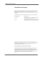
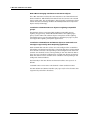
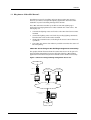
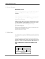
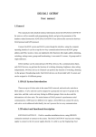
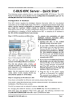
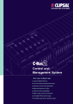
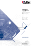
C-Bus OPC installation
C-Bus programming guide
C-Bus OPC installation User Guide
Conventions in this guide
Before you start using this guide, it is important to understand the terms
and typographical conventions used in the documentation. For more
information on specialised terms used in the documentation, consult the
Glossary.
The following kinds of formatting in the text identify special information.
Formatting convention
Type of Information
MENU OPTIONS
Items you must select, such as menu options,
command buttons, or items in a list.
Emphasis
Use to emphasise the importance of a point or
for variable expressions such as parameters.
Copyright 2011 Schneider Electric. All rights reserved. This material is copyright under
Australian and international laws. Except as permitted under the relevant law, no part of this
work may be reproduced by any process without prior written permission of and
acknowledgement to Schneider Electric.
Clipsal and C-Bus are registered trademarks of Schneider Electric.
All other trademarks are the property of their respective owners.
The information in this document is provided in good faith. While Schneider Electric has
endeavoured to ensure the relevance and accuracy of the information, it assumes no
responsibility for any loss incurred as a result of its use. Schneider Electric does not warrant
that the information is fit for any particular purpose, nor does it endorse its use in
applications which are critical to the health or life of any human being. Schneider Electric
reserves the right to update the information at any time without notice.
Sep 2011
ii
© Schneider Electric 2011
Contents
1.0
Overview
1.1
1.2
1.3
1.4
1.5
1.6
1.7
1.8
1.9
2.0
Why have a C-Bus OPC Server? ......................................................................................................................3
For more information.........................................................................................................................................4
Software layers .....................................................................................................................................................4
Host computer system requirements ..........................................................................................................6
C-Bus OPC Server system configurations...................................................................................................7
Modes of operation ............................................................................................................................................7
Licensing .................................................................................................................................................................8
The OPC Data Access interface ...................................................................................................................10
1.8.1
How the OPC Data Access interface works..........................................................................12
OPC Alarms and Events interface...............................................................................................................15
1.9.1
Transmitting Error Reporting into OPC Alarms and Events error data.....................17
1.9.2
Quality of OPC Alarms and Events data and logged data ..............................................23
1.9.3
How the OPC Alarms and Events interface works.............................................................23
Installation
2.1
2.2
2.3
3.0
1
27
Downloading and installing C-Bus Toolkit..............................................................................................27
2.1.1
Installed software ...........................................................................................................................28
Installing the C-Bus OPC Server dongle...................................................................................................28
Downloading and installing C-Bus Toolkit..............................................................................................29
Index
31
© Schneider Electric 2011
iii
1.0 Overview
The C-Bus OPC Server is a stand-alone software package made available
by Clipsal to allow OPC communication between C-Bus networks and
building management systems. The OPC Server acts as a gateway for
transmitting Lighting Compatible and Error Reporting application
information to entities such as building management systems, which are
capable of handling OPC messages.
What is OPC?
The need for system interoperability for the process control,
manufacturing, and building management industry sectors propelled
members of these industries to set up an organisation to develop an open
communication protocol.
The OPC Foundation was created to develop a Microsoft Windows
specification which would make it possible for the development of OPC
servers which can transmit process control data to client software
applications. The specification was later expanded to include
manufacturing and industrial automation.
OPC originally stood for OLE for Process Control, which identified a
Microsoft Windows based specification for system interoperability within
the process control industry.
In building management, OPC interoperability can be utilised to access
data across many lighting networks and building automation systems
over one or more buildings. The diagram below illustrates how OPC
messages travel between applications via an OPC interface and OPC
Servers. Each OPC Server transmits data across a TCP/IP network to
potential building management applications.
Figure 1: OPC Interoperability
© Schneider Electric 2011
1
C-Bus OPC installation User Guide
How C-Bus messaging translates to OPC Server objects
The C-Bus OPC Server utilises the OPC Data Access and OPC Alarms and
Events interfaces, which define how OPC clients and servers can transmit
data to each other. The specification is based around a component object
model and takes advantage of Microsoft DCOM (distributed component
object model) technology.
Translation of OPC Data Access objects to Lighting Compatible
groups
The DA item objects correspond with Lighting Compatible groups:
Lighting, Trigger Group, Enable Network Variable, and Lighting Type
groups such as DALI. The subitem object corresponds to the Lighting
Compatible group. See The OPC Data Access interface (on page 10) for a
list of applicable Lighting Compatible applications.
Translation of OPC Alarms and Events objects to units and error
messages supported by Error Reporting application
Each network that contains at least one unit configured for use with the
OPC Alarms and Events interface has a corresponding area. Each network
area contains unit areas corresponding to the configured units. Each unit
contains unit channel sources corresponding to the unit channels with at
least one error condition configured for use with OPC Alarms and Events.
Each unit channel source contains error conditions corresponding to the
configured alarm conditions.
The hierarchy in the OPC Alarms and Events interface area space is as
follows:
<network name><unit name><unit channel><alarm condition name>
See OPC Alarms and Events interface (on page 15) for a list of C-Bus units
supported by each of the interfaces.
2
© Schneider Electric 2011
Overview
1.1 Why have a C-Bus OPC Server?
An obvious reason for installing and operating a C-Bus OPC Server is
because you want to incorporate lighting application data from C-Bus
networks as part of a building management solution.
The C-Bus OPC Server makes it possible to transmit Lighting Type
application messaging between a C-Bus network and a OPC Client. The
messaging can:
transmit the lighting status and levels to the OPC Client from a C-Bus
network
control the lighting status and levels by sending lighting commands
from the OPC Client to the C-Bus network
show C-Bus network status, indicating if the status is OK or if there is
a problem
The C-Bus OPC Server also makes it possible to monitor the status of
Error Reporting.
C-Bus OPC Server brings C-Bus building management connectivity
The graphic below illustrates how the C-Bus OPC Server can be part of a
larger building management system collecting data for C-Bus lighting
applications and other subsystems networks such as HVAC and security.
Figure 2: OPC Server brings building management data access
C-Bus network
CNI
C-Gate server
HVAC network
Ethernet
OPC Server
for HVAC
Security network
OPC Server
for Security
C-Bus OPC Server
OPC network
Bulding Management system
(OPC Client)
Building Managment
database
© Schneider Electric 2011
3
C-Bus OPC installation User Guide
1.2 For more information
OPC Foundation website
The OPC Foundation http://www.opcfoundation.org/ is tasked to provide
information and support for the development of OPC solutions. Their
website contains links to high level documentation about OPC
technology.
OPC Programmers Connection website
The OPC Programmers Connection http://www.opcconnect.com/ website
provides support for programmers who are developing OPC solutions.
Windows DCOM information
DCOM technology is a Microsoft proprietary technology which is utilised
in the OPC specification. Technical information about DCOM is available
at the Microsoft DCOM developer network
http://msdn2.microsoft.com/en-us/library/ms878122.aspx.
Clipsal technical support
Clipsal technical support for the C-Bus OPC Server is provided via e-mail.
Technical support: Clipsal technical support
mailto:[email protected]
1.3 Software layers
The C-Bus OPC Server is a Microsoft Windows based service which utilises
the DCOM protocol to send/receive OPC commands and messages to the
OPC Client.
List of C-Bus OPC Server software layers and their components
The graphic below illustrates the software layers which support the C-Bus
OPC Server as well as a server containing both the C-Bus OPC Server and
C-Gate.
Figure 3: Software layers for OPC server and for the OPC and C-Gate
server
C-Bus OPC Data Access
Interface
C-Gate
C-Bus OPC
Server
JAVA
C-Bus OPC Error and
Alarm Interface
Commissioning
Application
DCOM
Windows* platform
4
© Schneider Electric 2011
Monitoring
Application
OPC Library
Overview
C-Bus OPC Commissioning Application
The C-Bus OPC Commissioning Application is the programming interface
for C-Bus OPC Server. It establishes OPC Data Access and OPC Alarms and
Events interfaces for linking project network Lighting Compatible and
Error Reporting groups and their levels to OPC groups and items.
C-Bus OPC Monitoring Application
The C-Bus OPC Monitoring Application monitors the health of the C-Bus
OPC Server. Its main functions are to display the status of the C-Bus OPC
Server, configure logging options, view license information, and display CBus OPC Server warnings and errors.
C-Gate server
The C-Gate server contains the C-Bus network details in project format.
The OPC Data Access interface accesses the C-Gate server to transmit
Lighting Compatible data to the OPC Client or to send lighting control
messages to C-Bus networks. The OPC Alarms and Events interface
accesses the C-Gate server to transmit Error Reporting data to the OPC
Client as alarms and events.
C-Bus OPC Server
The C-Bus OPC Server is an OPC Server responsible for translating C-Bus
data into OPC message parameters.
DCOM AND OPC library
DCOM and the OPC library provide support for transmitting OPC
messages across a TCP/IP network.
Microsoft Windows operating system
The OPC software is compatible with a range of Microsoft Microsoft
Windows operating platforms including Microsoft Windows XP, Microsoft
Windows Server 2003, and Microsoft Windows 7 (x86 and x64).
© Schneider Electric 2011
5
C-Bus OPC installation User Guide
1.4 Host computer system requirements
The C-Bus OPC Server has the following host computer system
requirements:
Memory
1024 MB Error correction (ECC) RAM or greater
CPU
Pentium 4 processor, 2.4 GHz or better with 512k on-chip cache. A Core
2 Duo processor E6300 or better is recommended.
Windows operating systems
Microsoft Windows XP Professional, Microsoft Windows Server 2003,
Microsoft Windows 7 (x86 and x64)
Hard drive capacity
80 GB disk with 16 MB on-disk cache, 10000 rpm, server grade, UDMA-6
or SATA-2 is preferred.
LAN connection
Network adaptor 100 Mbps preferred (for access from remote clients or
CNI)
Back up hardware
A battery backed uninterruptible power supply is preferred.
General hardware requirements when installing and integrating to
an OPC Client
For installing and commissioning purposes, the system will require:
6
© Schneider Electric 2011
a PC mouse
Colour display capable of 1024 x 768 resolution or better (for
commissioning)
a single USB port for a license dongle
a port compatible with communications to C-Gate/C-Bus
Overview
1.5 C-Bus OPC Server system configurations
The C-Bus OPC Server can either be installed on its own computer host or
in combination with the C-Gate server (local).
In the combined (local) system configuration, the C-Bus OPC Server and CGate communicate via TCP/IP locally. Communication between the OPC
Client and the C-Bus OPC Server is through the OPC network (TCP/IP). The
diagram below illustrates the network paths by which the C-Bus OPC
Server communicates with C-Gate to transmit Lighting Type messages to
and from the OPC Client.
Figure 4: Stand-alone OPC Server
C-Bus network
OPC Network (TCP/IP)
C-Gate and
C-Bus OPC
Server
OPC Client
In a distributed configuration, C-Gate and the OPC Server exist on
physically separate host computers. C-Gate transmits when requested by
the OPC Server over the TCP/IP network. The C-Bus OPC Server and the
OPC Client are linked by the OPC (TCP/IP ). The graphic below illustrates
the C-Bus OPC Server providing the read/write translation of C-Bus data
between the C-Bus network and the OPC Client.
Figure 5: Distributed configuration
C-Bus network
OPC network (TCP/IP)
C-Gate
C-Bus OPC
Server
OPC Client
1.6 Modes of operation
There are two modes of operation for the C-Bus OPC Server:
commissioning and production. The commissioning mode is used for
when a building site is being commissioned with C-Bus Toolkit. The C-Bus
OPC Server can share the C-Gate server with C-Bus Toolkit. When a
building site has been commissioned, the C-Bus OPC Server operates in
production mode. When C-Bus OPC Server is in production mode, C-Bus
Toolkit should not be used to connect to C-Gate.
In commissioning mode, the C-Bus OPC Server will not open C-Bus
networks or cause C-Gate to synchronise. In production mode, the C-Bus
OPC Server will open any configured C-Bus networks and set the
networks to auto-synchronise.
© Schneider Electric 2011
7
C-Bus OPC installation User Guide
1.7 Licensing
Licensing of the C-Bus OPC Server is divided into three categories:
demonstration, Clipsal C-Bus OPC Server, and CITECT licenses.
Demonstration licensing
If no physical licensing dongle is connected to the USB port of the host
computer, then the C-Bus OPC Server operates in Demo mode. This
means that the C-Bus OPC Server will only run for approximately one hour
and cannot operate in Production mode. The Demo license has no
restrictions on the number of C-Bus networks or OPC items that it can
use.
Clipsal C-Bus OPC Server licenses
The Clipsal C-Bus OPC Server supports the following licenses:
2 network licenses
10 network license
Unlimited network license
C-Bus OPC Server licenses are contained in USB dongles, which can be
purchased from any authorised Clipsal dealer. Each USB dongle works on
a single C-Bus OPC Server installation. The number of C-Bus networks
available in the license must not be exceeded by the number of networks
configured for use with OPC Data Access and/or OPC Alarms and Events
interfaces by the C-Bus OPC Server.
CITECT licenses
The C-Bus OPC Server is able to recognise licenses manufactured by
CITECT. The following CITECT products are supported:
CITECT SCADA
CITECT SCADA Historian
CITECT HMI
CITECT SCADA Facilities
Vijeo Citect
Vijeo Citect Lite
Vijeo Reports
MX4 Historian
Power Logix
Power Logix Lite
Power Logix Historian
Power Logix Facilities
Currently only product versions based on the CITECT SCADA Version 7
platform and later are supported.
8
© Schneider Electric 2011
Overview
Licensing for the C-Bus OPC Server, when activated by a CITECT License, is
based on the number of configured OPC Items. This is referred to as the
point count, and matches the point count of the CITECT license you are
using.
Example: If you have CITECT SCADA with a 500 point count license
installed you can use the C-Bus OPC Server with up to 500 configured
Lighting groups and/or channels of units with at least one alarm or event
configured across any number of C-Bus networks.
When using a dongle with just one of the following CITECT products:
CITECT SCADA Historian
Vijeo Reports
MX4 Historian
Power Logix Historian
the OPC Server operates as an unlimited points count product. If the
dongle is a combination SCADA/Facilities and Historian/Reports dongle,
the points count is limited to the license level of the SCADA/Facilities
points count.
Multiple licenses
If you have a Clipsal license and a CITECT license installed on the same PC
the C-Bus OPC Server will always recognise and use the Clipsal license in
preference to the CITECT license.
For more information about CITECT, see www.citect.com
http://www.citect.com.
© Schneider Electric 2011
9
C-Bus OPC installation User Guide
1.8 The OPC Data Access interface
The OPC Data Access interface supports both Lighting Compatible and
Lighting Type applications, which are used to carry lighting control
messages. Lighting Compatible applications (and related addressing)
include:
Lighting (048-095)
DALI lighting (095)
Ventilation (112)
Irrigation control (113)
Pool, spa, fountain and pond control (114)
HVAC Actuator 1 (115)
HVAC Actuator 2 (116)
Heating (136)
Lighting Based applications have characteristics similar to Lighting and
Lighting Type applications but their overall function is distinct from simply
controlling electrical loads. The two supported Lighting Based
applications and their addresses are:
10
© Schneider Electric 2011
Trigger Control (address: 202)
Enable Control (address: 203).
Overview
The DALI application has been specified for use with the DALI mostly for
the benefit of keeping DALI control separate from other lighting control
operations.
How OPC Data Access handles Lighting Type data
The Lighting Type group transmits integer values within the range of 0255 values. The OPC Data Access handles discrete and ramping
operations differently.
When messages are sent from the C-Bus OPC Server to the OPC
Client
The Lighting Type group levels are transmitted to OPC Client as discrete
values. For example, if the light level changes from 215 to 225, the value
transmitted is 225. When a Lighting Type group ramps the lighting values
over 8 seconds, the OPC server transmits the light levels changing
gradually over the 8 seconds to match the C-Bus ramping.
When messages are sent to the C-Bus OPC Server from the OPC
Client
The OPC Data Access interface translates OPC values in the following way.
If the OPC value is between 0 and 255, this value is converted the same
value in OPC. If the value is over 255, the value in the C-Bus group. If the
value is -2 or less, the value is reset to 0. If the value is -1, the value is set
to 255. This is because in OPC, -1 is equivalent to the local 'true' value,
which is treated as fully On.
There is no provision for sending a ramping command to the C-Bus
network. The best way to ramp lighting levels from an OPC Client is to
activate ramping using C-Bus scenes. In this way, only one control
message is sent via the OPC Data Access interface.
Quality of data and network transmission
The OPC Data Access interface evaluates the quality of information
coming from C-Gate and provides a quality rating on the OPC item values.
The C-Bus OPC Server also monitors the status of all C-Bus networks it is
configured to use, and provides this information through OPC Data
Access
Logging of Lighting Compatible data
The C-Bus OPC Server generates logging data during start/restart and
stopping event sequences as well as operational OPC transmission events.
A subset of the log information is displayed in the MESSAGES tab. The full
log information can be read using the SmartInspect logging viewer. The
location of C-Bus OPC Server log files is at:
C:\Clipsal\CbusOpcServer\Logs, (by default) if the C-Bus OPC
Server is configured to log to files. Logs directly related to OPC Data
Access will contain the words 'OPC DA' in the text.
© Schneider Electric 2011
11
C-Bus OPC installation User Guide
1.8.1
How the OPC Data Access interface works
A simple example of a C-Bus OPC Server implementation is to send
lighting information to and receive lighting control messages from the
OPC Client. Within the C-Bus, there is one network which contains a
Lighting application which controls four dimmer output units, each being
named FLR1_DIM1, FLR1_DIM2, FLR1_DIM3, and FLR1_DIM4.
In the graphic below, the C-Bus network consists of a dimmer and a 4 key
input unit. The C-Bus network is connected to the Ethernet via a CNI unit.
Figure 6: C-Bus connecting to a TCP/IP network
Ethernet (TCP/IP)
C-Bus C-Gate Server
OPC Server
OPC Client
C-Bus network
CNI
Dimmer
4 key input
unit
Transmitting Lighting Compatible lighting data to the OPC Client
The sequence diagram below illustrates the messaging sequencing
between a C-Bus network, a C-Gate server, a C-Bus OPC Server, and the
OPC Client for sending a lighting message originating from a 4 key input
unit.
Figure 7: OPC Lighting message sequence
12
© Schneider Electric 2011
Overview
Messaging sequence
The messaging sequences listed below are part of the process for
translating C-Bus messaging to OPC messaging.
Sequence 1: A building occupant turns Key 1 on which is linked to
DIM1 lighting group.
Sequence 2: A C-Bus FLR1_DIM1 Group ON message is sent across
the C-Bus network. C-Gate is one of the recipients of the ON message
and stores the DIM1 element to 255. At the physical network level,
this turns the dimmer on to full power.
Sequence 3: C-Gate notifies the C-Bus OPC Server that groups have
been set to 255. The link between the FLR1_DIM1 lighting group and
the C-Bus OPC Server allows the translation of the lighting level to an
OPC message. The conversion occurs in the following way:
LIGHTING.FLR1_DIM1 = 255
where OPCITEM refers to the OPC refers to the OPC group, LOCAL
indicates the OPC server identifier, LIGHTING represents an OPC
item, and FLR1_DIM1 represents a LIGHTING subitem.
Sequence 4: OPC message is passed to the OPC Client across the OPC
messaging network. The OPC Client control panel indicates that
FLR1_DIM1 group is ON.
Transmitting control data to the C-Bus dimmer
The sequence diagram below illustrates the messaging sequencing
between a C-Bus network, a C-Gate server, a C-Bus OPC Server, and the
OPC Client for sending an lighting control message from the OPC Client.
Figure 8: OPC Lighting OFF message sequence
Messaging sequence
The messaging sequences listed below are part of the process for
translating OPC messaging to C-Bus messaging.
Sequence 1: The C-Bus OPC Server generates a 0 level for the DIM1
subitem and sends it across the OPC network. The conversion occurs
in the following way:
LIGHTING.FLR1_DIM1 = 0
where OPCITEM refers to the OPC refers to the OPC group, LOCAL
indicates the OPC server identifier, LIGHTING represents an OPC item,
and FLR1_DIM1 represents a LIGHTING subitem.
© Schneider Electric 2011
13
C-Bus OPC installation User Guide
14
© Schneider Electric 2011
Sequence 2: The C-Bus OPC Server receives the OPC message,
translates this to C-Bus 0 lighting level.
Sequence 3: C-Gate server passes the 0 lighting level value to DIM1
lighting group.
Sequence 4. The OFF message is stored in the dimmer unit where it
turns the lighting connected to it OFF.
Overview
1.9 OPC Alarms and Events interface
The OPC Alarms and Events interface provides information about the
status of output unit channels and DALI ballasts. A C-Bus network may
contain Error Reporting compatible units, all of which are reporting the
status of channels or DALI ballasts across the C-Bus.
Error Reporting applications supported
The Error Reporting application is used to report error information
detected or generated by certain C-Bus units over the C-Bus network.
C-Bus units may monitor and detect error conditions, and report those
conditions using the C-Bus error reporting application.
The reports contain information on the source, severity and nature of the
error or fault condition. The status of an error is reported as OK when it is
operating normally.
Devices that receive error reporting messages act upon the information in
whatever manner is appropriate. This may include publishing information
for a user, logging errors or sounding alarms.
C-Bus units which support Error Reporting application
The C-Bus units and Clipsal software which support error reporting are:
DALI gateway ( Unit types: PC_DAL2B, PC_DAL2C)
C-Bus Universal dimmer
3 channel architectural dimmer
6 channel architectural dimmer
12 channel architectural dimmer
3 channel professional dimmer
6 channel professional dimmer
12 channel professional dimmer
The Error Reporting application messaging is processed into error
conditions which are stored as event and alarm states in the C-Bus OPC
Server.
Logging of OPC Alarms and Events data
The C-Bus OPC Server generates logging data during start/restart and
stopping event sequences as well as operational OPC transmission events.
A subset of the log information is displayed in the MESSAGES tab. The full
log information can be read using SmartInspect logging viewer. The
location of C-Bus OPC Server log files is at:
C:\Clipsal\CbusOpcServer\Logs There are log entries with "OPC
AE" in the text for whenever events are sent, alarm conditions are
changed, acknowledgements are received from OPC Clients, and
acknowledgements are sent to C-Bus units.
© Schneider Electric 2011
15
C-Bus OPC installation User Guide
The graphic below shows a C-Bus system containing output units such as
the C-Bus Universal dimmer, the DALI gateway, and the 6 channel
architectural dimmer. All of these output units can generate Error
Reporting messages. The C-Bus OPC Server translates these messages
into OPC alarm or error events. This information is then transmitted
across the OPC network.
Figure 9: BMS Integration
6 Channel Architectural Dimmer (L506D10UA)
Ch 1
Ch 2
Ch 3
Ch 4
4 Channel Universal Dimmer
(L5504D2)
DALI Gateway (5502DAL)
Ch 1 Ch 2
Ch 3 Ch 4
Ch 5
DALI 1DALI 2
Ch 6
Multi sensor
(5753PEIRL)
DLT Key Input
Unit (5085DL)
Ethernet Interface
(5500CN)
Label 1
Label 2
Label 3
Label 4
SCENE
next
1
Ethernet
C-Bus OPC Server
16
© Schneider Electric 2011
3rd Party BMS Client
Server
3rd Party BMS
OPC Server
Overview
1.9.1
Transmitting Error Reporting into OPC Alarms and Events error data
The conversion of Error Reporting messages to OPC Alarms and Events
error conditions involves the C-Bus network, C-Gate, OPC Server, and the
OPC Client as shown in the graphic below. The C-Bus OPC Server passes
Error Reporting messages retrieved from the C-Bus network to the C-Bus
OPC Server. The C-Bus OPC Server houses the OPC Alarms and Events
state machine which manages the error condition states of all Error
Reporting ready C-Bus units.
Figure 10: Component view of the OPC Alarms and Events implementation
C-Bus Network
Error
reporting
application
messages
C-Gate Server
Error reporting
application
message data
extraction
State 1
State 2
OPC Server
State n
State machine
OPC event/
alarm
messages
Alarm
acknowledgements
OPC Client
Error reporting conditions for the output unit
Below is a set of tables containing the OPC error conditions for each unit
type. Each table cross references the OPC error conditions against the
Error Reporting messages stored in C-Gate:
© Schneider Electric 2011
17
C-Bus OPC installation User Guide
OPC mapping to either the Architectural dimmer or Professional
dimmer units
OPC error
condition
Professional dimmer or Architectural
dimmer error conditions
Ballast controller
failure
The Ballast Card Error message indicates
that the ballast card fitted on this channel
has an error.
Channel not
powered
The No Power message indicates that
there is no power in the channel. For
example, the breaker has tripped or that
phase has gone down.
Control
communication
failure
The Control Interface Comm Error message
indicates that the dimming processor has
detected a high number of errors in its
status interface. This is an internal error,
which if it persists, could indicate faulty
hardware.
No hardware
The No Hardware message indicates that
no channel card was detected on this
channel.
Over current
The Over Current message indicates that
the channel has tripped its over current
protection latch and has not succeeded
in restarting.
Over temperature
The Over Temperature message indicates
that the channel has automatically
reduced its operating point due to
overheating. This could be due to
excessive load or inadequate ventilation.
Status
communication
error
The Status Interface Comm. Error message
indicates that a dimming processor has
detected a high number of errors in its
status interface. This is an internal error,
which if it persists could indicate faulty
hardware.
OPC mapping to C-Bus Universal dimmer unit
18
© Schneider Electric 2011
OPC error
condition
C-Bus Universal dimmer error
conditions
Channel not
powered
A No Power On Channel error condition
indicates that there is no power on the
channel. This can be caused by no power
on the card, owing to:
a breaker trip
bypass switch activated
loss of power to the phase supplying
the channel
no load fitted to the channel
Overview
Control
communication
failure
The Communication Error error condition
indicates that an internal
communications error has occurred in
the dimmer.
No hardware
The No Hardware error condition indicates
that there is no card for this channel.
Over current
The Over current error condition indicates
that the channel is over current. This can
be caused by:
Over temperature
Status
communication
error
a short circuit on the channel
tripping the in-built over current
protection.
a significant overload.
The Over Heating error condition indicates
that the channel is overheating. This can
be caused by:
an overloading or poor airflow
no load fitted to the channel
The Unknown Status error condition
indicates that the operational status has
not yet been determined.
OPC mapping to DALI gateway unit
OPC error
condition
DALI gateway error conditions
Ballast failure
The Status error condition indicates
whether the ballast is operating normally
or has detected an internal error.
Ballast not
responding
The Present error condition indicates that
a DALI unit exists on the DALI system
and is responding to status requests. If a
DALI unit is shown as not present, this
may suggest that there is a wiring fault or
problem with the device itself.
Lamp failure
The Load Blown error condition indicates
whether a light has blown.
Lamp power
The On/Off error condition indicates
whether the ballast load is on or off.
No command
received
The Power Failure error condition
indicates if a ballast has had a light level
set since it was powered on.
© Schneider Electric 2011
19
C-Bus OPC installation User Guide
Event and alarm conditions
The OPC Server receives Error Reporting messages from C-Bus, then
processes them as OPC events that may change alarm condition states.
The OPC Server also processes OPC acknowledgment messages from the
OPC Client. The OPC events and alarm conditions are defined below:
Events
An event condition represents a change of state for an error condition of
an output unit channel. For example, an error condition can be the
overheating of an Architectural dimmer channel. If an Architectural
dimmer channel begins to overheat, there is a change of state of the error
condition from inactive to active. If the event is configured to be sent to
OPC Clients, then the C-Bus OPC Server will pass it on with an associated
severity level that ha been configured between 1 (minimum severity) and
1000 (maximum severity).
Alarm conditions
An alarm condition reflects the current stat of an error condition. It also
has an associated severity level that has been configured between 1
(minimum severity) and 1000 (maximum severity), and a possible
requirement for acknowledgement by an OPC Client.
Alarm condition states
If an alarm condition has been configured not to require
acknowledgement, it has two states: inactive and active. When an event is
received from an output unit channel that has a different state, the alarm
condition state will be updated internally and broadcast to the OPC
Clients.
If an error condition has been configured to require acknowledgement, it
has four states:
inactive, acknowledged
active, acknowledged
active, unacknowledged
and inactive, unacknowledged.
Change of states are always associated with a message. The state machine
exists as part of the C-Bus OPC Server. The OPC Server maintains the
status of error conditions by receiving Error Reporting messages from CGate for updating data from the C-Bus units and alarm
acknowledgements from the OPC Client.
When an event is received from an output unit channel that has a
different active state, the alarm condition state will be updated internally
according to a state machine and broadcast to the OPC Clients. If the
acknowledged state is unacknowledged and an OPC Client acknowledges
the alarm condition, the state will be updated internally according to a
state machine and broadcast to the OPC Clients. The state diagram
(below) shows the OPC Alarms and Events states for managing error
conditions.
20
© Schneider Electric 2011
Overview
Figure 11: State diagram showing processing of alarm conditions
Inactive, Acknowledged
[Send "Condition Active'
notification]
[Send "Condition
Inactive"
notification]
[Send "Active
Acknowledged"
notification]
[Send
"Acknowledged"
notification]
Active, Unacknowledged
Active, Acknowledged
[Send
"Acknowledged"
notification]
[Send "Condition Inactive"
notification]
[Send "Condition
Active" notification]
Inactive, Unacknowledged
Quality changed
© Schneider Electric 2011
21
C-Bus OPC installation User Guide
Typical error condition names and their active and inactive states
The table below lists the inactive and active state messages for each of
the error conditions.
List of error conditions and their messages
Error condition
names
Inactive state
messages
Active state
messages
Ballast Failure
Ballast OK
Ballast failure
Lamp Failure
Lamp OK
Lamp failure
Lamp Power
Lamp OFF
Lamp ON
No Command Received Command received
since power on
No command received
since power ON
Ballast Not Responding Ballast responding
Ballast not responding
Channel Not Powered
Channel powered
Channel not powered
Over Temperature
Temperature OK
Over temperature
Over Current
Current OK
Over current
Control Communication Control
Error
communication OK
22
© Schneider Electric 2011
Control
communication error
Status Communication
Error
Status communication Status communication
OK
error
Ballast Controller
Failure
Ballast controller OK
Ballast controller
failure
No Hardware
Hardware present
No hardware
Overview
1.9.2
Quality of OPC Alarms and Events data and logged data
The C-Bus OPC Server provides information on the quality of the
information coming from the OPC Alarms and Events as well as logging
data to track the behaviour of the interface over time.
Quality of OPC Alarms and Events data
The OPC Alarms and Events interface evaluates the quality of information
coming from C-Gate and provides a quality rating.
Logging of OPC Alarms and Events data
The C-Bus OPC Server generates logging data during start/restart and
stopping event sequences as well as operational OPC transmission events.
A subset of the log information is displayed in the MESSAGES tab. The full
log information can be read using SmartInspect logging viewer. The
location of C-Bus OPC Server log files is at:
C:\Clipsal\CbusOpcServer\Logs. There are log entries with "OPC
AE" in the text for whenever events are sent, alarm conditions are
changed, acknowledgements are received from OPC Clients, and
acknowledgements are sent to C-Bus units.
1.9.3
How the OPC Alarms and Events interface works
The sequences below show firstly how alarm conditions are transmitted
and then translated to OPC messages for the 12 channel architectural
dimmer. The second sequence shows how acknowledgements from the
OPC Client are translated from the OPC to Error Reporting messages.
Sending error conditions to the OPC Client
The sequence diagram below illustrates the messaging sequences for
sending an error condition event between a C-Bus network, a C-Gate
server, a C-Bus OPC Server, and the OPC Client.
Figure 12: Sequence showing OPC Client alarm error condition message
Architectural
Dimmer
C-Gate Server
OPC Server
OPC Client
Seq 1
Seq 2
Seq 3
© Schneider Electric 2011
23
C-Bus OPC installation User Guide
The sequence illustrates the messaging sequences that occur to convert a
error condition into an OPC error condition event. The 12 channel
architectural dimmer must be programmed before it is possible to send
error conditions and accept acknowledgements.
Sequence 1: Each channel of the 12 channel architectural dimmer
generates an error condition report at regular intervals or as error
conditions change. The reports are sent as Error Reporting messages
over C-Bus. The message contains information such as the Error
Reporting device ID to uniquely identify the C-Bus unit as well as the
current error condition for the channel.
Sequence 2: The C-Gate notifies the OPC Server of the Error
Reporting error condition. The OPC Server updates the corresponding
alarm condition state according to a state machine and updates any
OPC Clients. converts the Error Reporting messages into error
conditions, then stores the conditions in a state machine. The
conversion occurs in the following way:
FLOOR2.DIMMER.CHANNEL1.OVER_TEMP = TRUE
FLOOR2.DIMMER.CHANNEL1.OVER_TEMP_ACKED = FALSE
where FL00R2 refers to the specific C-Bus network, DIMMER refers
to the unit tag name, CHANNEL1 refers to the first of twelve (12)
channels, and OVER_TEMP refers to an alarm condition state and
OVER_TEMP_ACKED refers to the alarm condition acknowledgement
state (assuming that this alarm condition has been configured to
require acknowledgment).
Sequence 3: As error conditions change, the C-Bus OPC Server sends
OPC events and alarm conditions to the OPC Client.
The sequence diagram below illustrates the messaging sequencing for
receiving an alarm acknowledgement from the OPC Clientbetween a CBus network, a C-Gate server, a C-Bus OPC Server, and the OPC Client.
Figure 13: Sequence showing OPC Client alarm acknowledgment
Architectural
Dimmer
C-Gate Server
OPC Server
OPC Client
Seq 1
Seq 2
Seq 3
The sequence illustrates the messaging sequences that occur to convert
an alarm acknowledgement from an OPC alarm to reset a error condition
state.
Sequence 1: The OPC Client sends an OPC alarm acknowledgement to
the OPC Server. This could be an automated or manual process. The
conversion occurs in the following way:
FLOOR2.DIMMER.CHANNEL1.OVER_TEMP_ACKED = TRUE
24
© Schneider Electric 2011
Overview
where FLOOR2 refers to the specific C-Bus network, DIMMER refers
to the unit tag name, CHANNEL1 refers to the first of twelve (12)
channels, and OVER_TEMP_ACKED refers to the alarm condition
acknowledgement state (assuming that this alarm condition has been
configured to require acknowledgement).
Sequence 2: C-Bus OPC Server sends a message to C-Gate to
acknowledge the alarm condition for this channel.
Sequence 3:C-Gate sends a message to the C-Bus network with the
appropriate Error Reporting device ID set to identify the Architectural
dimmer. The Architectural dimmer updates the acknowledgement
state for the channel and responds with a new error report that
indicates the acknowledgement has been accepted.
© Schneider Electric 2011
25
2.0 Installation
The installation of the C-Bus OPC Server includes the software
components described in the software layers in the Overview chapter. It
also installs software related to the dongle driver and SmartInspect log
viewer.
Before you start
Review the Overview chapter especially the section discussing licensing
You will need access to the Internet to download the C-Bus OPC
Server software.
This installation chapter does not provide information about
installation requirements for third party OPC Clients.
2.1 Downloading and installing C-Bus Toolkit
You can obtain the most recent copy of the C-Bus OPC Server software
package at the Clipsal software download
http://www2.clipsal.com/cis/technical/downloads page.
Download the installation package to a temporary directory.
Double click the installation package to run the installation wizard.
C-Bus OPC Server software package installs to the
C:\Clipsal\CbusOpcServer directory.
© Schneider Electric 2011
27
C-Bus OPC installation User Guide
2.1.1
Installed software
The installed components reside in the C:\Clipsal\CbusOPCServer
directory.
Installed software components
The main components are listed below:
C-Bus OPC Server software components
C-Bus OPC Commissioning Application
C-Bus OPC Monitoring Application
OPC core components
SmartInspect components . The SmartInspect components including
the SmartInspect Console application and and Help file. Both are
installed to C:\Clipsal\CbusOpcServer\SmartInspect.
DCOMPerm application. Command line Helper for setting DCOM
permissions.
Sentinal driver installer for dongle license
C-Bus OPC Server uninstall program
This program removes the C-Bus OPC Server software from the host
computer.
Software applications available in Microsoft Windows Start menu
The following installed applications appear in the Start > Programs >
Clipsal menu :
OPC Server Help file
Commissioning Application
Install-Remove license dongle driver
Monitoring Application
SmartInspect Log Viewer
2.2 Installing the C-Bus OPC Server dongle
Dongles can be purchased from authorised Clipsal or CITECT© dealers.
When you receive the C-Bus OPC Server dongle, remove the cap
protecting the USB connector then insert the dongle into a convenient
USB port. When the dongle is operational, the external tip glows yellow.
The license driver is installed onto the host computer by the C-Bus OPC
Server software package and the license information is made available to
the C-Bus OPC Server.
28
© Schneider Electric 2011
Installation
2.3 Downloading and installing C-Bus Toolkit
You can obtain the most recent copy of C-Bus Toolkit at the Clipsal
software download http://www2.clipsal.com/cis/technical/downloads
page.
1
Download the installation package to a temporary directory.
2
Double click the installation package to run the installation wizard.
3
C-Bus Toolkit installs to the C:\Clipsal directory
© Schneider Electric 2011
29
3.0 Index
C
W
C-Bus OPC Server system configurations • 7
Conventions in this guide • ii
Why have a C-Bus OPC Server? • 3
D
Downloading and installing C-Bus Toolkit •
27, 29
E
Error reporting conditions for the output unit •
17
Event and alarm conditions • 20
F
For more information • 4
H
Host computer system requirements • 6
How the OPC Alarms and Events interface
works • 23
How the OPC Data Access interface works •
12
I
Installation • 27
Installed software • 28
Installing the C-Bus OPC Server dongle • 28
L
Licensing • 8
M
Modes of operation • 7
O
OPC Alarms and Events interface • 2, 15
Overview • 1
Q
Quality of OPC Alarms and Events data and
logged data • 23
S
Software layers • 4
T
The OPC Data Access interface • 2, 10
Transmitting Error Reporting into OPC Alarms
and Events error data • 17
31
© Schneider Electric 2011