1
GigE Vision Area Scan Camera
™
CA-GENM-HUM00
www.imaging.com
Genie HM Series
Camera User’s Manual
Genie Framework 1.70
HM640
HM1024
HM1400
HM1400 XDR
© 2009 DALSA
All information provided in this manual is believed to be accurate and reliable. No responsibility is assumed by
DALSA for its use. DALSA reserves the right to make changes to this information without notice. Reproduction of
this manual in whole or in part, by any means, is prohibited without prior permission having been obtained from
DALSA.
Microsoft and Windows are registered trademarks of Microsoft Corporation in the United States and other
countries. Windows, Windows XP, Windows Vista, Windows 7 are trademarks of Microsoft Corporation.
All other trademarks or intellectual property mentioned herein belong to their respective owners.
Document Date: February 19, 2010
Document Number: CA-GENM-HUM00
*CA-GENM-HUM00*
About DALSA
DALSA is an international high performance semiconductor and electronics company that designs, develops,
manufactures, and markets digital imaging products and solutions, in addition to providing wafer foundry services.
DALSA Digital Imaging offers the widest range of machine vision components in the world. From industry-leading
image sensors through powerful and sophisticated cameras, frame grabbers, vision processors and software to easyto-use vision appliances and custom vision modules.
DALSA is a public company listed on the Toronto Stock Exchange under the symbol “DSA”.
Based in Waterloo, ON, Canada, the company has operations in Montreal, QC; Bromont, QC; Colorado Springs,
CO; Eindhoven, NL; Munich, Germany and Tokyo, Japan.
Contents
GENIE HM SERIES OVERVIEW .............................................................................................................7
DESCRIPTION ............................................................................................................................................7
Genie Application Advantages..........................................................................................................8
PRODUCT PART NUMBERS ........................................................................................................................9
CAMERA PERFORMANCE SPECIFICATIONS ..............................................................................................10
Certifications...................................................................................................................................11
Vibration and Shock Certifications.................................................................................................11
SUPPORTED INDUSTRY STANDARDS ........................................................................................................11
GENIE HM SERIES SENSOR OVERVIEW...................................................................................................12
HM Series Sensor Global Specifications ........................................................................................12
HM Model Specific Specifications ..................................................................................................12
Genie HM Series Responsivity........................................................................................................13
Genie HM Series Effective Quantum Efficiency .............................................................................13
Genie HM Series Sensor Cosmetic Specifications ..........................................................................14
APPLICATION DEVELOPMENT OVERVIEW ...............................................................................................15
Sapera LT Library with optional Processing..................................................................................15
GigE Vision Compliant Environment .............................................................................................15
INSTALLING THE GENIE CAMERA....................................................................................................17
WARNING! (GROUNDING INSTRUCTIONS)...............................................................................................17
GIGE NETWORK ADAPTER GUIDELINE ...................................................................................................17
Supported Network Configurations ................................................................................................17
INSTALLATION OVERVIEW & PREPARATIONS .........................................................................................18
Network and Computer Overview...................................................................................................18
Installation Overview......................................................................................................................19
Preventing Operational Faults due to ESD ....................................................................................19
SAPERA LT LIBRARY INSTALLATION ......................................................................................................20
GENIE CD PACKAGE INSTALLATION .......................................................................................................21
Procedure........................................................................................................................................21
GigE Server Verification.................................................................................................................21
CONNECT THE GENIE CAMERA ...............................................................................................................22
Connectors ......................................................................................................................................22
Status LED Codes ...........................................................................................................................23
Typical LED States on Power Up ........................................................................................................... 23
Genie IP Configuration Sequence ..................................................................................................24
GigE Server Status..........................................................................................................................24
OPTIMIZING THE NETWORK ADAPTER USED WITH GENIE .......................................................................25
Adapter Buffers (receive descriptors) .............................................................................................25
Jumbo Frames.................................................................................................................................25
Interrupt Moderation Rate..............................................................................................................26
Adjust NIC Advanced Configuration Properties..................................................................................... 26
Receive Descriptors Optimization........................................................................................................... 27
Jumbo Frames Optimization ................................................................................................................... 27
Interrupt Moderation Rate Optimization ................................................................................................. 28
Running the Network Configuration Tool.......................................................................................29
UPDATING GENIE FIRMWARE..................................................................................................................30
QUICK TEST WITH CAMEXPERT ..............................................................................................................31
About the User-Defined Camera Name ..........................................................................................32
Genie HM Series-GigE Vision Camera
Contents • 1
SILENT INSTALLATION OF GENIE FRAMEWORK.......................................................................................33
OPERATIONAL REFERENCE................................................................................................................35
CAMERA AND SENSOR INFORMATION .....................................................................................................35
Access Via CamExpert....................................................................................................................35
Power-up Configuration (Saved User Settings)..............................................................................36
Power-up Parameter List ......................................................................................................................... 37
Power-up Control via Sapera LT or GigE Vision Compliant Applications............................................. 37
Camera Information via Sapera LT or GigE Vision Compliant Applications................................38
SENSOR CONTROLS .................................................................................................................................39
Sensor Parameters: Controls Via CamExpert ................................................................................39
Gain and Black Level Controls.......................................................................................................41
Gain and Offset Control via Sapera LT or GigE Vision Compliant Applications..........................41
Partial Scan—Window ROI ............................................................................................................42
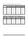
Maximum Frame Rate (fps) Examples (model HM1400/HM1400XDR) ............................................... 42
Maximum Frame Rate (fps) Examples (model HM1024 – 8-bit only) ................................................... 43
Maximum Frame Rate (fps) Examples (model HM640 – 8-bit only) ..................................................... 43
Partial Scan (horizontal cropping)........................................................................................................... 44
Window ROI Control via Sapera LT or GigE Vision Compliant Applications...............................45
CamExpert Image Buffer and ROI Parameters ..............................................................................46
Binning............................................................................................................................................47
Binning Control via Sapera LT or GigE Vision Compliant Applications.......................................48
TRIGGER MODES .....................................................................................................................................48
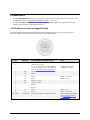
EXPOSURE CONTROLS .............................................................................................................................49
Free-running Programmable Exposure..........................................................................................49
External Trigger Programmable Exposure ....................................................................................50
External Trigger Level-controlled Exposure ..................................................................................51
Exposure Controls via Sapera LT or GigE Vision Compliant Applications...................................52
SYNCHRONIZATION TIMING ....................................................................................................................53
Synchronous Mode..........................................................................................................................53
Reset Mode......................................................................................................................................54
Synchronization Mode via Sapera LT or GigE Vision Compliant Applications.............................54
CAMEXPERT I/O CONTROLS DIALOG .....................................................................................................55
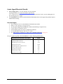
GENERAL INPUTS ....................................................................................................................................56
External Input Signal Opto-coupler & Debounce Circuit ..............................................................56
General Inputs: Settings Via CamExpert........................................................................................56
Input Controls via Sapera LT or GigE Vision Compliant Applications .........................................57
STROBE AND GENERAL OUTPUTS............................................................................................................58
General Outputs: Settings via CamExpert......................................................................................58
Open and Close Output Settings ............................................................................................................. 59
Strobe On Start of Exposure Event Mode ............................................................................................... 59
Pulse On Valid Trigger Event Mode ....................................................................................................... 60
Pulse On Invalid Trigger Event Mode..................................................................................................... 60
Pulse On Start of Readout Event Mode................................................................................................... 61
Pulse On End of Readout Event Mode.................................................................................................... 61
Pulse On End of Acquisition Event Mode............................................................................................... 62
Pulse On Input 1 or Input 2 Event Modes ............................................................................................... 62
Output Control via Sapera LT or GigE Vision Compliant Applications ........................................63
GENIE PROCESSING FEATURES................................................................................................................63
Lookup Table (LUT) .......................................................................................................................63
LUT Control via Sapera LT or GigE Vision Compliant Applications ............................................64
Flat Field (Image Shading) Correction ..........................................................................................65
Important Factors about Flat Field Processing ........................................................................................ 65
Important Factors about the Flat Field Data (TIF) File ........................................................................... 65
Set up Dark and Bright Acquisitions with the Histogram Tool............................................................... 65
Flat Field Correction Calibration Procedure ........................................................................................... 67
Using Flat Field Correction..................................................................................................................... 69
2 • Contents
Genie HM Series-GigE Vision Camera
Flat Field Correction Control via Sapera LT or GigE Vision Compliant Applications.................69
Image Flip.......................................................................................................................................70
Internal Image Test Patterns ..........................................................................................................71
Test Image Select via Sapera LT or GigE Vision Compliant Applications.....................................72
EVENTS ...................................................................................................................................................72
Sapera Callbacks ............................................................................................................................72
Event Selection via GigE Vision Compliant Applications ..............................................................73
NETWORK CONTROLS & GIGE VISION PARAMETERS .............................................................................74
CamExpert GigE Vision Parameters ..............................................................................................74
Network Controls via Sapera LT or GigE Vision Compliant Applications ....................................76
SAPERA SUPPORTED FEATURES LIST ......................................................................................................77
Accessing Features with Sapera++ LT ..........................................................................................77
Feature Type STRING.....................................................................................................................78
Feature Type ENUM.......................................................................................................................78
Feature Type INT32........................................................................................................................80
Feature Type BOOL........................................................................................................................81
Feature Summary List by Function Group .....................................................................................82
Device ..................................................................................................................................................... 82
User Defined Buffers .............................................................................................................................. 82
Sensor...................................................................................................................................................... 82
Sensor Exposure...................................................................................................................................... 83
Acquisition ROI ...................................................................................................................................... 83
Binning Control....................................................................................................................................... 83
LUT Control............................................................................................................................................ 83
Flat Field Control .................................................................................................................................... 83
Trigger Control........................................................................................................................................ 84
I/O Control .............................................................................................................................................. 84
Time Stamp Control ................................................................................................................................ 84
Network Parameters ................................................................................................................................ 85
User Options............................................................................................................................................ 85
Feature Interdependence Diagrams ...............................................................................................86
Trigger Enable - TRUE ........................................................................................................................... 87
Trigger Enable - FALSE ......................................................................................................................... 87
Output Selector........................................................................................................................................ 88
Vertical Binning ...................................................................................................................................... 88
Horizontal Binning.................................................................................................................................. 89
Pixel Format ............................................................................................................................................ 89
Network Configuration Mode ................................................................................................................. 90
Miscellaneous Dependencies ................................................................................................................. 90
Accessing the Genie User Buffer ....................................................................................................91
NETWORK OVERVIEW & TOOLS.......................................................................................................93
USING GENIE WITH ETHERNET SWITCHES ...............................................................................................93
USING GENIE WITH A VLAN ETHERNET SWITCH ...................................................................................93
IP CONFIGURATION MODE DETAILS .......................................................................................................93
Link-Local Address (LLA)...............................................................................................................94
DHCP (Dynamic Host Configuration Protocol).............................................................................95
Persistent IP....................................................................................................................................96
NETWORK CONFIGURATION TOOL ..........................................................................................................97
Quick GigE Vision Camera Network Configuration ......................................................................97
System Information, Configuration, and DHCP Server .................................................................98
System Configuration Parameters ........................................................................................................... 98
System DHCP Server Parameters ........................................................................................................... 99
Network Card Information and Configuration .............................................................................100
NIC IP and DHCP Server Configuration .............................................................................................. 101
Recovering a Camera with an Unknown Persistent IP.................................................................101
Creating a Status Report...............................................................................................................102
Genie HM Series-GigE Vision Camera
Contents • 3
SAPERA GIGE SERVER DETAILS ...........................................................................................................103
SAPERA CAMEXPERT GUIDE ............................................................................................................105
USING CAMEXPERT WITH GENIE HM CAMERAS ..................................................................................105
CamExpert Panes..........................................................................................................................106
CamExpert LUT Controls .............................................................................................................107
TECHNICAL SPECIFICATIONS..........................................................................................................109
MECHANICAL SPECIFICATIONS .............................................................................................................109
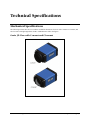
Genie 3D View with C-mount and CS-mount ...............................................................................109
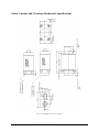
Genie C-mount and CS-mount Mechanical Specifications...........................................................110
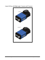
Genie 3D View with Right-angle C-mount and CS-mount............................................................111
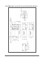
Genie Right-angle C-mount and CS-mount Mechanical Specifications .......................................112
Additional Notes on Genie Mechanical ........................................................................................113
SENSOR ALIGNMENT SPECIFICATION ....................................................................................................113
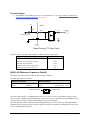
CONNECTORS ........................................................................................................................................114
12-Pin Hirose Connector Signal Details ......................................................................................114
Genie Signal Electrical Details.....................................................................................................115
External Inputs ...................................................................................................................................... 115
External Outputs.................................................................................................................................... 117
RJ45 LAN Ethernet Connector Details .........................................................................................117
CAMERA STATUS LED..........................................................................................................................118
OPTICAL CONSIDERATIONS ...................................................................................................................118
Illumination...................................................................................................................................118
Light Sources ................................................................................................................................118
Filters............................................................................................................................................119
Lens Modeling...............................................................................................................................119
Magnification and Resolution.......................................................................................................119
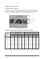
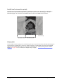
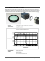
LENS SELECTION OVERVIEW ................................................................................................................120
Lens Mount ...................................................................................................................................120
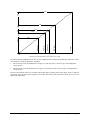
Lens Sensor Size............................................................................................................................120
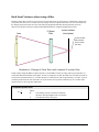
Comparison of a 2/3 Inch and 1 Inch Lens used with a Genie HM 1400 .............................................. 122
Lens Sensor Size vs. Genie HM model ................................................................................................. 122
Additional Lens Parameters (application specific).......................................................................123
SENSOR HANDLING INSTRUCTIONS .......................................................................................................123
Electrostatic Discharge and the Sensor........................................................................................123
Protecting Against Dust, Oil and Scratches .................................................................................124
Cleaning the Sensor Window ........................................................................................................124
Environment..................................................................................................................................124
RUGGEDIZED RJ45 ETHERNET CABLES ................................................................................................125
C/CS-MOUNT NIR AND UV FILTER .....................................................................................................126
Back Focal Variance when using a Filter ....................................................................................127
COMPUTER REQUIREMENTS FOR GENIE CAMERAS................................................................................128
Host PC System.............................................................................................................................128
Ethernet Switch Requirements ......................................................................................................128
IEEE 802.3x Pause Frame Flow Control............................................................................................... 128
Ethernet to Fiber-Optic Interface Requirements ..........................................................................129
EC & FCC DECLARATION OF CONFORMITY .........................................................................................130
TROUBLESHOOTING............................................................................................................................131
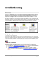
OVERVIEW ............................................................................................................................................131
Problem Type Summary................................................................................................................131
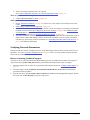
Verifying Network Parameters......................................................................................................133
Before Contacting Technical Support ................................................................................................... 133
INSTALLATION ISSUES AND FUNCTIONAL PROBLEMS............................................................................134
4 • Contents
Genie HM Series-GigE Vision Camera
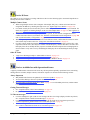
The Windows Firewall Service Can Not Start ..............................................................................134
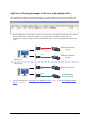
GigE Server Warning Example 1a: IP error with multiple NICs .................................................135
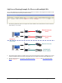
GigE Server Warning Example 1b: IP error with multiple NICs .................................................136
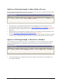
GigE Server Warning Example 2: Subnet Mask or IP error ........................................................137
GigE Server Warning Example 3: Filter Driver Disabled ..........................................................137
GigE Server Warning Example 4: Filter Driver Disabled in Windows XP 64.............................138
DEVICE AVAILABLE WITH OPERATIONAL ISSUES ..................................................................................139
Firmware Updates ........................................................................................................................139
Power Failure During a Firmware Update–Now What? .............................................................140
Cabling and Communication Issues .............................................................................................140
Acquisition Error with a Timeout Message ..................................................................................141
Disabling Windows Firewall................................................................................................................. 141
Acquisition Error without Timeout Messages...............................................................................142
No camera exposure when expected ..................................................................................................... 142
Camera is functional but frame rate is lower than expected.................................................................. 142
Camera acquisition is good but frame rate is lower than expected........................................................ 143
Camera is functional, frame rate is as expected, but image is black ..................................................... 143
Grab has Random Bad Data or Noise ..........................................................................................143
Grab has Random Bad Data or Noise – Case 1 ..................................................................................... 143
Grab has Random Bad Data or Noise – Case 2 ..................................................................................... 144
Grab has Random Bad Data or Noise – Case 3 ..................................................................................... 144
Older Laptop Computer Networking Issues..................................................................................144
Configuration Recommendations with Laptops .................................................................................... 145
Problems with Disconnecting NICs ..............................................................................................145
Ethernet Switch Issues ..................................................................................................................145
Basic Points for all Ethernet Switches................................................................................................... 145
More Complex Configurations.............................................................................................................. 145
Image Loss with Many Cameras Connected to one NIC....................................................................... 145
Other Problems or Issues..............................................................................................................146
Random Invalid Trigger Events ............................................................................................................ 146
Minimum Sapera Version Required ...................................................................................................... 146
Sapera Disconnect-Reconnect Events are Lost ..................................................................................... 146
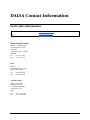
DALSA CONTACT INFORMATION....................................................................................................147
GENIE SALES INFORMATION .................................................................................................................147
GENIE TECHNICAL SUPPORT .................................................................................................................148
GLOSSARY OF TERMS .........................................................................................................................149
INDEX........................................................................................................................................................153
Genie HM Series-GigE Vision Camera
Contents • 5
6 • Contents
Genie HM Series-GigE Vision Camera
Genie HM Series Overview
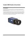
Description
The Genie HM camera family form a series of affordable, easy to use digital cameras specifically engineered for
industrial imaging applications requiring high frame rates. Genie cameras combine standard gigabit Ethernet
technology with the DALSA Trigger-to-Image-Reliability framework to dependably capture and transfer images
from the camera to the host PC.
All Genie cameras are supported by DALSA Sapera™ LT software libraries featuring CamExpert for simplified
camera set-up and configuration. Sapera LT is field proven in thousands of robust industrial applications. Hardware
independent, Sapera LT delivers the same reliable performance regardless of the image acquisition device being
used. This unique feature allows OEM’s to start using the Genie without re-writing applications developed for
DALSA frame grabbers. In addition, Sapera LT includes powerful diagnostics and setup utilities for application
development, custom camera configurations and system deployment.
Genie HM Series-GigE Vision Camera
Genie HM Series Overview • 7
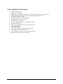
Genie Application Advantages
•
•
•
•
•
•
•
•
•
•
•
•
•
•
•
•
•
Compact, rugged design
GigE Vision 1.0 compliant
Gigabit Ethernet (GigE) interconnection to a computer via standard CAT5e or CAT6 cables
Supports connection to the host computer NIC through a GigE network switch
Available in multiple resolutions
High frame rates relative to similar products
Digital binning for increased sensitivity
Lookup table pre-processing
Real-time shading correction (i.e. Flat Field processing)
Horizontal Flip function
Supports several trigger modes for image capture control
2 opto-isolated inputs
2 opto-isolated outputs
Native Trigger-to-Image Reliability design framework
Visual status LEDs on camera back plate
1µs internal timer or external events can timestamp images
Supported by Sapera™ LT software libraries
8 • Genie HM Series Overview
Genie HM Series-GigE Vision Camera
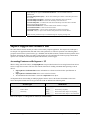
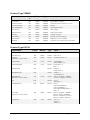
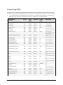
Product Part Numbers
This manual covers the Genie HM models summarized below. See "Camera Performance Specifications" on page
10 for each Genie model.
Camera
fps
Product Number
Resolution
Pixel size
Genie HM640
640 x 480
7.4 x 7.4 µm
301 fps @ 8-bit
CR-GM00-H640x
Genie HM1024
1024 x 768
7.4 x 7.4 µm
136 fps @ 8-bit
CR-GM00-H102x
Genie HM1400
1400 x 1024
7.4 x 7.4 µm
75 fps @ 8-bit
37 fps @ 10-bit
CR-GM00-H140x
1400 x 1024
7.4 x 7.4 µm
75 fps @ 8-bit
37 fps @ 10-bit
CR-GM01-H140x
Genie HM1400 XDR
extended dynamic range
(free running / flat field off)
Lens Mount Option
The last digit of the Genie product number defines the mechanical lens mount.
(see Mechanical Specifications)
C-Mount = 0
CS-Mount = 1
C-Mount downward right angle = 2
CS-Mount downward right angle = 3
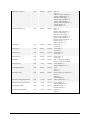
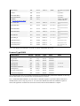
Software
Product Number
Genie Framework composed of the Sapera network Imaging Package, Genie Imaging
Driver and latest Genie Firmware. Required installation.
Included with Genie distribution
CD
Sapera Runtime including CamExpert
Included and installed if desired
GenICam™ support (XML camera description file)
Embedded within Genie
Sapera LT version 6.10 or later (Sapera 7 required for 64-bit support):
OC-SL00-0000000
(sold separately)
Provides everything you will need to develop imaging applications
Sapera documentation in compiled HTML help, and Adobe Acrobat® (PDF) formats.
Sapera Processing Imaging Development Library (sold separately):
Includes over 600 optimized image processing routines.
Contact Sales at
DALSA
Genie Cables & Accessories (sold separately)
Product number
Genie I/O and Power breakout cable (Hirose to Euroconnector)
CR-GENC-IOP00
Tripod mount bracket (mount to Genie top or bottom—provides ¼-20 socket)
CA-GENA-BRA00
Industrial type CAT 6 cable assembly:
Molded shroud with top/bottom thumbscrews on one end with standard Ethernet RJ45
clip on other. Available in various lengths.
See "Ruggedized RJ45 Ethernet Cables" on page 125.
C-mount NIR/UV filter available from Midwest Optical Systems.
See "C/CS-Mount NIR and UV Filter" on page 126.
Genie HM Series-GigE Vision Camera
CA-GENL-BP550
Genie HM Series Overview • 9
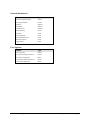
Camera Performance Specifications
Specifications for each available sensor are listed after the general Genie camera specifications.
Camera Controls
Synchronization Modes
Free running
External triggered
Software trigger (through Ethernet)
Exposure Modes
Programmable in increments of 1µs
minimum 10µs in Reset Mode or 56µs in Synchronous Mode
maximum is 4 seconds
Pulse controlled via Trigger pulse width.
Trigger Input
Opto-isolated, 2V to 12V typical, 2mA min.
Debounce range from 1µs up to 255µs
Strobe Output
Output opto-isolated:
Aligned to the start of exposure with a programmable delay, duration and polarity
Features
LUT
8-bit (all models) / 10-bit (only HM1400 and HM1400 XDR)
Flip
Real-time horizontal flip
Binning
Digitally based: Horizontal (2 pixel) and Vertical (2 line)
Timestamp
1µs internal timer or external signal to timestamp images and events
Test image
Internal generator with choice of static and shifting patterns
User settings
Select factory default or one user camera configuration
Optical Interface
Back Focal Distance—C-Mount
17.52 mm
Back Focal Distance—CS-Mount
12.52 mm
Mechanical Interface
Camera Size
29(H) x 44(W) x 67(L) in mm, ( see Mechanical Specifications )
Mass
< 125g (no lens)
Power connector
12 pin male Hirose
Ethernet connector
RJ45
Electrical Interface
Input Voltage
xx-GM0x-xxxxx models +11 to +25.2 Volts DC at 0.6 Amp minimum
(over voltage–reverse voltage protected)
xx-GENx-xxxxx models +11 to +15.2 Volts DC at 0.6 Amp minimum (legacy models)
Power Dissipation
< 4W
Operating Temperature
0 to 45°C (at front plate)
Relative Humidity
5% to 90% non-condensing (operating)
Output Data Configuration
Gigabit Ethernet (IEEE 802.3)
Data and Control
GigE Vision compliant at 1000 or 100 Mbps
10 • Genie HM Series Overview
Genie HM Series-GigE Vision Camera
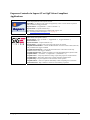
Certifications
CE
EN55022, class A,
EN61000-4-2,
EN61000-4-3,
EN61000-4-4,
EN61000-4-6,
FCC
Part 15, class A
Radio Disturbance Characteristics
Electrostatic discharge immunity test
Radiated, radio-frequency, electromagnetic field immunity test
Electrical fast transient/burst immunity test
Immunity to conducted disturbances, induced by radio-frequency fields
see "EC & FCC Declaration of Conformity" on page 130
RoHS
Compliancy as per European directive 2002/95/EC
(applies to camera part numbers CR-GENx-xxxxx)
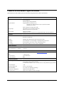
Vibration and Shock Certifications
Test (while operating)
Standard
Description
Sinusoidal vibrations with identification
of critical frequencies
IEC 68-2-6 (1995)
Test Fc
Frequency range: 10 to 2000 Hz
Amplitude: 5 m/s2
Sweep rate: 1 octave per minute
Duration: 1 sweep cycle (to and fro)
Random vibrations
MIL-STD-810E (1989)
method 514.4
Category 10
Levels and frequencies:
0.04 g2/Hz from 20 to 1000 Hz
-6 dB/oct. from 1000 to 2000 Hz
Duration: 1 hour
Shocks
IEC 68-2-27 (1987)
Test Ea and guide
Shape: half-sine
Amplitude: 75 g
Duration: 3 ms
Number: 3 shocks (+) and 3 shocks (-)
Supported Industry Standards
Genie cameras are 100% compliant with the GigE Vision 1.0 specification
which defines the communication interface protocol used by any GigE
Vision device. The device description and capabilities are contained in an
XML file. For more information see:
http://www.machinevisiononline.org/public/articles/index.cfm?cat=167
Genie cameras implement a superset of the GenICam™ specification which
defines device capabilities. This description takes the form of an XML
device description file respecting the syntax defined by the GenApi module
of the GenICam™ specification. For more information see
www.genicam.org.
Genie HM Series-GigE Vision Camera
Genie HM Series Overview • 11
Genie HM Series Sensor Overview
The sensor description below provides a specification table and response graphics. The graph describes the sensor
response to different wavelengths of light (excluding lens and light source characteristics). Visible light spans
wavelengths between about 390 - 780 nanometers. Wavelengths below 390 nm are termed ultra-violet while those
above 780 nm. are termed infra-red. The peak response is around 600 nanometers.
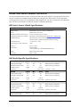
HM Series Sensor Global Specifications
Item / Feature
Specification
Imager Features
Global Shutter, Exposure Control, Anti-Blooming
Sensor
DALSA IA-G5 Area Array
Minimum Frame Rate (free-running)
0.1 fps (one frame every 10 seconds)
Maximum Frame Rate (free-running)
Dependent on Genie HM model (see Partial Scan—Window ROI)
Minimum Exposure
10μs when using reset exposure mode (triggered)
56μs when using synchronous exposure mode (free running)
Maximum Exposure
( 1 / frame rate ) - 10μs
Internal Trigger to Start of Exposure
100μs
Pixel Size
7.4µm x 7.4µm
Pixel Format
8-bit all models
10-bit available only with HM1400/HM1400 XDR
Shutter
Full frame electronic shutter
Gain Range
0dB to +12dB
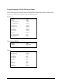
HM Model Specific Specifications
HM1400-XDR
Typical
Min.
Units
Notes
Output Dynamic Range
55.3
53.9
db
With FFC (Factory calibrated)
Maximum Achievable SNR
51.6
51.1
db
With FFC (Factory calibrated)
Full Well Capacity
Responsivity
HM1400
60 000
electron
12
DN/(nJ/cm2)
Typical
Min.
Units
@ 600 nm , 1 x Gain
Notes
Output Dynamic Range
48.2
47.5
db
With FFC (Factory calibrated)
Maximum Achievable SNR
48.3
47.6
db
With FFC (Factory calibrated)
Full Well Capacity
Responsivity
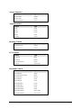
HM1024
24 000
electron
30.6
DN/(nJ/cm2)
Typical
Min.
Units
@ 600 nm, 2.55 x Gain
Notes
Output Dynamic Range
47.5
45.7
db
With FFC (Factory calibrated)
Maximum Achievable SNR
47.1
45.9
db
With FFC (Factory calibrated)
Full Well Capacity
Responsivity
HM640
Output Dynamic Range
24 000
electron
30.6
DN/(nJ/cm2)
Typical
Min.
Units
47.5
45.5
db
12 • Genie HM Series Overview
@ 600 nm, 2.55 x Gain
Notes
With FFC (Factory calibrated)
Genie HM Series-GigE Vision Camera
Maximum Achievable SNR
47.2
Full Well Capacity
45.9
db
24 000
electron
30.6
DN/(nJ/cm2)
Responsivity
With FFC (Factory calibrated)
@ 600 nm, 2.55 x Gain
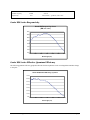
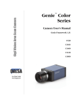
Genie HM Series Responsivity
Genie HM Responsivity Curve
( DN / nJ / cm2 )
14.0
12.0
10.0
8.0
6.0
4.0
2.0
0.0
400
500
600
700
800
900
1000
Wavelength (nm)
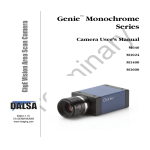
Genie HM Series Effective Quantum Efficiency
The following quantum efficiency graph describes the fraction of photons at each wavelength that contribute charge
to the pixel.
Genie HM Quantum Efficiency (%) Curve
70.0%
60.0%
50.0%
40.0%
30.0%
20.0%
10.0%
0.0%
400
500
600
700
800
900
1000
Wavelength (nm)
Genie HM Series-GigE Vision Camera
Genie HM Series Overview • 13
Genie HM Series Sensor Cosmetic Specifications
The following table lists the current cosmetic specifications for the DALSA sensor used in the Genie HM series.
Blemish Specifications
Maximum Number of Defects
Hot/Dead pixel defects
2
Single pixel defects
100
Clusters defects
0
Column defects
0
Row defects
0
Note: All of the sensor and camera cosmetic specifications are with factory flat-field correction turned on. There are
no pre-flat-field camera cosmetic specifications.
Definition of cosmetic specifications
•
Hot/Dead pixel defect:
Pixel whose signal, in dark, deviates by more than 400DN (10-bits) from the mean.
•
Single pixel defect:
Pixel whose signal, at nominal light (illumination at 50% of the linear range), deviates by more than ±30% from
the mean.
•
Cluster defect:
A grouping of more than 8 pixel defects.
•
Column defect:
A column which has more than 8 consecutive pixel defects.
•
Row defect:
A horizontal grouping of more than 8 consecutive pixel defects.
Test conditions
•
•
•
Digital gain = 1X
Nominal light = illumination at 50% of saturation
Temperature of camera front plate is 40°C
14 • Genie HM Series Overview
Genie HM Series-GigE Vision Camera
Application Development Overview
Sapera LT Library with optional Processing
Sapera LT is a powerful development library for image acquisition and control. Sapera LT provides a single API
across current and future DALSA hardware. Sapera LT delivers a comprehensive feature set including program
portability, versatile camera controls, flexible display functionality and management, plus easy to use application
development wizards.
Sapera Processing is a comprehensive set of C++ classes for image processing and analysis. Sapera Processing
offers highly optimized tools for image processing, blob analysis, search (pattern recognition), OCR and barcode
decoding.
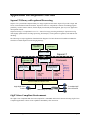
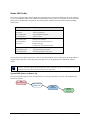
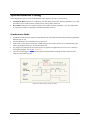
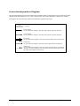
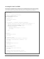
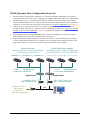
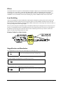
The following is a Sapera application functional block diagram. The Genie Framework installation includes the
Genie driver and the Sapera Network Imaging Package.
User’s Sapera
Application
CamExpert
Sapera LT SDK
Network
Configuration Tool
Genie
Framework
Genie Driver
Images
Control
smart DHCP
Server (optional)
Sapera LT
GigE Server
Sapera Network
Imaging Driver
GVCP
GigE Vision
Control
Protocol
GVSP
GigE Vision
Stream
Protocol
Sapera
Network
Imaging
Package
Ethernet Network Interface Card
single GigE Vision
Camera
Alternatively via a switch
To multiple GigE
Vision Cameras
GigE Vision Compliant Environment
The GigE Vision Compliant XML device description file is embedded within Genie firmware allowing GigE Vision
Compliant applications to know Genie capabilities immediately after connection.
Genie HM Series-GigE Vision Camera
Genie HM Series Overview • 15
16 • Genie HM Series Overview
Genie HM Series-GigE Vision Camera
Installing the Genie Camera
Warning! (Grounding Instructions)
Static electricity can damage electronic components. Please discharge any static electrical charge by touching a
grounded surface, such as the metal computer chassis, before performing any hardware installation.
If you do not feel comfortable performing the installation, please consult a qualified technician.
GigE Network Adapter Guideline
If the computer to be used with the Genie camera does not have a Gigabit network adapter or second built in Gigabit
NIC, a PCI bus Gigabit Network Interface Card (NIC) needs to be installed. Typically under Windows, the PCI
Gigabit NIC is recognized automatically when Windows boots. An example of a high performance NIC is the Intel
PRO/1000 MT adapter.
Review the NIC documentation concerning any special driver required for Windows. Install the PCI bus Gigabit
NIC as described by the NIC manufacture's documentation.
The Genie camera has been tested with a variety of Gigabit network adapters, both built into the system
motherboard and as third party PCI adapters.
Supported Network Configurations
The Genie obtains an IP address using the Link Local Address (LLA) or DHCP, by default. A LLA IP address is
obtained in about 6 seconds with Microsoft Vista or in about 1 minute with Microsoft XP. If required, a persistent
IP address can be assigned (see "Running the Network Configuration Tool" on page 29).
The LLA method automatically assigns the Genie with a randomly chosen address on the 169.254.xxx.xxx subnet.
After an address is chosen, the link-local process sends an ARP query with that IP onto the network to see if it is
already in use. If there is no response, the IP is assigned to the device, otherwise another IP is selected, and the ARP
is repeated. Note that LLA is unable to forward packets across routers.
Alternatively, if a DHCP server is present on the network, the Genie is going to issue a DHCP request asking for an
IP address. The DHCP server will then provide the Genie an IP address. The DALSA Network Configuration tool,
installed with the Genie Framework, can enable the DHCP server (see NIC IP and DHCP Server Configuration).
Genie HM Series-GigE Vision Camera
Installing the Genie Camera • 17
Installation Overview & Preparations
The Genie camera installation generally follows the sequence described below. Detailed installation instructions
follow this overview. This section also provides important information to prevent operational faults due to ESD
(electrostatic discharge) in Genie installations.
Network and Computer Overview
•
Genie needs to connect to a computer with a GigE network adapter, either built in on the computer
motherboard or installed as a third party PCI adapter.
•
Laptop computers with built in GigE network adapters may still not be able to stream full frame rates from
Genie, especially when on battery power. Thorough testing is required with any laptop computer to determine
the maximum frame rate possible (see "Older Laptop Computer Networking Issues" on page 144).
•
Genie also can connect through a Gigabit Ethernet switch. When using VLAN groups, the Genie and
controlling computer must be in the same group (see "Using Genie with a VLAN Ethernet Switch" on page 93).
•
If Genie is to be used in a Sapera development environment, Sapera LT needs to be installed, either before or
after the Genie software package. If Genie will be used in a GigE Vision Compliant environment, Sapera or
Sapera runtime is not required and you need to follow the installation instructions of the third party GigE
Vision compliant package.
•
Install the Genie Framework software package if not using a third party GigE Vision compliant package.
Also install Sapera Run-time with CamExpert to control the Genie.
•
The Windows Firewall exceptions feature is automatically configured to allow the Sapera GigE Server to pass
through the firewall.
•
Computers with VPN software (virtual private network) may need to have the VPN driver disabled in the NIC
properties. This would be required only on the NIC used with the Genie. Testing by the user is required.
18 • Installing the Genie Camera
Genie HM Series-GigE Vision Camera
Installation Overview
•
Before connecting power to the camera, test all power supplies. Power supplies must meet the requirements
defined in section "Genie Signal Electrical Details" on page 115. Apply power to the camera.
•
Connect Genie to the computer GigE network adapter or to the Ethernet switch via a CAT5e or CAT6 Ethernet
cable. Note: cable should not be less than 1 meter (3 feet) long or more than 100 meters (328 feet) long.
•
Check the diagnostic LED which will be initially red then switch to flashing blue while waiting for IP
configuration. See "Status LED Codes" on page 23 for Genie LED display descriptions.
•
Look at the small camera icon added to the Windows tray (next to the clock). Ensure the Genie camera has
been found (right click the icon and select Status).
•
A new Genie installation typically requires a firmware update. See the procedure "Updating Genie Firmware"
on page 30.
•
Use CamExpert (installed either with Sapera or Sapera runtime) to test the installation of the Genie camera. Set
the Genie to internal test pattern. See "Sapera CamExpert Guide" on page 105.
•
Set up the other components of the imaging system such as light sources, camera mounts, optics, encoders,
trigger sources, etc. Test with CamExpert.
Preventing Operational Faults due to ESD
Genie camera installations which do not protect against ESD (electrostatic discharge) may exhibit operational faults.
Problems such as random packet loss, random camera resets, and random loss of Ethernet connections, may all be
solved by proper ESD management.
The Genie camera when used with a simple power supply and Ethernet cable, is not properly connected to earth
ground and therefore is susceptible to ESD caused problems. An Ethernet cable has no ground connection and a
power supply's 0 volt return line is not necessarily connected to earth ground.
DALSA has performed ESD testing on Genie cameras using an 8 kilovolt ESD generator without any indication of
operational faults. The two following methods, either individually or together will prevent ESD problems.
•
Method 1: Use a shielded power supply cable where the shield is connected to earth ground at the supply end
and to the Hirose connector shell at the Genie end. The Genie case is now properly connected to earth ground
and can withstand ESD of 8 kilovolts, as tested by DALSA.
•
Method 2: Mount the Genie camera on a metallic platform which has a good connection to earth ground.
Genie HM Series-GigE Vision Camera
Installing the Genie Camera • 19
Sapera LT Library Installation
Note: to install Sapera LT and the Genie device driver, logon to the workstation as an administrator or with an
account that has administrator privileges.
When Sapera application development is performed on the same computer that the Genie is connected to, the Sapera
Development Library (version 6.20 or later) must be installed. Else, Sapera LT is not required to control the Genie
camera.
•
Insert the DALSA Sapera CD-ROM. If AUTORUN is enabled on your computer, the DALSA installation
menu is presented.
•
If AUTORUN is not enabled, use Windows Explorer and browse to the root directory of the CD-ROM.
Execute launch.exe to start the DALSA installation menu and install the required Sapera components.
•
The installation program will prompt you to reboot the computer.
•
Continue with the Genie CD Package Installation described next.
Refer to Sapera LT User’s Manual concerning application development with Sapera.
20 • Installing the Genie Camera
Genie HM Series-GigE Vision Camera
Genie CD Package Installation
The Genie Framework software package and Sapera runtime provides all components required to control the Genie
with the supplied CamExpert tool. Genie Framework software components include the Network Imaging driver, the
Sapera GigE server, and CamExpert (if Sapera LT library is not installed).
Note: If Sapera application development is required, install Sapera (6.20 or later) as described in the previous
section.
Procedure
•
Insert the DALSA Genie CD-ROM. If AUTORUN is enabled on your computer, the Genie installation menu is
presented.
•
If AUTORUN is not enabled, use Windows Explorer and browse to the root directory of the CD-ROM.
Execute launch.exe to start the installation menu and install the Genie software components.
•
Click to install the Genie Framework Software which includes the Network Imaging driver, and the Sapera
GigE server.
•
The procedure will prompt for acceptance of the installation folder for the Genie files.
•
If desired, click to install Sapera LT run-time which includes CamExpert. Follow the on screen prompts and
reboot when the installation is complete.
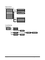
GigE Server Verification
After a successful Genie Framework package installation, the GigE Server icon is visible in the desktop taskbar tray
area. After connecting a camera (see following section), allow a few seconds for the GigE Server status to update.
The Genie camera must be on the same subnet as the NIC to be recognized by the GigE Server.
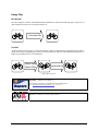
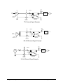
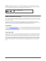
Device Available
Device IP Error
Device Not Available
The normal GigE server tray
icon when the Genie device is
found. It will take a few
seconds for the GigE Server to
refresh its state after the Genie
has obtained an IP address.
The GigE server tray icon
shows a warning when a device
is connected but there is some
type of IP error.
GigE Server
Tray Icon:
A red X will remain over the
GigE server tray icon when the
Genie device is not found. This
indicates a major network
issue. Or in the simplest case,
the Genie is not connected.
If you place your mouse cursor on this icon, the GigE Server will display the number of GigE Vision devices found
by your PC. Right click the icon and select status to view information about those devices. See "Running the
Network Configuration Tool" on page 29 and "Troubleshooting" on page 131for more information.
Genie HM Series-GigE Vision Camera
Installing the Genie Camera • 21
Connect the Genie Camera
Connect a power supply to the Genie camera and an Ethernet cable from the Genie to the host computer. Once
communication with the host computer is started the automatic IP configuration sequence will assign an LLA IP
address as described in section "Genie IP Configuration Sequence" on page 24, or a DHCP IP address if a DHCP
server is present on your network. Note that the DALSA Network Configuration tool can enable the DALSA smart
DHCP server.
The factory defaults for Genie is Persistent IP disabled and DHCP enabled with LLA always enabled as per the
GigE Vision specification. For additional information see "IP Configuration Mode Details" on page 93. See the next
section "Connectors" on page 22 for an overview of the Genie interfaces.
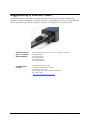
Connectors
The Genie has only two connectors:
•
A single RJ45 Ethernet connector for control and video data transmitted to/from the host computer Gigabit
NIC. See "Ruggedized RJ45 Ethernet Cables" on page 125 for secure cables.
•
A single 12-pin Hirose male connector for camera power plus trigger, strobe and general I/O signals. The
suggested female cable mating connector is Hirose model HR10A-10P-12S.
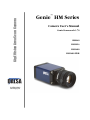
The Genie has one multicolor LED to provide a simple visible indication of camera state (see figure below and
section "Status LED Codes" on page 23). Additionally the RJ45 has two LEDs for network status conditions.
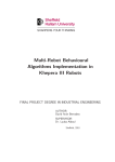
The following figure of the Genie back end shows connector and LED locations. See "Mechanical Specifications"
on page 109 for details on the Genie connectors and camera mounting dimensions.
Genie – Rear View
22 • Installing the Genie Camera
Genie HM Series-GigE Vision Camera
Status LED Codes
The camera is equipped with a LED to display the operational status of the camera. When more than one condition
is active, the LED color indicates the condition with the highest priority (such as an acquisition in progress has more
priority than a valid IP address assignment). The following table summarizes the LED states and corresponding
camera status.
LED State
Definition
LED is off
No power to the camera
Steady Red
Camera not initialized
Slow Flashing Red
Camera initialization problem
Fast Flashing Red
Camera is too hot
Slow Flashing Blue
Waiting for an IP address
Fast Flashing Blue
Ethernet cable disconnected (no link)
Steady Blue
IP address assigned;
no application connected to the camera
Steady Green
Application connected
Slow Flashing Green
Triggered acquisition in progress
Fast Flashing Green
Free-running acquisition in progress
Once the Genie has its RJ45 connected to a network, the Status LED will turn to steady blue when the IP address is
assigned. Only at this time will it be possible by the GigE Server or any application to communicate with the
camera.
Note: Even if the Genie has obtained an IP address, it might be on a different subnet than the NIC it is attached to.
Therefore, if the Genie LED is blue but an application such as CamExpert can not see it, this indicates a network
configuration problem. See the troubleshooting section in this manual.
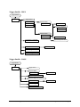
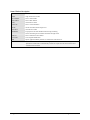
Typical LED States on Power Up
The following LED sequence occurs when the Genie is powered up connected to a network with installed Genie
Framework software.
Red
power connected
Flashing Blue
waiting for IP
Genie HM Series-GigE Vision Camera
Blue
IP assigned
Green
application
connected
Installing the Genie Camera • 23
Genie IP Configuration Sequence
The Genie IP (Internet Protocol) Configuration sequence to assign an IP address is executed automatically on
camera power-up or when connected to a network. As a GigE Vision compliant device, Genie attempts to assign an
IP address as follows.
For any GigE Vision device, the IP configuration protocol sequence is:
• Persistent IP (if enabled)
• DHCP (if a DHCP server is present such as the DALSA Smart DHCP server)
• Link-Local Address (always enabled)
The factory defaults for Genie is Persistent IP disabled and DHCP enabled with LLA always enabled as per the
GigE Vision specification. For additional information see "IP Configuration Mode Details" on page 93.
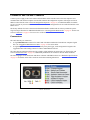
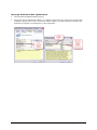
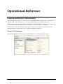
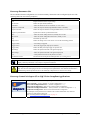
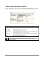
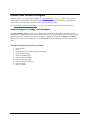
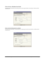
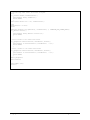
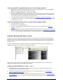
GigE Server Status
Once the Genie is assigned an IP address (its Status LED is steady blue) the GigE server tray icon will not have a
red X through it, indicating that the Genie device was found. It might take a few seconds for the GigE Server to
refresh its state after the Genie has obtained an IP address.
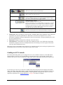
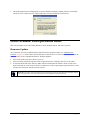
Right-click the GigE Server tray icon to open the following menu.
Click on Show Status to open a window listing all devices connected to the host system. Each GigE device is listed
by name along with important information such as the assigned IP address and device MAC address. The screen
shot below shows a connected Genie with no networking problems.
In the event that the device is physically connected, but the Sapera GigE Server icon is indicating that the connected
device is not recognized, click Scan Network to restart the discovery process. Note that the GigE server
periodically scans the network automatically to refresh its state. See "Troubleshooting" on page 131 for network
problems.
24 • Installing the Genie Camera
Genie HM Series-GigE Vision Camera
Optimizing the Network Adapter used with Genie
Most Gigabit network interface controllers (NIC) allow user modifications to parameters such as Adapter Buffers
and Jumbo Frames. These should be optimized for use with the Genie during the installation.
Adapter Buffers (receive descriptors)
Under certain conditions the host PC system CPU may be very busy with tasks other than the imaging application.
Incoming image packets remain in the PC memory allocated to store packets instead of immediately being copied
into the image buffer. By increasing the NIC host buffers, more incoming image packets can be stored by the NIC
before it must start discarding them. This provides more time for the PC to switch tasks and move image packets to
the image buffer.
Not all network boards allow increasing their buffer count and even among those that do, such as the Intel NIC,
different versions will have different maximum receive descriptor values. Refer to the NIC user documentation for
details on configuring this parameter. The procedure in the following section shows how to increase the number of
packet buffers for one version of Intel network adapter.
Jumbo Frames
With good gigabit Ethernet connections with minimal packet resend conditions, host computer performance can be
further improved by increasing the data packet size. Each streaming video packet causes an interrupt in the host
computer. Therefore increasing the packet size reduces the CPU usage percentage required to handle video data
from Genie.
Important: Before the Genie application can set the Genie feature "Packetsize" to a larger data packet, the NIC used
with the Genie must be configured to allow Jumbo Frames. The procedure in the following section describes
increasing the size of Jumbo Frames for one version of Intel network adapter.
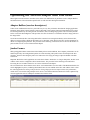
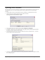
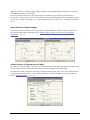
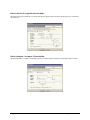
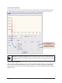
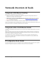
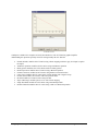
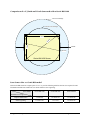
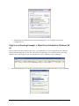
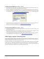
The screenshot below shows that the Genie device was found and there is no IP conflict. The Maximum Packet Size
field is highlighted in yellow, indicating that Jumbo Frames are not enabled on the NIC used with the Genie or that
the control application is forcing a safe packet size. Using a larger packet size improves host CPU performance,
which can be critical when using multiple Genie devices. Note that the Maximum Packet Size field is updated only
when an application such as CamExpert communicates with the Genie.
Genie HM Series-GigE Vision Camera
Installing the Genie Camera • 25
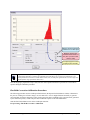
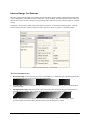
Interrupt Moderation Rate
The Intel Pro/1000 Network adapter provides a configuration parameter to manually adjust the NIC interrupt rate.
By default the NIC driver sets this to 'Adaptive' where the interrupt rate automatically balances packet transmission
interrupts and host CPU performance. In most cases no manual optimization of the Interrupt Moderation Rate
parameter is required.
In some conditions, video frames from the Genie may be transferred to host display or memory buffer as data bursts
instead of a smooth continuous stream. The NIC may be over-moderating acquisition interrupts to avoid overloading the host CPU with interrupts. If priority is required for acquisition transfers (i.e. a more real-time system
response to the Genie transfer), the moderation rate should be reduced by manually adjusting the NIC parameter
(see following section on advanced configuration properties).
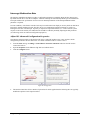
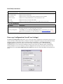
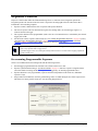
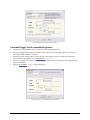
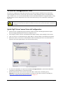
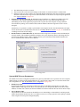
Adjust NIC Advanced Configuration Properties
Note that the following applies to the Intel Pro NIC driver. Other NIC products may or may not have similar
configuration parameters. Screen shots below were made with Intel Pro driver version 8.10.3.0.
•
From the Start menu go to Settings • Control Panel • Network Connections and select the NIC used to
connect the Genie to.
•
Open the Properties for the Ethernet GigE NIC used with the Genie.
•
Click the Configure button.
GigE NIC Configuration
•
The Intel Pro/1000 NIC offers a number of options but for Genie applications the following three are typically
modified to optimize Genie capture transfers.
26 • Installing the Genie Camera
Genie HM Series-GigE Vision Camera
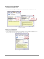
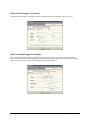
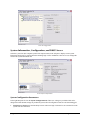
Receive Descriptors Optimization
•
Select the 'Receive Descriptors' property.
•
Change the value to the largest value supported by the installed NIC. In this example the value is 2048.
GigE NIC Receive Buffers
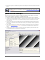
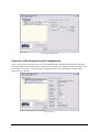
Jumbo Frames Optimization
•
Select the 'Jumbo Frames' property.
•
Change the value to the largest supported by the installed NIC. The Genie can then be configured to use its
maximum Jumbo Frames size. In this example the NIC value is set to 9014.
GigE NIC Jumbo Frames
Genie HM Series-GigE Vision Camera
Installing the Genie Camera • 27
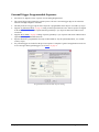
Interrupt Moderation Rate Optimization
•
Select the 'Interrupt Moderation Rate' property.
•
Change the value from the default 'Adaptive'. Try different values from 'Off' to improve the real-time Genie
acquisition response relative to the over-all host computer usability. Note that no interrupt moderation may
make the host computer seem unresponsive to other applications.
28 • Installing the Genie Camera
Genie HM Series-GigE Vision Camera
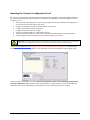
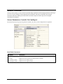
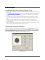
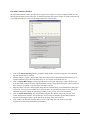
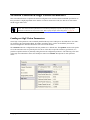
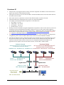
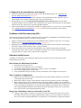
Running the Network Configuration Tool
The Network Configuration tool provides information and parameter adjustments for network adapters installed in
the system and any connected GigE Vision devices without use of any Windows Control Panel application. This
tool allows you to:
• Activate the Network Imaging driver use for image acquisition on any NIC or disable the imaging driver
for any NIC not used with a GigE Vision device.
• Change the Auto Discovery Interval from the default of 15 seconds.
• Configure the Windows firewall exception list.
• Configure the NIC and camera IP settings.
• Assign a User-Defined name to a connected Genie device.
• Assign a Persistent IP address to a Genie device instead of the default DHCP/LLA assigned address.
• Easily Configure the NIC as a DHCP server for connected GigE Vision devices.
Important: Any changes made with this tool will update the Genie flash memory. Do not remove power from the
Genie camera for a minimum 10 seconds. Then cycle the Genie power to load the new flash settings.
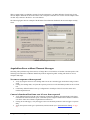
See "Network Configuration Tool" on page 97 for more detailed information on using this tool. As shown below,
the Network Configuration tool can quickly verify and modify the network configuration of the imaging system.
Run the tool from the Windows Start menu: Start•Programs•DALSA Sapera Network Imaging Package•Dalsa
Network Configuration Tool. Verify the Genie camera appears as a child of the NIC card it is connected to. By
default the Genie camera is identified by its serial number if no user-defined name has been assigned.
Genie HM Series-GigE Vision Camera
Installing the Genie Camera • 29
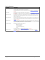
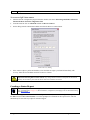
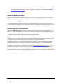
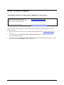
Updating Genie Firmware
The Genie firmware may need to be updated to correspond with the currently installed Genie software framework.
After installing the new Genie software package and Genie camera, update the firmware by following this
procedure.
•
Important: Make sure that no Sapera application (such as CamExpert) is controlling the Genie camera.
•
Start the DALSA Device Manager program from the windows start menu:
Start•Programs•DALSA•Genie•Firmware Update.
•
The right hand column shows whether a firmware update is Required or Not Required.
•
If an update is required, click on the Automatic button. The Update Firmware manager dialog opens and the
new firmware version is written to the Genie camera.
•
The manual button allows the user to select from multiple Genie firmware configuration files – if such files
become available for future operational modes.
•
The firmware update is complete when the lower message output area says "Device reset complete". Close the
Device Manager program.
30 • Installing the Genie Camera
Genie HM Series-GigE Vision Camera
•
Wait for the GigE Server to find the Genie again, then run CamExpert to test the Genie operation (as described
below).
Important: If the Genie power is accidentally cut off during the firmware update (such as a electrical source
power failure or human error), the Genie is easily recovered. See "Power Failure During a Firmware Update–Now
What?" on page 140.
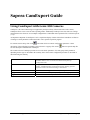
Quick Test with CamExpert
When the Genie camera is directly connected to a Gigabit network adapter on a host computer or via a network
switch, testing the installation with CamExpert is a straightforward procedure.
•
Start Sapera CamExpert by double clicking the desktop icon created during the Genie software installation.
•
CamExpert will search for installed Sapera devices. In the Device list area on the left side, the connected Genie
camera is shown or will be listed in a few seconds after CamExpert completes the automatic device search
(device discovery).
•
Select the Genie camera device by clicking on the camera user-defined name. By default the Genie camera is
identified by its serial number. The Genie status LED will turn green, indicating the CamExpert application is
now connected.
•
Click on the Grab button for live acquisition (the Genie default is Free Running mode). Focus and adjust the
lens iris. See "Operational Reference" on page 35 for information on CamExpert parameters with the Genie
camera.
•
The following figure shows CamExpert with the Genie generating a diagonal test pattern. Select this via the
Test Image Selector drop menu from the Sensor Parameters tab.
Genie HM Series-GigE Vision Camera
Installing the Genie Camera • 31
About the User-Defined Camera Name
The Genie can be programmed with a user-defined name to aid identifying multiple cameras connected to the
network. For instance, on an inspection system with 4 cameras, the first camera might be labeled “top view”, the
second “left view”, the third “right view” and the last one “bottom view”. The factory default user name is set to
match the camera serial number for quick initial identification. Note that the factory programmed Genie serial
number and MAC address are not user changeable.
When using CamExpert, multiple Genie cameras on the network are seen as different "Genie_M640_x" devices.
Click on a Genie device user name to select it for control by CamExpert.
An imaging application uses any one of these attributes to identify a camera: its IP address, MAC address, serial
number or User Name. Some important considerations are listed below.
•
Do not use the camera's IP address as identification (unless it is a persistent IP) since it can change with each
power cycle.
•
A MAC address is unique to a single camera, therefore the control application is limited to the vision system
with that unique camera.
•
The User Name can be freely programmed to clearly represent the camera usage. This scheme is recommended
for an application to identify cameras. In this case, the vision system can be duplicated any number of times
with cameras identified by their function, not their serial numbers or MAC address.
32 • Installing the Genie Camera
Genie HM Series-GigE Vision Camera
Silent Installation of Genie Framework
The Genie Framework installation can be integrated within a developer's installation procedure. The silent
installation mode allows the Genie Framework installation to proceed without the need for mouse clicks from a
user.
Two steps are required:
•
Preparation of a response file to emulate a user.
•
Invoking the Genie Framework installer with command options to use the prepared response file.
Creating the Response File
An installer response file is created by performing a Genie Framework installation with the command line switch
"-r". The response file is automatically named setup.iss which is saved in the \windows folder. One simple
method is to execute the Framework installer from within a batch file. The batch file will have one command line.
As an example, using the executable file name for Framework version 1.40, the command line is:
"Genie_1.40.00.0222 Release.exe" –r
Important: The executable name is enclosed in quotation marks. This is required because of the space characters in
the Genie Framework file name.
Running a Silent Mode Installation
A Genie Framework silent installation, whether done alone or within a larger software installation requires the
Genie Framework executable and the generated response file setup.iss.
Execute the Framework installer with the following command line (using version 1.30 as an example):
"Genie_1.40.00.0222 Release.exe" -s -f1".\setup.iss"
where in this example, the switch –f1".\setup.iss" specifies that the setup.iss file is in the same folder as the
Framework installer.
Genie HM Series-GigE Vision Camera
Installing the Genie Camera • 33
34 • Installing the Genie Camera
Genie HM Series-GigE Vision Camera
Operational Reference
Camera and Sensor Information
Camera and sensor information can be retrieved via a controlling application. Parameters such as camera model,
firmware version, sensor characteristics, etc. are read to uniquely identify the connected Genie device.
All these features, with the exception of the DeviceUserId, are read-only. Sapera LT or GigE Vision Compliant calls
are used to retrieve this information and correctly identify the camera along with its characteristics.
Following is an overview of CamExpert displaying this information followed by tables with the feature name
associated to Sapera LT and to GigE Vision Compliant development environments.
Access Via CamExpert
The Camera Information Parameters tab groups information specific to the individual Genie camera.
Genie HM Series-GigE Vision Camera
Operational Reference • 35
Read Only Parameters
Parameter
Description
Device Vendor Name
For the Genie HM series, this is always DALSA.
Device Model Name
Displays the device model name
Device Version
Displays the device version which includes the firmware release and build.
Firmware Version
Displays the currently loaded firmware version manufacturer's code.
Device ID
Displays the factory set camera serial number.
MAC Address
Displays the unique MAC (Media Access Control) address of the Genie camera.
User Set Parameters
Parameter
Description
Device User ID
Specifies a user written ID, of up to 15 characters, for the Genie camera.
By default, this field is set to the serial number of the camera.
Power-up Configuration
Click Setting to open the Power-up configuration dialog box which allows you to specify
camera power-up configuration. For more information, see "Power-up Configuration" on page
36.
Power-up Configuration (Saved User Settings)
The Power-up configuration dialog allows you to specify the camera configuration to load when powering-up the
camera. The Genie camera flash memory contains two possible configuration settings; the Factory Default (neutral
parameters and in free run mode), and a user-defined Camera Configuration 1. The Camera Power-up
configuration drop-down list box allows you to select either the Factory Default or a user specified camera
configuration file. To save the current CamExpert settings to the camera user-defined (Camera Configuration)
setting, click Save. To view in CamExpert a camera configuration file currently saved in the camera, select the
configuration file in the Load configuration from Camera drop-down list, and click Load. See the parameter list
below.
36 • Operational Reference
Genie HM Series-GigE Vision Camera
Power-up Parameter List
The user-defined Camera Configuration saves in camera memory features that can be configured by the user. The
following table lists most of these parameters.
Parameter
Description
ROI
Region of interest used to crop the image.
Pixel Format
Defines the pixel format (MONO8).
Frame Rate
Defines the frame rate for free run mode. (see note below)
Exposure Control mode
Defines the exposure mode (Programmable or Pulse Controlled)
Exposure duration
Defines the exposure duration for Programmable mode. (see note below)
Exposure synchronization
Synchronous or Reset synchronization mode.
Gain
Defines the sensor analog Gain factor, initially set to 0.0 dB.
Black Level
Defines the sensor analog Black level factor, initially set to 0.
Flip
Horizontal flip: Off or On
Image source
Defines the image source as the sensor or one of the stored image patterns.
Trigger enable
Free-running or triggered.
Trigger source
Selects the trigger input (input pin or software).
Trigger delay
Defines the delay from input trigger to exposure start.
GPI settings
Defines the operational mode of the general input pins.
GPO settings
Defines the operational mode of the general output pins
LUT
Lookup Table function On or Off plus the LUT data.
Flat Field Correction
FFC function On or Off plus the offset/gain data. (see warning below)
Note: Maximum frame rates and exposure durations saved previously with Genie Framework 1.40 may be
slightly reduced by Framework 1.50, to improve acquisition robustness.
Warning: Non-typical or invalid Flat Field data, either from a faulty calibration setup or uploaded by the user,
may cause an error when trying to save the User Settings Power-up Parameters. Such "flawed" Flat field data is
useable during camera operation but can not be sufficiently compressed to be saved as a user setting.
Power-up Control via Sapera LT or GigE Vision Compliant Applications
Genie Sapera parameters for Power-up Configuration:
Sapera
Power-upConfig = {Factory Default = 0, Camera Configuration 1 = 1}
SaveCameraConfigurationSelector = {Camera Configuration 1 = 1}
SaveCameraConfiguration = Write to save selected camera configuration
LoadCameraConfigurationSelector = {Factory Default = 0, Camera Configuration 1 = 1}
LoadCameraConfiguration = Write to load selected camera configuration
In CamExpert, these parameters are available in the “Camera Information” tab, under the
“Power-up Configuration” dialog box.
See "Accessing Features with Sapera++ LT" on page 77.
Genie HM Series-GigE Vision Camera
Operational Reference • 37
XML features for Power-up Configuration:
UserSetSelector = Selects the feature User Set to configure {Factory = 0, UserSet1 = 1}
UserSetLoad = Loads the User Set specified by UserSetSelector to the camera and makes it
active
UserSetSave = Saves the User Set specified by UserSetSelector to the camera
UserSetDefaultSelector = Selects the feature User Set to load at camera reset
Camera Information via Sapera LT or GigE Vision Compliant
Applications
Genie Sapera parameters for Camera and Sensor Information:
Sapera
Interface = {GigE Vision}
DeviceVendorName = “DALSA”
DeviceModelName = “Genie HM1400” for Genie HM1400
DeviceVersion = String representing the version of the camera
FirmwareVersion = String representing the version of the camera firmware
DeviceID = String representing the camera serial number
MACAddress = String representing the camera MAC address
DeviceUserID = String representing the user-define name for the camera
DeviceMaxThroughput = Maximum throughput of image streaming in bytes/sec.
DeviceScanType = {Areascan}
ColorType = Monochrome Sensor
SensorWidth = Width of the sensor in pixels
SensorHeight = Height of the sensor in lines
PixelSize = Number of bits per pixel
In CamExpert, these parameters are visible under “Camera Information” and “Sensor” tabs.
See "Accessing Features with Sapera++ LT" on page 77.
hidden table separator
XML features for Camera and Sensor Information:
DeviceVendorName = Name of camera vendor
DeviceModelName = Name of the camera model
DeviceVersion = Displays the device version which includes the firmware release and build.
DeviceFirmwareVersion = Displays the currently loaded firmware version manufacturer's
code.
DeviceID = Displays the factory set camera serial number.
DeviceUserID = A user set ID of up to 15 characters. By default this field is set to the serial
number of the camera.
DeviceScanType = {Areascan}
DeviceMaxThroughput = Maximum number of bytes per second the device supports
DeviceRegistersStreamingStart = Announces the start of registers streaming without
immediate checking for consistency
DeviceRegistersStreamingEnd = Announces the end of registers streaming and performs
validation for registers consistency before activating them
DeviceRegistersCheck = Performs an explicit register set validation for consistency
DeviceRegistersValid = States if the current register set is valid and consistent
SensorWidth = Width of sensor (effective pixels)
SensorHeight = Height of sensor (effective pixels)
PixelSize = Number of bits per pixel (typically 8 or 10-bits per pixel)
WidthMax = Maximum image width. Depends on binning and ROI settings
HeightMax = Maximum image height. Depends on binning and ROI settings
38 • Operational Reference
Genie HM Series-GigE Vision Camera
Sensor Controls
Genie provides a number of sensor controls to optimize image acquisitions for most imaging solutions. Following is
an overview of the CamExpert controls displaying this information, followed by individual control function
descriptions and tables indicating the feature name associated to Sapera LT and to GigE Vision Compliant
development environments.
Sensor Parameters: Controls Via CamExpert
The Sensor Parameters tab groups the parameters related to the camera sensor configuration for acquisition.
Read Only Parameters
Parameter
Description
Device Scan Type
Displays the device scan type. This is always area scan for Genie.
Color Type
Displays the color type of the sensor (Monochrome for the HM).
Sensor Width (in pixels)
Displays the sensor width (in pixels).
Sensor Height (in pixels)
Displays the sensor height (in pixels).
Genie HM Series-GigE Vision Camera
Operational Reference • 39
User Set Parameters
Parameter
Description
Frame Rate (in Hz)
Specifies the internal trigger frame rate for free run mode, in Hz.
The Sapera SDK specifies the frame rate in milli Hertz.
The maximum frame rate increases by using partial scan (see "Partial Scan—Window ROI" on
page 42).
Gain (in dB)
Specifies the sensor gain in dB. Possible values range from
0 to 12.0 dB, in 0.1 dB increments. For more information, see "Gain and Black Level Controls"
on page 41.
Black level (in DN)
Specifies the sensor black level, in digital number, which is the value assigned to a pixel in a
digital image. Possible values range from 0 to 1023 (1/4 DN for 8-bit mode, 1 DN for 10-bit
mode). See details below.
Binning Horizontal
Enables or disables horizontal binning. Possible values are Disabled or 2 pixels. When set to 2
pixels, the image buffer width parameter is automatically adjusted. For more information, see
"Binning" on page 47.
Binning Vertical
Enables or disables the vertical binning. Possible values are Disabled or 2 lines. When set to 2
lines, the image buffer height parameter is automatically adjusted. Note: for Genie HM binning
is performed digitally therefore there is no increase in frame rate.
Test Image Selector
Specifies the test image. Possible values are:
Off
Grey Horizontal Ramp
Grey Vertical Ramp
Grey Diagonal Ramp Moving
Purity
For more information, see "Internal Image Test Patterns" on page 71.
Exposure Control
Click Setting to open the Exposure Control dialog. For more information, see "Exposure
Controls" on page 49.
40 • Operational Reference
Genie HM Series-GigE Vision Camera
Gain and Black Level Controls
The Genie HM series of cameras provide gain and black level adjustments in the digital domain for the CMOS
sensor. The gain and black level controls can make small compensations to the acquisition in situations where
lighting varies and the lens iris can not be easily adjusted. The user can evaluate Gain and Black Level by using
CamExpert.
Features and limitations are described below.
•
Gain is expressed in decibels (dB). Range from 0dB to +12dB in 0.1dB increments. Gain is a multiplication
factor to the signal. Increasing gain increases the sensor noise proportionately.
Note that a gain of 6dB is a multiplier of 2 (doubles the level).
•
Black level offset is expressed as a digital number ranging from 0 to 1023. As an example, if the Genie HM is
used in 10-bit mode and captures a 1024 step gray level (such as the internal ramp test pattern), an offset of 1
would cause the two lowest gray levels to have a value of 0 (i.e. black level units = 1 DN). Note that in the
same way, the peak white level is one less then maximum and the gain adjustment would be used to then get the
full dynamic range. With the Genie HM in 8-bit mode, the offset values would change by 1 for each data entry
of 4 (i.e. black level units = 1/4 DN).
Important: The Genie gain adjustment range and 0dB point is arbitrarily defined by DALSA for the Genie
camera series. The reference setting of 0dB must not be compared to any other product's gain settings when
evaluating the signal to noise specifications of the two products.
Proper comparisons of two products requires identical illumination with identical camera exposure integration
time, then followed by gain control adjustments to produce an identical image gray level.
Gain and Offset Control via Sapera LT or GigE Vision Compliant
Applications
Genie Sapera parameters for Gain and Black level:
Sapera
Gain = Amplification in dB from 0 to 12.0 dB
BlackLevel = DC offset in DN, range from 0 to 1023
(1/4 DN for 8-bit mode, 1 DN for 10-bit mode)
In CamExpert, these parameters are available under the “Sensor” tab.
See "Accessing Features with Sapera++ LT" on page 77.
XML features for Gain and Black level:
GainRaw = Analog gain in tenth of dB (0.1 dB)
BlackLevelRaw = Black level (offset) in 1/16 of DN
(0 – 4092 with increments of 4 in 10-bit mode and 0 – 1023 with increments of 1 in 8-bit mode)
Genie HM Series-GigE Vision Camera
Operational Reference • 41
Partial Scan—Window ROI
Partial Scan (vertical cropping)
The Partial Scan mode, also know as vertical cropping, reduces the number of video lines grabbed for a frame. By
not scanning the full vertical area of the sensor, the maximum possible acquisition frame rate is proportionately
increased. As an extreme example, the HM640 scanning a 32 line frame (with an appropriately short integration
time), exposed around 1830 fps. A table of frame rates vs. sample vertical cropping values follows.
Scan Start Offset
Partial Image Scan
Scan Line Count
Partial Scan Illustration
Maximum Frame Rate (fps) Examples (model HM1400/HM1400XDR)
Vertical Lines
Acquired
Free Running Acquisition
Triggered Acquisition
(synchronous mode)
(reset mode - minimum 10μs exposure)
Flat Field On
Flat Field Off
Flat Field On
Flat Field Off
8-bit
10-bit
8-bit
10-bit
8-bit
10-bit
8-bit
10-bit
1024
64
32
75
37
64
32
75
37
768
86
43
100
50
86
43
100
50
512
129
64
150
75
129
64
150
75
480
137
68
160
80
137
68
160
80
368
179
89
208
104
179
89
208
104
256
258
129
300
150
258
129
300
150
128
516
258
600
300
498
258
600
300
64
990
516
1200
600
900
516
1200
600
32
1780
1032
2398
1200
1508
1032
1980
1200
16
2962
2020
3952
2398
2279
1677
2824
2277
8
4433
3156
4651
3597
3060
2392
4424
3058
42 • Operational Reference
Genie HM Series-GigE Vision Camera
Maximum Frame Rate (fps) Examples (model HM1024 – 8-bit only)
Vertical Lines
Acquired
Free Running Acquisition
Triggered Acquisition
(synchronous mode)
(reset mode - minimum 10μs exposure)
Flat Field On
Flat Field Off
Flat Field On
Flat Field Off
768
117
136
117
136
512
176
205
176
205
480
188
218
188
218
368
245
285
245
285
256
352
410
352
410
128
705
820
659
820
64
1317
1639
1160
1422
32
2320
2873
1872
2217
16
3745
4524
2702
3086
8
4587
4672
3472
3831
Maximum Frame Rate (fps) Examples (model HM640 – 8-bit only)
Vertical Lines
Acquired
Free Running Acquisition
Triggered Acquisition
(synchronous mode)
(reset mode - minimum 10μs exposure)
Flat Field On
Flat Field Off
Flat Field On
Flat Field Off
480
301
301
293
293
368
391
391
375
375
256
588
588
554
554
128
1054
1054
950
950
64
1926
1926
1605
1605
32
3278
3278
2444
2444
16
4694
4694
3322
3322
8
4694
4694
4032
4032
Genie HM Series-GigE Vision Camera
Operational Reference • 43
Partial Scan (horizontal cropping)
Genie also can crop the acquisition horizontally by grabbing less pixels on each horizontal line. Additionally a
horizontal offset value will start the grab from any pixel count, as shown in the following figure. Note that
horizontal cropping does not increase the maximum frame rate due to the CMOS sensor architecture.
Horizontal Crop
Horizontal Scan offset
Active Horizontal Scan
Window ROI
Vertical and Horizontal Cropping can be combined to grab only a region of interest (ROI). Besides eliminating post
acquisition image cropping done by software in the host computer, a windowed ROI grab reduces the bandwidth
required on the Gigabit Ethernet link since less pixels are transmitted. See "CamExpert Image Buffer and ROI
Parameters" on page 46 to use CamExpert to configure image cropping.
44 • Operational Reference
Genie HM Series-GigE Vision Camera
Window ROI Control via Sapera LT or GigE Vision Compliant
Applications
Genie Sapera parameters for Partial Scan and Window ROI:
Sapera
Width = Buffer width in pixels (must be an even value)
Height = Buffer height in lines
OffsetX = Horizontal Offset of the leftmost pixel relative to the sensor (must be an even value)
OffsetY = Vertical offset in lines of the uppermost pixel relative to the sensor
PixelFormat = {Monochrome 8-bit (all models),
Monochrome 10-bit (available with HM1400 and HM1400 XDR)}
See "Accessing Features with Sapera++ LT" on page 77.
XML features for Partial Scan and Window ROI:
Width = Width of image region of interest (must be an even value)
Height = Height of image region of interest
OffsetX = Left coordinate of region of interest (must be an even value)
OffsetY = Top coordinate of region of interest
LinePitch = Distance between consecutive lines in bytes
PixelColorFilter = Color filter convention of the image ((None, BayerRG, BayerGB, BayerGR
or BayerBG)
PixelFormat = Format of the image pixels as per SNFC specification
PixelCoding = Feature indicates the coding of the image pixels. Raw data is the native format of
the sensor.
PixelDynamicRangeMin = Minimum pixel value sent by camera
PixelDynamicRangeMax = Maximum pixel value sent by camera
Genie HM Series-GigE Vision Camera
Operational Reference • 45
CamExpert Image Buffer and ROI Parameters
CamExpert provides controls to configure acquisitions via the Image Buffer and ROI Parameters tab. The image
buffer can be easily cropped as desired. Below is the CamExpert dialog and parameter descriptions follow.
Parameter
Description
Pixel Format
For the Genie HM series, the image buffer format is Monochrome 8-bit or 10-bit, dependent on
model.
Width (in Pixels)
Displays the image buffer width (X axis), in pixels.
Height (in Pixels)
Displays the image buffer height (Y axis), in pixels.
OffsetX (in Pixels)
Specifies the offset in X, from the left of the image, when using an ROI. The image buffer
width is automatically adjusted to compensate for this offset.
OffsetY (in Lines)
Specifies the offset in Y, from the top of the image, when using an ROI. The image buffer
height is automatically adjusted to compensate for this offset.
Image Flip
Enables hardware based horizontal image flip.
Note: When operating in binning mode, the resolution is halved and the coordinate system is scaled accordingly.
For instance, an OffsetX of 20 pixels at nominal resolution is equivalent to an OffsetX of 10 pixels with
horizontal binning enabled.
46 • Operational Reference
Genie HM Series-GigE Vision Camera
Binning
Binning is the process where the charge on two (or more) adjacent pixels is combined. This results in increased light
sensitivity since there is twice the sensor area to capture photons. The sensor spatial resolution is reduced but the
improved low-light sensitivity plus lower signal-noise ratio may solve a difficult imaging situation. The user can
evaluate binning by using CamExpert.
Genie supports horizontal and vertical binning independently, by a factor of 2 in each axis. Specifically if horizontal
binning only is activated, a nominal 640x480 image is reduced to 320x480. If vertical binning only is activated, the
image is reduced to 640x240. With both binning modes activated, the resulting image is 320x240.
With the Genie HM, binning is performed digitally, therefore there is no increase in acquisition frame rate. The
following graphic illustrates binning.
1
Horizontal Binning
3
1
Line
1
Line
2
Line
3
Line
4
Vertical Binning
2
Line
479
Line
480
4
2
639
640
Repeated for each
line of pixels
320
Line
1
Repeated for each column of pixels
Line
2
Line
240
Horizontal and Vertical Binning Illustration
Genie HM Series-GigE Vision Camera
Operational Reference • 47
Binning Control via Sapera LT or GigE Vision Compliant Applications
Genie Sapera parameters for Binning:
Sapera
BinningHorizontal = {Disabled = 1, 2 pixels = 2}
BinningVertical = {Disabled = 1, 2 lines = 2}
In CamExpert, these parameters are available under the “Sensor” tab.
See "Accessing Features with Sapera++ LT" on page 77.
XML features for Binning:
BinningHorizontal = Number of horizontally binned pixels (1=no binning, 2=binning of 2)
BinningVertical = Number of vertically binned lines (1=no binning, 2=binning of 2 lines)
Trigger Modes
Genie image exposures are initiated by an event. The trigger event is either the camera's programmable internal
clock used in free running mode, an external input used for synchronizing exposures to external triggers, or a
programmed function call message by the controlling computer. These triggering modes are described below.
•
Free running (trigger disabled): The Genie free-running mode has a programmable internal timer for frame
rate and a programmable exposure period. Frame rate is 0.1 fps to the maximum supported by the sensor.
Exposures range from 56µs to a maximum also dependent on the current frame rate. This always uses
Synchronous mode where exposure is aligned to the sensor horizontal line timing.
•
External trigger: Exposures are controlled by an external trigger signal. External signals are isolated by an
opto-coupler input with a time programmable debounce circuit. See "General Inputs" on page 56. The
following section provides information on external trigger timing.
•
Software trigger: An exposure trigger is sent as a control command via the Ethernet network connection.
Software triggers can not be considered time accurate due to network latency and sequential command jitter.
But a software trigger is more responsive than calling a single-frame acquisition (Snap command) since the
latter must validate the acquisition parameters and modify on-board buffer allocation if the buffer size has
changed since the last acquisition.
48 • Operational Reference
Genie HM Series-GigE Vision Camera
Exposure Controls
Exposure Control modes define the method and timing of how to control the sensor integration period. The
integration period is the amount of time the sensor is exposed to incoming light before the video frame data is
transmitted to the controlling computer.
•
Exposure control is defined as the start of exposure and exposure duration.
•
The start of exposure can be an internal timer signal (free-running mode), an external trigger signal, or a
software function call trigger.
•
The exposure duration can be programmable (such as the case of an internal timer) or controlled by the external
trigger pulse width.
•
For the Genie camera, exposure control modes are "Free-running Programmable Exposure" on page 49 (timer),
"External Trigger Programmable Exposure" on page 50 (timer) and "External Trigger Level-controlled
Exposure" on page 51 (trigger pulse width). Following are details for each mode.
Note: Do not change the exposure time while grabbing, else an Invalid Trigger Event may be generated. This
applies to any exposure mode or trigger source.
The Invalid Trigger Event is not catastrophic and only indicates the loss of a video frame. Stopping acquisitions
first will avoid this error.
Free-running Programmable Exposure
Genie is in a multifunctional free running mode with the following features:
•
Internal trigger programmable from maximum sensor frame rate down to 0.1Hz.
•
Exposure synchronization timing is "Synchronous Mode" on page 53 where the exposure is aligned with the
sensor horizontal line timing and the next acquisition is triggered by an internal programmable timer.
•
Exposure duration is user programmable (exposure maximum is dependent on the frame rate). Minimum
exposure is 56µs.
•
Image readout is simultaneous where the grabbed image frame is readout during the next frame exposure time.
This allows for fastest possible frame rates. See the timing diagram below.
Free-running Programmable Exposure Timing
Genie HM Series-GigE Vision Camera
Operational Reference • 49
External Trigger Programmable Exposure
•
Also known as “Edge Pre-select” exposure. See the timing diagram below.
•
The external trigger edge initiates the exposure process. The active external trigger edge can be selected as
either the low-high or high-low transition.
•
The delay from active trigger edge to start of exposure is programmable from 100μs to 4 seconds (1μs steps) .
•
Supports "Synchronous Mode" on page 53 timing for fastest possible frame rates. Start of exposure is aligned
on the next horizontal line while exposure duration granularity is 1µs. Exposure and sensor readout can be
concurrent.
•
Supports "Reset Mode" on page 54 timing. Exposure granularity is 1µs. Exposure and sensor readout must be
sequential, limiting the maximal frame rate.
•
Exposure duration is programmable from 10μs in Reset Mode or 56µs in Synchronous Mode, to 4 seconds
(with 1μs steps).
•
Any external trigger received before the previous exposure is complete is ignored. An application can elect to
receive messages about ignored triggers. See "Events" on page 72.
Programmable Synchronous Mode Exposure Timing
50 • Operational Reference
Genie HM Series-GigE Vision Camera
Programmable Reset Mode Exposure Timing
External Trigger Level-controlled Exposure
•
Also known as “Pulse Width Control” exposure. See the timing diagram below.
•
The external trigger edge initiates the exposure process. The active external trigger edge can be selected as
either the low-high or high-low transition.
•
No delay from active trigger edge to start of exposure. Note that the user must account for the input optocoupler electrical specifications (see "External Inputs" on page 115).
•
Exposure is stopped by the opposite edge on the trigger signal. Therefore the exposure time is defined by the
trigger pulse duration.
•
Supports "Reset Mode" on page 54 trigger timing only.
External Trigger Level-controlled Exposure Timing
Genie HM Series-GigE Vision Camera
Operational Reference • 51
Exposure Controls via Sapera LT or GigE Vision Compliant
Applications
Genie Sapera parameters for Exposure Control:
Sapera
FrameRate = 0.1 Hz up to max. frame rate supported by sensor in current mode of operation.
Only available with Trigger disabled.
ExposureMode = {Programmable = 1, Pulse Controlled = 2}
ExposureTime = Exposure duration in µs
In CamExpert, these parameters are available under “Sensor” tab.
See "Accessing Features with Sapera++ LT" on page 77.
XML features for Exposure Control:
ExposureMode = {Off = 0, Timed = 1, TriggerWidth = 2, TriggerControlled = 3,
ResetContinuous = 4}
ExposureTimeRaw = Exposure duration in µs
ExposureDelay = The delay from active trigger edge to start of exposure.
AcquisitionFrameRateRaw = Controls the desired frame rate of the camera in mHz (0.001 Hz).
Only available when trigger is disabled.
AcquisitionFrameRateAbs = Controls the desired frame rate of the camera in Hz. Only
available when the frame trigger is disabled.
AcquisitionFrameCount = Number of frames to be acquired in MultiFrame acquisition mode
AcquisitionMode = {Continuous = 0, SingleFrame = 1, MultiFrame = 2}
AcquisitionArm = Verify all parameters for image capture and prepares for AcquistionStart
AcquisitionStart = Start image capture using currently selected acquisition mode
AcquisitionStop = Stop the acquisition at the end of the current exposure
AcquisitionAbort = Abort an acquisition immediately without completing the current frame
TLParamsLocked = Flag to indicate if features are locked during acquisition.
52 • Operational Reference
Genie HM Series-GigE Vision Camera
Synchronization Timing
Genie supports two types of sensor synchronization used to align the exposure to sensor timing:
•
Synchronous Mode: Exposure is synchronous to the line timing of the sensor. Exposure granularity is 1µs and
the readout can be concurrent to the exposure for the fastest possible frame rate.
•
Reset Mode: Timing is reset to initiate exposure of next frame. Exposure granularity is 1µs, but readout must
be sequential to exposure, reducing the maximum achievable frame rate.
Synchronous Mode
•
Synchronous mode starts the exposure period aligned to the sensor horizontal line timing and the programmable
duration steps are 1µs.
•
Exposure duration is from a minimum of 56µs up to 4 sec.
•
In this mode, sensor exposure and sensor readout of the previous frame's exposure occur simultaneously. This
allows operating the sensor up to its maximum frame rate.
•
Any trigger received before the end of the exposure is ignored. The application can elect to receive messages
about ignored triggers. See "Events" on page 72.
•
Since the external trigger is asynchronous with the Genie horizontal line timing, the frame exposure start is
subject to 1 horizontal line jitter.
Synchronous Mode Timing example for Genie
Genie HM Series-GigE Vision Camera
Operational Reference • 53
Reset Mode
•
Exposure starts immediately after a valid trigger. There is no jitter on the start of exposure.
•
Exposure time is programmable or controlled by the trigger pulse width.
•
Minimum exposure is 10µs – maximum is 4 seconds, with steps of 1µs.
•
Sensor readout must complete before the next exposure can start. That is, exposure and readout are sequential.
Therefore, the maximum frame rate is lower than for Synchronous mode.
•
Any external trigger received before the previous exposure/read out sequence is complete is ignored. An
application can elect to receive messages about ignored triggers. See "Events" on page 72.
Reset Mode Timing example for Genie
Synchronization Mode via Sapera LT or GigE Vision Compliant
Applications
Genie Sapera parameters for Synchronization Mode:
ExposureAlignment = {Synchronous = 0, Reset = 1}
Sapera
In CamExpert, these parameters are available under the “Sensor” tab in the “Exposure Control”
dialog box.
See "Accessing Features with Sapera++ LT" on page 77.
XML features for Synchronization Mode:
ExposureAlignment = {Synchronous = 0, Reset = 1}
54 • Operational Reference
Genie HM Series-GigE Vision Camera
CamExpert I/O Controls Dialog
CamExpert groups the Genie I/O Controls Parameters in one group. These parameters allow configuring the Genie
inputs and outputs for type of signal and signal polarity. The screen capture below shows the CamExpert I/O
parameters dialog and is followed by a descriptive overview. Detailed information on inputs and outputs follow this
section.
I/O Controls Dialog
Parameter
Description
Trigger
Enables or disables the Genie camera trigger.
Trigger Source
Specifies the trigger source. Possible values are Software, Input 1, or Input 2.
Note that this field is only available when the Trigger parameter is True.
Frames per Trigger
Set the number of frames acquired per trigger – max. 64k
Timestamp Counter
Select Timestamp increment source ( Internal 1µs Clock, Input 1, Input 2, End of Readout )
Timestamp Reset Source
Select event source for Timestamp Reset ( Off, Input 1, Input 2 ).
Important; The timestamp reset function is described below, using Input 1 as the selected
example (applies to Input 2 also). For correct timestamp counter operation, do not use the same
"external signal input" for both the reset and counter source.
Case 1
Input 1 polarity setting = Active High
Input 1 signal = High
Timestamp function is enabled
Case 2
Input 1 polarity setting = Active High
Input 1 signal = Low
Timestamp is held in Reset –
counter is always 0
Case 3
Input 1 polarity setting = Active Low
Input 1 signal = Low
Timestamp function is enabled
Case 4
Input 1 polarity setting = Active Low
Input 1 signal = High
Timestamp is held in Reset –
counter is always 0
Timestamp Reset
Software Reset: Reset the Timestamp counter immediately (click mouse in command field).
Input Settings
Click on Setting to open the Input Settings dialog box, which allows you to specify the trigger
input settings. For more information, see "General Inputs: Settings Via CamExpert" on page 56.
Output Settings
Click on Setting to open the Output Settings dialog box, which allows you to specify the
trigger output settings. For more information, see "General Outputs: Settings via CamExpert"
on page 58.
For more information on triggers, see "General Inputs" on page 56.
Genie HM Series-GigE Vision Camera
Operational Reference • 55
General Inputs
External Input Signal Opto-coupler & Debounce Circuit
•
Genie provides two sets of opto-coupled inputs for either RS422 or TTL signals. These can be used as external
trigger sources.
•
See "12-Pin Hirose Connector Signal Details" on page 114 for connector pinout and electrical information. The
cable shell and shield should electrically connect the Genie chassis to computer chassis for maximum EMI
protection.
•
For external triggers, a rising edge signal is suggested to minimize the time it takes for the opto-coupler to
change state. (The opto-coupler response time is typically 10µs for rising edge compared to 50μs for falling
edge).
•
Each input incorporates a signal debounce circuit (following the opto-couple) to eliminate short noise
transitions that could be wrongly interpreted as a valid pulse. The duration is user-programmable from 1µs to
255µs with CamExpert.
•
Note, the external trigger input propagation delay is dependent on the signal used to activate the opto-coupled
input. Typical delays are 3 µs for Active Open and 5 µs for Active Close.
General Inputs: Settings Via CamExpert
CamExpert provides control of inputs via the I/O Controls Parameters tab. The Input Settings dialog box allows
you to view the signal and status for each pin on the Hirose connector. The Polarity drop-down list boxes, located
in the INPUT Settings area, allow you to specify the polarity of the Input 1 and Input 2 as either Active High or
Active Low. The Minimum duration field for each input, allows you to specify the minimum trigger length (1255µs ) so that input transitions are debounced to prevent unwanted trigger events.
Input Settings Dialog
56 • Operational Reference
Genie HM Series-GigE Vision Camera
Input Controls via Sapera LT or GigE Vision Compliant Applications
Genie Sapera parameters for Trigger Modes, Time Stamp and General Inputs:
Sapera
TriggerDelayToIntegration = Delay in µs from trigger to exposure
TriggerEnable = {FALSE, TRUE}
TriggerSource = {Input 1 = 0, Input 2 = 1, Software = 2}
TriggerSoftware = {FALSE, TRUE}
FramesPerTrigger = Frame count 1 to 32767
TimestampResetSource = {Off = 0, Input 1 = 1, Input 2 = 2}
TimestampCounter = {Internal Clock = 0, Input 1 = 1, Input 2 = 2, End of Readout = 3}
TimestampReset = {FALSE, TRUE}
PolarityInput_x = {Active High = 0, Active Low = 1}
DebounceInput_x = debouncing period in µs (from 1 to 255 µs)
InputPinStatusInput_1 = {FALSE, TRUE}
InputPinStatusInput_2 = {FALSE, TRUE}
See "Accessing Features with Sapera++ LT" on page 77.
XML features for Trigger Modes, Time Stamp and General Inputs:
TriggerMode = {Off = 0, On = 1}
TriggerSelector = Select the type of trigger to control. FrameStart currently supported.
TriggerSoftware = Generates a software trigger to start the acquisition in any trigger mode
TriggerSource = External input or software signal as trigger source {Line2 = 1, Software = 2}
TriggerActivation = {LevelLow = 0, LevelHigh = 1, RisingEdge, FallingEdge, AnyEdge}
TriggerDelayAbs = Absolute delay to apply in us after reception of the trigger signal before
starting exposure
TriggerDelayRaw = Absolute delay to apply in us after reception of the trigger signal before
starting exposure
GevTimestampTickFrequency = 64-bit value indicating the number of timestamp clock ticks
in one second.
GevTimestampControlLatch = Latches the current timestamp value of the device.
GevTimestampControlReset = Resets the timestamp count of the device.
GevTimestampValue = Latched 64-bit value of the timestamp. Value must first be latched
using GevTimestampControlLatch.
CounterSelector = Select counter to configure. Currently only Timestamp is supported.
CounterEventSource = Select counter source as {Internal Clock = 0, Input 1 = 1, Input 2 = 2,
End of Readout = 3}
CounterLineSource = Source for the line to count.
CounterReset = Resets the selected Counter.
InputLineSelector = Index to general input {input1=0, input2=1}
InputLinePolarity = {Active High = 0, Active Low = 1}
InputLineDebouncingPeriod = debounce period in µs (from 1 to 255 µs)
InputLineValue = Read input line state {low=0, high=1}
LineStatus = Current logical state of signal at time of polling {FALSE, TRUE}
Line Mode = Indicate if the line is an input or an output.
Genie HM Series-GigE Vision Camera
Operational Reference • 57
Strobe and General Outputs
Genie provides two sets of opto-coupled outputs (see "External Outputs" on page 117). These can be used as a
strobe signal to control lighting or to generate programmable pulses when specific events are generated by the
camera. They can also be set to a static state (close or open) by the application.
See "12-Pin Hirose Connector Signal Details" on page 114 for connector pinout and electrical information.
General Outputs: Settings via CamExpert
The Output Settings dialog box allows you to configure the event mode for both output 1 and output 2. Each
output can be set independently to one of the available event modes. A typical usage of output is to control a strobe
light in relation to the camera exposure. Select the output to configure by clicking on the Output 1 or Output 2
buttons located at the top of the dialog box. Use the Event mode drop-down list box to select the required event
mode.
The following output signal events are available:
•
•
•
•
•
•
•
•
•
•
Open (default)
Close
Strobe On: Start of Exposure (used for strobe pulse)
Pulse On: Valid Trigger
Pulse On: Invalid Trigger
Pulse On: Start of Readout
Pulse On: End of Readout
Pulse On: End of Acquisition
Pulse On: Input 1
Pulse On: Input 2
58 • Operational Reference
Genie HM Series-GigE Vision Camera
When an event mode is selected, its trigger output schematic or signal timing diagram is displayed, as well as any
other additional parameters for the mode.
For most event modes, the trigger output signal can be set to either Active Open (that is high with the load
connected to a voltage source) or Active Closed (where current is drawn through the load). The output delay can be
set from 0 to 4 seconds, in increments of 1 µs. The pulse duration can be set from 10µs to 4 seconds, in increments
of 1 µs.
Open and Close Output Settings
You can open and close the output circuit using software rather than hardware events, to control external devices.
To control the output setting with Sapera LT see "Output Control via Sapera LT or GigE Vision Compliant
Applications" on page 63.
Strobe On Start of Exposure Event Mode
The Strobe On Start of Exposure event mode is used when controlling a strobe light using the Genie output pin. The
exposure delay parameter is specified using the Sensor Parameters tab Exposure Control setting.
For Synchronous mode, the exposure start timing is aligned to the line period of the sensor. This can delay the start
of exposure by an amount of up to 31.77µs for the Genie M640. For more information on exposure synchronous
time see "Exposure Controls" on page 49.
Genie HM Series-GigE Vision Camera
Operational Reference • 59
Pulse On Valid Trigger Event Mode
The Pulse On Valid Trigger event mode generates an output signal when a valid input trigger is received.
Pulse On Invalid Trigger Event Mode
This event mode generates an output signal when an invalid input trigger is received. An invalid trigger is any
trigger received while the camera is engaged in frame acquisition (exposure and readout) and cannot accept trigger
inputs. This is shown by the trigger exclusion region in the following diagram.
60 • Operational Reference
Genie HM Series-GigE Vision Camera
Pulse On Start of Readout Event Mode
The Pulse On Start of Readout event mode generates an output signal when the camera begins a readout operation
from the sensor.
Pulse On End of Readout Event Mode
The Pulse On End of Readout event mode generates an output signal when the camera finishes a readout operation
from the sensor.
Genie HM Series-GigE Vision Camera
Operational Reference • 61
Pulse On End of Acquisition Event Mode
The Pulse On End of Acquisition event mode generates an output signal when the acquisition process is terminated
using software.
Pulse On Input 1 or Input 2 Event Modes
The Pulse On Input 1 or Input 2 event modes generate an output signal when the specified input signal is asserted.
62 • Operational Reference
Genie HM Series-GigE Vision Camera
Output Control via Sapera LT or GigE Vision Compliant Applications
Genie Sapera parameters for Strobe and General Outputs.
See "Accessing Features with Sapera++ LT" on page 77.
Sapera
OutputSelectorOutput_x = {Open = 0, Close = 1, Strobe On: Start of Exposure = 2, Pulse On:
Valid Trigger = 4, Pulse On: Invalid Trigger = 5, Pulse On: Start of Readout = 6, Pulse On: End
of Readout = 7, Pulse On: End of Acquisition = 8, Pulse On: Input 1 = 9, Pulse On: Input 2 =
10}
PulseDelayOutput_x = Delay in µs to assert pulse output
PulseDurationOutput_x = Pulse duration in µs
PolarityOutput_x = {Active Close = 0, Active Open = 1}
XML features for Strobe and General Outputs:
OutputLineSelector = Index to select output line {output 1 = 0, output 2 = 1}
OutputLineMode = {SoftwareDriven = 0, EventDriven = 1}
OutputLineEventSource = Event generating output line pulse {StartOfTrigger=0,
StartOfExposure=1, StartOfReadout=3, EndOfReadout=4, EndOfAcquisition=5,
EventOnInputLine1=6, EventOnInputLine2=7, OverTrigger=8,}
OutputLinePulsePolarity = State of output opto-coupler {Active Close = 0, Active Open = 1}
OutputLinePulseDelay = Delay in µs to assert pulse output (range 0 to 9.99 sec.)
OutputLinePulseDuration = Pulse duration in µs (range 100 to 9.99 sec)
OutputLineValue = Static output state {Open = 0, Close = 1}
Genie Processing Features
The Genie HM series of cameras support a number of functions to enhance acquisitions or perform real time
processing. Functions can be combined to solve specific imaging situations. The user can enable and evaluate each
operation by using CamExpert.
Lookup Table (LUT)
The Genie camera includes a user programmable LUT as a component of its embedded processing features. The
LUT is used for operations such as gamma adjustments, invert and threshold processes. CamExpert has a number of
built in LUT operations for the user to explore (see "CamExpert LUT Controls" on page 107).
For HM sensors, the LUT table is a single 8-bit or 10-bit LUT (8/10-bit in, 8/10-bit out) as illustrated in the
following figure. Pixel data when read out of the sensor is passed through the LUT memory array, where the new
programmed pixel value is then passed to the Genie output circuit. The LUT data table is stored along with other
parameters with the user configuration function (see "Power-up Configuration" on page 36).
Genie HM Series-GigE Vision Camera
Operational Reference • 63
Simplified Genie LUT Block Diagram
(8-bit example)
Sensor &
A/D
Circuit
Pixel
Data
0
255
1
254
2
253
3
252
Output
Circuit
...
...
252
3
253
2
254
1
255
0
Programmed as
Invert Function
Simplified 8-bit LUT Block Diagram
LUT Control via Sapera LT or GigE Vision Compliant Applications
Genie Sapera parameters for LUT control:
Sapera
LUTEnable = {FALSE, TRUE}
LUTFormat = {Mono 8, Mono 10 – Unsigned}
LUTNumberEntries = Number of entries in the LUT
(256 for an 8-bit LUT, 1024 for a 10-bit LUT)
LUTData = Array of data representing the LUT content
Sapera++ classes used:
SapLut Class implements LUT management.
BOOL SapAcqDevice::SetFeatureValue(const char *featureName, SapLut *featureLut)
BOOL SapAcqDevice::SetFeatureValue(int featureIndex, SapLut *featureLut)
BOOL SapAcqDevice::GetFeatureValue(const char *featureName, SapLut *featureLut)
BOOL SapAcqDevice::GetFeatureValue(int featureIndex, SapLut *featureLut)
In CamExpert, these features are available from the “Pre-Processing” menu.
XML features for LUT control:
LUTSelector = Select the LUT to control { Luminance=0 }
LUTEnable = Enable the selected LUT { False, True }
LUTIndex = LUT data index { 0 to 255 for 8-bit LUT, 0 to 1023 for a 10-bit LUT }
LUTValue = Value of selected LUT element at index LutIndex.
64 • Operational Reference
Genie HM Series-GigE Vision Camera
Flat Field (Image Shading) Correction
Image Shading correction, also known as Flat Field Correction is the process of eliminating small gain differences
between pixels in a sensor, eliminate sensor hotspots by automatically doing pixel replacement, and also to
compensate for light distortion caused by a lens. That sensor when exposed to a uniformly lit field will have no gray
level differences between pixels when calibrated flat field correction is applied to the image. The Genie camera
stores flat field correction data until power off or in its user setting state for recall at any time (see "Power-up
Configuration" on page 36). Flat field correction data is composed of gain and offset coefficients.
The CamExpert Flat Field Correction tool (or Sapera Flat Field Demo) allows calibrating. saving, and loading the
flat field calibration data for any Genie camera being controlled. CamExpert will automatically apply frame rate and
exposure limits to optimize calibration (see the calibration notes below).
Important Factors about Flat Field Processing
Important: During calibration, no other Genie features should be accessed or modified. The calibration process
will disable functions such as image crop or flip setting. These features need to be re-enabled by the application or
user only after the flat field calibration completes.
Important: Before calibration, the Genie should be powered on long enough to achieve its nominal temperature
(a minimum of 30 minutes). A metallic camera mount or a low ambient temperature may increase the time
required for the Genie to reach a stable internal temperature.
Calibration via CamExpert: The CamExpert calibration function will automatically reduce the frame rate and
the exposure is limited to 40ms maximum. These settings are for optimal performance from the sensor.
Calibration via a User Application: The user application must not exceed 15fps and limit exposure to 40ms
(same conditions set by CamExpert). These requirements are for both free run mode (internal trigger) or when
using an external trigger to capture the calibration frames.
Important Factors about the Flat Field Data (TIF) File
Data Format rules:
Camera Pixel format in 8-bit — Flat Field calibration data (8-bit) is saved as a 8-bit TIF file
Camera Pixel format in 10-bit — Flat Field calibration data (10-bit) is saved as a 16-bit TIF file
Flat Field 8-bit calibration data which is saved as an 8-bit data file (TIF) can only be loaded by a Sapera
application when the application pixel format is 8-bit.
Flat Field 10-bit calibration data which is saved as a 16-bit data file (TIF) can only be loaded by a Sapera
application when the application pixel format is 10-bit.
Flat Field 10-bit calibration data loaded in the camera remains valid if the pixel format is then changed to 8-bit.
Flat Field 8-bit calibration data loaded in the camera loses the 2 LSB DN on the 10-bit image data path if the pixel
format is changed to 10-bit.
Set up Dark and Bright Acquisitions with the Histogram Tool
Before performing calibration, verify Genie acquisition with a live grab. Also at this time make preparations to grab
a flat light gray level image, required for the calibration, such as a clean evenly lighted white wall or non-glossy
paper with the lens slightly out of focus. Ideally a controlled diffused light source aimed directly at the lens should
be used. Note the lens iris position for a bright but not saturated image. Additionally check that the lens iris closes
well or have a lens cover to grab the dark calibration image.
Genie HM Series-GigE Vision Camera
Operational Reference • 65
Verify a Dark Acquisition
Close the camera lens iris and cover the lens with a lens cap. Using CamExpert, click on the grab button and then
the histogram button. The following figure shows a typical histogram for a Genie grabbing a very dark image.
Indicates one or more
“hot” pixels
Average dark pixel value
Important: In this example, the average pixel value for the frame is close to black. Also note that most sensors
will show a much higher maximum pixel value due to one or more "hot pixels". The sensor specification accounts
for a small number of hot or stuck pixels (pixels that do not react to light over the full dynamic range specified for
that sensor).
Verify a Bright Acquisition
Aim the camera at a diffused light source or evenly lit white wall with no shadows falling on it. Using CamExpert,
click on the grab button and then the histogram button. Use the lens iris to adjust for a bright gray approximately
around a pixel value of 200 (for 8-bit pixels). The following figure shows a typical histogram for a Genie grabbing a
bright gray image.
66 • Operational Reference
Genie HM Series-GigE Vision Camera
Minimum should not be black
unless there is a “dead” pixel
Maximum should not be
peak white unless there is a
“hot” pixel (i.e. 255 for 8-bit,
1023 for 10-bit)
Average bright pixel value
(bright gray but not white)
Important: In this example, the average pixel value for the frame is bright gray. Also note that sensors may show
a much higher maximum or a much lower minimum pixel value due to one or more "hot or dead pixels". The
sensor specification accounts for a small number of hot, stuck, or dead pixels (pixels that do not react to light over
the full dynamic range specified for that sensor).
Once the bright gray acquisition setup is done, note the camera position and lens iris position so as to be able to
repeat it during the calibration procedure.
Flat Field Correction Calibration Procedure
The following procedure uses the CamExpert Flat Field tool (the Sapera Flat Field demo is similar). Calibration is
the process of taking two reference images, one of a dark field – one of a bright field (not saturated), to generate
correction data for images captured by Genie. Each sensor pixel data is modified by the correction factor generated
by the calibration process, so that each pixel has an identical response to the same illumination.
Start the Flat Field calibration tool via the CamExpert menu bar:
Pre-processing • Flat Field Correction • Calibration.
Genie HM Series-GigE Vision Camera
Operational Reference • 67
Flat Field Calibration Window
The Flat Field calibration window provides a three step process to acquire two reference images and then save the
flat field correction data for the Genie used. To aid in determining if the reference images are valid, a histogram tool
is provided so that the user can review the images used for the correction data.
CamExpert Flat Field Calibration Menu
•
Click on the Advanced Setting button to change the default number of frames averaged for each calibration
step. The default value is 10 frames.
•
Setup the camera to capture a uniform dark image. Black paper with no illumination and the camera lens’ iris
closed to minimum can provide such a dark image. Or cover the lens with a black lens cap.
•
Click on Acquire Black Image. The flat field calibration tool will grab video frames, analyze the pixel gray
level spread, and present the statistics. The desired black reference image should have pixel values less then 20.
If the results are acceptable, accept the image as the black reference.
•
Setup the camera to acquire a uniform white image (but not saturated white). Even illumination on white paper
can be used, with a gray level of minimum of 128 (8-bit mode). It is preferable to prepare for the white level
calibration step before starting the calibration procedure (see the previous section for information).
•
Click on Acquire White Image. The flat field demo will grab video frames, analyze the pixel gray level
spread, and present the statistics. The captured gray level for all pixels should be greater than 128 but not
saturated. If the histogram shows a good grab accept the image as the white reference.
•
Click on Save. The flat field correction data is saved as a TIF image with a file name of your choice
(suggestions are the camera name and its serial number).
68 • Operational Reference
Genie HM Series-GigE Vision Camera
Using Flat Field Correction
From the CamExpert menu bar enable Flat Field correction (Pre-Processing • Flat Field Correction • Hardware).
Now when doing a live grab or snap, the incoming image is corrected by the current flat field calibration data for
each pixel.
Use the menu function Tools • Flat Field Correction • Load to load in a flat field correction image from
previously saved calibration data. CamExpert allows saving and loading calibration data for all cameras used with
the imaging system.
Flat Field Correction Control via Sapera LT or GigE Vision Compliant
Applications
Genie Sapera parameters for Flat Field Correction:
Sapera
FlatFieldEnable = Enable Flat Field Correction {False=0, True=1}
FlatFieldFormat = {RO: mono 8, mono 10}
FlatFieldWidth = read buffer width
FlatFieldHeight = read buffer height
FlatFieldGainMin = read minimum gain value
FlatFieldGainMax = read maximum gain value
FlatFieldOffsetMin = read minimum offset value
FlatFieldOffsetMax = read maximum offset value
FlatFieldGainBuffer = Flat Field correction gain data buffer
FlatFieldOffsetBuffer = Flat Field correction offset data buffer
Sapera++ Class constructor: SapFlatField::SapFlatField
In CamExpert, these features are available from the “Pre-Processing” menu.
XML features for Flat Field Correction:
ShadingCorrectionMode = {Enable, Disable, Calibration mode}
ShadingCorrectionPixelYCoordinate = Pixel Y Coordinate in the coefficient table
ShadingCorrectionPixelXCoordinate = Pixel X Coordinate in the coefficient table
ShadingCorrectionReplacePixel = Enable pixel replacement for current pixel
ShadingCorrectionGain = Gain factor (multiplier) for the current pixel
ShadingCorrectionOffset = Offset value added to the current pixel after the Gain multiplier
Genie HM Series-GigE Vision Camera
Operational Reference • 69
Image Flip
Horizontal
The Genie supports a software controlled horizontal flip function as shown in the following figure. The process is
done in hardware with no loss of acquisition frame rate.
Horizontal Flip
Vertical
As shown in the following figure, a vertical flip function is simply accomplished by mounting the Genie camera
upside down and by programming the camera to do a horizontal flip. Genie provides identical mounting holes on
both its top and bottom side to ease installations.
Mount Genie
Upside Down
Horizontal Flip
Image Flip Illustrations
Genie Sapera parameter for Image Flip:
ImageFlip = {disabled=0, horizontal=1}
Sapera
In CamExpert, this feature is available in the Image Buffer menu.
See "Accessing Features with Sapera++ LT" on page 77.
Enable Horizontal Image Flip
ReverseX = {disabled = 0, horizontal flip enabled = 1}
70 • Operational Reference
Genie HM Series-GigE Vision Camera
Internal Image Test Patterns
The Genie camera includes a built in test pattern generator that can be used to confirm camera Ethernet connections
or driver installations, without the need for a camera lens or proper lighting. The pattern generator inserts video just
after the sensor A/D converter, therefore Genie processing such as the LUT act on the generator images or on sensor
images.
CamExpert is used to easily enable and select the Genie test patterns. As shown in the following figure, select the
Sensor tab, then select one of the four patterns from the drop menu. Select live grab to see the pattern output.
Genie Test Pattern Selection – on Sensor Tab
The Genie test patterns are:
•
Horizontal ramp: successive pixel's gray level is incremented by 1 to maximum pixel value then repeated until
the end of line. The gray level is reset to 0 on the following line.
•
Vertical ramp: similar to the horizontal ramp, successive lines are incremented by 1 gray level then repeated
for the full frame.
•
Moving diagonal ramp: combination of the 2 previous schemes, but first pixel in image is incremented by 1
between successive frames. This is a good pattern to indicate motion when doing a continuous grab.
•
Purity: a purity pattern where all pixels have the same value. The gray value is incremented by one on
successive frames to maximum then repeated. This also provides motion for live grabs.
Genie HM Series-GigE Vision Camera
Operational Reference • 71
Test Image Select via Sapera LT or GigE Vision Compliant Applications
Genie Sapera parameters for Image Test Patterns:
Sapera
TestImageSelector = {Off = 0, Grey Horizontal Ramp = 1, Grey Vertical Ramp = 2,
Grey Diagonal Ramp Moving = 3, Purity = 4}
In CamExpert, these parameters are available in the “Sensor” tab.
See "Accessing Features with Sapera++ LT" on page 77.
XML features for Image Test Patterns:
TestImageSelector = {Off = 0, HorizontalWedge = 1, VerticalWedge = 2,
DiagonalMovingWedge = 3}
Events
Genie supports a number of events that a control application can monitor. Events provide real time notification on
various stages of the acquisition sequence and of error conditions. A Sapera application registers callbacks for those
events that need monitoring.
Sapera Callbacks
Three types of callbacks can be registered for events when using the Genie:
•
Transfer events concerning host system buffers.
• Use the Sapera Transfer Module
• In the Sapera C library: see CorXferRegisterCallback
• In the Sapera++ library: see SapXferCallbackInfo class
•
Acquisition events concerning the acquisition device, specifically the Genie camera.
• Use the Sapera Acquisition Module
• In the Sapera C library: see CorAcqDeviceRegisterCallbackByName or
CorAcqDeviceRegisterCallbackByName
• In the Sapera++ library: see SapAcqDeviceCallbackInfo class
•
Sapera events generated for GigE Vision devices (see SapManager::RegisterServerCallback). Note that if
Genie cameras are connected through an Ethernet switch, these GigE Vision events can only be generated after
the Auto Discovery polling function of the GigE Vision driver.
• SapManager::EventServerNew — A new device such as a Genie, has been connected while the Sapera
application is running. Resources are allocated for the device.
• SapManager::EventServerNotAccessible — The device is not accessible (device is disconnected). Sapera
resources for the device do not have to be destroyed if it is expected that the device will be reconnected.
• SapManager::EventServerAccessible — The device is accessible again (device reconnected). Sapera
resources for the device if not previously destroyed, will be used again.
72 • Operational Reference
Genie HM Series-GigE Vision Camera
Feature Event Name
(case sensitive strings)
Description
Start of Trigger
Trigger is valid based on the programmed trigger parameters
Start of Exposure
Exposure has started
End of Exposure
Exposure is complete
End of Acquisition
Transfer of image is terminated from camera.
This does not mean that the host PC has received all data packets.
End of Readout
End of image readout from sensor to onboard buffer
Feature Value Changed
Parameter value is changed
Feature Info Changed
One or more parameter components has changed, such as a maximum or minimum
range limit, access mode, enumeration element, or parameter value.
Invalid Trigger
Trigger event (software or external) was invalid
Input Event 0
External Input # 1 has received a valid signal
Input Event 1
External Input # 2 has received a valid signal
Output Event 0
External Output # 1 has changed state
Output Event 1
External Output # 2 has changed state
Camera Event Overflow
Signaled when the Genie HM can not generate or transmit all requested events. All
active events are automatically disabled and need to be re-activated by the
application. To prevent an overflow, a lower acquisition frame rate or simply less
individual events should be used.
An Event overflow condition can occur in conditions such as:
•
•
•
•
•
A high frame rate when many events are active per frame.
The camera CPU can not process all Genie events.
Conditions where the Genie internal event queue is exceeded.
Conditions where Genie events exceed the hard limit of 512.
Combinations of all of the above.
Event Selection via GigE Vision Compliant Applications
XML features for Events:
EventSelector = {None = 0, FrameTrigger = 2, ExposureStart = 3, ExposureEnd = 4,
InvalidFRameTrigger = 0x9008, AcquisitionEnd = 0x9003}
EventNotification = {Off = 0, GigEVisionEvent = 1}
Event_FrameTrigger_TimeStamp = Generate an Event on a frame trigger
Event_ExposureStart_TimeStamp = Event on exposure start
Event_ExposureEnd_TimeStamp = Event on exposure end
Event_InvalidTrigger_TimeStamp = Event when invalid trigger received
Genie HM Series-GigE Vision Camera
Operational Reference • 73
Network Controls & GigE Vision Parameters
This section describes how to optimize the network configuration for maximum Genie bandwidth. Optimization of
these parameters is highly dependent on the number of cameras connected to a NIC, the data rate of each camera
and the trigger modes used.
Important: Laptop computers may have issues even with a GigE NIC port, either built in or as a PCMCIA
device. This section describes optimizations for both desktop and laptop computers, but laptops may require
additional customization as described in section "Older Laptop Computer Networking Issues" on page 144.
CamExpert GigE Vision Parameters
Genie GigE Vision parameters can be manually modified directly from CamExpert as described below. Note that a
few parameters (IP Configuration Mode, IP Address, and Packet Size), can also be modified by the DALSA
Network Configuration Tool described in the next section of this manual.
The Automatic Network Configuration mode sets parameters to a default state. The Optimize mode sets the packet
size to the maximum value as reported by the NIC driver. If this does not provide satisfactory performance, it is
possible to optimize transfers by manually setting the network configuration parameters. The following screen shot
of the GigE Vision Parameters shows the CamExpert control set to Manual. Descriptions for each parameter
follow.
74 • Operational Reference
Genie HM Series-GigE Vision Camera
Parameter
Description
IP Configuration Mode
Default is DHCP/LLA mode. Select Persistent IP if manually setting the Genie IP
address via the IP Address parameter.
IP Address
Displays the Genie IP address.
Allows setting the IP address when the mode is Persistent IP.
Network Configuration Mode
Specifies the Network Configuration Mode as either Automatic, Manual, or Optimize. In
general use Optimize mode. Some computers, especially laptops, may require manual
optimization of network parameters.
The following parameters can be modified when Manual mode is selected.
Inter-Packet Delay (in sec)
Specifies the inter-packet delay, in sec. The range of permitted values is 0.000000 to
0.065535. The inter-packet delay is the minimum time interval between two successive
packets. This can be increased if the NIC is unable to keep up with packet arrivals (thus
dropping packets–seen as video noise).
Packet Size (in bytes)
Specifies the maximum packet size, in bytes. The range of possible values is 576 to 1500,
in increments of 4 bytes when the NIC does not support jumbo packet. The maximum is
currently 9000 bytes when jumbo packets are supported (see "Jumbo Frames" on page 25
to enable jumbo packets on the NIC). In most situations, use the largest possible packet
size supported by your network elements. In order to support jumbo packets, all
intermediate network elements must support them, otherwise they will simply be silently
discarded and no image data will reach the PC.
Maximum Packet Resend
Sets the percentage of packets that can be resent for each frame. This is used to ensure
the streaming data (including resends) does not exceed the Ethernet link capacity. As an
example, a system capturing at 80 MB/s can allow 25% of packet resends without
exceeding 100 MB/s (about the maximum capacity of a gigabit Ethernet link).
Inter-Packet Timeout (in sec)
Specifies the inter-packet timeout period used by the GigE server running on the host
computer (in seconds). The inter-packet timeout is the amount of time the GigE server
will wait between successive packets. If the inter-packet timeout expires, the GigE server
will issue a packet resend request to the camera.
The range of permitted values is 0.000000 to 0.65535. By default this value is greater
than (and must be greater than) the Inter-Packet Delay inserted by the Genie (described
above). Else the GigE server will force packet resends when none may be required.
Increasing the timeout period is required when a NIC has a number of Genie cameras
connected via an Ethernet switch, and packet resends can be avoided if the GigE server
delays assuming data is lost.
Image Timeout (in sec)
Specifies the timeout period for an image acquisition used by the GigE server running on
the host computer (in seconds – max=60). The Image timeout value is the amount of time
the GigE server will wait for an image to be transferred from the camera to the host
buffer memory. If the image timeout expires, the current buffer’s contents will be
incomplete and the Sapera buffer state is set to StateOverflow.
By default this value is greater than (and must be greater than) the time required to
receive a complete frame. The time required may depend on the number of Genie
cameras connected to the NIC and whether they transmit frames simultaneously. If the
timeout period is too short, data will be trashed and packet resend commands will be
issued. If the timeout period is too long, recovery from transmission errors may be too
slow.
Heartbeat Timeout (in Sec)
Specifies the heartbeat timeout, in seconds. The range of permitted values is 0.5 to 65, in
increments of 0.001 seconds. This is used by the camera to ensure the PC application is
still linked. If the heartbeat timeout expires, the camera will shutdown the connection to
the current application.
Genie HM Series-GigE Vision Camera
Operational Reference • 75
Network Controls via Sapera LT or GigE Vision Compliant
Applications
Genie Sapera parameters for Network Configuration:
Sapera
NetworkConfigurationMode = {Automatic = 0, Manual = 1, Optimize = 2}
InterPacketDelay = Minimum delay in µs between image packets
PacketSize = Image packet size in bytes
HeartbeatTimeout = Heartbeat period (watchdog) in ms before camera disconnect
MaximumPacketResend = Sets percentage of packets that can be resent per frame
In CamExpert, these parameters are available under the “GigE Vision” tab.
See "Accessing Features with Sapera++ LT" on page 77.
XML features for Network Configuration:
PayloadSize = Size of the payload in bytes. This is the total number of bytes sent in the payload.
No packet headers included.
GevVersionMajor = Specifies the major version of the GigE Vision specification supported by
this device.
GevVersionMinor = Specifies the minor version of the GigE Vision specification supported by
this device.
GevDeviceModeIsBigEndian = Endianess of Bootstrap registers
(FALSE: Little-endian device, TRUE: Big-endian device)
GevDeviceModeCharacterSet = Describes the character set of all boot strap strings.
GevInterfaceSelector = Index to the network interface to configure.
GevMACAddress = 48-bit MAC address of the selected interface.
GevSupportedIPConfigurationLLA = Indicates if LLA (Auto-IP) is supported by the selected
interface.
GevSupportedIPConfigurationDHCP = Indicates if DHCP is supported by the selected
interface.
GevSupportedIPConfigurationPersistentIP = Indicates if Persistent IP is supported by the
selected interface.
GevCurrentIPConfiguration = Current camera IP configuration of the selected interface.
GevCurrentIPAddress = IP address of the selected interface.
GevCurrentSubnetMask = Subnet mask of the selected interface.
GevCurrentDefaultGateway = Default gateway of the selected interface.
GevPersistentIPAddress = Persistent IP address for the selected interface.
GevPersistentSubnetMask = Persistent subnet mask for the selected interface
GevPersistentDefaultGateway = Persistent default gateway for the selected interface
GevFirstURL = NULL-terminated string to the first URL to the XML device description file.
GevSecondURL = NULL-terminated string to the second URL to the XML device description
file.
GevNumberOfInterfaces = The number of physical network interfaces on this device.
GevMessageChannelCount = The number of message channels supported by this device.
GevStreamChannelCount = Indicates the number of stream channels supported by this device.
GevSupportedOptionalCommandsUserDefinedName = Indicates if the User-defined Name
register is supported.
GevSupportedOptionalCommandsSerialNumber = Indicates if the Serial Number register is
supported.
GevSupportedOptionalCommandsEVENTDATA = Indicates if EVENTDATA_CMD and
EVENTDATA_ACK are supported.
GevSupportedOptionalCommandsEVENT = Indicates if EVENT_CMD and EVENT_ACK
are supported.
GevSupportedOptionalCommandsPACKETRESEND = Indicates if
PACKETRESEND_CMD is supported.
GevSupportedOptionalCommandsWRITEMEM = Indicates if WRITEMEM_CMD and
WRITEMEM_ACK are supported.
76 • Operational Reference
Genie HM Series-GigE Vision Camera
GevSupportedOptionalCommandsConcatenation = Indicates if multiple operations in a
single message are supported.GevHeartbeatTimeout = Current heartbeat timeout in
milliseconds.
GevTimestampTickFrequency = 64-bit value indicating the number of timestamp clock ticks
in 1 second.
GevTimestampControlLatch = Latches the current timestamp value of the device.
GevTimestampControlReset = Resets the timestamp count of the device.
GevTimestampValue = Latched 64-bit value of the timestamp. Value must first be latched
using GevTimestampControlLatch.
GevStreamChannelSelector = Indicate which stream channel to configure.
GevSCPInterfaceIndex = Index of network interface.
GevSCPSPacketSize = The size of the stream packet to send on this channel.
GevSCPD = Delay (in 1µs) to insert between each packet for this stream channel.
Other networks parameters may be available through the 3rd party package used.
Sapera Supported Features List
The Genie features and its currently set values can be read by a Sapera application. The Sapera tool CamExpert is
an example of an application that reads and writes Genie parameters to control its operation. The following tables
group the Genie features by their feature type—STRING, ENUM, INT32, BOOL, and describe their possible values
and limits. Following the feature type tables, Genie features are also summarized as function groups, which allows
quick review of features associated with operational functions (such as trigger).
Accessing Features with Sapera++ LT
When working with Genie features, the SapAcqDevice class provides functions for accessing features from devices
such as a GigE-Vision camera. The class also contains functions for sending commands and registering events to
devices.
• SapAcqDevice::GetFeatureInfo returns information on a feature associated with a specified name or
index.
• SapAcqDevice::SetFeatureValue writes a new value for a feature.
• All information about the feature is stored in a SapFeature class object.
An important factor when reading or modifying Sapera features values is the feature Write Mode. Each Genie
feature description includes the access type and write mode as defined in the following table.
Access Type
Write Mode
RO
Read Only
Invalid
Write Not Valid
RW
Read or Write
Always
Write Always (anytime)
Wo
Write Only
N.acq
Write when transfer object Not Acquiring
N.conn
Write when transfer object is Not Connected
Refer to the Sapera++ LT Programmer's manual (OC-SAPM-SPPP0).
Genie HM Series-GigE Vision Camera
Operational Reference • 77
Feature Type STRING
Feature Name
Acces
s
W-Mode
Type
Value
Server Name
RO
Invalid
STRING
Number of Features
RO
Invalid
STRING
(number dependent on firmware version)
DeviceVendorName
RO
Invalid
STRING
DALSA
DeviceModelName
RO
Invalid
STRING
Genie M640 (example)
DeviceVersion
RO
Invalid
STRING
1452 (example)
FirmwareVersion
RO
Invalid
STRING
version 7630 (example)
DeviceID
RO
Invalid
STRING
S1234567 (example)
MACAddress
RO
Invalid
STRING
00:01:0D:11:01:2A (example)
DeviceUserID
RW
N.acq
STRING
Inspection-1 (user set example)
IPAddress
RO
Invalid
STRING
192.168.0.1 (note: R/W in Persistent IP mode)
Genie_M640_1 (example)
Feature Type ENUM
Feature Name
Access
W-mode
Type
Values
Interface
RO
Invalid
ENUM
GigE Vision
DeviceScanType
RO
Invalid
ENUM
Area scan = 0
ColorType
(dependent on camera model)
RO
Invalid
ENUM
Monochrome Sensor = 0
ExposureMode
RW
N.acq
ENUM
Programmable = 1
Pulse Controlled = 2
ExposureAlignment
RW
N.acq
ENUM
Synchronous = 0
Reset = 1
BinningVertical
RW
ENUM
Disabled = 1
2 lines binned = 2
BinningHorizontal
RW
ENUM
Disabled = 1
2 pixels binned = 2
FlatFieldFormat
(dependent on camera model)
RO
ENUM
Mono 8 - Unsigned = 16844800
Mono 10 - Unsigned = 16779776
Flip
RW
ENUM
Off = 0
Horizontal = 1
TestImageSelector
RW
Always
ENUM
Off = 0
Grey Horizontal Ramp = 1
Grey Vertical Ramp = 2
Grey Diagonal Ramp Moving = 3
Purity = 4
LUTFormat
(dependent on camera model)
RO
Invalid
ENUM
Mono 8 - Unsigned = 16844800
Mono 8 - Signed = 285280256
Mono 10 - Unsigned = 16779776
Mono 10 - Signed = 285215232
TriggerSource
RW
N.acq
ENUM
Input 1 = 0
Input 2 = 1
Software = 2
78 • Operational Reference
N.conn
Genie HM Series-GigE Vision Camera
OutputSelectorOutput_1
RW
Always
ENUM
Open = 0
Close = 1
Strobe On: Start of Exposure = 2
Pulse On: Valid Trigger = 4
Pulse On: Invalid Trigger = 5
Pulse On: Start of Readout = 6
Pulse On: End of Readout = 7
Pulse On: End of Acquisition = 8
Pulse On: Input 1 = 9
Pulse On: Input 2 = 10
OutputSelectorOutput_2
RW
Always
ENUM
Open = 0
Close = 1
Pulse On: End of Exposure = 3
Pulse On: Valid Trigger = 4
Pulse On: Invalid Trigger = 5
Pulse On: Start of Readout = 6
Pulse On: End of Readout = 7
Pulse On: End of Acquisition = 8
Pulse On: Input 1 = 9
Pulse On: Input 2 = 10
PolarityInput_1
RW
Always
ENUM
Active High = 0
Active Low = 1
PolarityInput_2
RW
Always
ENUM
Active High = 0
Active Low = 1
PolarityOutput_1
RW
Always
ENUM
Active Close = 0
Active Open = 1
PolarityOutput_2
RW
Always
ENUM
Active Close = 0
Active Open = 1
PixelFormat
RW
N.conn
ENUM
8-bit = 17301505 (0x1080001)
10-bit = 17825795 (0x1100003)
Power-upConfig
RW
N.acq
ENUM
Factory Default = 0
Camera Configuration 1 = 1
TimestampResetSource
RW
Always
ENUM
Off = 0
Input 1 = 1
Input 2 = 2
TimestampCounter
RW
Always
ENUM
Internal Clock (1µs resolution) = 0
Input 1 = 1
Input 2 = 2
End of Readout = 3
SaveCameraConfigurationSelector
RW
N.conn
ENUM
Camera Configuration 1 = 1
LoadCameraConfigurationSelector
RW
N.conn
ENUM
Factory Default = 0
Camera Configuration 1 = 1
IPConfigurationMode
RW
N.acq
ENUM
DHCP/LLA mode = 0
Persistent IP mode = 1
NetworkConfigurationMode
RW
N.conn
ENUM
Automatic = 0
Manual = 1
Genie HM Series-GigE Vision Camera
Operational Reference • 79
Feature Type INT32
The feature list for type INT32 has an additional column 'Exponent' which defines the feature's native unit. This
exponent value is used as a unit multiplier so that the feature value is expressed as an integer, not a decimal number.
•
As an example from the following table, the Genie frame rate is 60000 with an exponent of 3. Therefore the
frame rate native unit is mHz. The current value shown – 60000 mHz, is actually 60.000 Hz.
Feature Name
Access
Write
mode
Exponent
Sample
Value
Boundaries
RO
Invalid
EXP10: 0
18432000
min=0, max=0, inc=0
(type INT32)
DeviceMaxThroughput
SensorWidth
RO
Invalid
EXP10: 0
640
1 to sensor width
SensorHeight
RO
Invalid
EXP10: 0
480
1 to sensor height
FrameRate (mHz)
RW
Always
EXP10: 3
60000
100 to camera max
BlackLevel
RW
Always
EXP10: 0
0
min=0, max=1023, inc=1
Gain (in dB)
RW
Always
EXP10: 0
0
min=0, max=12, inc=0.1dB
ExposureTime (μS)
RW
Always
EXP10: 6
16384
min=10 reset mode
min=56 synchronous mode,
max=xxx, inc=1
TriggerDelayToIntegration (μS)
RW
Always
EXP10: 6
0
min=100, max=4000000,
inc=1
FramesPerTrigger
RW
Always
EXP10: 0
1
min=1, max=32767, inc=1
LUTNumberEntries
RO
Invalid
EXP10: 0
256
min=1, max=65536, inc=1
DebounceInput_1 (μS)
RW
Always
EXP10: 6
10
min=1, max=255, inc=1
DebounceInput_2 (μS)
RW
Always
EXP10: 6
10
min=1, max=255, inc=1
PulseDelayOutput_1 (μS)
RW
Always
EXP10: 6
0
min=0, max=16777215,
inc=1
PulseDurationOutput_1 (μS)
RW
Always
EXP10: 6
1000
min=100, max=16777215,
inc=1
PulseDelayOutput_2 (μS)
RW
Always
EXP10: 6
0
min=0, max=16777215,
inc=1
PulseDurationOutput_2 (μS)
RW
Always
EXP10: 6
1000
min=100, max=16777215,
inc=1
Width
RW
N.conn
EXP10: 0
640
min=8, max=sensor width,
inc=4
Height
RW
N.conn
EXP10: 0
480
min=1, max=sensor height,
inc=1
OffsetX
RW
N.conn
EXP10: 0
0
min=0, max=sensorwidth-8,
inc=4
OffsetY
RW
N.conn
EXP10: 0
0
min=0, max=sensorheight-1,
inc=1
SaperaBufferFormat
RO
Invalid
EXP10: 0
16844800
NA
PixelSize
RO
Invalid
EXP10: 0
8
NA
InterPacketDelay (μS)
RW
N.acq
EXP10: 6
0
min=0, max=65535, inc=1
PacketSize
RW
N.conn
EXP10: 0
1500
min=576, max=9152, inc=4
HeartbeatTimeout (mS)
RW
Always
EXP10: 3
500
min=500, max=65000,
inc=1
MaximumPacketResend
RW
N.conn
EXP10: 1
100
min=0, max=1000, inc=1
InterPacketTimeout
RW
N.conn
EXP10: 6
10000
min=1000, max=655350,
inc=1
80 • Operational Reference
Genie HM Series-GigE Vision Camera
ImageTimeout
RW
N.conn
EXP10: 6
700000
min=10000, max=6000000,
inc=1
LUTData
RW
N.conn
(type Buffer)
FlatFieldGainBuffer
RW
N.conn
(type Buffer)
FlatFieldOffsetBuffer
RW
N.conn
(type Buffer)
UserBuffer
RW
N.acq
FlatFieldGainMin
RO
N.conn
EXP10: 0
(see note 1)
min=0, max=16777215,
inc=1
FlatFieldGainMax
RO
N.conn
EXP10: 0
(see note 1)
min=0, max=16777215,
inc=1
FlatFieldOffsetMin
RO
N.conn
EXP10: 0
(see note 1)
min=0, max=16777215,
inc=1
FlatFieldOffsetMax
RO
N.conn
EXP10: 0
(see note 1)
min=0, max=16777215,
inc=1
FlatFieldWidth
RO
N.conn
EXP10: 0
(see note 1)
min=0, max=16777215,
inc=1
FlatFieldHeight
RO
N.conn
EXP10: 0
(see note 1)
min=0, max=16777215,
inc=1
InputPinStatusInput_1
RO
Invalid
EXP10: 0
1
min=0, max=1, inc=1
InputPinStatusInput_2
RO
Invalid
EXP10: 0
1
min=0, max=1, inc=1
InternalTemperature
RO
Invalid
EXP10: 0
30
min= -128, max= 127,
inc=1 (°C)
(memory of type Buffer
available to the user)
(see Accessing the Genie User Buffer)
Note 1: not displayed in CamExpert; not saved in a camera configuration file (CCF)
Feature Type BOOL
Feature Name
Access
W-mode
Type
Value
LUTEnable
RW
TriggerEnable
RW
N.conn
BOOL
True/False
N.acq
BOOL
True/False
TriggerSoftware
RW
Always
BOOL
True/False
AcquisitionArm
FlatFieldEnable
WO
N.acq
BOOL
True/False
RW
N.conn
BOOL
True/False
FlatFieldCalibrationEnable
RW
N.conn
BOOL
True/False
TimestampReset
WO
Always
BOOL
True/False
SaveCameraConfiguration
WO
N.conn
BOOL
True/False
LoadCameraConfiguration
WO
N.conn
BOOL
True/False
Notes
(see note 2)
(see note 3)
Note 2: Prepares the Genie for an optimal acquisition start with minimal delay. This feature should be set true only
after all other features are set else the effect of AcquisitionArm is canceled.
Note 3: FlatFieldCalibrationEnable is set True before a calibration sequence is performed. When calibration is
enabled features such as Crop, Flip, LUT, etc. are reset to their default state before the calibration sequence is
started. The application would need to restore these features after flat field calibration is complete.
Genie HM Series-GigE Vision Camera
Operational Reference • 81
Feature Summary List by Function Group
This section lists Genie features by function group. This simplifies identifying which features are involved with
specific Genie operations (an example would be configuring and activating external trigger). For details about each
feature, refer to the previous section where features are listed by data type.
Device
Feature
Type
Interface
ENUM
DeviceVendorName
STRING
DeviceModelName
STRING
DeviceVersion
STRING
FirmwareVersion
STRING
DeviceID
STRING
MACAddress
STRING
DeviceUserID
STRING
IPAddress
STRING
DeviceMaxThroughput
INT32
InternalTemperature
INT32
TestImageSelector
ENUM
User Defined Buffers
Feature
Type
UserBuffer
Sapera buffer
SaperaBufferFormat
INT32
Sensor
Feature
Type
DeviceScanType
ENUM
ColorType
ENUM
SensorWidth
INT32
SensorHeight
INT32
FrameRate
INT32
Gain
INT32
BlackLevel
INT32
PixelSize
INT32
PixelFormat
ENUM
82 • Operational Reference
Genie HM Series-GigE Vision Camera
Sensor Exposure
Feature
Type
ExposureMode
ENUM
ExposureTime
INT32
ExposureAlignment
ENUM
Acquisition ROI
Feature
Type
Width
INT32
Height
INT32
OffsetX
INT32
OffsetY
INT32
ImageFlip
ENUM
Binning Control
Feature
Type
BinningHorizontal
ENUM
BinningVertical
ENUM
LUT Control
Feature
Type
LUTEnable
BOOL
LUTFormat
ENUM
LUTNumberEntries
INT32
LUTData
Sapera buffer
Flat Field Control
Feature
Type
FlatFieldEnable
BOOL
FlatFieldCalibrationEnable
BOOL
FlatFieldFormat
ENUM
FlatFieldWidth
INT32
FlatFieldHeight
INT32
FlatFieldGainMin
INT32
FlatFieldGainMax
INT32
FlatFieldOffsetMin
INT32
FlatFieldOffsetMax
INT32
FlatFieldGainBuffer
Sapera buffer
FlatFieldOffsetBuffer
Sapera buffer
Genie HM Series-GigE Vision Camera
Operational Reference • 83
Trigger Control
Feature
Type
TriggerEnable
BOOL
TriggerSource
ENUM
FramesPerTrigger
INT32
TriggerSoftware
BOOL
TriggerDelayToIntegration
INT32
AcquisitionArm
BOOL
I/O Control
Feature
Type
PolarityInput_1
ENUM
DebounceInput_1
INT32
InputPinStatusInput_1
INT32
PolarityInput_2
ENUM
DebounceInput_2
INT32
InputPinStatusInput_2
INT32
OutputSelectorOutput_1
ENUM
PulseDelayOutput_1
INT32
PulseDurationOutput_1
INT32
PolarityOutput_1
ENUM
OutputSelectorOutput_2
ENUM
PulseDelayOutput_2
INT32
PulseDurationOutput_2
INT32
PolarityOutput_2
ENUM
Time Stamp Control
Feature
Type
TimestampCounter
ENUM
TimestampResetSource
ENUM
TimestampReset
BOOL
84 • Operational Reference
Genie HM Series-GigE Vision Camera
Network Parameters
Feature
Type
NetworkConfigurationMode
ENUM
IPConfigurationMode
ENUM
IPAddress
STRING
SubnetMask
STRING
DefaultGateway
STRING
InterPacketDelay
INT32
PacketSize
INT32
HeartbeatTimeout
INT32
MaximumPacketResend
INT32
InterPacketTimeout
INT32
ImageTimeout
INT32
User Options
Feature
Type
Power-upConfig
ENUM
SaveCameraConfigurationSelector
ENUM
SaveCameraConfiguration
BOOL
LoadCameraConfigurationSelector
ENUM
LoadCameraConfiguration
BOOL
Genie HM Series-GigE Vision Camera
Operational Reference • 85
Feature Interdependence Diagrams
The following diagrams describe operational feature availability which are dependent on user selected modes. These
diagrams show what features are set to a value, and they show which feature parameters remain as user variables.
Each diagram uses the following symbol set to indicate the dependent action type.
gray box
User Action
Function Enabled
The event “Feature Info Changed” is sent. Other feature properties might have changed too.
Function Disabled
The event “Feature Info Changed” is sent. Other feature properties might have changed too.
Forced Value
The event “Feature Value Changed” is sent if the forced value is different from the previous value.
Set Max Value
The event “Feature Info Changed” is sent if the new value is different than the previous value.
Set Max Value
The event “Feature Value Changed” is sent if the new range causes the value to be not within the
valid range. The feature is usually set to the new maximum. When the maximum range increases,
the “Feature Value Changed” event is never set.
86 • Operational Reference
Genie HM Series-GigE Vision Camera
Trigger Enable - TRUE
Trigger Enable
TRUE
Trigger Source
Software
Input 1
Exposure Mode
Programmable
Input 2
Exposure Time
Exposure Alignment
Synchronous
Reset
Exposure Mode
Programmable
Pulse Controlled
Exposure Alignment-Reset
Trigger Delay to Integration
Frame Rate
Exposure Time
Exposure Time
Software Trigger
Frame Per Trigger
Trigger Enable - FALSE
Trigger Enable
FALSE
Trigger Source
Exposure Mode
Programmable
Exposure Time
Trigger Delay to Integration
Exposure Alignment-Synchronous
Frame Rate
Exposure Time
Software Trigger
Frame Per Trigger
Genie HM Series-GigE Vision Camera
Operational Reference • 87
Output Selector
Output X Selector
Output X Pulse Delay
Open
Close
Output X Pulse Duration
Strobe On: Start of Exposure
Output X Polarity
Pulse On: End of Exposure
Pulse On: Valid Trigger
Pulse On: Invalid Trigger
Pulse On: Start of Readout
Pulse On: End of Readout
Output X Pulse Delay
Pulse On: End of Acquisition
Output X Pulse Duration
Output X Polarity
Vertical Binning
Vertical Binning
1 Line (Off)
2 Lines
Buffer Height
Buffer Top
Buffer Top
Buffer Height
Buffer Top
88 • Operational Reference
Frame Rate
Exposure Time
Buffer Height
Genie HM Series-GigE Vision Camera
Horizontal Binning
Horizontal Binning
Buffer Width
1 Row (Off)
2 Rows
Buffer Left
Buffer Width
Buffer Left
Frame Rate
Buffer Left
Exposure Time
Buffer Width
Pixel Format
Pixel Format
8-Bit
10-bit
SaperaBufferFormat
PixelSize
LUTFormat
LUTNumberEntries
FlatFieldEnable
Frame Rate
Genie HM Series-GigE Vision Camera
Exposure Time
Operational Reference • 89
Network Configuration Mode
Network Configuration Mode
Automatic
Optimize
Manual
Packet Size
Heartbeat Timeout
Inter-Packet Delay
Max Packet Resend
Inter-Packet Timeout
Image Timeout
Packet Size
Heartbeat Timeout
Inter-Packet Delay
Max Packet Resend
Inter-Packet Timeout
Image Timeout
IP Configuration Mode
DHCP/LLA
Persistent IP
IP Address
IP Address (user set)
Miscellaneous Dependencies
These following dependencies describe operation changes that are not under user control.
Sensor Bandwidth
Frame Rate
Exposure Time
Ethernet Bandwidth
Frame Rate
Exposure Time
90 • Operational Reference
Genie HM Series-GigE Vision Camera
Accessing the Genie User Buffer
Genie cameras have unallocated memory available to the user for random data storage. This user buffer is a feature
of type SapFeature::TypeBuffer. Any type of Sapera buffer is valid as long as the buffer size in bytes is less than 4k.
Access to this user buffer is by the same API as any Genie feature access. Sample code is provided below.
#include "SapClassBasic.h"
#include "stdio.h"
main()
{
int serverCount = SapManager::GetServerCount();
SapAcqDevice *pAcqDevice = NULL;
char serverName[CORSERVER_MAX_STRLEN];
UINT32 userBufferSize;
if (serverCount == 0)
{
printf("No device found!\n");
return FALSE;
}
for (int serverIndex = 0; serverIndex < serverCount; serverIndex++)
{
if (SapManager::GetResourceCount(serverIndex, SapManager::ResourceAcqDevice) != 0)
{
SapManager::GetServerName(serverIndex, serverName, sizeof(serverName));
printf("Server Name: %s\n", serverName);
pAcqDevice = new SapAcqDevice(serverName, FALSE);
if (!pAcqDevice->Create())
{
printf("Error during SapAcqDevice creation!\n");
return FALSE;
}
}
break;
}
if(!pAcqDevice)
{
printf("No Genie found!\n");
return FALSE;
}
BOOL isUserBuffer = FALSE;
if( !pAcqDevice->IsFeatureAvailable("UserBuffer", &isUserBuffer))
{
printf("Error in IsFeatureAvailable( \"UserBuffer\" ) !\n");
return FALSE;
}
if(!isUserBuffer)
{
printf("No UserBuffer feature!\n");
return FALSE;
}
SapFeature feature(serverName);
if (!feature.Create())
{
printf("Error during feature creation!\n");
return FALSE;
}
if( !pAcqDevice->GetFeatureInfo("UserBuffer", &feature))
{
printf("Error during GetFeatureInfo(\"UserBuffer\")!\n");
return FALSE;
}
Genie HM Series-GigE Vision Camera
Operational Reference • 91
// Get max only works with 1.40.01.0192 or higher.
#if 0
if( !feature.GetMax( &userBufferSize) )
{
printf("Error during GetMax!\n");
return FALSE;
}
printf("User Buffer size = %d", userBufferSize);
#else
userBufferSize = 4*1024;
#endif
SapBuffer *Buffers= new SapBuffer(1, userBufferSize, 1, CORBUFFER_VAL_FORMAT_MONO8);
if( !Buffers->Create())
{
printf("Error during Buffers creation!\n");
return FALSE;
}
// Read a buffer to the caemra user buffer
if( !pAcqDevice->GetFeatureValue( "UserBuffer", Buffers))
{
printf("Error in GetFeatureValue( \"UserBuffer\" ) !\n");
return FALSE;
}
// Write a buffer to the caemra user buffer
if( !pAcqDevice->SetFeatureValue( "UserBuffer", Buffers))
{
printf("Error in SetFeatureValue( \"UserBuffer\" ) !\n");
return FALSE;
}
delete pAcqDevice;
delete Buffers;
printf("Exit 0\n");
return 0;
}
92 • Operational Reference
Genie HM Series-GigE Vision Camera
Network Overview & Tools
Using Genie with Ethernet Switches
Examples where a Gigabit Ethernet switch would be used are:
•
Multiple Genie cameras are controlled by one computer and a single NIC (running multiple instances of
CamExpert as an example of the control program).
•
Ethernet Switches supporting Full-duplex IEEE 802.3x Pause Frame Flow Control must be used is situations
where multiple cameras may be triggered simultaneously. See "IEEE 802.3x Pause Frame Flow Control" on
page 128 for additional information.
•
Multiple Genie cameras are individually controlled by multiple computers, all located on the same subnet.
In these cases the Ethernet switch is a transparent device. The device discovery process finds all Genie cameras, and
presents them as ready to be controlled by an application such as CamExpert.
Using Genie with a VLAN Ethernet Switch
An Ethernet switch supporting VLAN (Virtual Local Area Network) allows multiple isolated subnets to exist on the
same switch.
Within each VLAN group, the Genie camera and controlling computer will behave identically as if connected to a
simple Ethernet switch. But each VLAN group is isolated from each other, Therefore a Genie in one VLAN group
is never seen by a computer on a different VLAN group.
VLAN Ethernet Switches support configuration as Port-based or TAG VLAN groups. Port-based groups are
typically easier to configure. Review your Ethernet switch manual for information on its factory default VLAN
settings and configuration method.
IP Configuration Mode Details
The following descriptions provide more information on the IP configuration modes supported by Genie. In general
automatic IP configuration assignment (LLA/DHCP) is sufficient for most Genie installations.
Genie HM Series-GigE Vision Camera
Network Overview & Tools • 93
Link-Local Address (LLA)
•
LLA is also known as Auto-IP. It is used for unmanaged networks including direct connections from a GigE
Vision device to a dedicated NIC.
•
A subnet configured with LLA cannot send packets across routers but only via Ethernet switches.
•
LLA is the recommended scheme when only one NIC is connected to GigE cameras. LLA is fully automatic
requiring no user input.
Ensure only one NIC is using LLA on your PC, otherwise IP conflicts will result.
•
The NIC will automatically assign a random IP address within the 169.254.x.x subnet. The LLA protocol
ensures there are no conflicts with other devices through an arbitration scheme.
•
The Windows NIC configuration must be set to DHCP (the typical default case) and no DHCP server must be
present on the network. Otherwise, an IP address gets assigned by the DHCP server. Windows will turn to LLA
when no DHCP server answers requests coming from the NIC.
•
Windows XP takes about 1 minute to obtain an LLA IP address – Windows Vista will take about 6 seconds.
With Windows XP, with no DHCP server involved, the network adapter icon in the system tray (in Windows
XP) typically shows "limited or no connectivity".
This is normal (see Microsoft KB article #892896) and indicates that the network does not have connectivity
beyond routers.
•
Windows and Genie are still running the DHCP process in the background. If a DHCP server becomes
available on the network, the NIC will get a DHCP assigned IP address for the connected device but
connections on the LLA IP address will be lost. The DALSA Network Configuration Tool can be configured as
a DHCP server on the NIC used for the GigE Vision network. See "Network Configuration Tool" on page 97.
•
Important: If the host system has multiple NIC devices configured with LLA, then the communication stack
cannot accurately resolve which NIC to forward an IP packet on the 169.254 segment. Limit the number of NIC
configured using LLA to one interface. See "GigE Server Warning Example 1a: IP error with multiple NICs"
on page 135 for additional information.
•
Use the DALSA Network Configuration Tool to change the Genie from the default DHCP/LLA mode to
Persistent IP mode when required, such as when there are multiple NIC devices with Genie connected to each.
Note that DALSA recommends DHCP/LLA as the mode of operation where a switch is used to connect
multiple Genie devices.
94 • Network Overview & Tools
Genie HM Series-GigE Vision Camera
DHCP (Dynamic Host Configuration Protocol)
•
This IP configuration mode requires a DHCP server to allocate an IP address dynamically over the range of
some defined subnet. The Genie must be configured to have DHCP enabled. This is the factory default settings.
•
The DHCP server is part of a managed network. Windows itself does not provide a DHCP server function
therefore a dedicated DHCP server is required. The DALSA Network Configuration Tool can be configured as
a DHCP server on the NIC used for the GigE Vision network. See "Network Configuration Tool" on page 97.
•
A DHCP server is recommended where there are multiple NIC ports with multiple GigE Vision devices
attached. Each NIC ports must use a different subnet to avoid IP address conflicts (see "GigE Server Warning
Example 1a: IP error with multiple NICs" on page 135). Persistent IP assignment is required if there is no
DHCP server for any additional subnet.
•
Under Windows, a NIC is configured in DHCP mode by default. If no DHCP server is present on a given
subnet, Windows will revert to LLA as explained in the section above.
•
Ensure that a different subnet is assigned to each NIC on the network. This will automatically be managed
correctly when the DALSA DHCP server is enabled on one or all subnets used for GigE Vision devices. The
graphic below illustrates a system with one NIC having the DALSA DHCP server enabled.
Default LLA mode
Attached cameras are automatically assigned
IP addresses on the NIC Subnet
DALSA DHCP Server enabled
Attached cameras are assigned IP addresses
by the DALSA DHCP server on the NIC Subnet
169.254.xxx.xxx 169.254.xxx.xxx 169.254.xxx.xxx
nnn.nnn.nnn.002 nnn.nnn.nnn.003
Subnet
169.254.xxx.xxx
Subnet mask 255.255.0.0
Subnet
nnn.nnn.nnn.nnn
Subnet mask 255.255.255.0
Gigabit switch
Gigabit switch
(default LLA mode)
NIC 169.254.xxx.xxx
corporate network
with corporate
DHCP server
nnn.nnn.nnn.004
DALSA DHCP server mode
NIC nnn.nnn.nnn.001
PCI
NIC xxx.xxx.xxx.xxx
Genie HM Series-GigE Vision Camera
Network Overview & Tools • 95
Persistent IP
•
This protocol is only suggested if the user fully controls the assignment of IP addresses on the network and a
GigE Vision camera is connected beyond routers.
•
The GigE Vision camera is forced a static IP address. The NIC IP address must use the same subnet otherwise
the camera is not accessible.
•
If the Genie camera is connected to a network with a different subnet, it cannot be accessed.
•
The DALSA Network Configuration Tool is used to set a persistent IP address.
•
An example of a Persistent IP address assignment on a class B network:
• NIC Subnet = 192.168.1.1
• Subnet Mask = 255.255.0.0
• Persistent IP = 192.168.1.2
• Default Gateway = 0.0.0.0
•
Warning: an incorrect IP address assignment might make it impossible to connect to the camera. In such a case
the DALSA Network Configuration tool includes a function to recover a Genie camera with an unknown
persistent IP and set the Genie to the factory default setting, i.e. DHCP/LLA mode. The camera MAC address
must be known to use this function. See "Recovering a Camera with an Unknown Persistent IP" on page 101
and "GigE Server Warning Example 2: Subnet Mask or IP error" on page 137.
•
For GigE Vision applications the FORCEIP command is used to force a new persistent IP or to change the IP
configuration protocol. The Genie MAC address must be known to use the FORCEIP command.
•
The following illustration shows a functional computer setup with three NIC ports, but no DHCP server. Two
NIC ports are used for private GigE Vision networks. The first uses the default LLA mode for IP addresses,
while the second NIC and the cameras connected to it are configured with persistent IP addresses. An
application on the computer can control each Genie camera, on each subnet, without conflict.
Default LLA mode
Attached cameras are automatically assigned
IP addresses on the NIC Subnet
Persistent IP Mode
NIC and cameras are manually assigned IP
addresses within the same Subnet
169.254.xxx.xxx 169.254.xxx.xxx 169.254.xxx.xxx xxx.xxx.xxx.xx2 xxx.xxx.xxx.xx3
Subnet
169.254.xxx.xxx
Subnet mask 255.255.0.0
Subnet
xxx.xxx.xxx.xxx
Subnet mask 255.255.0.0
Gigabit switch
Gigabit switch
(default LLA mode)
NIC 169.254.xxx.xxx
corporate network
with corporate
DHCP server
NIC xxx.xxx.xxx.xxx
96 • Network Overview & Tools
xxx.xxx.xxx.xx4
Persistent IP Mode
NIC xxx.xxx.xxx.xx1
PCI
Genie HM Series-GigE Vision Camera
Network Configuration Tool
The Network Configuration tool provides information on all network adapters installed in the system and any
connected GigE Vision devices. For the Genie, the tool allows a simple method to assign a User-Defined name,
setup a DHCP server or to set a Persistent IP address instead of the default DHCP/LLA assigned IP address. Using
this tool, camera network configurations can be easily made without having to use any Windows Control Panel
application.
Important: When using Genie cameras, any changes made with this tool will update the Genie flash memory. Do
not remove power from the Genie camera for a minimum 10 seconds. Then cycle the Genie power to load the new
flash settings.
Quick GigE Vision Camera Network Configuration
•
Start the Network Configuration program from the windows start menu: Start•Programs•DALSA•Sapera
Network Imaging Package•DALSA Network Configuration Tool.
•
The left display window will show all installed network adapters and any connected GigE Vision cameras.
•
Click on a camera to see information such as MAC address, current IP address, serial and firmware numbers.
•
With Genie cameras, click in the User Defined Name edit box and change the Genie User Defined Name as
required. Click on the Update button to write into the Genie memory.
Genie Network Information
•
If a camera fixed IP address is required select the Device Configuration tab to switch from the default IP
configuration mode DHCP/LLA to Persistent IP mode.
•
With Persistent IP mode selected enter the desired IP address, subnet mask, and default gateway.
Important: do not forget the persistent IP address you assign, else the camera can not be controlled (see
"Recovering a Camera with an Unknown Persistent IP" on page 101.
Genie HM Series-GigE Vision Camera
Network Overview & Tools • 97
Genie IP Configuration
System Information, Configuration, and DHCP Server
Select the system icon (the computer symbol with computer name) in the left pane to display current system
information which may be required when documenting GigE Vision installations. There are no user changeable
fields in the System Information tab.
General System Information
System Configuration Parameters
In the right hand pane click on the System Configuration tab. Three user settings are provided which can be
changed from their default settings for production systems after all configuration items are tested and debugged.
•
Auto Discovery Period: Sets the time delay between when new GigE Vision devices are searched for on the
system network connections.
98 • Network Overview & Tools
Genie HM Series-GigE Vision Camera
•
•
•
•
The default time period is 15 seconds.
This time interval can be increased if changes to the number of connected cameras is seldom made.
Otherwise in the case where cameras are connected through an Ethernet switch, the Auto Discovery period
should be shortened if most GigE Vision connect/disconnect events must be seen by the Sapera application
(see "Sapera Callbacks" on page 72).
Windows Firewall Exception List: By default the DALSA GigE Server is added to the Windows Firewall
exception list. This ensures the Windows Firewall remains active (if it was enabled) without having to
individually put each Genie application program in the exception list. If the computer is using a different
firewall software package, refer to that firewall's software manual to allow the GigE Server to have access
through it.
Alternatively, it is possible to exclude a specified NIC from using the firewall. The NIC dedicated to the GigE
Vision network does not need Windows firewall. See "Disabling Windows Firewall" on page 141 for details on
excluding a NIC from firewall settings.
•
Broadcast Device Conflict Detection: By default the DALSA GigE Server attempts to detect and identify IP
network conflicts. This broadcast mechanism consumes CPU cycles which may interfere with image data in a
network using multiple cameras. When a multiple camera system is defined, tested and declared stable, the
device conflict detection function can be disabled.
System Configuration
System DHCP Server Parameters
The DHCP Server tab has configuration parameters for general system DHCP server operation. For most setups the
default settings are sufficient. Note that the DHCP server is activated on a chosen NIC via a selection made on the
NIC configuration (see "NIC IP and DHCP Server Configuration" on page 101).
•
Default Lease Time
By default the DHCP server will assign a GigE Vision device an IP address and will always use that same
address whenever that GigE Vision device is reconnected (the server maps the IP address to the device MAC
address). If a finite time is desired, un-check the Infinite selection box and enter the lease time on hours or days.
•
Server Response Time
The parameter sets the time interval for the DHCP server to acknowledge a connected device and assign an IP
address. By default the default interval is 0 seconds but can be set to a longer period to reduce polling overhead
when a GigE Vision setup is not changed frequently.
Genie HM Series-GigE Vision Camera
Network Overview & Tools • 99
System DHCP Configuration
Network Card Information and Configuration
Select a network card icon in the left pane to see NIC information and its configuration parameters. The DALSA
Network Configuration tool ensures that no two NIC devices installed in the computer are on the same subnet, since
that would create a conflict. A warning message is displayed in such a case, indicating that a settings change is
required for one of the NIC.
NIC Information
100 • Network Overview & Tools
Genie HM Series-GigE Vision Camera
NIC IP and DHCP Server Configuration
For each NIC used for a GigE Vision network, select the NIC Configuration tab. Configure the IP mode (either
DHCP/LLA or Persistent IP) and if required, enable the DALSA DHCP server.
•
If the DHCP server is enabled, the system DHCP server parameters are configured as described in "System
DHCP Server Parameters" on page 99.
•
If Persistent IP is selected (with or without the DALSA DHCP server enabled), enter the desired IP address and
Subnet Mask.
Warning: Changing the NIC IP address may put it on a different subnet than the GigE Vision camera. Changing
the NIC IP configuration first might cause the case where the camera becomes inaccessible from the NIC. The
proper sequence is to first change the camera IP configuration then change the NIC IP.
After installation, all system NIC devices have the DALSA Network Imaging driver enabled, which streams image
data efficiently to image buffers. Only the NIC connected to a GigE Vision camera or device requires the Network
Imaging driver enabled to capture images. Other NIC ports in the system can be excluded from the DALSA driver.
•
Select other NIC devices in the system and disable the Network Imaging Driver if they are not used with a
GigE Vision camera.
•
Additionally, any system NIC can be excluded from the camera discovery process to eliminate unnecessary use
of system resources for network connections that do not have Genie cameras, or where that network NIC
should be ignored during the discovery process.
Recovering a Camera with an Unknown Persistent IP
When a GigE Vision camera has been configured with a persistent IP address, that camera can not be controlled if
its IP address has been lost or forgotten. The DALSA Network Configuration tool provides a function to recover
cameras and reset them back to the DHCP/LLA mode. The camera can also be set to a new persistent IP address
immediately if required.
Important: To recover a camera, the camera MAC address must be known. DALSA ships all Genie cameras with
a label stating its serial number and MAC address. Additionally the NIC connected to the camera must be
Genie HM Series-GigE Vision Camera
Network Overview & Tools • 101
configured for LLA mode.
To recover a GigE Vision camera:
•
Start the Network Configuration program from the windows start menu: Start•Programs•DALSA•Network
Interface•DALSA Network Configuration Tool.
•
From the menu bar click on Advanced and then on Recover Camera.
•
On the dialog enter the camera MAC address and click the Recover Camera button.
Camera Recovery Dialog
•
If the camera requires a persistent IP address, select the bullet to assign a persistent IP immediately with
recovery. Enter the new IP address and click on Recover Camera.
Important when using DALSA Genie cameras: Any changes made with this tool will update the Genie flash
memory. Do not remove power from the Genie camera for a minimum 10 seconds.
Creating a Status Report
Before contacting DALSA technical support, the user should review the Troubleshooting section of this manual
(see "Troubleshooting" on page 131). Most installation, configuration, and imaging issues are documented along
with their solutions.
To aid technical support, the DALSA Network Configuration tool can save a network configuration report. From
the File menu select Save current status. You will be prompted for a filename for the report text file. This file
should always be sent with any request for technical support.
102 • Network Overview & Tools
Genie HM Series-GigE Vision Camera
Sapera GigE Server Details
This section provides additional details on the GigE Server not covered in the Genie installation instructions.
Generally the Genie automatic installation requires no user intervention.
•
The Sapera GigE Server implements the GigE Vision Control Protocol (GVCP). This provides the interface to
generate GVCP messages to control and configure a GigE Vision device.
•
GigE Server handles the heartbeat messages, allowing an application in development, to be single-stepped
while in debug mode, without loss of the camera connection.
•
GigE Server is a single application going through the firewall. This simplifies firewall settings as only this
application needs to be listed in the firewall exceptions.
•
The GigE Server periodically rescans the network to discover any new camera that might have been added to
the network. This will also identify devices removed.
•
When required, it is possible to disabled the GigE server. A Sapera application will then directly be linked to
the library responsible for GigE Vision control channel communications. This can be used to minimize interprocess communications.
•
The GigE Server Status window provides valuable information about the GigE Vision devices present on your
system (see "Troubleshooting" on page 131).
Genie HM Series-GigE Vision Camera
Network Overview & Tools • 103
Status Window Description
Manufacturer
Manufacturer for this device
Model
GigE Vision device model
Serial Number
Device serial number
MAC address
Device MAC address
Status
General device status
Camera IP
Device current IP address
NIC IP
NIC IP associated with the GigE server
Filter driver
Network driver status
MaxPktSize
Largest packet size that should be used for image streaming.
This is found using the Test Packet mechanism of GigE Vision.
Firm Ver
Device firmware revision number
User Name
User assigned identification
ABI
Sapera Application Binary Interface to communicate with the device
Note that the user can resize columns or drag any column header to reorder the displayed
information. Column order is automatically saved in an .ini file when the Genie Framework is
uninstalled and reinstalled.
104 • Network Overview & Tools
Genie HM Series-GigE Vision Camera
Sapera CamExpert Guide
Using CamExpert with Genie HM Cameras
CamExpert is the camera interfacing tool supported by the Sapera library. When used with a Genie camera,
CamExpert allows a user to test all Genie operating modes. Additionally CamExpert saves the Genie user settings
configuration to the camera or saves multiple configurations as individual camera parameter files on the host system
(*.ccf).
An important component of CamExpert is its live acquisition display window which allows immediate verification
of timing or control parameters without the need to run a separate acquisition program.
For context sensitive help, click on the
button then click on a camera configuration parameter. A short
description of the configuration parameter will be shown in a popup. Click on the
for more descriptive information on CamExpert.
button to open the help file
The central section of CamExpert provides access to the Genie parameters. Five tabs group Genie parameters
depending on their type as described in the summary below. Each Genie configuration parameter is described in
detail following the summary.
Camera Information
Displays Genie firmware details such as camera model, version, serial number
and MAC address. Users can set the User ID and set the power-up
configuration mode.
Sensor Parameters
Displays both static and variable sensor parameters that are Genie model
specific. Variable parameters control Genie exposure, binning, gain and
exposure controls. The internal test image is selected here.
I/O Controls
Provides controls for trigger source and I/O pin configuration.
Image Buffer and ROI
Provides controls for buffer pixel depth, image size and cropping.
GigE Vision
Provides advance controls to optimize the network connection.
Genie HM Series-GigE Vision Camera
Sapera CamExpert Guide • 105
CamExpert Panes
The CamExpert application uses 5 windows to simplify choosing and configuring camera files or acquisition
parameters for the installed device.
•
Device pane: View and select from any installed Sapera acquisition device. Once a device is selected
CamExpert will only present acquisition parameters applicable to that device.
•
Parameters pane: Allows viewing or changing all acquisition parameters supported by the acquisition device.
CamExpert displays parameters only if those parameters are supported by the installed device. This avoids
confusion by eliminating parameter choices when they do not apply to the hardware in use.
•
Display pane: Provides a live or single frame acquisition display. Frame buffer parameters are shown in an
information bar above the image window.
•
Control Buttons: The Display pane includes CamExpert control buttons. These are:
106 • Sapera CamExpert Guide
Genie HM Series-GigE Vision Camera
Acquisition control button:
Click once to start live grab, click again to stop.
Single frame grab:
Click to acquire one frame from device.
Software trigger button:
With the I/O control parameters set to Trigger Enabled / Software Trigger
type, click to send a single software trigger command.
CamExpert display controls:
(these do not modify the frame buffer data)
Stretch (or shrink) image to fit, set image display to original size, or zoom the
image to any size and ratio. Note that under certain combinations of image
resolution, acquisition frame rate, and host computer speed, the CamExpert
screen display may not update completely due to the host CPU running at
near 100%. This does not affect the acquisition.
Histogram / Profile tool:
Select to view a histogram or line/column profile during live acquisition.
•
Camera pane: Allows selecting any camera file that is included with the Sapera installation. Only camera files
supported by the selected acquisition device. When there is more then one acquisition server, such as
monochrome and RGB, selecting an inappropriate camera file will produce a message prompting you to select
the correct acquisition server.
•
Output pane: Displays messages from CamExpert or the device driver.
•
Video Status bar: Located on the lower right of the CamExpert window, color coded camera signal status
information is displayed. Green for valid signals detected, red for missing or incorrect signals. Video status
items may differ with different devices.
Most of these panes can be hidden via the menu bar view command. Typically after selecting an acquisition device
and loading a camera file, the Device and Camera windows can be closed.
CamExpert LUT Controls
The Lookup Table dialog allows you to configure the LUT if it is available on the device. Genie HM cameras
support an 8-bit or 10-bit LUT. To open this dialog, use the Pre-Processing > Lookup Table > Setting menu
command. Note that you must first enable the Lookup Table, otherwise the Setting command will be grayed-out.
To select the type of LUT to use, click the LUT Mode Value field; a drop-down list box displays the available
modes. The Lookup Table dialog displays a graph of the input and output values for the selected LUT. These are
CamExpert common examples for LUT operations. A Sapera application can program the Genie LUT for any
required LUT operation. See "Lookup Table (LUT)" on page 63 for Genie LUT support.
Genie HM Series-GigE Vision Camera
Sapera CamExpert Guide • 107
10-bit Invert LUT
CamExpert available LUT examples are briefly described below. The LUT function graphic simplifies
understanding the operation especially when user settings modify the LUT function.
•
•
•
•
•
•
•
•
•
•
•
Normal (default): modifies all LUT entries using a linear mapping such that a gray level input is equal to
the output
Arithmetic operation: modifies all LUT entries using an arithmetic operation
Binary pattern: modifies some LUT entries based on a binary pattern
Boolean operation: modifies all LUT entries using a Boolean operation
Gamma correction: modifies all LUT entries using Gamma correction function
Linear invert: modifies all LUT entries using a linear mapping with a negative slope
Position shift: modifies LUT entries with a zero position offset
Bit shift: modifies LUT entries with a binary bit shift
Slope within range: modifies part of a LUT with a linear mapping
Single Threshold: modifies all LUT entries using a threshold operation
Double Threshold: modifies all LUT entries using a dual level threshold operation
108 • Sapera CamExpert Guide
Genie HM Series-GigE Vision Camera
Technical Specifications
Mechanical Specifications
The following sections show 3D views and the mechanical dimensions for Genie with C-mount or CS-mount, and
also for Genie with right-angled lens mounts. Additional notes follow the figures.
Genie 3D View with C-mount and CS-mount
Genie HM Series-GigE Vision Camera
Technical Specifications • 109
Genie C-mount and CS-mount Mechanical Specifications
Note: Overall length tolerance is ± 0.35mm
110 • Technical Specifications
Genie HM Series-GigE Vision Camera
Genie 3D View with Right-angle C-mount and CS-mount
Genie HM Series-GigE Vision Camera
Technical Specifications • 111
Genie Right-angle C-mount and CS-mount Mechanical Specifications
Note: Overall length tolerance is ± 0.35mm
112 • Technical Specifications
Genie HM Series-GigE Vision Camera
Additional Notes on Genie Mechanical
Genie supports a screw lock Ethernet cable (see "Ruggedized RJ45 Ethernet Cables" on page 125).
For information on Genie lens requirements see "Optical Considerations" on page 118.
Lens flange focal distance = 17.52 mm.
Lens flange focal distance = 12.52 mm for CS-mount.
The camera top also has four mounting holes in identical locations.
Overall length tolerance is ± 0.35mm.
Overall height or width tolerance is ± 0.15mm.
Sensor Alignment Specification
The following figure specifies sensor alignment for Genie where all specifications define the absolute maximum
tolerance allowed for production cameras. Dimensions "x, y, z", are in microns and referenced to the Genie
mechanical body or the optical focal plane (for the z-axis dimension). Theta specifies the sensor rotation relative to
the sensor's center and Genie mechanical.
Sensor Alignment Specifications
±Ø.2°
+/- 150
x = +/- 150 microns
y = +/- 150 microns
z = +/- 300 microns (not shown)
+/- 150
theta = +/- 0.2 degrees
dimensions in microns (not shown to scale)
Genie HM Series-GigE Vision Camera
Technical Specifications • 113
Connectors
•
A single RJ45 Ethernet connector for control and video data to the host Gigabit NIC. Genie supports a screw
lock Ethernet cable (see "Ruggedized RJ45 Ethernet Cables" on page 125).
•
A single 12-pin Hirose male connector for power, trigger and strobe signals. The suggested female cable
mating connector is Hirose model HR10A-10P-12S.
12-Pin Hirose Connector Signal Details
The following figure shows the pinout identification when looking at the Genie camera 12-pin male Hirose
connector. The table below the figure lists the Genie I/O signal specifications.
Pin
Direction
Genie Signal (see details below)
1
-
Power GND
2
-
+12V DC power supply
(+11 to +25.2 Volts DC at 0.6 Amp minimum)
(+11 to +15.2 Volts DC at 0.6 Amp minimum)
see also Camera Performance Specifications
Notes
xx-GM00-xxxxx models
xx-GEN0-xxxxx models
3
Out
Output 1 -
4
Out
Output 1 +
5
In
Input 1 -
RS422- or TTL GND
6
In
Input 1 +
RS422+ or TTL
7
Out
Output 2 + / Strobe +
8
Out
Output 2 - / Strobe -
9
-
Reserved
10
-
Reserved
11
In
Input 2 +
RS422+ or TTL
12
In
Input 2 -
RS422- or TTL GND
shell / shield
via cable shield
Genie chassis connects to supply earth ground
improves EMI & ESD shielding
(see Preventing Operational
Faults due to ESD)
114 • Technical Specifications
Genie HM Series-GigE Vision Camera
Genie Signal Electrical Details
•
Power Supply (pin 2): +12V DC nominal at 0.6 Amp minimum.
Operating tolerance: see Camera Performance Specifications
Over voltage and reverse voltage protection circuit built in. The protection circuit is reset by shutting down or
disconnecting the power supply.
•
The 12-pin Hirose male connector shell and cable shield should connect to the supply earth ground to improve
EMI and ESD shielding.
External Inputs
•
•
•
•
•
•
•
Opto-coupled (2V to 12V, 2mA minimum) with internal current limit.
RS422 or TTL signal type (see figures below).
24 Volt signals supported with additional external current limiting (see figure below).
Used as trigger or integration control.
External signal polarity selected via configuration parameter.
User programmable debounce time from 1 to 255µs.
See "Input Controls via Sapera LT or GigE Vision Compliant Applications" on page 57.
The opto-coupler is typically a Fairchild HMHA281 with the following characteristics.
Input Electrical Parameter Description
Value
Voltage threshold to turn OFF
0.8 V
Voltage threshold to turn ON
2V
Minimum input current to turn ON
2 mA
Maximum input current
50 mA
Minimum input pulse width to turn ON
30 µs
Output rise time (typical)
10 µs
Output fall time (typical)
50 µs
Maximum input voltage
13 V
Maximum reverse voltage
-6V
Genie HM Series-GigE Vision Camera
Technical Specifications • 115
3.3V
Genie
V+
4.7K
Event
Signal
680
Buffer
driver
Trigger
Debounce
IN+
IN
.01µf
example
74HC244
INFairchild
HMHA281R
Hirose 12
connector
TTL External Signal Example
3.3V
Genie
4.7K
680
Trigger
Debounce
IN+
Event
Signal
Buffer
driver
IN
.01µf
IN-
example
SN75179B
Hirose 12
connector
Fairchild
HMHA281R
RS-422 External Signal Example
3.3V
Genie
4.7K
Event
Signal
680 1/2W
680
Trigger
Debounce
IN+
IN
.01µf
IN-
Hirose 12
connector
Fairchild
HMHA281R
24 Volt External Signal Example
116 • Technical Specifications
Genie HM Series-GigE Vision Camera
External Outputs
•
Programmable output mode such as strobe, event notification, etc. (see "Output Control via Sapera LT or
GigE Vision Compliant Applications" on page 63).
5V
Genie
10K
680
75
Output Signal
Example 74LS14
NEC
PS2805-1
Hirose 12
connector
Output Driving a TTL User Circuit
The opto-coupler is typically a NEC PS2805-1 with the following characteristics.
Output Electrical Parameter Description
Value
Maximum voltage difference
13 V
Maximum current through opto-coupler
12mA
Minimum output pulse width
100 us
Maximum switch closure transition time
12 µs
Maximum switch open transition time
40 µs
RJ45 LAN Ethernet Connector Details
The RJ45 LAN connector has two LEDs for network status conditions.
The LED color codes are as follows.
Network Connection
Network Activity
Green
100Mbps
Off
no network activity
Orange
1000Mbps
Yellow
typically blinking – active
Network Connection
Network Activity
The Genie LAN connector is a standard Ethernet socket. Use CAT5e or CAT6 certified Ethernet cables. CAT5e
cable is rated for 100 MHz spectral bandwidth but CAT6 cable is rated for a 200 MHz spectral bandwidth with less
signal attenuation, therefore strongly recommended for long connection lengths.
The interconnection Ethernet cable can be either Straight Through or Crossover cable type. The Gigabit Ethernet
standard for devices defines that they will auto-negotiate send and receive channels, eliminating the need for users
to use a specific Ethernet cable type.
Genie HM Series-GigE Vision Camera
Technical Specifications • 117
Camera Status LED
The Genie has one multicolor LED to provide a simple visible indication of the operational status of the camera.
When more than one condition is active, the LED color indicates the condition with the highest priority. The
following table summarizes the LED states and corresponding camera status.
LED State
Definition
LED is off
No power to the camera
Steady Red
Camera not initialized
Slow Flashing Red
Camera initialization problem
Fast Flashing Red
Camera is too hot
Slow Flashing Blue
Waiting for an IP address
Fast Flashing Blue
Ethernet cable disconnected (no link)
Steady Blue
IP address assigned; no application connected to the camera
Steady Green
Application connected
Slow Flashing Green
Triggered acquisition in progress
Fast Flashing Green
Free running acquisition in progress
Optical Considerations
This section provides an overview to illumination, light sources, filters, lens modeling, and lens magnification. Each
of these components contribute to the successful design of an imaging solution.
Illumination
The amount and wavelengths of light required to capture useful images depend on the particular application. Factors
include the nature, speed, and spectral characteristics of objects being imaged, exposure times, light source
characteristics, environmental and acquisition system specifics, and more. The DALSA Web site,
http://mv.dalsa.com/, provides an introduction to this potentially complicated issue. Click on Knowledge Center and
then select Application Notes and Technology Primers. Review the sections of interest.
It is often more important to consider exposure than illumination. The total amount of energy (which is related to
the total number of photons reaching the sensor) is more important than the rate at which it arrives. For example,
5μJ/cm2 can be achieved by exposing 5mW/cm2 for 1ms just the same as exposing an intensity of 5W/cm2 for 1μs.
Light Sources
Keep these guidelines in mind when selecting and setting up light source:
•
LED light sources are relatively inexpensive, provide a uniform field, and longer life span compared to other
light sources. However, they also require a camera with excellent sensitivity.
•
Halogen light sources generally provide very little blue relative to infrared light (IR).
•
Fiber-optic light distribution systems generally transmit very little blue relative to IR.
•
Some light sources age such that over their life span they produce less light. This aging may not be uniform—a
light source may produce progressively less light in some areas of the spectrum but not others.
118 • Technical Specifications
Genie HM Series-GigE Vision Camera
Filters
Genie HM cameras are responsive to infrared (IR) wavelengths of light. To prevent infrared from distorting the
acquisitions, use a “hot mirror” or IR cutoff filter that transmits visible wavelengths but does not transmit
wavelengths over 750nm. Examples are the Schneider Optics™ B+W 489, which includes a mounting ring, the
CORION™ LS-750, which does not include a mounting ring, and the CORION™ HR-750 series hot mirror.
Lens Modeling
Any lens surrounded by air can be modeled for camera purposes using three primary points: the first and second
principal points and the second focal point. The primary points for a lens should be available from the lens data
sheet or from the lens manufacturer. Primed quantities denote characteristics of the image side of the lens. That is, h
is the object height and h′ is the image height.
The focal point is the point at which the image of an infinitely distant object is brought to focus. The effective focal
length (f′) is the distance from the second principal point to the second focal point. The back focal length (BFL) is
the distance from the image side of the lens surface to the second focal point. The object distance (OD) is the
distance from the first principal point to the object.
Primary Points in a Lens System
Magnification and Resolution
The magnification of a lens is the ratio of the image size to the object size:
m=
h'
h
Where m is the magnification, h’ is the image height (pixel size)
and h is the object height (desired object resolution size).
By similar triangles, the magnification is alternatively given by:
m=
f'
OD
These equations can be combined to give their most useful form:
h'
f'
=
h OD
This is the governing equation for many object and image plane
parameters.
Genie HM Series-GigE Vision Camera
Technical Specifications • 119
Example: An acquisition system has a 512 x 512 element, 10μm pixel pitch area scan camera, a lens with an
effective focal length of 45mm, and requires that 100μm in the object space correspond to each pixel in the image
sensor. Using the preceding equation, the object distance must be 450mm (0.450m).
10μm 45mm
=
100μm
OD
OD = 450mm(0.450m)
Lens Selection Overview
Vision component suppliers and system integrators will have detailed information on lens products at different price
points, relative to quality and for different imaging situations. This section provides a general overview to selecting
a lens for the Genie HM.
The first two lens parameters are based on correctly matching the lens to the Genie HM model. Genie HM is
available with either a C-mount or CS-mount (two standards for flange-focal length), plus one of three sensor sizes.
These items are covered first followed by brief information on other lens parameters to consider.
Lens Mount
As shown in "Mechanical Specifications" on page 109 Genie comes in C-mount and the CS-mount. The CS-mount
is a standard with a shorter flange-focal length for space sensitive applications. The C-mount Back Focal Distance is
17.52 mm while CS-mount Back Focal Distance is 12.52 mm. The lens selected must be for the Genie mount used,
else it may not be able to focus on the target.
Lens Sensor Size
An important lens parameter is its sensor size which defines the largest camera sensor usable with that lens before
vignetting occurs (exposure that shades off gradually at the image edges). The lens size specification is in imperial
units for historical reasons, and does not directly describe the sensor diameter (even after conversion to metric).
The following figure shows different lens size standards relative to the maximum camera sensor they will properly
expose. The lens sensor standard (in imperial units) and the sensor diameter in millimeters are the two important
parameters when choosing a lens. The second figure below shows vignetting when a lens for a smaller sensor is
used.
120 • Technical Specifications
Genie HM Series-GigE Vision Camera
9.60
12.80
.00
16
mm
8.80
6.60
.0 0
11
5.40
7.20
0
9.
4.80
6.40
00
8.
4.80
3.60
0
(1 inch)
(2/3 inch)
(1/1.8 inch)
(1/2 inch)
(1/3 inch)
00
6.
Comparison of Standard Sensor Sizes (dimensions in mm)
The following figure graphically shows the use of two different lenses with the Genie HM 1400 which has a sensor
of 10.40mm by 7.60mm (a diagonal of 12.88mm).
•
The outer circle shows the illumination coverage of a 1 inch lens where a sensor of up to 16mm diagonal is
evenly exposed.
•
The inner circle shows the illumination coverage of a 2/3 inch lens where a sensor of up to 11mm diagonal is
evenly exposed.
The obvious conclusion is that a 2/3 inch lens will produce image vignetting at the sensor edges, while a 1 inch lens
will evenly expose the sensor but at a greater cost in optics. The choice in lens is therefore a trade off of cost verses
application requirements.
Genie HM Series-GigE Vision Camera
Technical Specifications • 121
Comparison of a 2/3 Inch and 1 Inch Lens used with a Genie HM 1400
1 inch Lens Coverage
2/3 inch Lens Coverage
10.40
8
7.60
.8
12
Ø16.00
Ø11.00
Genie HM 1400 Sensor
Lens Sensor Size vs. Genie HM model
Each Genie HM sensor has a square pixel of 7.4 x 7.4 µm. The following table lists the lens size required for total
illumination and the next smaller lens size which will have some vignetting.
Genie Model
Genie HM 1400
Genie HM 1024
Genie HM 640
Complete Illumination
1 inch Lens
2/3 inch Lens
1/3 inch Lens
Some Vignetting
2/3 inch Lens
1/1.8 Lens
1/4 inch Lens
Illumination Coverage
122 • Technical Specifications
Genie HM Series-GigE Vision Camera
Additional Lens Parameters (application specific)
There are other lens parameters that are chosen to meet the needs of the vision application. These parameters are
independent of the Genie model (assuming that the Lens Mount and Lens Sensor Size parameters are correct, as
previously covered in this section). A vision system integrator or lens specialist should be consulted when choosing
lenses since there is a trade off between the best lenses and cost. An abridged list of lens parameters follows – all of
which need to be matched to the application.
• Focal Length: Defines the focus point of light from infinity. This parameter is related to the Genie mount
(C or CS mount). See Camera Performance Specifications — Back Focal Distance.
• Field of View: A lens is designed to image objects at some limited distance range, at some positive or
negative magnification. This defines the field of view.
• F-Number (aperture): The lens aperture defines the amount of light that can pass. Lenses may have fixed
or variable apertures. Additionally the lens aperture affects Depth of Field which defines the distance range
which is in focus when the lens is focus at some specific distance.
• Image Resolution and Distortion: A general definition of image quality. A lens with poor resolution
seems to never be in focus when used to image fine details.
• Aberrations (defect, chromatic, spherical): Aberrations are specific types of lens faults affecting
resolution and distortion. Lens surface defects or glass faults distort all light or specific colors. Aberrations
are typically more visible when imaging fine details.
• Spatial Distortions: Describes non-linear lens distortions across the field of view. Such distortion limits
the accuracy of measurements made with that lens.
Sensor Handling Instructions
This section reviews proper procedures for handling, cleaning, or storing the Genie camera. Specifically the Genie
sensor needs to be kept clean and away from static discharge to maintain design performance.
Electrostatic Discharge and the Sensor
Cameras sensors containing integrated electronics are susceptible to damage from electrostatic discharge (ESD).
Electrostatic charge introduced to the sensor window surface can induce charge buildup on the underside of the
window that cannot be readily dissipated by the dry nitrogen gas in the sensor package cavity. With charge buildup,
problems such as higher image lag or a highly non-uniform response may occur. The charge normally dissipates
within 24 hours and the sensor returns to normal operation.
Important: Charge buildup will affect the camera’s flat-field correction calibration. To avoid an erroneous
calibration, ensure that you perform flat-field correction only after a charge buildup has dissipated over 24 hours.
Genie HM Series-GigE Vision Camera
Technical Specifications • 123
Protecting Against Dust, Oil and Scratches
The sensor window is part of the optical path and should be handled like other optical components, with extreme
care.
Dust can obscure pixels, producing dark patches on the sensor response. Dust is most visible when the illumination
is collimated. The dark patches shift position as the angle of illumination changes. Dust is normally not visible when
the sensor is positioned at the exit port of an integrating sphere, where the illumination is diffuse.
Dust can normally be removed by blowing the window surface using a compressed air blower, unless the dust
particles are being held by an electrostatic charge, in which case either an ionized air blower or wet cleaning is
necessary.
Oil is usually introduced during handling. Touching the surface of the window barehanded will leave oily residues.
Using rubber finger cots and rubber gloves can prevent oil contamination. However, the friction between the rubber
and the window may produce electrostatic charge that may damage the sensor.
Scratches can be caused by improper handling, cleaning or storage of the camera. When handling or storing the
Genie camera without a lens, always install the C-mount protective cap. Scratches diffract incident illumination.
When exposed to uniform illumination, a sensor with a scratched window will normally have brighter pixels
adjacent to darker pixels. The location of these pixels changes with the angle of illumination.
Cleaning the Sensor Window
Even with careful handling, the sensor window may need cleaning. The following steps describe various cleaning
techniques to clean minor dust particles to accidental finger touches.
•
Use compressed air to blow off loose particles. This step alone is usually sufficient to clean the sensor window.
Avoid moving or shaking the compressed air container and use short bursts of air while moving the camera in
the air stream. Agitating the container will cause condensation to form in the air stream. Long air bursts will
chill the sensor window causing more condensation. Condensation, even when left to dry naturally, will deposit
more particles on the sensor.
•
When compressed air cannot clean the sensor, Dalsa recommends using lint-free ESD-safe cloth wipers that do
not contain particles that can scratch the window. The Anticon Gold 9”x 9” wiper made by Milliken is both
ESD safe and suitable for class 100 environments. Another ESD acceptable wiper is the TX4025 from
Texwipe.
•
An alternative to ESD-safe cloth wipers is Transplex swabs that have desirable ESD properties. There are
several varieties available from Texwipe. Do not use regular cotton swabs, since these can introduce static
charge to the window surface.
•
Wipe the window carefully and slowly when using these products.
Environment
Operating Temperature:
0° to 45° C (at front plate)
Storage Temperature:
-20° to 70° C
Relative Humidity:
5% to 90% non-condensing (operating)
0% to 95% (storage)
124 • Technical Specifications
Genie HM Series-GigE Vision Camera
Ruggedized RJ45 Ethernet Cables
Components Express Inc. has available an industrial RJ45 CAT6 cable that on one end has a molded shroud
assembly with top/bottom thumbscrews, while the other end has a standard RJ45. This cable is recommended when
Genie is installed in a high vibration environment. All Genie versions support this secure Ethernet cable.
All cables made in
U.S.A. – all cables
RoHS compliant.
CAT6 certified (tested for near end / far end crosstalk and return loss).
For Information
contact:
Components Express, Inc. (CEI)
10330 Argonne Woods Drive, Suite 100
Woodridge, IL 60517-4995
Phone: 630-257-0605 / 800.578.6695 (outside Illinois)
Fax: 630-257-0603
IGE-3M (3meters)
IGE-10M (10meters)
IGE-25M (25meters)
IGE-50M (50meters)
IGE-100M (100meters)
http://www.componentsexpress.com/
Genie HM Series-GigE Vision Camera
Technical Specifications • 125
C/CS-Mount NIR and UV Filter
Midwest Optical Systems has available a C-mount NIR/UV filter. This filter screws into the Genie camera before
mounting the lens. The figures below show the filter before mounting into the Genie, followed by the filter physical
specifications and pass spectrum. Contact Midwest Optical Systems directly for technical information and pricing.
Physical
Specifications:
Outside diameter: 25.4mm, 32 NS2A thread (c-mount thread)
Clear Aperture: 19.5mm
Thickness: 3.0 ±0.1mm
BP550 UV + NIR BLOCK/VISIBLE PASS
100.00
90.00
80.00
70.00
60.00
Transmission (%) 50.00
40.00
30.00
20.00
10.00
0.00
350
450
550
650
750
850
950
1050
Wavelength (nm)
For Information
contact:
126 • Technical Specifications
Midwest Optical Systems
322 Woodwork Ln.
Palatine Il. 60067 USA
Tel: 847-359-3550
http://www.midwestopticalsystems.com/
Genie HM Series-GigE Vision Camera
Back Focal Variance when using a Filter
Inserting a filter either in front of a lens or between a lens and sensor (as when using a C-mount filter), changes the
focal point of the lens used. A variable focus lens simply needs to be adjusted, but in the case of a fixed focus lens,
the changed focal point needs correction. The following simplified illustration describes this but omits any
discussion of the Optics, Physics, and the math behind the behavior of light through different media.
C-Mount
Filter
Lens
sensor surface
(focal plane)
Focal Point with
filter is behind
sensor surface
(see text)
Illustration: Change of Focal Point with inserted C-mount filter
In this example using the Midwest Optical Systems C-mount NIR/UV filter, the image will be projected about 1/3
of the filter thickness behind the sensor plane. In order to compensate for this, the fixed focus C mount lens needs to
be unscrewed (counterclockwise) 1/3 of filter thickness or 1000 microns. This is approximately 1.25 turns. A spacer
would be preferred else the lens will need to be secured in the correct position. Alternatively use a variable focus
lens and secure its focus ring after adjustment.
In simplified equation form:
d≅
t
3
Where:
d
t
is the change (increase) in back focal distance,
due to the filter glass higher index of refraction
is the thickness of the filter glass
Genie HM Series-GigE Vision Camera
Technical Specifications • 127
Computer Requirements for Genie Cameras
The following information is a guide to computer and networking equipment required to support the Genie camera
at maximum performance. The Genie camera series complies with the current IPv4 Internet Protocol, therefore
current Gigabit Ethernet (GigE) equipment should provide trouble free performance.
Host PC System
•
Operating System: Windows XP, Windows Vista, Windows 7 (either 32-bit or 64-bit for all) are supported.
Network Adapters
•
•
•
GigE network adapter (either add on card or on motherboard). The Intel PRO/1000 MT adapter is an
example of a high performance NIC. Typically a system will need an Ethernet GigE adapter to supplement
the single NIC on the motherboard.
PCI Express adapters will outperform PCI adapters.
Network adapters that support Jumbo Frames will outperform adapters with fixed packet size frames.
Laptop Information
•
Older laptop computers with built in GigE network adapters may still not be able to stream full frame rates
from Genie. Thorough testing is required with any laptop computer to determine the maximum frame rate
possible (see "Older Laptop Computer Networking Issues" on page 144).
Ethernet Switch Requirements
When there is more than one device on the same network or a camera-to-PC separation greater than 100 meters, an
Ethernet switch is required. Since the Genie GigE camera complies with the Internet Protocol, it should work with
all standard Ethernet switches. However, switches offer a range of functions and performance grades, so care must
be taken to choose the right switch for a particular application.
IEEE 802.3x Pause Frame Flow Control
Ethernet Switches supporting Full-duplex IEEE 802.3x Pause Frame Flow Control must be used in situations where
multiple cameras may be triggered simultaneously. In such a case the NIC maximum bandwidth would be exceeded
if there was no mechanism to temporarily hold back data from cameras. Genie cameras support the IEEE 802.3x
pause frame flow control protocol automatically so that images from many cameras can be transmitted through the
switch to the NIC efficiently, without data loss. As a working example, one such switch tested at DALSA is the
NETGEAR GS716T.
Important: The maximum frame rate possible from a large number of Genie cameras which are simultaneously
triggered will depend on the Genie model, frame size, and network details. Each imaging system should be tested
for frame rate limits.
128 • Technical Specifications
Genie HM Series-GigE Vision Camera
Ethernet to Fiber-Optic Interface Requirements
In cases of camera-to-PC separations of more than 100 meters but an Ethernet switch is not desired, a fiber-optic
media converter can be used. The FlexPoint GX from Omnitron Systems (http://www.omnitron-systems.com/)
converts GigE to fiber transmission and vice versa. It supports multimode (MM) fiber over distances of up to 220 m
(720 ft.) and single-mode (SM) fiber up to 65 km (40 mi.) with SC, MT-RJ, or LC connector types.
Important: The inclusion in this manual of GigE to fiber-optic converters does not guarantee they will meet
specific application requirements or performance. The user must evaluate any supplemental Ethernet equipment.
Genie HM Series-GigE Vision Camera
Technical Specifications • 129
EC & FCC Declaration of Conformity
130 • Technical Specifications
Genie HM Series-GigE Vision Camera
Troubleshooting
Overview
In rare cases an installation may fail or there are problems in controlling and using the Genie camera. This section
highlights issues or conditions which may cause installation problems and additionally provides information on
computers and network adapters which have caused problems with Genie. Emphasis is on the user to perform
diagnostics with the tools provided and methods are described to correct the problem.
The GigE Server status provides visual information on possible Genie problems. The three states are shown in the
following table. Descriptions of possible conditions causing an installation or operational problem follow. Note that
even a Genie installation with no networking issue may still require optimization to perform to specification.
Device Not Available
Device IP Error
Device Available
A red X will remain over the
GigE server tray icon when the
Genie device is not found. This
indicates a network issue where
there is no communication with
Genie. Or in the simplest case,
the Genie is not connected.
The GigE server tray icon
shows a warning when a device
is connected but there is some
type of IP error.
The GigE server tray icon
when the Genie device is
found. The Genie has obtained
an IP address and there are no
network issues. Optimization
may still be required to
maximize performance.
GigE Server
Tray Icon:
Note: It will take
a few seconds for
the GigE Server
to refresh its state
after any change.
Problem Type Summary
Genie problems are either installation types where the Genie is not found on the network or setup errors where the
Genie device is found but not controllable. Additionally a Genie may be properly installed but network optimization
is required for maximum performance. The following links jump to various topics in this troubleshooting section.
Device Not Available
A red X over the GigE server tray icon indicates that the Genie device is not found. This indicates either a major
camera fault or condition such as disconnected power, or a network issue where there is no communication.
• Review the section "Installation Overview & Preparations" on page 18 to verify required installation steps.
• See "Network Configuration Tool" on page 97 to review networking details.
• The Genie camera cannot acquire a DHCP address and/or the Windows firewall does not start after
Windows service pack 2 or 3 has been installed. See "The Windows Firewall Service Can Not Start" on
page 134.
Genie HM Series-GigE Vision Camera
Troubleshooting • 131
Device IP Error
The GigE server tray icon shows a warning with IP errors. Review the following topics on network IP problems to
identify and correct the condition.
Multiple Camera Issues
•
•
•
•
•
When using multiple cameras with a computer with multiple NIC ports, confirm each Genie has been
assigned an IP address by checking the GigE server (see "Sapera GigE Server Details" on page 103).
LLA mode can only be used for one NIC port. For other NIC ports use a DHCP server or persistent IP. For
details see "GigE Server Warning Example 1a: IP error with multiple NICs" on page 135 and "GigE Server
Warning Example 1b: IP error with multiple NICs" on page 136.
To reduce network traffic in configured problem free systems, use the Network Configuration tool to
conflict and camera discovery broadcasts. See "Network Card Information and Configuration" on page 100
and "System Information, Configuration" on page 98.
When using multiple cameras connected to an VLAN Ethernet switch, confirm that all cameras are on the
same subnet setup on that switch. See "Using Genie with Ethernet Switches" on page 93.
If a Genie camera installed with other GigE Vision cameras can not connect properly with the NIC or has
acquisition timeout errors, there may be a conflict with the third party camera's filter driver. In some cases
third party filter drivers modify the NIC properties such that the DALSA Sapera Network Imaging Driver
does not install. Verify such a case by uninstalling the third party driver and installing the Genie package
again.
Other IP Issues
•
•
•
"GigE Server Warning Example 2: Subnet Mask or IP error" on page 137
"GigE Server Warning Example 3: Filter Driver Disabled" on page 137
"GigE Server Warning Example 4: Filter Driver Disabled in Windows XP 64" on page 138
Device Available but with Operational Issues
A properly installed Genie with no network issues may still not perform optimally. Operational issues concerning
cabling, Ethernet switches, multiple cameras, and camera exposure are discussed in the following sections:
Always Important
•
•
•
•
Why should Genie firmware be updated? See "Firmware Updates" on page 139.
"Power Failure During a Firmware Update–Now What?" on page 140.
"Cabling and Communication Issues" on page 140.
See "Preventing Operational Faults due to ESD" on page 19 to avoid random packet loss, random camera
resets, and random loss of Ethernet connections.
Getting Timeout Messages
•
•
See "Acquisition Error with a Timeout Message" on page 141.
Or specifically "Disabling Windows Firewall" on page 141.
No Timeout messages
•
•
•
I can use CamExpert to grab (with no error message) but there is no image (display window stays black).
See "Acquisition Error without Timeout Messages" on page 142.
I can use CamExpert to grab (with no error message) but the frame rate is lower than expected. See
"Camera acquisition is good but frame rate is lower than expected" on page 143.
There is no image and the frame rate is lower than expected.
See "Camera is functional but frame rate is lower than expected" on page 142.
132 • Troubleshooting
Genie HM Series-GigE Vision Camera
•
There is no image but the frame rate is as expected.
See "Camera is functional, frame rate is as expected, but image is black" on page 143.
There is a problem with the acquisition
•
"Grab has Random Bad Data or Noise" on page 143.
Other problems
•
•
•
•
•
Review "Ethernet Switch Issues" on page 145, which covers some complex issues and pause frame flow
control.
"Older Laptop Computer Networking Issues" on page 144.
The 'Save User Configuration' function fails to save the current user settings. See warning concerning Flat
Field data in section "Power-up Configuration (Saved User Settings)" on page 36 and "Minimum Sapera
Version Required" on page 146.
Unexpected 'Trigger Events'. See "Random Invalid Trigger Events" on page 146.
The GigE Vision driver Auto-Discovery process does not generate Sapera all connect/disconnect events for
cameras on the subnet. With multiple cameras connected via an Ethernet switch to one NIC, the default
auto-discovery interval may need to be shortened. See "Sapera Disconnect-Reconnect Events are Lost" on
page 146 for additional information.
Verifying Network Parameters
DALSA provides the Network Configuration tool to verify and configure network devices and the Genie network
parameters. See section "Network Configuration Tool" on page 97 if there were any problems with the automatic
Genie software installation.
Before Contacting Technical Support
Carefully review the issues described in this Troubleshooting section. To aid DALSA personnel when support is
required, the following three status files should be generated and included with the request for support.
•
The host computer network status file is generated by following the instructions "Creating a Status Report" on
page 102.
•
From the computer folder [installation drive]:\DALSA\Genie\bin there is a report.txt file automatically
generated on firmware updates.
•
From the Start menu, go to Programs • Dalsa • Sapera LT • Tools and run the Log Viewer program. From its
File menu click on Save Messages to generate a log text file.
Genie HM Series-GigE Vision Camera
Troubleshooting • 133
Installation Issues and Functional Problems
This section covers issues that are apparent after installation or are indicated by the GigE server tray icon showing a
warning symbol.
The Windows Firewall Service Can Not Start
After installing Windows XP Service Pack 2 or 3, the Windows Firewall service will not start. Problems with the
Genie camera or Framework may include:
• The Genie camera cannot acquire a DHCP address
• Registry writes fail
• Messages in the Sapera Log Viewer include "check your firewall" and the computer firewall is disabled for no
reason.
After installing Windows XP Service Pack 2 or 3, the Windows Firewall service will not start. Symptoms may
include the following messages:
• When you click Windows Firewall in Control Panel, you may receive the following error message:
Windows Firewall settings cannot be displayed because the associated service is not running. Do you want to
start the Windows Firewall/Internet Connection Sharing (ICS) service?
• If you try to manually start the Windows Firewall service by using Services, you may receive the following
error message:
Could not start the Windows Firewall/Internet Connection Sharing (ICS) service on Local Computer.
Error 0x80004015: The class is configured to run as a security id different from the caller.
These symptoms are described in detail by Microsoft support at this link (http://support.microsoft.com/kb/892199).
Without covering the details mentioned in the Microsoft support web page, the solution involves deleting two
registry keys in the host computer. This procedure should only be done by someone comfortable with Windows
registry backups and editing. These registry keys can be deleted via the following command console instructions:
•
•
REG DELETE HKLM\SYSTEM\CurrentControlSet\Services\SharedAccess\Security /f
REG DELETE HKLM\SOFTWARE\Classes\AppID\{ce166e40-1e72-45b9-94c9-3b2050e8f180} /f
Reboot the computer after execution.
134 • Troubleshooting
Genie HM Series-GigE Vision Camera
GigE Server Warning Example 1a: IP error with multiple NICs
The screenshot below shows an IP conflict error due to two (or more) NICs that are all set to LLA mode. In this
case both NICs are assigned the same IP subnet address preventing communication with any connected Genie.
•
When multiple NICs are used, only one can be set to LLA mode. A second NIC connected to Genie must use
the persistent IP mode or must have a DHCP server on that subnet (note that the DALSA Network
Configuration Tool can configure the DALSA Smart DHCP Server). The following illustration shows such a
setup.
NIC 1
NIC 2
Default LLA mode
(error)
Default LLA mode
(error)
setup error
valid setup
Default LLA mode
NIC 1
NIC 2
•
DALSA DHCP
Server enabled
For more information see "Using Genie with Ethernet Switches" on page 93, and "IP Configuration Mode
Details" on page 93.
Genie HM Series-GigE Vision Camera
Troubleshooting • 135
GigE Server Warning Example 1b: IP error with multiple NICs
As a second example, the screenshot below shows an IP conflict error similar to the example above but the second
NIC has no camera connected (or only an Ethernet switch).
•
The following illustration shows an example of this fault condition. The second NIC has no Genie connected
ether directly or via a switch.
Default LLA mode
(error)
NIC 1
NIC 2
switch
setup error
Default LLA mode
(error)
valid setup
Default LLA mode
NIC 1
NIC 2
switch
DALSA DHCP
Server enabled
•
The solution again is that the second NIC must use the persistent IP mode or must have a DHCP server on that
subnet (note that the DALSA Network Configuration Tool can configure the DALSA Smart DHCP Server).
•
For more information see "Using Genie with Ethernet Switches" on page 93, and "IP Configuration Mode
Details" on page 93.
136 • Troubleshooting
Genie HM Series-GigE Vision Camera
GigE Server Warning Example 2: Subnet Mask or IP error
The screenshot below shows that the Genie device is not accessible. This IP error is an example of the Genie being
assigned a persistent IP address with an incorrect subnet mask.
•
This example error was made using the DALSA Network Configuration tool, where the Genie was set to
Persistent IP mode with an incorrect subnet mask (see "NIC IP and DHCP Server Configuration" on page 101).
•
Once the incorrect setting was applied, the Genie was not accessible to the Network Configuration tool or any
application.
•
The DALSA Network Configuration tool provides a device recovery function to force the Genie back to LLA
mode. See "Recovering a Camera with an Unknown Persistent IP" on page 101.
•
An alternative solution is to change IP address of the NIC to match the camera subnet. This might be preferable
if a DHCP server is running on this segment (as the Recovery process requires the NIC to be in LLA mode).
GigE Server Warning Example 3: Filter Driver Disabled
The screenshot below shows that the Genie device was found but there is an issue with the filter driver (DALSA
Sapera Network Imaging Driver). Such problems occur because the filter driver has become disabled or never
installed correctly.
•
Verify that the Filter driver is enabled in the properties for the NIC used with Genie. The screenshot below
shows a typical installation.
Genie HM Series-GigE Vision Camera
Troubleshooting • 137
•
Information about the DALSA Sapera Network Imaging Driver is also available from Network
Configuration tool.
GigE Server Warning Example 4: Filter Driver Disabled in Windows XP
64
The screenshot below shows that the Genie device was found but there is an issue with the filter driver (DALSA
Sapera Network Imaging Driver). The filter driver has become disabled or never installed correctly when using
Windows XP 64. This issue has not be seen with the 64-bit version of Windows Vista or Windows 7.
•
Select the Status/Properties for the NIC used with the Genie. The screenshot below shows a typical installation.
138 • Troubleshooting
Genie HM Series-GigE Vision Camera
•
The DALSA Sapera Network Imaging Driver must be manually installed by enabling the driver and clicking
install. Click on "Continue Anyway" when prompted to verify the installation as shown below.
Device Available with Operational Issues
This section considers issues with cabling, Ethernet switches, multiple cameras, and camera exposure.
Firmware Updates
As a general rule any Genie installation must include the firmware update procedure (see "Updating Genie
Firmware" on page 30). Genie camera firmware that does not match a newer version of installed Genie Framework
software is likely to have unpredictable behavior. Problems might be:
•
Genie is not found by the device discovery process.
•
Genie is found by the Sapera GigE Server but an application such as CamExpert does not see the camera.
•
A Genie that had a fault with a firmware update will boot with default safe firmware. In this case the Genie
behaves normally as a network device but can not function as a camera. Opening the GigE Vision device status
will show the Genie name field as Firmware required.
Important: New Genie cameras installed in previously deployed systems are fully backward compatible with the
older vision application. New Genie cameras must not be programmed with older firmware.
Genie HM Series-GigE Vision Camera
Troubleshooting • 139
Power Failure During a Firmware Update–Now What?
Don't panic! There is far greater chance that the host computer OS is damaged during a power failure than any
permanent problems with the Genie. When electrical power returns and the host computer system has started, follow
this procedure to reprogram the Genie firmware.
•
Connect power to the Genie. The Genie processor knows that the operating firmware is corrupt.
•
The Genie status LED is slow flashing red. This will continue for about 2 minutes (pre-2007 Genie cameras
may take up to 5 minutes and has no led status).
•
During this period, the Genie is loading embedded write-protected firmware. When the status LED goes blue
the Genie is initialized with a minimal safe boot firmware.
•
The Genie is now operating normally as a network device but will not function as a camera.
•
Perform the firmware update procedure (see "Updating Genie Firmware" on page 30) again. The Genie is now
be ready for use.
Cabling and Communication Issues
With only two cables connected to Genie, possible cabling issues are limited.
Power supply problems:
•
If the Genie status LED is off, the DC supply power is not connected or faulty. Verify the power supply voltage
at the Hirose connector. See "12-Pin Hirose Connector Signal Details" on page 114 for pinout information.
Communication problems:
•
Use a shielded cable where the Hirose connector shell electrically connects the Genie chassis to the power
supply earth ground. This can eliminate trigger issues in a high EMI environment.
•
Check that the Ethernet cable is clipped both to the Genie and the NIC or switch on the other end.
•
Verify the Ethernet cabling. Poor cables will cause connections to auto-configure at lower speeds.
•
Use the Genie Ethernet status LED to confirm a gigabit connection. Note that a gigabit connection may still
have many packet resends, rendering the connection useless. This condition has been seen with different NIC
products.
•
Use a secured Ethernet cable when the Genie is in a high vibration environment. See "Ruggedized RJ45
Ethernet Cables" on page 125.
•
Check the Ethernet status LEDs on the Genie RJ45 connector. The network speed indicator should show the
expect connection speed and the activity LED should flash with network messages.
•
Verify that the Ethernet cable is CAT5e or CAT6. This is very important with long cable lengths.
•
When using very long cables, up to the maximum specified length of 100m for gigabit Ethernet, different NIC
hardware and EMI conditions can affect the quality of transmission.
•
Minimum recommended Ethernet cable length is 3 feet (1 meter).
•
Use the Log Viewer tool (see point below) to check on packet resend conditions.
•
Run the Sapera Log Viewer: Start•Programs•DALSA•Sapera LT•Tools•Log Viewer. Start the Genie
acquisition program, such as CamExpert. There should not be any "packet resend" messages, else this indicates
a control or video transmission problem due to poor connections or extremely high EMI environments.
140 • Troubleshooting
Genie HM Series-GigE Vision Camera
Acquisition Error with a Timeout Message
A streaming error is typical with a firewall not allowing the filter driver through. As an example, CamExpert will
run (but start slowly due to initialization timeouts), the Genie is visible in the device pane, but no parameters are
shown to control the camera.
•
If the host computer is using a firewall, either add the GigE Server in the firewall exception list or disable the
firewall completely on the NIC used only with the Genie. Review the following information on disabling
Windows Firewall on the NIC used with Genie.
•
Run the Sapera log viewer program. A firewall block is identified as a timeout event as shown in the following
screen capture (the Genie identifier will match the Genie in use).
Disabling Windows Firewall
Connecting the Genie camera to a system running a firewall would require careful planning of the camera IP and the
ports used by the streaming video and messaging. In general, the Genie camera is installed in a private network or
within a corporate network with an external firewall. In both these cases, the host system that the Genie connects to
does not need to run a firewall, therefore eliminating installation issues.
The Network Configuration tool automatically adds the Sapera GigE Server in the list of Exceptions of the
Windows firewall. Therefore, in most situations, you don’t have to take any special precaution to have the Genie
run through the firewall.
The following figure shows how to turn off the Windows firewall when the computer is behind a corporate network
firewall. Run the Windows firewall application from the start menu Start ● Settings ● Control Panel ● Windows
Firewall. If the host computer is running a firewall from a third party, review the program's documentation to
disable its execution.
Turning Windows Firewall Off
Genie HM Series-GigE Vision Camera
Troubleshooting • 141
With a computer that is not behind a corporate firewall an alternative is to disable Windows firewall only for the
network adapter dedicated for the Genie camera. Such a computer would have two or more network adapters where
one NIC only connects to the Genie—never the Internet.
The following figures show an example of the Windows firewall On but disabled for the network adapter used by
Genie.
Windows Firewall Off for Genie Only
Acquisition Error without Timeout Messages
Streaming video problems range from total loss of image data to occasional loss of random video data packets. The
following section describes conditions identified by DALSA engineering while working with Genie in various
computers and setups.
No camera exposure when expected
•
•
•
Verify by using the camera in free-running mode. Do not use external trigger mode when testing a camera
setup.
If using free-running mode, verify that the exposure period is set to the maximum possible for the set frame
rate.
Load factory default from the Power-up Configuration in CamExpert. This will reset the camera to its
nominal acquisition rate.
Camera is functional but frame rate is lower than expected
•
•
•
Verify Ethernet link speed. If the LAN connection is limited to 100 Mbps, the monochrome Genie frame
rate maximum will be around 30 fps for a 640x480 exposure. Higher resolution Genie models would have
even lower frame rates without a Gigabit Ethernet connection.
If using an external trigger, verify the trigger source rate and Genie parameters such as trigger to exposure
delay.
Verify the exposure mode type is Synchronous, not Reset mode. (See "Synchronization Timing" on page
53).
142 • Troubleshooting
Genie HM Series-GigE Vision Camera
Camera acquisition is good but frame rate is lower than expected
•
•
•
•
While running CamExpert and grabbing in free-run mode at the maximum frame rate, start the Sapera
Monitor tool from the Sapera Tools installed with Sapera.
Make sure the Memory Overflow event monitor is enabled.
Continue grabbing from the Genie at maximum frame rate. If any memory overflow events are counted,
then the Genie internal buffer could not be transmitted on time and was discarded. Such a condition may
occur with large frame color or high frame rate Genie cameras.
Verify that network parameters are optimal as described in "CamExpert GigE Vision Parameters" on page
74. Ensure the host computer is not executing other network intensive tasks. Try a different Gigabit NIC or
a PCI Express bus version.
Camera is functional, frame rate is as expected, but image is black
•
•
•
•
Verify that the lens iris is open.
Aim the Genie at a bright light source.
Check that the programmed exposure duration is not too short or set it to maximum. See "Exposure
Controls" on page 49.
Using CamExpert set the Genie to output its Internal Pattern Generator. This step is typically done for any
camera installation to quickly verify the Genie and its software package. See "Internal Image Test Patterns"
on page 71 for information on using CamExpert to select internal patterns from Genie.
Grab has Random Bad Data or Noise
The problem is seen as random noise and missing sections of video data from the acquisition. All configuration
parameters seem correct and the Ethernet cable is secure. In general this legacy issue is not seen anymore due to
better NIC products used in current computers, but the checks and solutions described below remain valid if the
symptoms occur.
The following image shows an example of this type of bad acquisition while testing a Genie installation with
CamExpert (with the Genie set to generate its internal test pattern).
Following are various examples of this data transmission problem. The solutions vary but commonly involve
reducing the maximum packet size claimed by the NIC used.
Grab has Random Bad Data or Noise – Case 1
•
This problem has been seen on some computers where the NIC used does not fully support passing the
maximum jumbo frame possible from the Genie.
•
In the NIC configuration, keep the jumbo frame size set to the maximum allowed. See "Optimizing the
Network Adapter used with Genie" on page 25.
•
Using CamExpert, test for a good acquisition by reducing the Genie packet size used. See "CamExpert GigE
Vision Parameters" on page 74. Also check for packet resend messages with the Sapera tool "Log Viewer".
Genie HM Series-GigE Vision Camera
Troubleshooting • 143
Grab has Random Bad Data or Noise – Case 2
•
This problem has been seen with network adapters using the Realtek RTL8169 chip and associated low-level
driver. In this case the NIC reports a false maximum jumbo frame size.
•
In the NIC configuration, set the jumbo frame size set to less than the maximum allowed. In this example the
NIC reports supporting a maximum jumbo frame size of 8384 but good acquisitions are possible only when the
size is reduced to 7k. See "Optimizing the Network Adapter used with Genie" on page 25 and the image below.
•
Using CamExpert, test for a good acquisition by reducing the Genie packet size used. Set the value to the new
reduced size set in the NIC configuration. See "CamExpert GigE Vision Parameters" on page 74.
•
Verify there are no packet resend messages with the Sapera tool "Log Viewer".
Grab has Random Bad Data or Noise – Case 3
•
This problem has also been seen with network adapters that do not support jumbo frames but still report a false
maximum packet frame size.
•
When using CamExpert, if the Network Configuration Mode is left as Automatic (default), CamExpert uses the
value the NIC reports as its maximum. This maximum value is actually not supported.
•
Test for a good acquisition by reducing the Genie packet size used. Set the value to a starting value of 1500 to
verify acquisition before trying a higher value. See "CamExpert GigE Vision Parameters" on page 74.
Older Laptop Computer Networking Issues
Laptop computers with built in GigE network adapters may still not be able to stream full frame rates from Genie.
Laptops with gigabit Ethernet PCMCIA boards may not be able to stream video at all unless network parameters are
modified. Thorough testing is required with any laptop computer.
Streaming video problems may change depending on the computer chipset and NIC combinations. Laptops running
on battery power may exhibit more bandwidth issues due to the inherent power saving characteristics of laptops.
This section describes a few configuration items to modify for best performance. Verify the Genie at the frame rates
required or to determine the maximum frame rate possible with the laptop used.
144 • Troubleshooting
Genie HM Series-GigE Vision Camera
Configuration Recommendations with Laptops
•
In the NIC configuration, keep the jumbo frame size set to the maximum allowed. See "Optimizing the
Network Adapter used with Genie" on page 25.
•
If VPN software is installed, most likely the VPN driver must be disabled in the NIC properties (open via
Control Panel). This would be required only on the NIC used with the Genie.
•
Run the Sapera Log Viewer: Start•Programs•DALSA•Sapera LT•Tools•Log Viewer. Start the Genie
acquisition program, such as CamExpert. There should not be any "packet resend" messages, else this indicates
problem due to poor connections or extremely high EMI conditions.
•
Packet resends might also be eliminated by adjusting the GigE parameter Inter-Packet Delay. Using CamExpert
(see "CamExpert GigE Vision Parameters" on page 74), increase the inter-packet delay value from 0 to
0.000050 (50µs) and test again.
Problems with Disconnecting NICs
Genie cameras installed in environments with physical motion, vibrations, or high EMI may be disconnected by the
NIC. The following items need to be reviewed to solve the problem.
•
Motion or vibrations may cause data loss because the Ethernet cable connection is not secure. Use a locking
Ethernet cable (see "Ruggedized RJ45 Ethernet Cables" on page 125).
•
High EMI may cause the NIC to drop data or to disconnect and reconnect at a lower data rate. Such situations
do not have simple solutions and may require an expert consultant.
•
Some NIC products may not tolerate any data disruptions. Any condition causing the NIC to drop the
connection may make it unrecoverable. Communication with the Genie can not be reestablished without power
cycling. In this case, trying a variety of NIC products is suggested.
Ethernet Switch Issues
An Ethernet switch usually works transparently and presents no problems. Review the following list when
troubleshooting switch issues.
Basic Points for all Ethernet Switches
•
•
•
•
•
Is the Ethernet switch powered on.
Are all ports used configured as active; not disabled.
Are all ports running at gigabit speeds–not low speed (i.e. not 10 or 100 Mbps).
Is the switch configured to use Jumbo Frames.
Verify the Ethernet cabling. Poor cables will cause connections to auto-configure at lower speeds.
More Complex Configurations
•
•
•
When using a VLAN Ethernet switch, confirm that the Genie and controlling computer are on the same
VLAN group setup on that switch.
When using a chain of switches, ensure that inter-switch connection speeds are the same (1000 Mbps).
When using a multi-port switch with multiple Genie cameras all grabbing, problems such as individual
cameras randomly disconnecting, point to a switch fault with high traffic configurations. Change the switch
to one from a different manufacture or a later model. This condition was identified with an Advantech 8
Port Unmanaged Industrial Ethernet Switch EKI-2728 and the manufacturer claims to have resolved the
issues with a revised version (internal identification: -BE).
Image Loss with Many Cameras Connected to one NIC
•
Example: A large number of cameras are connected to one NIC and each camera works correctly when
tested. But when all cameras are triggered simultaneously, images are lost from a number of cameras. In
such a case the NIC maximum bandwidth is exceeded if there is no mechanism to temporarily hold back
Genie HM Series-GigE Vision Camera
Troubleshooting • 145
data from cameras. Genie cameras support the IEEE 802.3x pause frame flow control protocol
automatically, therefore the solution is to use an Ethernet switch that supports flow control. See "IEEE
802.3x Pause Frame Flow Control" on page 128 for additional information.
Other Problems or Issues
This section describes problems that do not fit any of the categories above. Typically these are issues found in the
field under specific or unusual conditions.
Random Invalid Trigger Events
Do not change the exposure time while grabbing, else an Invalid Trigger Event may be generated. This applies to
any exposure mode or trigger source. The Invalid Trigger Event is not catastrophic and only indicates the loss of a
video frame. Stopping acquisitions first will avoid this error.
Minimum Sapera Version Required
Save User Configuration Failed: An unusual error that occurred with no other Genie control problem. The
solution is to verify the minimum Sapera version used with the Genie Framework. The Genie HM requires Sapera
version 6.20 or later. The Genie Monochrome or Color require Sapera version 6.10 or later. Sapera 7 or later is
required for any Genie installation with a computer running 64-bit Windows.
Sapera Disconnect-Reconnect Events are Lost
The GigE Vision server regularly polls for devices via GigE Vision DISCOVERY_CMD (Auto-Discovery). Genie
cameras that are connected or disconnected generate Sapera events (EventServerAccessible /
EventServerNotAccessible – see SapManager::RegisterServerCallback) for use by the application to identify
cameras connected to a subnet. Polling is necessary because if Ethernet switches are used to connect multiple
cameras, a real-time interrupt event message system is not possible.
The Auto-Discovery interval is set by default to 15 seconds (see "System Information, Configuration" on page 98).
If multiple camera disconnect / reconnect events occur between the polling interval, those events are lost. If an
application must account for all events, the polling interval should be shortened when an Ethernet switch is used.
But increased polling increases network traffic and the polling interval may not be short enough to guarantee that all
quick camera disconnect /reconnects events will be seen.
146 • Troubleshooting
Genie HM Series-GigE Vision Camera
DALSA Contact Information
Genie Sales Information
Visit our web site:
http://www.dalsa.com/mv
Email:
mailto:[email protected]
International/Canada
DALSA — Montreal office
7075 Place Robert-Joncas
Suite #142
St. Laurent, Quebec, Canada
H4M 2Z2
Tel:
Fax:
(514) 333-1301
(514) 333-1388
USA
DALSA
700 Technology Park Drive
Billerica, Ma. 01821
Tel:
Fax:
(978) 670-2000
(978) 670-2010
Asia Sales Office
DALSA Asia Pacific
Ikebukuro East 13F
3-4-3 Higashi Ikebukuro,
Toshima-ku, Tokyo
Japan
Tel:
Fax:
+81 3 5960 6353
+81 3 5960 6354
Genie HM Series-GigE Vision Camera
DALSA Contact Information • 147
Genie Technical Support
Any support question or request can be submitted via our web site:
Technical support form via our web page:
Support requests for imaging product installations,
Support requests for imaging applications
http://www.dalsa.com/mv/support
Product literature and driver updates
http://www.dalsa.com/mv/download
Before contacting Technical support, the following three status files should be generated and included with the
request for support.
•
The host computer network status file is generated by following the instructions "Creating a Status Report" on
page 102.
•
From the computer folder [installation drive]:\DALSA\Genie\bin there is a report.txt file automatically
generated on firmware updates.
•
From the Start menu, go to Programs • Dalsa • Sapera LT • Tools and run the Log Viewer program. From its
File menu click on Save Messages to generate a log text file.
148 • DALSA Contact Information
Genie HM Series-GigE Vision Camera
Glossary of Terms
ARP
Address Resolution Protocol provides a way to retrieve the MAC address associated to an IP address.
Bandwidth
Describes the measure of data transfer capacity.
CAT5e Ethernet cable
Category 5e was designed for transmission speeds of up to 1 gigabit per second (Gigabit Ethernet).
CAT6 Ethernet cable
Same as Category 5e, except that it is made to a higher standard. Supports transmission speeds greater than
Gigabit Ethernet with less signal attenuation over a given length of cable.
CCD – Charge-Coupled Device
A type of image sensor converting light into electrical charges. Has unique strengths and weaknesses
compared to CMOS, giving advantages in different applications.
CMOS - Complementary Metal Oxide Semiconductor
A type of image sensor, different from CCD sensors, for capturing images digitally. Has unique strengths
and weaknesses compared to CCD, giving advantages in different applications.
Contiguous Memory
A block of physical memory occupying consecutive addresses.
DHCP (Dynamic Host Configuration Protocol)
Protocol which provides a mechanism for allocating IP addresses dynamically by a DHCP server on a
network. Typically dedicated DHCP servers are a component of corporate networks. Used for managed
networks.
Driver
Also called a device driver, a program routine that links a peripheral device to the operating system. a
device driver is required for its frame grabber capabilities.
DSNU
Dark Signal Non-Uniformity (equivalent to FPN).
Ethernet Switch
A network device performing bridging at full wire-speed based on MAC addresses. Packet collisions are
eliminated when using a full duplex switch. An Ethernet Switch operates at Layer 2 of the seven-layer OSI
model.
FPN
Fixed Pattern Noise (equivalent to DSNU). FPN is the peak to peak difference between the minimum and
maximum measured values for all active valid pixels sensor in darkness. Fixed Pattern Noise does not
include a Random Noise component.
Frame
One complete image data set or its equivalent storage space.
Frame buffer
An area of memory used to hold a frame of image data. A frame buffer may exist on the acquisition
hardware or be allocated by the acquisition hardware device driver in host system memory.
Genie HM Series-GigE Vision Camera
Glossary of Terms • 149
GigE Vision specification
Specification of the Automated Imaging Association (AIA, www.machinevisiononline.org). Defines the
communication interface protocol used by any GigE Vision device.
GenICam specification
Specification of the European Machine Vision Association (EMVA, www.emva.org). Defines the
capabilities of any GigE Vision device.
Grab
Acquiring an image frame.
Grayscale
In image processing, the range of available brightness levels, displayed in shades of gray. In an 8-bit
system, the gray scale contains values from 0 to 255. A 10-bit system has a range of 0-1023.
GVCP – GigE Vision Control Protocol
One of the core protocols of the GigE Vision specification used to control camera. GVCP uses UDP port
3956 on the camera.
GVSP – GigE Vision Stream Protocol
One of the core protocols of the GigE Vision specification used to stream images.
Host
Refers to the computer system that supports the installed frame grabber.
Hot Pixel
Pixels that do not react to light over the full dynamic range specified for that sensor.
IP – Internet Protocol
The Internet Protocol is the method by which data is sent from one computer to another on a network or
across the Internet. Each device must have an IP address to identify that device on the network or on the
Internet.
LLA
Link-Local Address is a protocol providing a scheme for devices to automatically assign themselves an IP
address and check for IP conflict. Used in unmanaged networks.
NIC
Network Interface Card/Controller. For the Genie products the NIC must be a Gigabit Ethernet interface to
provide sufficient bandwidth.
Pixel
A contraction of "picture element". The number of pixels describes the number of digital samples taken of
the analog video signal. The number of pixels per video line by the number of active video lines describes
the acquisition image resolution. The binary size of each pixel (e.g., 8-bits, 16-bits, 24-bits) defines the
number of gray levels or colors possible for each pixel.
PRNU
Photo-Response Non-Uniformity. For a given even illumination the difference between the minimum and
maximum measured pixel values is the PRNU.
Progressive Scan Camera
The progressive scan format outputs data from the camera (the signal) in sequential order as it is scanned.
The scan format produces a full frame of video in a continuous stream, rather than half the image per
output sequence in standard interlaced cameras.
150 • Glossary of Terms
Genie HM Series-GigE Vision Camera
Random Noise
Random noise is defined as the difference in peak to peak value for any single pixel repetitively sampled,
with the sensor in darkness. For digital cameras the measurement is based on at least 512 samples from any
pixel.
Router
A Router device forwards packets across networks. It operates at Layer 3 of the seven-layer OSI model.
Note that broadcast packets (such as GigE Vision Device Discovery message) do not cross routers.
SAT
Saturation Output Amplitude. SAT is the average maximum output level for a specified light input.
Scatter Gather
Host system memory allocated for frame buffers is virtually contiguous but physically scattered throughout
all available memory.
SNR
Signal to Noise Ratio. SNR measures the ratio between random noise and an arbitrary reference signal on
the transmission path or within a device.
Subnet
The subnet is identified by performing the logical AND of the IP address with its subnet mask.
TCP
Connection-oriented transport protocol providing robustness and reliability. Used by many Internet
application, such as HTML.
Trigger
A mechanism that initiates an action when an event occurs such as synchronizing an image acquisition to
an external event. A trigger generally causes a program routine to be executed such as the resetting of
camera exposure and/or the firing of a strobe light.
UDP
User Datagram Protocol is a connectionless transport protocol providing no guaranty of delivery or
reliability. GigE Vision Control Protocol and GigE Vision Stream Protocol are based on UDP.
Vignetting
Caused by a lens designed for a smaller camera sensor. Vignetting describes the gradual reduction in
exposure at the sensor edges. All machine vision lens specify the maximum sensor size usable before
vignetting occurs.
VLAN
A Virtual Local Area Network is a flexible arrangement where computers connected via a VLAN Ethernet
switch are not necessarily on the same LAN broadcast domain. Refer to the VLAN Ethernet switch
documentation for implementation and configuration details.
VPN
A virtual private network is a private data network that makes use of the public telecommunication
infrastructure, maintaining privacy through the use of a tunneling protocol and security procedures. The
idea of the VPN is to give the company the same capabilities at much lower cost by using the shared public
infrastructure rather than a private one. (source: www.netunlimited.com/glossary.html )
Genie HM Series-GigE Vision Camera
Glossary of Terms • 151
152 • Glossary of Terms
Genie HM Series-GigE Vision Camera
Index
1
12-pin male Hirose connector, 114
error saving user settings, 37
Ethernet cable type, 117
Ethernet link speed, 142
Ethernet switch, 93
Ethernet switch issues, 145
event modes, 58
event notification, 117
events, 72
exposure duration, 49
exposure period, 142
Exposure time granularity, 53
external trigger, 142
8
F
8/10-bit LUT, 63
A
Acquisition events, 72
administrator, 20
AUTORUN, 20, 21
B
back focal length, 119
Binning, 47
binning modes, 47
C
cable mating connector, 114
camera configuration, 36
camera interfacing tool, 105
camera state LED, 22
camera status, 118
CamExpert parameters, 31
command jitter, 48
Communication problems, 140
Components Express Inc., 125
controlling event, 48
current system information, 98
D
DALSA Network tool, 94
debounce circuit, 56
device discovery, 31
Device reset complete, 30
DHCP, 24
DHCP server, 94, 95
DHCP/LLA, 29, 97
diagnostic LED, 19
dropping packets, 75
Dust problems, 124
fast frame rate, 42
fastest frame rates, 49
feature availability, 86
feature interdependence, 86
feature type, 77
fiber-optic light sources, 118
Firewall exception list, 99
firewall exceptions, 18
firewall issues, 141
firmware update, 19, 30
Flat Field calibration preparations, 65
flat field correction, 65
flow control, 146
flow control protocol, 128
focal point, 119
frame rate limits, 128
Frame Trigger modes, 48
free running mode, 49
G
gain and black level, 41
gamma adjustments, 63
GenICam compliant, 18
GenICam Specification, 9, 11, 18
Genie connectors, 22
Genie flash memory, 29, 97
Genie identifier, 31
Genie parameters, 77
Genie rear view, 22
Genie software package, 20
Gigabit NIC, 17
GigE server, 21
GigE Server, 21, 103
GigE Server Status, 103
GigE server tray icon, 21, 24, 131, 132, 134
GigE Vision compliant, 24
GigE Vision Control Protocol, 103
GigE Vision Parameters, 74
GigE Vision Specification, 8, 11
E
Edge Pre-select, 50
effective focal length, 119
embedded processing, 63
Genie HM Series-GigE Vision Camera
H
halogen light sources, 118
heartbeat timeout, 75
Index • 153
Heartbeat Timeout, 75
high EMI, 140, 145
high frame rate, 42
Hirose HR10A-10P-12S, 22
histogram tool, 68
horizontal and vertical binning, 47
horizontal crop, 44
hot mirror, 119
HTML help, 9
I
I/O signal specification, 114
IEEE 802.3x, 128, 146
image buffer, 46
image cropping, 46
image exposures, 48
image processing, 9
Image Timeout, 75
incoming image packets, 25
industrial RJ-45, 125
infrared filters, 119
installer response file, 33
internal pattern, 143
inter-packet delay, 75
Inter-Packet Delay, 75
Inter-Packet Timeout, 75
Interrupt Moderation Rate, 26
invalid trigger, 60
ionized air blower, 124
IP Address, 75
IP configuration, 22
IP Configuration Mode, 75
IP configuration modes, 93
IP configuration protocol, 22, 24
J
jumbo frames, 143, 144
jumbo packets, 75
L
laptop optimizations, 74
laptops, 75
launch.exe, 20, 21
LED color, 118
LED light sources, 118
LED states, 23
lens parameters, 120, 123
lens size required, 122
lens size specification, 120
lens size standards, 120
light source aging, 118
limited or no connectivity, 94
line rate, 12
Link-Local Address, 24
Log Viewer tool, 140
long cable lengths, 140
low frame rates, 142
154 • Index
low-light sensitivity, 47
LUT examples, 108
LUT table, 63
M
MAC address, 32
managed network, 95
maximum frame rate, 53
Multiple Genie cameras, 93
multiple subnets, 93
N
network configuration, 29
Network Configuration Mode, 75
network configuration tool, 97
Network Configurations, 17
Network Imaging driver, 21
Network Imaging Driver, 101
network optimizations, 74
network status, 22, 117
NIC host buffers, 25
NIC receive descriptor, 25
NIR/UV filter, 126
O
object distance, 119
operational status, 23, 118
optimize network, 74
opto-coupled inputs, 56
opto-coupled outputs, 58
opto-coupler, 117
output static state, 58
Over voltage, 115
P
packet resend, 143, 144
Packet Resend, 75
packet resend conditions, 140
packet resends, 75
packet size, 75
Packet Size, 75
pause frame flow control, 146
Pause Frame Flow Control, 128
PDF, 9
peak sensor response, 12
persistent IP, 29, 97
Persistent IP, 24
persistent IP address, 101
power failure during update, 140
procedures for handling, 123
protection circuit, 115
pulse duration, 59
Pulse Width Control, 51
Genie HM Series-GigE Vision Camera
R
random noise, 143
real time processing, 63
reset exposure, 53
resolution, 12
response file - setup.iss, 33
Responsivity, 118
reverse voltage, 115
RJ45 Ethernet, 114
routers, 94
S
Sapera block diagram, 14
Sapera CD-ROM, 20, 21
Sapera LT Development Library, 20
Sapera LT User’s manual, 20
Sapera Run-time, 18
Sapera version, 9
Saved User Settings, 37
secure Ethernet cable, 125
secured Ethernet cable, 140
sensor controls, 39
sensor diameter, 120
sensor integration period, 49
sensor sizes, 120
sensor specification, 12
sensor specifications, 10
sensor synchronization, 53
sensor tolerance, 113
signal debounce circuit, 56
silent installation, 33
software triggers, 48
spatial resolution, 47
Static electricity, 17
static IP address, 96
status LED sequence, 23
strobe light, 58
subnet, 21, 101
synchronization timing, 49
synchronous exposure, 53
vertical cropping, 42
Vibration and Shock Certifications, 11
vignetting, 120
VLAN Ethernet switch, 93
VLAN group, 93
W
workstation, 20
X
XML device file, 15
XP 64 issues, 138
T
test pattern generator, 71
test patterns, 31
third party filter driver, 132
threshold processes, 63
Transfer events, 72
U
unmanaged networks, 94
User Name, 32
user-defined name, 32
V
vertical and horizontal cropping, 44
Genie HM Series-GigE Vision Camera
Index • 155