1
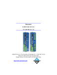
Model 4300
Model 7400
Model 7000XL
Model 8000XL
INSTRUCTION MANUAL
DORAN SCALES, INC.
1315 PARAMOUNT PKWY.
BATAVIA, IL 60510
1-800-262-6844
FAX: (630) 879-0073
http://www.doranscales.com
MANUAL REVISION: 2.0
MAN0239
4/11/2007
2
Table of Contents
Table of Contents ........................................................................................ 3
Introduction.................................................................................................. 8
Scale Operation ......................................................................................... 10
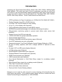
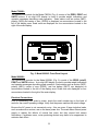
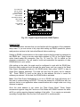
Fig. 1: Model 7400 Front Panel Layout ................................................................... 10
Model 7400: ............................................................................................................... 10
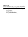
Fig. 3: Model 4300 Front Panel Layout ................................................................... 11
Model 4300: ............................................................................................................... 11
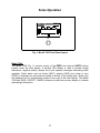
Fig. 4: Model 7000XL Front Panel Layout ............................................................... 11
Model 7000XL: ........................................................................................................... 12
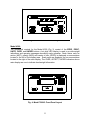
Fig. 5: Model 8000XL Front Panel Layout ............................................................... 12
Model 8000XL: ........................................................................................................... 12
Electrical Connections:............................................................................................... 12
Power Up: .................................................................................................................. 13
Basic Weighing Operation:......................................................................................... 13
ZERO button: ............................................................................................................. 13
UNITS button:(7400 optional)..................................................................................... 13
PRINT button:(7400 optional)..................................................................................... 14
4300 OVER / UNDER buttons:................................................................................... 14
Accumulator and Counter (Hidden button) ................................................................. 14
Battery Operation ...................................................................................... 16
Turn Off: (8000XL or Battery option) .......................................................................... 16
Low Battery Indication: (8000XL or Battery option) .................................................... 17
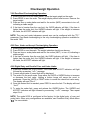
Checkweigh Operation ............................................................................. 18
7400 Zero Band Checkweighing Operation:............................................................... 18
4300 Over, Under and Accept Checkweighing Operation: ......................................... 18
4300 Digital Entry and Recall of Over and Under Limits: ........................................... 18
4300 Digital Entry of Over and Under Limits: (optional configuration)........................ 19
4300 Push-button Entry of Over and Under Limits: (optional configuration)............... 19
4300 Five Band Checkweighing Operation: (optional configuration).......................... 19
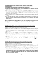
4300 Digital Entry and Recall of High and Low Limits:............................................... 20
4300 Digital Entry of High and Low Limits: (optional configuration) ........................... 20
4300 Push-button Entry of High and Low Limits: (optional configuration) .................. 21
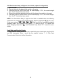
Serial Entry and Recall of Limits: ............................................................................... 21
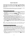
Setpoint Operation .................................................................................... 22
Digital Entry and Recall of Setpoint Limits:................................................................. 22
4300 Digital Entry and Recall of Setpoint Limits:........................................................ 22
Installation Guide ...................................................................................... 24
Fig. 6: Load Cell connections .................................................................................. 24
Removing the Rear Panel .......................................................................................... 24
Replacing the Rear Panel .......................................................................................... 24
Load Cell and Power Connections: ............................................................................ 25
RS232 and Remote Switch Connections: .................................................................. 25
Fig. 7: Serial, Remote SWITCH and power Connections ........................................ 25
Calibration Guide ...................................................................................... 26
Entering Calibration and Parameter Setup Mode:...................................................... 26
3
Capacity: .................................................................................................................... 26
Resolution: ................................................................................................................. 27
Calibration: ................................................................................................................. 27
A/D Ranging:.............................................................................................................. 29
Table 1: Calibration requirements in raw counts ..................................................... 29
Parameter Setup........................................................................................ 30
Entering and Exiting the Calibration and Parameter Setup Mode: ............................. 30
Stepping through the menu parameters: .................................................................... 31
Changing a Parameter settings:................................................................................. 31
Parameter Review of Calibration and Setup Values: ................................................. 32
Legal for Trade Restrictions: ...................................................................................... 32
Audit Counters: .......................................................................................................... 32
Software part number and revision level: ................................................................... 32
Setup Parameters Explained.................................................................... 33
Capacity Setup Menu .............................................................................................. 34
Count By Setup Menu ............................................................................................. 34
Calibration Menu ..................................................................................................... 34
Digital Filter Setup Menu ......................................................................................... 35
Automatic Zero Tracking Setup Menu ..................................................................... 35
Motion Aperture Setup Menu .................................................................................. 36
Start Up Zero Setup Menu ...................................................................................... 36
Latching Zero Request Setup Menu........................................................................ 36
Latching Print Request Setup Menu........................................................................ 36
Printer Data Output Setup Menu ............................................................................. 37
Output Formats ....................................................................................................... 37
Baud Rate Setup Menu ........................................................................................... 37
Serial Data Handshaking Setup Menu .................................................................... 38
Scale Address (Scale ID number) .......................................................................... 38
Units Conversion Setup Menu................................................................................. 38
Start Up Units Selection Menu ................................................................................ 39
Push-button Function Setup Menu .......................................................................... 39
Operating mode Setup Menu .................................................................................. 40
Unit On Timer (Battery option only) ......................................................................... 40
Checkweighing Operation Menu ............................................................................. 41
Setpoint & Checkweight Entry Menu ....................................................................... 42
Threshold Level Menu............................................................................................. 42
Checklimit Entry Mode Menu (4300 mode only)* .................................................... 42
Over and Under Band Setup Menu (7400 mode only) ............................................ 43
Default all Scale Parameter settings ....................................................................... 43
ISP Mode................................................................................................................. 43
Test Mode Menu ..................................................................................................... 44
Calibration and Parameter Menu Exit...................................................................... 44
Data Communications .............................................................................. 45
Introduction to data communications:......................................................................... 45
Printer Modes:............................................................................................................ 46
Transmit on demand (tod): ..................................................................................... 46
Continuous print (CP):.............................................................................................. 46
Auto Print 1 (AP1): ................................................................................................... 46
Auto Print 2 (AP2): ................................................................................................... 46
4
Auto Print 3 (AP3): ................................................................................................... 47
Data output format:..................................................................................................... 47
"F0" Format: ............................................................................................................ 47
"2d" Format: ............................................................................................................ 47
"SSP" format:............................................................................................................ 47
"Fg" Format: ............................................................................................................ 47
"UPS" Format: .......................................................................................................... 48
"d3" Format: ............................................................................................................ 48
"Lb1 - Lb4" Format: ............................................................................................... 48
Print String Formatting: .............................................................................................. 48
Label Buffer Configuration.......................................................................................... 53
Label Buffer Default settings ...................................................................................... 54
Remote Setpoint Entry and Recall: ............................................................................ 54
Table 2: Doran serial protocol ................................................................................. 56
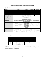
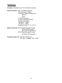
Specifications and Interconnect Data..................................................... 57
Specifications: ............................................................................................................ 57
Table 3: Scale Specifications .................................................................................. 57
Interconnect Data:...................................................................................................... 57
Table 4: TB1 Load Cell Connections....................................................................... 57
Table 5: P2 Options Connections............................................................................ 58
Fig. 10: RS232 Output DB9 Connector (optional) ................................................... 58
Table 6: Serial Output pin description ..................................................................... 58
Table 7: P3 Keyboard Connections......................................................................... 58
Table 8: J1 Power Connections .............................................................................. 59
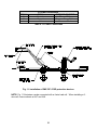
Fig. 11: Installation of EMI / RFI / ESD protection devices. ..................................... 59
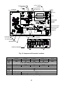
Fig. 12: Jumpers and Connector Locations............................................................. 60
Table 9: Board Jumper Settings .............................................................................. 60
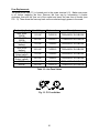
Fuse Replacement: .................................................................................................... 61
Table 10: Line Fuse Values..................................................................................... 61
Fig. 13: F1 Fuse Holder........................................................................................... 61
4-20mA Analog Output (optional)............................................................ 62
Introduction ................................................................................................................ 62
Setup.......................................................................................................................... 62
Operation ................................................................................................................... 62
Fig. 14.1: 4-20mA Analog Option Board.................................................................. 62
Fig. 14.2: Example of a Active 4-20mA circuit. ........................................................ 63
Fig. 14.3: Example of a Passive 4-20mA circuit. ..................................................... 63
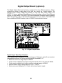
Digital Output Board (optional)................................................................ 64
Fig. 15.1: Digital Output Board ................................................................................ 64
Digital Output Board Specifications: ........................................................................... 64
Fig. 15.2: Digital Output Board Installed.................................................................. 65
Fig. 15.3: Digital Output Board Jumper Locations ................................................... 65
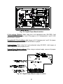
RS485 Communications (optional).......................................................... 66
Fig. 16.1: Digital Output Board with RS485 Option ................................................. 67
RS485 SETUP ........................................................................................................... 67
Table 11: RS485 Option Specification..................................................................... 68
Table 12: RS485 Termination Resistors.................................................................. 69
Fig. 16.2: RS485 two wire system ........................................................................... 69
Internal Relay Option (optional)............................................................... 70
5
Fig. 17: Digital Output Board Wiring ........................................................................ 70
Fig. 18: Internal Relay Board................................................................................... 70
Internal Relay Setup:.................................................................................................. 71
Relay Specifications:.................................................................................................. 71
Table 13: Internal Relay Output Cable Color Code ................................................. 71
Step-up Relay Circuit: ................................................................................................ 72
Fig. 19: Example of a Step-up Relay circuit. ........................................................... 72
External Relay Box Option (optional) ..................................................... 73
Fig. 20: External Relay Box..................................................................................... 73
Fig. 21: Knock-out Plugs ......................................................................................... 74
External Relay Setup: ................................................................................................ 74
Fig. 22: Mechanical Relay Module .......................................................................... 74
Table 14: Scale Signal Cable Color Code ............................................................... 75
Digital Output Board Setup:........................................................................................ 75
Fig. 23: Digital Output Board Wire and Jumper locations........................................ 75
Wired Ethernet Option (optional)............................................................. 76
Features and Applications:......................................................................................... 76
Fig. 24: RJ-45 Ethernet connector........................................................................... 76
Specifications: ............................................................................................................ 76
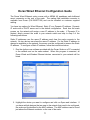
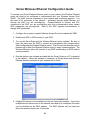
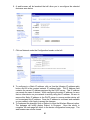
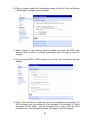
Doran Wired Ethernet Configuration Guide ........................................... 77
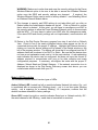
Module LED Description............................................................................................. 79
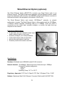
Wireless 802.11b Ethernet Option (optional) ......................................... 80
Fig. 25: Wireless Ethernet Antenna......................................................................... 80
Features and Applications.......................................................................................... 80
Specifications: ............................................................................................................ 81
Doran Wireless Ethernet Configuration Guide ...................................... 82
Module LED Description............................................................................................. 85
WPA – Pre-Shared Key.............................................................................................. 87
WPA – Authentication ................................................................................................ 87
Factory Configuration Data Sheet ........................................................................... 87
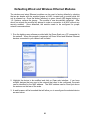
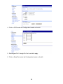
Defaulting Wired and Wireless Ethernet Modules................................. 88
Connecting to a scale through a web page ................................................................ 92
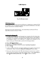
USB Option ................................................................................................ 93
Fig. 26: USB option board ....................................................................................... 93
USB Windows Drivers ................................................................................................ 93
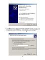
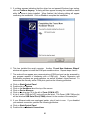
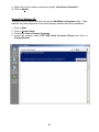
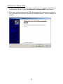
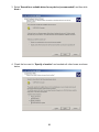
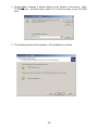
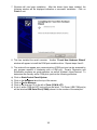
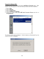
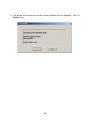
Installation For Windows XP:...................................................................................... 93
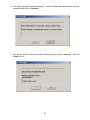
Removal For Windows XP: ........................................................................................ 96
Installation For Windows 2000: .................................................................................. 98
Removal For Windows 2000: ................................................................................... 102
Dimension Software................................................................................ 104
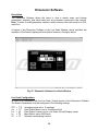
Description: .............................................................................................................. 104
Fig. 27: Dimension Software Live Scale Window .................................................. 104
Live Scale Configuration: ......................................................................................... 104
Troubleshooting ...................................................................................... 105
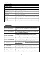
General problem resolution: ..................................................................................... 105
Scale Messages:...................................................................................................... 106
Error Messages:....................................................................................................... 106
Resetting the scale parameters:............................................................................... 107
6
Resetting the scale:.................................................................................................. 107
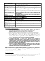
UPS Application Note ............................................................................. 108
Description: .............................................................................................................. 108
Hardware Setup: ...................................................................................................... 108
Software Setup:........................................................................................................ 108
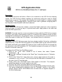
Grading Products Application Note ...................................................... 110
Grade and show product weight (gSt): .................................................................... 110
Grade and show grade number (gnt): ..................................................................... 110
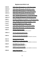
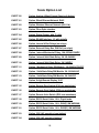
Replacement Part List............................................................................. 112
Scale Option List ..................................................................................... 116
7
Introduction
Introducing the Doran Scales Excel Series, Model 7400, 4300, 7000XL, 8000XL Digital
Scale Indicator. This scale uses state of the art technology to provide you with a low
cost solution to the most demanding weighing applications. With ease of use and setup
in mind, the scale is simple to set up and ready to use. The Model 7400, 4300, 7000XL,
8000XL offers many features. A few of these features are listed below:
NTEP certification for Class III installations to 10,000d (CoC 99-129A2 & 97-038A1).
Display Resolution from 250 to 50,000 divisions.
A six digit, 0.56" red LED display for easy reading.
lb, kg, oz, g, lb-oz display units supported.
Fully configurable duplex printer port with RS232 support.
EEPROM nonvolatile data storage of all calibration and setup information.
Microprocessor monitoring system to prevent scale failure under severe fault
conditions.
Support for up to four 350 ohm load cells.
115/230 VAC 50/60 Hz (jumper selectable) operation.
Field selectable digital filtering.
Software configurable remote push-button support (Optional).
Non NTEP parameters are user configurable.
Password protected, Front Panel Calibration Access Feature (Optional on 7400).
60 hour of battery operation, with built in charger (8000XL or Optional on other
models).
Six digit, 0.56" red LED remote display (Optional).
4-20mA analog output (Optional).
Wired Ethernet Communication port (Optional).
Wireless Ethernet Communication port (Optional).
RS485 Communication port (Optional)
USB Communication port (Optional)
Four Internal Mechanical or Solid State Relay outputs for non-battery models
(Optional)
Eight External Relay outputs for non-battery models (Optional)
Fiber Optic Communication (Optional)
Multi-tone Audible Alarm (Optional)
Peak and Hold, Product Grading software
Please be sure to read the entire manual to ensure obtaining all the benefits that the
Excel Series can provide. If any questions arise, please feel free to contact the Doran
Scales Technical Support Department at 1-800-262-6844.
8
Unpacking Your Scale
Before unpacking your Doran scale, please read the instructions in this section. Your
new scale is a durable industrial product, but it is also a sensitive weighing instrument.
Normal care should be taken when handling and using this product. Improper handling
or abuse can damage the scale and result in costly repairs that will not be covered by
the warranty. If you notice any shipping damage, notify the shipper immediately. Please
observe the following precautions to insure years of trouble free service from your new
scale.
DO NOT drop the scale.
DO NOT immerse the scale.
DO NOT drop objects on the platform.
DO NOT pick up the scale by the "spider."
Carefully remove the scale from the shipping carton.
9
Scale Operation
7400
UNDER
ACCEPT
OVER
NEG
lb
ZERO
kg
BATT
oz
MOT
g
ZERO
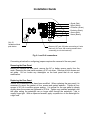
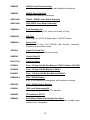
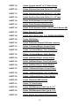
Fig. 1: Model 7400 Front Panel Layout
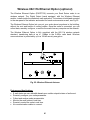
Model 7400:
The Model 7400 (Fig. 1) controls consist of the ZERO and optional UNITS buttons
located under the main display. A six-digit LED display is used to provide weight
indications, negative polarity (except lb/oz) and operator messages describing scale
operation. Scale status such as motion (MOT), polarity (NEG) and center of zero
(ZERO) is displayed on annunciators located to the left of the display area. Scale units
are displayed on four annunciators located to the right of the main display. The Model
7400 has OVER, ACCEPT, UNDER indicators located above main display to indicate
checkweight information.
10
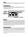
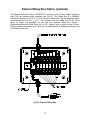
Fig. 3: Model 4300 Front Panel Layout
Model 4300:
The operational controls for the Model 4300 (Fig. 3) consist of the ZERO, PRINT,
UNITS, OVER, and UNDER buttons. A six digit LED display is used to provide weight
indications and operator messages describing scale operation. Scale status such as
motion (MOT), polarity (NEG) and center of zero (ZERO) is displayed on annunciators
located to the left of the display area. Scale units are displayed on four annunciators
located to the right of the main display. The OVER, ACCEPT, UNDER indicators above
main display are use to indicate checkweight information.
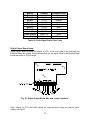
Fig. 4: Model 7000XL Front Panel Layout
11
Model 7000XL:
The operational controls for the Model 7000XL (Fig. 4) consist of the ZERO, PRINT and
UNITS buttons. A six digit LED display is used to provide weight indications and
operator messages describing scale operation. Scale status such as motion (MOT),
polarity (NEG) and center of zero (ZERO) is displayed on annunciators located to the
left of the display area. Scale units are displayed on four annunciators located to the
right of the main display.
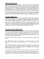
Fig. 5: Model 8000XL Front Panel Layout
Model 8000XL:
The operational controls for the Model 8000XL (Fig. 5) consist of the ZERO (on/off),
PRINT and UNITS buttons. A six digit LED display is used to provide weight indications
and operator messages describing scale operation. Scale status such as motion (MOT),
polarity (NEG), center of zero (ZERO), and low battery (BATT) are displayed on
annunciators located to the left of the display area. Scale units are displayed on four
annunciators located to the right of the main display.
Electrical Connections:
Prior to connecting your scale to power, check the serial number tag on the back of
scale for the correct operating voltage. Verify that the power matches the rated voltage.
Be sure the AC power is not excessively noisy - this can occur if large inductive loads,
such as solenoids or motors, are on the same power line. The scale has a filtered power
supply to reduce the effects of normal line noise, but they cannot limit severe
fluctuations. If problems occur, noise producing devices may have to be suppressed to
minimize their effect.
12
Power Up:
Connect the Model 7400, 4300, 7000XL to a compatible power source. With the 8000XL
or scale models with battery option, press and release ZERO button to turn on scale.
Basic Weighing Operation:
1) Remove all items from the scale platter.
2) Press the ZERO button to zero the scale. The weight display should now read zero.
3) Place an item on scale platter and wait for the motion (MOT) annunciator to go out,
indicating a stable weight.
4) Read the weight on the scale display.
ZERO button:
The ZERO push button is also used to zero the scale prior to making a reading. The
ZERO button functions over the full range of the scale in standard operation mode. In
Legal For Trade mode, it will be limited to a zero band equal to + 1.9% of scale capacity.
When the indicated weight is within the center of zero band (gross zero + 0.25 divisions)
the zero annunciator will light. To zero the scale, wait until the scale is stable and press
the ZERO button. The scale will not zero if the scale is in motion. Motion is indicated
when the MOT annunciator is lit. The scale is equipped with an optional "Zero on
Demand" feature which zeros the scale upon the next stable reading. This option may
be activated during the scale setup procedure.
UNITS button:(7400 optional)
The UNITS button permits the operator to select from six displayed weight units. Simply
press the UNITS button and the units annunciator will indicate the correct weight in the
current weight units "lb", "kg'', "oz", "g", "lb-oz". The UNITS button can be configured to
allow the selection of any combination of units listed above, preventing accidental
selection of undesired units. See the Units Conversion Setup Parameter for details.
The UNITS button has a parameter located in the Push Button Function Setup, which
can disable the UNITS button, and control the startup units selection every time the
scale is turned on.
13
PRINT button:(7400 optional)
The PRINT button permits the operator to send data to a printer or other external
devices. The user must wait for motion to stop before pressing the PRINT button.
Motion is indicated when the MOT annunciator is lit. The current weight will then be
transmitted to the printer. When the data is transmitted, the left most display digit will
momentarily display a "r" to confirm data transmission. The 4300, 7000XL, 8000XL, and
7400(optional) has a "Print on Demand" feature which stores a PRINT request until the
scale is stable. Once stable, the scale transmits the current weight. These models also
have several automatic print options, which may be used to simplify printer operation.
See the Data Communication Section for details on Further configuration. The PRINT
button is active with RS-232, RS-485, Ethernet and wireless communication protocols.
4300 OVER / UNDER buttons:
The OVER and UNDER buttons are used to enter the weight values needed for
checkweighing applications. In the simplest configuration (3 band), these buttons will
enter the “check” weight by pressing either the OVER or UNDER button. When in this
mode, the current weight is entered as the checkweighing limits. The default entry
mode uses the OVER and UNDER buttons to take the current weight and scroll it up or
down (arrows on the button indicate the scroll direction) until the desired “check” weight
is reached. Once the desired value is reached, pressing ZERO (ENTER) will enter the
desired value in the scale. The 4300 also offers five band check weighing.
Accumulator and Counter (Hidden button)
Press the Capacity Label to enter the accumulator / count recall mode. The display will
show "Accunn" followed by the accumulated weight, then "Countr" follow by the counter
value. The display will continue to repeat this message until a key is pressed. The
accumulator / counter recall mode will display the accumulator value in the units
currently selected in the weigh mode. Note: Changing the current display units will clear
both the accumulator and counter values.
Press UNITS button to exit the accumulator / counter recall mode without changing their
values.
Press ZERO button, while in the accumulator / counter recall mode to clear the
accumulator and counter values. The display will show "Clr Ac" and exit from the recall
mode.
Press PRINT button, while in accumulator recall mode, to transmit the accumulator and
counter values. Label buffer 4 contains the print string formatting for the accumulated
weight and counter value. See Output Formats in the Parameter section and Label
Buffer default settings for more details.
The accumulator and counter is incremented once every time a manual or automatic
accumulation occurs. When the weight has been added to the accumulator and the
counter has been incremented, the left most display digit will momentarily display a "o"
to confirm operation. The maximum value that can be shown for the accumulator and
14
counter is 6 digits or 999999. When the maximum value is reached, the accumulator or
counter will rollover. Note: The accumulator and counter feature can only be used in a
non Legal For Trade application.
15
Battery Operation
The 8000XL and other models with battery option are equipped with a self-contained
Rechargeable Sealed Lead-Acid battery and charging circuit, both internal. The scale is
designed to run continuously for 60 hours (with one 350 ohm loadcell) on a fully charged
battery. To significantly extend this battery life, enable the Unit On Timer which will
power down the scale automatically after a period of non-use. Multiple load cells, Fiber
Optic, Ethernet, 4-20mA, Wireless Communication(12 hours), Remote Display or Relay
options will reduce battery life. For multiple load cell applications, battery life is
significantly reduced. For example, with a four, 350
load cell configuration, the low
battery indication will begin at about 39 hours of continuous use. Load cells with higher
input impedance values such as 1000 will add up to 8 hours of additional battery life.
The charging circuit will fully charge the battery in approximately four to eight hours
whether the scale is on or off. To charge the battery, simply plug the line cord into a
standard 115V (230V optional) wall outlet. The scale can be used while recharging the
battery, in fact, the scale can be used with the AC charger cord plugged in on a
continuous basis. Note: 8000XL installed with multiple load cells, Fiber Optic, Ethernet,
4-20mA, Wireless Communication, Remote Display or Relay options will increase
charge time.
If an AC power failure occurs with the charger plugged in, the scale's battery
immediately takes over to provide uninterrupted scale operation.
The scale's charging circuit is a two-stage, current limited charger. The scale will sense
the charge condition of the battery and charge at a high rate when the battery is
depleted. When the battery comes up to a fully charged state, the charger will switch to
a trickle mode which maintains the battery at a fully charged state without overcharging.
The "BATT" annunciator indicates that the battery is in need of recharging. The scale
will continue to operate accurately for approximately one hour (with one 350 ohm
loadcell) after the "BATT" annunciator is lit. When the battery is too low to run the scale,
the scale simply turns off and will not operate again until the battery is recharged. At this
point, when the ZERO (ON/OFF) is pressed, the "BATT" annunciator will be lit as the
scale performs its display test and then the scale will shut down immediately.
The battery should be able to support at least 300 recharges before the end of the
battery life is reached. This is an estimate as many factors can affect battery life like,
severe temperature changes and charging before the scale's displays Low Battery.
Turn Off: (8000XL or Battery option)
1) To turn off manually, press and hold the ZERO push button until the display shows
"rEL Pb." Then release, the ZERO button and, the scale will turn off.
2) The scale will turn off automatically at the end of the Unit On Timer setting when that
mode is selected (see Unit On Timer parameter).
16
Low Battery Indication: (8000XL or Battery option)
The "BATT" annunciator indicates that the battery is in need of recharging. Once the
"BATT" annunciator turns on, there will be approximately one more hour of battery life
before the scale shuts down. When the battery is too low to run the scale, the scale
simply turns off and will not operate again until the battery is recharged. The scale
remains accurate and useable even with the "BATT" annunciator on.
17
Checkweigh Operation
7400 Zero Band Checkweighing Operation:
1) Remove all items from the scale platter. Place the target weight on the scale.
2) Press ZERO to zero the scale. The weight display should now be zero. Remove the
target weight.
3) Place an item on scale platter and wait for the motion (MOT) annunciator to turn off,
indicating a stable weight.
4) If the item is heavier than the over limit, the OVER indicator will light, If the item is
lighter than the under limit, the UNDER indicator will light. If the weight is between
the limits, the ACCEPT indicator will light.
NOTE: The over and under tolerances around zero can be configured with the "O.U."
parameter. Zero Band checkweighing is the only checkweighing operation available for
the model 7400.
4300 Over, Under and Accept Checkweighing Operation:
1) Remove all items from the scale platter.
2) Press ZERO to zero the scale. The weight indication should now be zero.
3) Place an item on scale platter and wait for the motion (MOT) to turn off, indicating a
stable weight.
4) If the item is heavier than the over limit, the OVER indicator will light, If the item is
lighter than the under limit, the UNDER indicator will light. If the weight is between
the limits, the ACCEPT indicator will light.
4300 Digital Entry and Recall of Over and Under Limits:
1) Press and release the OVER button. The OVER and ACCEPT indicators will light
followed by momentary "over" message.
2) Current weight value of saved limit will be displayed.
3) The scale is in the scroll mode. Press either the OVER or UNDER button to increase
or decrease the limit value. Holding a button longer will cause the count to
accelerate. Press the UNITS or PRINT button to cancel the check limit value entry.
The display will read “abort.”
4) Once the desired limit is reached, press ZERO to save the limit. The display will read
“donE.”
5) To enter the under limit, press and release the UNDER button. The UNDER and
ACCEPT indicators will light followed by momentary "under" message. Then repeat
steps 2 to 4.
NOTE: The model 4300 is configured at the factory for the digital entry of over and
under limits. Other entry configurations are available, see Checklimit Entry Mode Menu
"C.E." for more details.
18
4300 Digital Entry of Over and Under Limits: (optional configuration)
1) Zero the scale.
2) If available, place an item with the desired weight on the scale.
3) Press and release the OVER button. The OVER and ACCEPT indicators will light
followed by momentary "over" message.
4) The scale is in the scroll mode. Press either the OVER or UNDER button to increase
or decrease the limit value. Holding a button longer will cause the count to
accelerate. Press the UNITS or PRINT button to cancel the check limit value entry.
The display will read “abort.”
5) Once the desired limit is reached, press ZERO to save the limit. The display will read
“donE.”
6) To enter the under limit, press and release the UNDER button. The UNDER and
ACCEPT indicators will light followed by momentary "under" message. Then repeat
steps 4 and 5.
NOTE: To digitally adjust platform weight for over and under limits, the Checklimit Entry
Mode "C.E." menu is set to "SCS" option. See Checklimit Entry Mode "C.E." menus for
more details.
4300 Push-button Entry of Over and Under Limits: (optional configuration)
1) Zero the scale.
2) Place an item with the desired over weight on the scale.
3) Press and release the OVER button. The OVER and ACCEPT indicators will light,
followed by displaying "over", the current weight, then “donE” to indicate the limit has
been saved.
4) Remove the over item and place an item with the desired under weight on the scale.
5) Press and release the UNDER button. The UNDER and ACCEPT indicators will light
followed by displaying "under", the current weight, then “donE”, to indicate the limit
has been saved.
NOTE: The Push-button entry of over and under limits ("PB") is an optional configuration
in the Checklimit Entry Mode Menu. See Checklimit Entry Mode parameter ("C.E.") for
more details.
4300 Five Band Checkweighing Operation: (optional configuration)
1) Remove all items from the scale platter.
2) Press ZERO to zero the scale. The weight display should now be zero.
3) Place an item on scale platter and wait for the motion (MOT) annunciator to turn off,
indicating a stable weight.
4) If the item is heavier than the high limit, the OVER indicator will flash. If the item is
heavier than the “over” limit but lighter than the “high” limit, the OVER indicator will
turn on. If the item is lighter than the low limit, the UNDER indicator will flash. If the
item is heavier than the low limit but lighter than the under limit, the UNDER indicator
will turn on. If the weight heavier than the under limit but lighter than the over limit,
the ACCEPT indicator will light.
19
NOTE: The Five band checkweighing operating mode ("5BA", "5BS", "5Bt", "5Bb") is
available in four different optional configurations in the Check Weighing Operation Mode
Menu. See Check Weighing Operation parameter "C.o." for more details.
4300 Digital Entry and Recall of High and Low Limits:
1) Press and hold the OVER button until the display shows "High" and the OVER and
ACCEPT indicators flash.
2) Current weight value of saved limit will be displayed.
3) Press either the OVER or UNDER button to increase or decrease the limit value.
Holding a button longer will cause the count to accelerate. Press UNITS or PRINT to
cancel the check limit value entry. The display will read “abort.”
4) Once the desired limit is reached, press ZERO to save the limit. The display will read
“donE.”
5) To enter the UNDER limit, press and hold the UNDER button until the display shows
"louu" and the UNDER and ACCEPT indicators flash.
6) Then follow steps 2 to 4.
NOTE: To digitally enter in high and low limits, the following parameters must be
configured. The Check Weighing Operation parameter "C.o." set to any of the menu
options ("5BA", "5BS", "5Bt", "5Bb") that has the five band check weighing operating
mode. The Checklimit Entry Mode "C.E." menu is set to "SCr" option. See Check
Weighing Operation "C.o." and Checklimit Entry Mode "C.E." menus for more details.
4300 Digital Entry of High and Low Limits: (optional configuration)
1) Zero the scale.
2) If available, place an item with the desired weight on the scale.
3) Press and hold the OVER button until the display shows "High" and the OVER and
ACCEPT indicators flash.
4) Press either the OVER or UNDER button to increase or decrease the limit value.
Holding a button longer will cause the count to accelerate. Press UNITS or PRINT to
cancel the check limit value entry. The display will read “abort.”
5) Once the desired limit is reached, press ZERO to save the limit. The display will read
“donE.”
6) To enter the UNDER limit, press and hold the UNDER button until the display shows
"louu" and the UNDER and ACCEPT indicators flash.
7) Then follow steps 4 and 5.
NOTE: To digitally enter in high and low limits, the following parameters must be
configured. The Check Weighing Operation parameter "C.o." set to any of the menu
options ("5BA", "5BS", "5Bt", "5Bb") that has the five band check weighing operating
mode. The Checklimit Entry Mode "C.E." menu is set to "SCS" option. See Check
Weighing Operation "C.o." and Checklimit Entry Mode "C.E." menus for more details.
20
4300 Push-button Entry of High and Low Limits: (optional configuration)
1) Zero the scale.
2) Place an item with the desired high weight on the scale.
3) Press and hold the OVER button until the scale displays "High", the current weight
then “donE.” The limit has been saved.
4) Remove the high item and place an item with the desired low weight on the scale.
5) Press and hold the UNDER button until the scale displays "Louu", the current weight,
then “donE”. The limit has been saved.
NOTE: The Push-button Entry of high and low limits is available when the following
parameters are configured. The Check Weighing Operation parameter "C.o." set to any
of the menu options ("5BA", "5BS", "5Bt", "5Bb") that has the five band check weighing
operating mode. The Checklimit Entry Mode "C.E." menu is set to "Pb" option. See
Check Weighing Operation "C.o." and Checklimit Entry Mode "C.E." menus for more
details.
Serial Entry and Recall of Limits:
All limits (setpoint values) can be entered or recalled by way of serial port using the ESx
and RSx commands. Were x would be the setpoint number 1 - 8. See Data
Communication Section for further information.
21
Setpoint Operation
All scale models can be configure to Setpoint Operation. The Setpoint Operation is
available when the following parameters are configured. The Check Weighing Operation
parameter "C.o." set to any of the menu options "5EA" or "5ES". The eight available
outputs on the optional Digital Output Board are nominally configured to each of the
Setpoint limits.
There are two different methods of Setpoint entry of limits. The first method is available
on all models and the second method is only available on the model 4300.
Digital Entry and Recall of Setpoint Limits:
1) The entry and recall of Setpoint limits is performed by entering the Calibration mode.
Press and release UNITS button until the display shows "C.E. no" for Setpoint Entry
menu prompt.
2) Press ZERO button to select yes option "C.E. yES" and then UNITS button to enter
the Setpoint Entry menu. The display will show the "SP1 AJ" message for Setpoint 1
Adjustment option.
3) Press and release the ZERO button to recall saved Setpoint 1 limit value.
4) With the limit value showing, the scale is now in the scroll mode.
5) Press either the OVER or UNDER button to increase or decrease the limit value.
Holding a button longer will cause the count to accelerate. Press UNITS or PRINT to
cancel the check limit value entry. The display will read “abort.”
6) Once the desired limit is reached, press ZERO to save the limit. The display will
return back to showing the current Setpoint Adjustment message “SP1 AJ”.
7) To enter in the next Setpoint limit, press and release the UNDER button. The display
will show "SP2 AJ" message for Setpoint 2 Adjustment option. Then repeat steps 3
to 5.
NOTE: To select a different Setpoint limit number. Use the UNITS button to scroll
through the 8 available Setpoint Adjustment numbers to enter or recall their limit value.
4300 Digital Entry and Recall of Setpoint Limits:
1) Press and release the UNDER button, the display will show "Spt1" message.
2) Press and release the ZERO button to recall saved Setpoint 1 limit value.
3) With the limit value showing, the scale is now in the scroll mode. Press either the
OVER or UNDER buttons to increase or decrease the limit value. Holding a button
longer will cause the count to accelerate. Press the UNITS button to cancel the
Setpoint limit value entry. Press the UNITS or PRINT button to cancel the Setpoint
limit value entry. The display will read “abort.”
4) Once the desired limit is reached, press ZERO to save the limit. The display will read
“donE.”
5) To enter in the next Setpoint limit, press and release the UNDER button and then the
OVER button to select Setpoint 2 limit. The display will show "SPt 2" message.
Then repeat steps 2 to 4.
22
NOTE: To select a different Setpoint limit number. Use the UNITS or UNDER buttons to
scroll through the eight available Setpoint Adjustment numbers to enter or recall their
limit value.
NOTE: To digitally enter in Setpoint limits, the following parameters must be configured.
The Checklimit Entry Mode "C.E." menu is set to "SCS" option. See Checklimit Entry
Mode "C.E." menus for more details.
23
Installation Guide
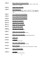
+ Signal (Red)
- Signal (White)
+ Excitation (Green)
- Excitation (Black)
+ Sense (Blue)
- Sense (Brown)
CAL S1
Calibration Mode
push button
Remove JU7 and JU8 when connecting a 6-wire
load cell. (JU7 and JU8 must be present when
connecting to a 4-wire load cell)
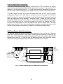
Fig. 6: Load Cell connections
Connecting a load cell or configuring jumpers requires the removal of the rear panel.
Removing the Rear Panel
Before you remove the rear panel, remove the AC or battery power supply from the
scale. Removing the rear panel requires a 5/16” nut driver. Remove all four screws and
set aside. Do not loosen any watertights on the back panel that do not require
modification.
Replacing the Rear Panel
Secure any connections that have been modified. When replacing the rear panel it is
necessary to mount the gasket, all four screws and gasket washers. Tighten all four
screws to 20 ft-lb to achieve proper sealing. It is normal for the rear panel to dimple
slightly when the screws are tightened to 20 ft-lb. Tighten any modified watertight until
the cable exiting the watertight can no longer slide through the watertight – this is
usually finger tight. With an open-end wrench, apply a quarter turn to the watertight for
a tight seal.
24
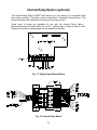
Load Cell and Power Connections:
Load cell connections are made through a terminal block "TB1" located at the bottom
center of the main board (see Fig. 6). The power cord connects to a connector "J1"
adjacent to the transformer (see Fig. 7). These connections are accessible by removing
the rear cover screws and laying the rear panel and front of scale on the work surface.
To install a single load cell, remove the rear panel and check the JU7 and JU8 jumper
configuration. Remove JU7 and JU8 for a six-wire load cell. Inversely, JU7 and JU8
must be in place for a four-wire load cell. Locate the ferrite core kit and read "load cell
cable grounding and ferrite assembly" instruction sheet. Thread the load cell wires
through the ferrite core as shown in Fig. 11. Connect the load cell wires by inserting the
tip of a screw driver into the round hole located on the top of the terminal block TB1.
Use the screw drive blade to open the adjacent slot, insert a striped end of a single
loadcell wire into slot. Once wire end has been inserted, remove screw driver, wire
should now be capture in terminal slot. Repeat for all remaining loadcell wires.
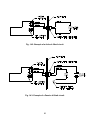
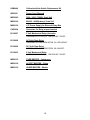
RS232 and Remote Switch Connections:
The Remote Switch and Serial Communications terminal is found on the top of the main
board next to the transformer. These option connections are accessed by removing the
rear cover. Connections are made by inserting each lead of the option cable into P2
terminal block (see Fig. 7). Like the load cell cable and power cord, the option cables
are passed through watertight fittings mounted on the back of the indicator.
HOT
GND
NEUTRAL
GND.
REMOTE SWITCH
SERIAL OUT (TXD)
SERIAL IN (RXD)
Fig. 7: Serial, Remote SWITCH and power Connections
25
Calibration Guide
Entering Calibration and Parameter Setup Mode:
The Calibration and Parameter Setup Mode can be entered by three different ways.
1) The Front Panel CAL Access Feature on power-up (Available only on the 4300,
7000XL, 8000XL models or on models that have an optional UNITS push button
installed.) To enter the calibration mode, power up the scale while pressing the
ZERO and the UNITS button at the same time. When the “rEL Pb” is shown, release
both buttons. The display will momentarily show “Ent Cd” then go blank. Press the
ZERO button five times, the display will indicate the number of times the button has
been pressed. When “ 5 “ is displayed then press and release the UNITS button and
wait a few seconds. Note: If the code is not entered before the timer is finished, the
scale will bypass code entry and enter the normal run mode. See Parameter Setup
section for more information.
2) The Front Panel CAL Access Feature after power-up (Available only on the 4300,
7000XL, 8000XL models.) To enter the calibration mode, first press and hold the
UNITS and then the ZERO button until the Audit counters and Parameter review
starts. After the Audit counters are displayed, and during the parameter review,
press and release the Hidden (Capacity Label) button. The display will momentarily
show “Ent Cd” then go blank. Press the ZERO button five times, the display will
indicate the number of times the button has been pressed. When “ 5 “ is displayed
then press and release the units button and wait a few seconds. Note: If the code is
not entered before the timer is finished, the scale will bypass code entry and enter
the normal run mode. See Parameter Setup section for more information.
3) The CAL switch S1 is a momentary push button located in the lower left corner of
main PC. Board (see Fig. 6). To access the calibration switch remove the meter’s
back cover.
Capacity:
The Capacity selection is performed by entering the Calibration mode. Press and
release UNITS button until the display toggles between "CAP Aj" and the current
capacity "XXXXXX" (where "XXXXXX" can be any valid capacity in lb or kg. The units
annunciator to the right of the weight display will indicate either lb or kg. The Calibration
and capacity setup unit is defined by the startup units "S.U." parameter setting.)
Once the current capacity appears, press and release ZERO button to begin capacity
adjustment. The first display digit located all the way to the right, will begin to flash.
Press ZERO to increment value of digit. Press UNITS to select the next digit (shift left),
or PRINT to select the previous digit (shift right). The digit that has been selected will
starting flashing. To enter a decimal point for the selected digit,. Press and hold the
UNITS button, then press ZERO to toggle the decimal point on or off. Once the desired
capacity is displayed, press UNITS until "Cnt by" parameter is displayed. When
finished, return to the run mode by pressing the CAL switch or scroll through the menu
with the UNITS button to "donE n". Select "donE y" by pressing the ZERO button, and
then press the UNITS button to exit to the run mode.
26
Once the desired capacity has been selected, place the correct capacity label on the
front panel, to the right of the display.
NOTE: On scales with factory installed platforms, the capacity is set at the factory. It will
not be necessary to set the scale capacity.
Resolution:
After Capacity has been entered, the scale's Resolution (Count-By) will automatically be
set for a nominal 5000 division level. To enter in a different Count-by setting, the scale
must be in the Calibration mode. Press and release the UNITS button until the display
momentarily shows "Cnt by" and then starts flashing the current Resolution level
"XXXXXX" (where "XXXXXX" can be any valid count-by value between 100 and 45,000
divisions of capacity. The units annunciator to the right of the weight display will indicate
either lb or kg.
Once the current Count_By level appears, press and release ZERO button to increment
value through the available range. Once maximum level has been reached, the level will
roll-over to the minimum value. When finished, return to the run mode by pressing the
CAL switch or scroll through the menu with the UNITS button to "donE n". Select "donE
y" by pressing the ZERO button, and then press the UNITS button to exit to the run
mode.
Calibration:
1. Enter Calibration mode, then press and release the UNITS until "CAL 0" appears on
the display.
2. Remove all weight from the scale platter and wait for about 10 seconds. Press
ZERO and wait for the display to count down to 0. If the calibration zero was in
range, the display will return with "CAL FS". If the display returns with a "CAL 0",
repeat the process.
NOTE: If "rg Err" appears on the display, the calibration zero is out of range. Press
ZERO to clear error. Refer to the A/D Ranging section for additional information.
The scale can be calibrated using (a) full capacity weight, (b) half capacity, (c) quarter
capacity, (d) one tenth capacity, or (e) any capacity weight between 2% and 100% of
full scale (Not available on the 7400).
To select the weight to calibrate the scale, press the UNITS button and select one of the
four following capacities.
CAL
CAL
CAL
CAL
FS: Full load calibration.
.50: Half load calibration. (50% of full load)
.25: Quarter load calibration. (25% of full load)
.10: 1/10th load calibration. (10% of full load)
27
If you want to select a weight between 2% and 100% of capacity, select the capacity
range above closest to the desired weight. Then scroll to the exact weight by pressing
CAPACITY to go increase the weight or PRINT to reduce the weight. This is not
available on the Model 7400.
3. To complete the calibration process, place the correct weight on the platter and
press ZERO and wait for the display to count down to 0. If the span calibration was
in range, the display will return with "donE". If the display returns with a "CAL 0",
repeat steps 2 and 3.
NOTE: If "Er nEg" appears on the display, the calibration span is in a negative range.
Check polarity of load cell connection (see Fig. 6) and repeat Calibration.
NOTE: If "SPAn E" appears on the display, the calibration span is out of range. Press
ZERO to clear this error. Refer to the A/D Ranging section for additional information.
NOTE: Calibration at 2% of capacity has been provided as a convenience to customers
with high capacity scales in remote or inaccessible locations. Scales calibrated at 2% of
capacity are more likely to have significant errors at full capacity than are scales
calibrated at 25% or 50%. Doran Scales recommends that all scales be calibrated at
full capacity whenever possible. 2% calibration should not be used when calibrating
scales for legal for trade applications. It is the responsibility of the installer/user to
ensure that NTEP accuracy is achieved after any calibration.
28
A/D Ranging:
(Refer to this section only if you encounter a calibration problem)
NOTE: On scales with factory installed platforms, the zero and span will lie within
permissible limits. Load cell signal input range 0.283 mV/V to 5 mV/V.
1) Enter Calibration mode by using Front Panel CAL Access feature or by
pressing the CAL switch (S1).
2) Press and release UNITS or PRINT until in the raw counts mode.
3) Return the scale platform to "No Load" by removing all items from the platform.
4) Record the "No Load" counts. The "No Load" or dead load raw counts must be
between 130,000 and 393,000 counts. If the readings are outside of the limits
specified, change dead load until you meet these requirements.
5) Place "Full Load" on the platform and record the "Full Load" counts. Subtract
the "No Load" counts from the "Full Load" counts to calculate the "span". Refer
to Table 1 and verify that the span falls within the limits specified range. The
"Full Load" raw counts (span + dead load) should not exceed 900,000 counts.
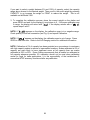
6) When using 50%, 25% or 10% of full load to calibrate, refer to Table 1 for Full,
50%, 25%, 10% span ranges.
Calibration requirements in raw counts
Platform load
Minimum span
Maximum span
Full
30,000
500,000
50%
15,000
250,000
25%
7,500
125,000
10%
3,000
50,000
Table 1: Calibration requirements in raw counts
29
Parameter Setup
The Excel Series has 54 calibration and parameters setup menu items, which can be
accessed three different methods, CAL switch and the Front Panel CAL Access Feature
on both power-up or after power-up. The Front Panel CAL Access Feature allows the
user to change the scale’s calibration and parameter settings by way of entering in a
password code. This Feature is only available when scale is not configured for legal for
trade Switch mode (see Operating mode Setup Menu).
Entering and Exiting the Calibration and Parameter Setup Mode:
The Calibration and Parameter Setup Mode can be entered by three different methods.
1) Front Panel CAL Access Feature during power-up
The Front Panel CAL Access Feature during power-up is only available when the
scale is in an Audit Trail mode (“oP” = “Std”, “44”, “PH”, "PHS", "PHt", "PSt", "GSt",
"Gnt"). This feature is not available on 7400 without the units push button option. To
enter the calibration mode, power up scale while pressing the ZERO and the UNITS
button at the same time. When the “rEL Pb” is shown, release both buttons. The
display will momentary show “Ent Cd” then go blank. Press the ZERO button five
times, the display will indicate the number of times the button has been pressed.
When “ 5 “ is displayed then press and release the UNITS button and wait a few
seconds. Note: If the code is not entered before the timer is finished, the scale will
bypass code entry and enter the normal run mode.
2) Front Panel CAL Access Feature after power-up
The Front Panel CAL Access Feature after power-up is only available when the
scale is in an Audit Trail mode (“oP” = “Std”, “44”, “PH”, "PHS", "PHt", "PSt", "GSt").
This feature is not available on the 7400 model. To enter the calibration mode, first
press the UNITS and then ZERO buttons and hold them until the parameter review
starts. After the Audit counters are displayed, press and release the Hidden
(Capacity Label) button. The display will momentary show “Ent Cd” then go blank.
Press the ZERO button five times, the display will indicate the number of times the
button has been pressed. When “ 5 “ is displayed then press and release the UNITS
button and wait a few seconds. Note: If the code is not entered before the timer is
finished, the scale will bypass code entry and enter the normal run mode.
3) Switch Access Mode
Scale must be in Legal for Trade Switch mode (“oP” = “44S”). Apply power to the
Scale. Then momentarily press the CAL switch S1 located in the lower left corner of
main PC. Board (see Fig. 6). The calibration switch can be accessed by removing
the meter’s back cover. Note: Parameter and Calibration audit counters will be
hidden when set in this mode. Warning: do not press CAL switch while powering up
scale, this will cause the scale to reset all parameter settings.
The scale will Momentarily display Parameter and Calibration audit counters (Audit Trail
mode only). The indicator will then display the first menu item, "CAL Aj" and "25"
30
(Where 25 can be any valid capacity in lb or kg). Press the UNITS button to access the
next menu item.
To exit the Calibration and Parameter Setup Menu, momentarily press the CAL switch
or scroll through the menu options, by pressing the UNITS button, until "donE n"
appears. Press ZERO button until "donE y" appears and then press the UNITS button.
The indicator will return to the normal weighing mode. If any menu selections were
changed, The new values will be saved
Note: No new setup information is saved until the scale displays "SAVEd" and returns to
the RUN mode. In the event of a power failure while in the Calibration and Parameter
Mode, any changes that have been made will be lost.
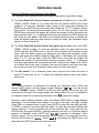
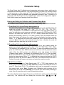
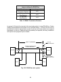
Stepping through the menu parameters:
Once the Calibration and Parameter Setup Mode has been entered, you may step
through the menu by pressing and releasing UNITS. Some items in the menu contain
sub menus (see below) which can be enter by selecting "yes" and pressing UNITS. A
different display prompt will appear for each parameter in the menu.
The Setup Parameters Explained on the following pages corresponds to the parameters
available in the Calibration Setup Menu.
UNITS
PRINT
Parameter 1
Parameter 2
Sub menu: no
Parameter X
ZERO
Value 1
Sub menu: yes
Parameter 3
Parameter 4
Value 1
Value 1
Value 2
Value 2
Value 3
Value 3
UNITS
ZERO
Value 2
Value 3
Value 4
PRINT
ZERO
Press CAL Switch
at any time to save
changes and exit
Calibration/Setup
Mode.
Changing a Parameter settings:
After finding the desired menu item (parameter), the settings for that parameter may be
changed. Press and release ZERO to scroll through the list of settings for that item. The
list of choices will repeat if you keep pressing and releasing ZERO. When you have
found the desired setting, press UNITS to go to the next menu item.
31
Parameter Review of Calibration and Setup Values:
The Parameters values for the indicator may be quickly reviewed without entering in the
Calibration and Parameter Setup Mode. Remove power and press and hold the ZERO
button while you apply power. Hold the button until the scale begins to scroll through
each of the parameters. The button may be released anytime after the review has
begun. After parameters are displayed, scale will then go to the normal weighing mode
automatically. Note: The Parameter and Calibration audit counters are the first item to
be displayed when the scale is in Legal for Trade / Audit Trail mode (“oP” = “44” ).
Legal for Trade Restrictions:
When the Legal for Trade mode is enabled, it automatically disables some menus and
parameter options. This is done to comply with NTEP requirements. The menus and
parameter sections are shown on the following pages. Those menus and/or parameters
not available when in the Legal for Trade mode are marked by an asterisk.
Audit Counters:
When entering calibration mode, the Parameter audit counter and the Calibration audit
counter will momentarily be displayed. The Parameter audit counter only increments
when CAP, Cnt by, A2t, nn.A., SU0, oP values are changed (ZERO pb is pressed). The
Calibration audit counter only increments when Calibration Zero CAL 0, and Span CALXX
are performed. Note: when scale is in Legal For Trade Switch mode (“oP” = “44S”), the
Audit counters will not be displayed.
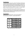
Software part number and revision level:
During power up, the scale will display several messages. The first message is a display
test with all the LED segments on, "888888". Next, the scale will show the software part
number "Su 102" followed by the software revision level "rEv 3.0" or higher. Please
have ready the software part "102" and the revision level, when contacting our service
department.
32
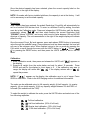
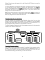
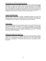
Setup Parameters Explained
C
Calibration Setup Menu
P
CAp aJ
Cnt by
Cal
Avg
A2t
nn.A.
SUO
2od
Pod
d.o.
For.
1
0.00002
0
A0
off
0.5
on
on
on
t.o.d.
F0
A9
0.5
1
CLO
off
off
A.P.1
f1
PbO
995000
5000
A7
1
3
A.P.2
2d
A6
3
5
A.P.3
ssp
A5
5
10
C.P.
f9
A4
xxxxxx
UPS
FS
A3
d3
.50
C4
Lb1
.25
C8
Lb2
.10
C16
Lb3
C32
Lb4
C64
HS
Adr
12
SF
0
24
off
48
Add
96
48S
br.
CSL
UnitS
no
lb
kg
oz
g
lb-oz
yes
99
14.4
P.b.
no
Yes
Ac
OU
Pr
Ut
2r
rt
on
on
on
on
on
off
off
off
off
off
off
2r
Pr
C.o.
Lb
hg
o2
g
Lo
on
on
on
on
on
off
off
off
off
off
S.E.
thS
C.E.
O.U.
dEft
0.1
op
tdy
Std
on
off
no
44
.5
oUA
yes
44S
1
oUS
PH
1.5
oUt
9.9
n
n
4nnA
n
y
y
20nnA
y
SCS
2
SP1
n
2 n
out 2
y
2 y
out 3
oUb
SP2
4
SP3
5
PSt
5
SBS
Lo
7
udr
out 1
3
SbA
30
donE
1
2
Gnt
xxxxxx
off
3
SBt
ISP
Pb
PHt
10
Ac
SCr
PHS
GSt
Ut
10
out 4
out 5
Default
ISP mode
out 6
Sbb
SP6
15
out 7
bnA
our
20
out 8
bnS
Hi
30
33
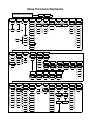
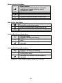
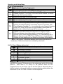
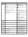
Capacity Setup Menu
Capacity Adjustment Menu
Allows the selection of scale capacity.
1 lb / kg to 999,000 lb / kg
Press ZERO in increase column value, UNITS to
1 - 999000 select next column, PRINT to select previous column,
UNITS & ZERO to toggle decimal point.
NOTE: Capacities > 60,000 lb, oz units are disabled.
Capacities > 2000 lb, grams units are disabled
Capacities > 1000 lb, lb-oz units are disabled
CAP Aj
Count By Setup Menu
Cnt By
0.00002
5000
Count By Setup Menu (Resolution)
Allows the selection of scale division size.
0.00002 lb / kg to 5000 lb / kg
Selection with be limited by capacity.
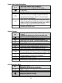
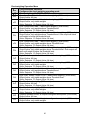
Calibration Menu
CAL
Zero Calibration Mode.
Calibration Zero
Press ZERO to perform calibration of the scale zero.
0
Successful calibration is indicated by "CAL FS"
NOTE: The scale will automatically adjust the offset and gain to
compensate for dead load and span. When making these adjustments,
the scale may ask you to repeat zero calibration immediately after
performing a zero calibration or after a span calibration. Successful
calibration is indicated by "CALMFS"
Span Calibration Mode.
(Does not appear if CAL 0 is not activated.)
Full load calibration.
FS
Half capacity calibration.
.50
Quarter capacity calibration.
.25
1/10th of capacity calibration.
.10
By pressing the hidden or print push button weight
value can be entered in. (note: XXXXXX will be the
XXXXXX
dialed in weight value. This feature is not available
on 7400.)
NOTE: For maximum accuracy, Doran Scales recommends that all
scales be calibrated at full capacity. When location or installation make
it difficult to bring full capacity weights to the scale, calibration with as
little 10% of capacity is possible.
CAL
34
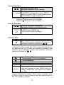
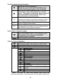
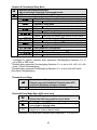
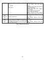
Digital Filter Setup Menu
Averaging mode
Avg
Determines the number of samples to average
Stabil-izer© auto averaging. All readings are
A0
averaged. Display updates 10 times a second.
Stabil-izer© auto averaging. All readings are
A9
averaged. Display updates 9 times a second.
Stabil-izer© auto averaging. All readings are
A7
averaged. Display updates 7 times a second.
Stabil-izer© auto averaging. All readings are
A6
averaged. Display updates 6 times a second.
Stabil-izer© auto averaging. All readings are
A5
averaged. Display updates 5 times a second.
Stabil-izer© auto averaging. All readings are
A4
averaged. Display updates 4 times a second.
Stabil-izer© auto averaging. All readings are
A3
averaged. Display updates 3 times a second.
Circular auto averaging, 2 readings are averaged.
C2
Display updates 20 times a second.
Circular auto averaging, 4 readings are averaged.
C4
Display updates 10 times a second.
Circular auto averaging, 8 readings are averaged.
C8
Display updates 5 times a second.
Circular auto averaging, 16 readings are averaged.
C16
Display updates 3 times a second.
Circular auto averaging, 32 readings are averaged.
C32
Display updates 1½ times a second.
Circular auto averaging, 64 readings are averaged.
C64
Display updates 1 time every 1.4 seconds.
NOTE: On the Circular auto averaging filter, when in motion only 4
readings are averaged.
Automatic Zero Tracking Setup Menu
Automatic Zero Tracking Range
Small weights within the specified number of
divisions are automatically zeroed.
Zero tracking is off. No automatic zeroing.
oFF
Zero tracking to within 0.5 division.
0.5
1*
Zero tracking to within 1.0 division.
3*
Zero tracking to within 3.0 divisions.
5*
Zero tracking to within 5.0 divisions.
* NOTE: The Legal for Trade mode disables some options and
selections listed above. These items have been indicated by an asterisk.
A2t
35
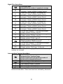
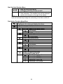
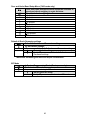
Motion Aperture Setup Menu
Motion aperture *
Determines how many divisions consecutive
nn.A.*
readings must change before the scale is
considered in motion.
0.5 division change must be seen to enter motion.
0.5
1 division change must be seen to enter motion.
1
3
division change must be seen to enter motion.
3
5 division change must be seen to enter motion.
5
10 division change must be seen to enter motion.
10
Start Up Zero Setup Menu
Start Up Zero
SU0*
Controls the start up zero status.
Zeros on the first stable reading on power up.
on
Loads
the calibration zero for zero reference
CL0
PB0*
Loads the last pushbutton zero. (Disabled in LFT mode)
Latching Zero Request Setup Menu
Zero on Demand
2od
Enables or disable zero latching.
If ZERO is pressed, it is saved until the scale becomes
on
stable.
If the scale is in motion, the zero request is
oFF
discarded.
Latching Print Request Setup Menu
Print on Demand
Pod
Enables or disables print latching.
If PRINT is pressed, the print request is saved until the
on
scale becomes stable.
If the scale is in motion, the print request is
oFF
discarded.
* NOTE: The Legal for Trade mode disables some options and selections
listed above. These items have been indicated by an asterisk.
36
Printer Data Output Setup Menu
Data Output Mode (see Print Modes)
d.o.
Determines when serial data will be sent.
Transmit on demand. Print when the PRINT button
t.o.d.
is pressed.
Auto Print 1. Print once only when scale goes stable.
A.P.1
Auto Print 2. Print once only when scale goes stable.
Scale must return to a negative weight or within the
A.P.2
adjustable threshold level, before it can print again.
(see Threshold Level Menu)
Auto Print 3. Print once only when scale goes stable
within the accept band. Scale must return to a negative
A.P.3
weight or within the adjustable threshold level, before
it can print again. (see Threshold Level Menu)
Continuous Print. Print when display is updated.
C.P.
(Disabled in RS485 mode)
Output Formats
For.
F0
F1
2d
SSP
F9
UPS
d3
Lb1
Lb2
Lb3
Lb4
tld
nci
NCI
Data Input / Output Format (see Data output
format)
Defines the appearance of the serial data sent.
Basic output format (8,n,1)
Enhanced output includes checkweigh status.
Basic Dual Print Format. Includes Kilogram weight.
Basic Output for Eltron printer
Model 8000 emulation
UPS World Ship format (7,o,2)(9600 baud)
Live Scale (Virtual) Display format ( set d.o. to C.P.)
Select label buffer 1 (user defined print string)
Select label buffer 2 (user defined print string)
Select label buffer 3 (user defined print string) (Used
for data collection with Comma-delimited format / CSV)
Select label buffer 4 (user defined print string) (Used
for Accumulator / Counter Print Command)
Toledo PS60 format. (7,o,2)
NCI 3825 format (7,e,1)(4800 baud)
NCI 3835 format (7,e,1)(4800 baud)
Baud Rate Setup Menu
Baud Rate Setup
br.
Determines baud rate for serial data.
1200
baud (bits per second)
12
2400 baud (bits per second)
24
4800 baud (bits per second)
48
9600 baud (bits per second)
96
14,400 baud (bits per second)
14.4
37
Serial Data Handshaking Setup Menu
Serial Data Output Handshaking
Selects the type of serial data handshaking used.
HS
(See the Data Communication section for details)
Software handshaking. Data is sent when ready.
Transmission can be controlled by the receiving
device. The software handshaking option activates BiSF
directional RS232 communications. Refer to the
communications section for details.
No handshaking is used. Data is sent when ready,
receiving device (printer) must be fast enough to keep up
oFF
with the data. Disables bi-directional communications.
Turns on Address mode. (All received serial commands
Add
require a 00-99 address preface.)
Turns on RS485 mode, print buffer & Address mode
(Disabled when Data Output is set for Continuous Print)
485
(See RS485 Communications for details.)
Scale Address (Scale ID number)
Selects scale (bus) address code.
An two digit ASCII number is required before scale
Adr
will respond to any serial input. (See RS485
Communications for details)
Press zero pb to scroll address from 0 through to 99
0-99
Units Conversion Setup Menu
Convert Select Modes
CSL
Determines which units selections will be active.
Do not enter Convert selection menu.
no
Enter Convert selection menu.
yes
pounds menu
lb
lb is active
on
lb is non active
off
kilograms menu
hg
kg is active
on
kg is non active
off
ounces menu
o2
oz is active
on
oz
is non active
off
grams menu
gr
g is active
on
g
is non active
off
pound-ounces menu (Disabled in LFT
Lo*
mode)
on*
lb-oz is active
off*
lb-oz is non active
* NOTE: The Legal for Trade mode disables some options and
selections listed above. These items have been indicated by an asterisk.
38
Start Up Units Selection Menu
Start Up Units Select Mode
UnitS
Configures selection of start up units.
Press ZERO to scroll through the units activated in the
Units parameter. The selected units will be displayed
on the units indicators to the right of the display.
NOTE: If an invalid start up unit is selected for a given capacity, the
scale will automatically change the unit setting to the next a valid unit.
Push-button Function Setup Menu
Push Buttons
P.b.
Configures the active push button functions.
Do not enter push button selection menu.
no
Enter push button selection menu.
yes
ACCUM (Hidden) push button menu
Ac
pb is active
on
pb is non active
off
OVER & UNDER push button menu
OU
pb is active
on
pb is non active
off
PRINT push button menu
Pr
pb is active
on
pb is non active
off
UNITS push button menu
Ut
pb is active
on
pb is non active
off
ZERO
push
button menu
2r
pb is active
on
pb is non active
off
REMOTE push button menu
rT
(connector P2, pins 3 & 4)
Remote pb is non active
off
Remote pb = ZERO pb
2r
Remote pb = PRINT pb
Pr
Remote pb = UNITS pb
Ut
Remote pb = ACCUM pb
Ac
39
Operating mode Setup Menu
Operating mode
oP *
Activates the Legal for Trade mode.
Standard operation (Audit Trail)
Std
Legal for Trade, Handbook 44 (NIST) (Audit Trail, Audit counters shown)
44
Legal for Trade Switch mode, Handbook 44 (NIST) and Measurement
Canada compliant. (Front Panel Cal Access feature disabled, Cal Switch
44S
entry only, Audit counters hidden)
Peak and hold stable or non stable weight.
PH
Peak and hold for 2 seconds, stable or non stable weight.
PHt
Peak and hold only stable weight.
PHs
Peak and hold for 2 seconds, only stable weight.
PSt
Grade and show weight. The positive or negative weight differences
between two stable weights is momentarily shown for 2 seconds. Note:
Check Weighing Operation (C.o.) is automatically set to Setpoint Operation
GSt
mode (SEA). Press UNITS button to toggle between Grading and one
weighing unit as defined by the startup unit parameter.
Grade and show grade number. The grade number (i.e. "000000" to
"888888") that was activated from the positive or negative weight
differences between two stable weights is momentarily shown for 2
Gnt
seconds. Note: Check Weighing Operation (C.o.) is automatically set to
Setpoint Operation mode (SEA). Press UNITS button to toggle between
Grading and one weighing unit as defined by the startup unit parameter.
* NOTE: The Legal for Trade mode disables some options and selections
listed above. These items have been indicated by an asterisk.
Unit On Timer (Battery option only)
Selects the time value that the unit will remain on
tdy
Unit will remain on, On timer is off
on
30 second "On timer"
0.5
1 minute "On timer"
1
1.5 minutes "On timer"
1.5
2 minutes "On timer"
2
3 minutes "On timer"
3
5 minutes "On timer"
5
10
minutes "On timer"
10
30 minutes "On timer"
30
NOTE: The "On Timer" governs the amount of time the unit stays on after
ON/ZERO is pressed. The electronics in the scale sense activity on the scale
platform - when there is no activity on the platform within the time
programmed for the "On Timer", the unit will turn itself off. Each time there is
activity (motion) on the scale's platform or any pushbutton activity before the
scale turns off, the "On Timer" is reset to its full time period.
40
Checkweighing Operation Menu
Check Weighing Operation
C.o.
Configures the check weighing operating mode.
Check weighing off (7000XL, 8000XL mode)
off
Over, Accept and Under 3 band check weighing. (4300 mode)
oUA
Output Active: All time
Over, Accept and Under 3 band check weighing. (4300 mode)
Output Active: only stable weights
oUS
(Note: Setpoints 1-3 Output Active: All time)
Over, Accept and Under 3 band check weighing. (4300 mode)
Output Active: only weights above Threshold level.
oUt
(Note: Setpoints 1-3 Output Active: All time)
Over (Latching), Accept and Under 3 band check weighing. (4300 mode)
Output Active: only weights above Threshold level. Over output will latch
OUt
until weight is below the threshold level.
(Note: Setpoints 1-3 Output Active: All time)
Over, Accept and Under 3 band check weighing. (4300 mode)
Output Active: only stable weights above Threshold level.
oUb
(Note: Setpoints 1-3 Output Active: All time)
Over (Latching), Accept and Under 3 band check weighing. (4300 mode)
Output Active: only stable weights above Threshold level. Over output will
OUb
latch until weight is below the threshold level.
(Note: Setpoints 1-3 Output Active: All time)
High, Over, Accept, Under & Low 5 band check weighing. (4300 mode)
Output Active: All time
5bA
(Note: Setpoints 1-3 Output Active: All time)
High, Over, Accept, Under & Low 5 band check weighing. (4300 mode)
Output Active: only stable weights
5bS
(Note: Setpoints 1-3 Output Active: All time)
High, Over, Accept, Under & Low 5 band check weighing. (4300 mode)
Output Active: only weights above Threshold level.
5bt
(Note: Setpoints 1-3 Output Active: All time)
High, Over, Accept, Under & Low 5 band check weighing. (4300 mode)
Output Active: only stable weights above Threshold level.
5bb
(Note: Setpoints 1-3 Output Active: All time)
Zero Band check weighing (7400 mode)
Output Active: All time
BnA
(Note: Setpoints 1-3 Output Active: All time)
Zero Band check weighing (7400 mode)
Output Active: only stable weights
BnS
(Note: Setpoints 1-3 Output Active: All time)
Setpoint operation mode, all outputs configured as setpoints (4300 mode)
SeA
Output Active: All time.
Setpoint operation mode, all outputs configured as setpoints (4300 mode)
SeS
Output Active: only stable weights.
41
Setpoint & Checkweight Entry Menu
Setpoint and Checkweight Entry
S.e.
Adjust individual Setpoint & Checkweight levels.
Do not enter Setpoint & Checkweight entry menu.
no
Enter to selected and adjust individual weight entry menu.
yes
Setpoint 1 entry menu
SP1 AJ
xxxxxx
use print and hidden push button to scroll value.
Setpoint 2 entry menu
SP2 AJ
xxxxxx
use print and hidden push button to scroll value.
Setpoint 3 entry menu
SP3 AJ
xxxxxx
use print and hidden push button to scroll value.
Lo (SP4) AJ
Low Under (Setpoint 4) entry menu 1,2,3
xxxxxx
use print and hidden push button to scroll value.
udr (SP5) AJ
Under (Setpoint 5) entry menu 1,3
xxxxxx
use print and hidden push button to scroll value.
Setpoint 6 entry menu (Accept) 2,3
SP6 AJ
xxxxxx
use print and hidden push button to scroll value.
our (SP7) AJ
Over (Setpoint 7) entry menu 1,3
xxxxxx
use print and hidden push button to scroll value.
Hi (SP8) AJ
High Over (Setpoint 8) entry menu 1,2,3
xxxxxx
use print and hidden push button to scroll value.
1
Configured for setpoint operation when parameter Checkweighing Operation C.o. is
set to SEA or SES mode.
2
Disabled when parameter Checkweighing Operation C.o. is set to oUA, oUS, oUt, oUb
mode. (3 Band Checkweighing)
3
Disabled when parameter Checkweighing Operation C.o. is set to bnA, bnS mode.
(Zero Band Checkweighing)
Threshold Level Menu
Threshold Level Entry
Selects a percent threshold of Capacity when AP2
tHs
and Check Weighing operation is active.
0.1 - 9.9 +0.1% to +9.9% of capacity. Default setting is 1%
Checklimit Entry Mode Menu (4300 mode only)*
Checklimit Entry
C.E.
Selects the limit entry mode for check limits.
Push to enter current platform weight.
Pb
Use OVER and UNDER buttons to scroll saved weight
SCR
up or down to desired value.
Use OVER and UNDER buttons to scroll current platform
SCS
weight up or down to desired value.
* Checklimit Entry Mode Menu disabled when parameter C.o. is set to off.
42
Over and Under Band Setup Menu (7400 mode only)
Over and Under tolerances menu allows the selection of
O.U.
zero band check weighing in scale divisions.
Band limit check weighing is off.
off
+1 division
1
+2 division
2
+3 division
3
+4 division
4
+5 division
5
+7 division
7
+10 division
10
+15 division
15
+20 division
20
+30 division
30
Default all Scale Parameter settings
Default Calibration and Parameter settings.
dEFt
Do
not default settings.
n
st
1 yes answer, Default all Calibration and Parameter settings
y
Do not default settings
n
Verify 2nd yes answer, Default all Calibration and
y
Parameter settings
WARNING: Defaulting the scale will require recalibration.
ISP Mode
ISP
n
y
In System Programming Mode. (Factory use only)
Do not enter ISP mode.
1st yes answer, to entering in ISP mode
Do not enter ISP mode
n
Verify 2nd yes answer, Scale enters ISP mode.
y
43
Test Mode Menu
Test mode menu
Press Zero button to enter Test mode menu or Units to bypass menu.
xxxxxx Displays the raw counts from Analog to Digital converter.
Set 4-20mA analog output to a 4 mA level.
4nnA
Press Zero or Hidden push button to adjust 4mA output level.
4A XX
Press Zero pb to adjust 4mA level and Units pb to exit.
Set 4-20mA analog output to a 4 mA level.
20nnA
Press Zero or Hidden pb to adjust 4mA output level.
20A XX
Press Zero pb to adjust 20mA level and Units pb to exit.
Activate Output 1 on Digital Output option board. Press Zero pb to select
the type of logic options for Output 1. Use Units pb to scroll to the next
out1
Output parameter.
No output logic, Output 1 is turned off.
o1 oFf
Setpoint
1 used for output logic. (default)
o1 SP1
Setpoint 2 used for output logic.
o1 SP2
Setpoint 3 used for output logic.
o1 SP3
o1 Lo (SP4)
Low Under (Setpoint 4) used for output logic.
o1 udr (SP5) Under (Setpoint 5) used for output logic.
o1 Ac (SP6)
Accept (Setpoint 6) used for output logic.
o1 ovr (SP7) Over (Setpoint 7) used for output logic.
o1 hi (SP8)
High Over (Setpoint 8) used for output logic.
Scale Error Message used for output logic.
o1 Er
Weight below threshold level used for output logic.
o1 THr
Activate Output 2 on option board. Press Zero pb to select output logic.
out 2
Setpoint 2 used for output logic. (default)
o1 SP2
Activate Output 3 on option board. Press Zero pb to select output logic.
out 3
Setpoint 3 used for output logic. (default)
o1 SP3
Activate
Output
4
on option board. Press Zero pb to select output logic.
out 4
o1 Lo (SP4)
Low Under (Setpoint 4) used for output logic. (default)
Activate Output 5 on option board. Press Zero pb to select output logic.
out 5
o1 udr (SP5) Under (Setpoint 5) used for output logic. (default)
Activate Output 6 on option board. Press Zero pb to select output logic.
out 6
o1 Ac (SP6)
Accept (Setpoint 6) used for output logic. (default)
Activate Output 7 on option board. Press Zero pb to select output logic.
out 7
o1 ovr (SP7) Over (Setpoint 7) used for output logic. (default)
Activate Output 8 on option board. Press Zero pb to select output logic.
out 8
o1 Hi (SP8)
High Over (Setpoint 8) used for output logic. (default)
Calibration and Parameter Menu Exit
Exit Calibration and Parameter Menu.
donE
Do not exit menu. roll over to the start of the parameter list.
n
Exit Calibration and Parameter menu. Save all parameter changes. The
y
scale will return to normal weighing when UNITS is pressed.
44
Data Communications
Introduction to data communications:
The scale data is sent to a printer or computer by using "asynchronous serial data
communications." Data is broken up and sent one piece at a time to the printer or
computer. In spite of this apparent simplicity, a basic understanding of serial data
communications is needed when setting up the scale.
The scale transmits letters and numbers to a printer or computer by replacing the letter
(or number) with an eight bit ASCII code. This code is then transmitted, one bit at a time,
to a printer or a computer. A bit is the smallest unit of data and can have a value of "1"
or "0." By combining eight bits into a byte, it is possible to get 256 unique bit patterns.
These patterns are used to create the ASCII codes used by the scale to represent
letters and numbers.
When setting up a serial communications system, there are several concerns which
affect the configuration of that system. These are:
transmission rate
knowing when data starts and stops
the ability of the receiving equipment to digest the data sent
The transmission rate determines how fast the data is sent from the scale to the printer
(or computer) and is measured in Baud or bits per second. (Baud and bits per second
are interchangeable.) The transmission rate controls how many bits can be sent in a
given time. It is important that the sending and receiving units are set to the same Baud
settings. Typical values are 1200, 2400, 4800 and 9600 baud.
The term "asynchronous serial data communications" implies that the sending unit has
no way of telling the receiving unit when a data bit has been sent or when to expect the
next bit. To correct this problem, both the sending and receiving units use the baud rate
setting to determine how fast data should be sent. If the baud rates at the sending and
receiving units differ, the receiving unit will expect data to arrive at a different time than
when the transmitting unit sent it. When this happens, data will be lost. When the baud
rates match, the receiving unit has no problem with the data arriving early or late. The
only problem is knowing when the data transmission started.
The scale and the equipment connected to it resolve this dilemma by sending a "start
bit" at the beginning of each data byte. This bit tells the printer or computer that a new
data byte is on the way. When the start bit is received, the bit timer starts running and
runs until it has received the correct number of bits.
The number of bits sent by the scale is controlled by the data bits, parity and stop bit
configuration. The scale is factory set for eight bits, no parity and one stop bit. This
means that the eight bits following the start bit will be data, followed by a stop bit. The
stop bit signals the end of the data and permits the bit timer a chance to reset itself
before the next data byte is sent. No parity bits are sent.
45
In many cases, the receiving unit is a slow printer with limited memory. In these cases,
more data may be sent than the printer can use. Again, data may become lost or
scrambled. To prevent this from happening, "Handshaking" is used. When the receiving
unit is busy or incapable of receiving further data, it activates the handshaking; telling
the sending unit to stop transmission. Then, whenever the receiving unit is ready for
more data, it deactivates the handshaking and data transmission continues.
The scale offers hardware and software handshaking. Hardware handshaking makes
use of the CTS (clear to send) input on the unit. When this signal is active, the scale is
permitted to send data. When the receiving unit is busy, the CTS line is deactivated and
the scale stops sending data. When the receiving unit is ready for more data, the CTS is
reactivated and the scale will finish sending the data string it was sending when
transmission was interrupted. All readings created while transmission is halted are
discarded.
Software handshaking relies on bi-directional communications to send the XON (Ctrl-Q)
and XOFF (Ctrl-S) flow control characters. The scale has limited bi-directional serial
communications to support software handshaking. When a "Ctrl-S" is received, the
transmission of data is halted until a "Ctrl-Q" is received. To use this mode, the RTX line
of the scale is tied to the TXD line of the receiving unit. Refer to Doran RS-232 Training
Technical Bulletin (MAN0214) for in depth coverage of this subject.
Printer Modes:
The Scale Indicator offers four different print control modes. These modes dictate when
printer data is sent. To confirm data has been sent, the display will show a "r" to confirm
data transmission.
Transmit on demand (tod):
In this mode, scale data is transmitted whenever the PRINT button is pressed, the
remote PRINT button is pressed, or a print request is received from the serial port. The
scale must be stable and the scale value must be valid before the data is printed.
Continuous print (CP):
In continuous print, data is transmitted each time the scale has a reading ready.
Readings which occur when the scale is in motion are called out by the abbreviation
"MOT." following the data. The Digital Filter Setup parameter will control the number of
data transmissions per second.
Auto Print 1 (AP1):
Auto Print 1 transmits the first scale reading after the scale leaves motion. The reading
must be stable and must be a valid reading before it can be sent.
Auto Print 2 (AP2):
Auto Print 2 transmits the first scale reading following the scale leaving motion and
above the adjustable threshold level. To adjust the Threshold level as a % of capacity,
see the Threshold Level parameter. In Auto Print 2, no further readings will be sent until
the scale returns to weight reading that is below the adjustable threshold level. The
reading must be stable and must be a valid reading before it can be sent.
46
Auto Print 3 (AP3):
Auto Print 3 transmits the first scale reading following the scale leaving motion, being
above the adjustable threshold level and in the accept band. To adjust the Threshold
level as a % of capacity, see the Threshold Level parameter. In Auto Print 3, no further
readings will be sent until the scale returns to weight reading that is below the
adjustable threshold level. The reading must be stable, in the accept band, and must be
a valid reading before it can be sent.
Data output format:
In order for the serial data sent from the scale to be useful, the data must be organized
so that it is easy to read. To accomplish this, the scale arranges the displayed data with
additional text to indicate the active units and to indicate the presence of motion during
the reading.
"F0" Format:
The basic data format sent by the scale is illustrated in Table 2. Each line of data
begins with an STX character (start of text) followed by a polarity sign, which indicates
the reading polarity. Next, the displayed data is sent. Six digits are used with a decimal
point inserted in the correct position. After the weight data is sent, a space followed by
the units are added to the string. When motion is present, another space is inserted
followed by "MOT." The string is then finished by adding a carriage return and a line
feed.
In the case of lb-oz data, the pounds value is placed after the polarity sign. A space
followed by "lb" and another space follows the pounds data. Ounce data is then sent
with a decimal point inserted where needed. Once again a space is inserted after the
weight data followed by "oz." Only six digits are sent in the lb-oz mode so the allocation
of these digits depends on the ounces resolution. Refer to Table 2 for details.
"2d" Format:
In the "DUAL PRINT" format, the current weight is first printed using the "F0" format.
Then the weight is recalculated in kilograms and is sent as a second line of text. The
kilogram data follows the "F0" data format except where parentheses are placed after
the STX character and before the carriage return, line feed. Refer to Table 2 for details.
"SSP" format:
The data string produced by the SSP format allows the scale to communicate with an
Eltron Label Printer. This printer allows the creation of custom labels containing weight
information, bar codes and graphics. Refer to Table 2 for details.
"Fg" Format:
In the "8000 emulation" format, the print string is the same as the "F0" format. The only
difference is that “grs” message is add between the current units <uu> and the motion
<MOT> status. Refer to Table 2 for details.
47
"UPS" Format:
The data string produced by the UPS format allows the scale to communicate with an
UPS world ship program. Refer to Application Note at end of manual and Table 2 for
details.
"d3" Format:
The data string produced by the d3 format allows the scale to communicate with a Live
Scale (Virtual) Display portion of the Dimension software that is running on a computer.
Note: that parameter d.o. should be set for continuous print "C.P." for the program to
function properly. See Dimension Software Section.
"Lb1 - Lb4" Format:
Label Buffer 1 through 4, is a user configurable print string. Note: scale is already
preprogrammed with a default print strings loaded into each label buffer. Label Buffer 3
is used for data collection and is configured with a comma-delimited format or CSV
(comma-separated values). Label Buffer 4 is used for Accumulator print feature. Refer
to Label Buffer Configuration on following page for details.
Print String Formatting:
The Scale provides eight predefined print strings that are outputted when a manual
print, auto print or print function is executed. The Label Buffer print string provides the
opportunity to define a custom print string up to 64 characters in length. The exact
contents of the predefined print strings and Label Buffer print string configuration is
shown below.
F0
Print String
Description
Standard Output Format, Prints current <STX> Start of Text (02h)
<p> Weight Polarity
weight and units.
Negative weight printed as “-”,
positive weight are printed as a
<STX><p><xxxx.xx><SP><uu><SP>
space (20h).
<MOT><CR><LF>
<xxxx.xx> Weight Data fixed field
of 6 digits plus decimal. In overload,
Sample Print String
or underload “-------” is printed.
±--10.05-lb
Leading zeros are printed as
spaces (20h).
Sample Pounds – Ounces String
<uu> Displayed Units
±27lb-12.2-oz
“lb”, “kg”, “oz”, “g”, “lb:oz”
<MOT> (Available only in
Continuous print mode , non-LFT)
Note: “-” represents a space
Motion Status Appends “MOT” to
the print string when printing while
in motion.
<SP> Line Space (20h)
<CR> Carriage Return (0dh)
<LF> Line Feed (0Ah)
Dual Print Output Format, Prints <STX> Start of Text (02h)
2d
48
current and kg weight resolution.
<STX><p><xxxx.xx><SP><uu><SP>
<MOT><CR><LF>
<(><p><xxxx.xx><SP><kg><SP><)><MO
T><CR><LF>
Sample Print String
±--10.05-lb
±---4.56-kg
Note: “-” represents a space
SSP
Label Printer Output Format, for Eltron
printers
<FR”L1”><LF><?><LF><p><xxxx.xx><LF
><uu><LF><"GS"><LF><MOT><LF><p>
<xxxx.xx><LF><kg><LF><P1,1><LF>
Sample Print String
FR"L1"
?
±--10.05
lb
GS
MOT
±---4.56
kg
P1,1
Fg
Note: “-” represents a space
8000 emulation format, Prints current
weight, units, and “grs”.
<STX><p><xxxx.xx><SP><uu><SP><grs
><MOT><CR><LF>
Sample Print String
±--10.05-lb-grs
Note: “-” represents a space
49
<p> Weight Polarity
Negative weight printed as “-”,
positive weight are printed as a
space (20h).
<xxxx.xx> Weight Data fixed field
of 6 digits plus decimal. In overload,
or underload “-------” is printed.
Leading zeros are printed as
spaces (20h).
<uu> Displayed Units
“lb”, “kg”, “oz”, “g”, “lb:oz”
<MOT> (Available only in
Continuous print mode , non-LFT)
Motion Status Appends “MOT” to
the print string when printing while
in motion.
<SP> Line Space (20h)
<CR> Carriage Return (0dh)
<LF> Line Feed (0Ah)
<STX> Start of Text (02h)
<p> Weight Polarity
Negative weight printed as “-”,
positive weight are printed as a
space (20h).
<xxxx.xx> Weight Data fixed field
of 6 digits plus decimal. In overload,
or underload “-------” is printed.
Leading zeros are printed as
spaces (20h).
<uu> Displayed Units
“lb”, “kg”, “oz”, “g”, “lb:oz”
d3
<MOT> (Available only in
Continuous print mode , non-LFT)
Motion Status Appends “MOT” to
the print string when printing while
in motion.
<SP> Line Space (20h)
<CR> Carriage Return (0dh)
<LF> Line Feed (0Ah)
Live Scale (Virtual) Display format, <"^"> caret (5Eh)
Prints
current
weight,
units, <p> Weight Polarity
annunciators, checkweight status, and Negative weight printed as “-”,
output status.
positive weight are printed as a
space (20h).
<xxxx.xx> Weight Data fixed field
<"^"><p><xxxx.xx><ut><an><chk1-4>
of 6 digits plus decimal. In overload,
<chk5-8><out1-4><out5-8><ETX>
or underload “-------” is printed.
Leading zeros are printed as
Sample Print String
spaces (20h).
±--10.05000000
<ut> Displayed Units
lb = 0(30h), kg = 1(31h), oz =
Note: “-” represents a space
2(32h), g = 3(33h), lb:oz = 4(34h)
<an> Annunciators
all off = 0(30h), all on = ?(37h)
ZERO = bit 0
BATT = bit 1
MOT = bit 2
<chk1-4> Checkweight status
Setpoints 1-4.
all off = 0(30h), all on = ?(3fh)
Setpt 1 = bit 0
Setpt 2 = bit 1
Setpt 3 = bit 2
Setpt 4(Low) = bit 3
<chk5-8> Checkweight status
Setpoints 5-8.
all off = 0(30h), all on = ?(3fh)
Setpt 5(Under) = bit 0
Setpt 6(Accept) = bit 1
Setpt 7(Over) = bit 2
Setpt 8(High) = bit 3
<out1-4> Output status 1-4
all off = 0(30h), all on = ?(3fh)
out 1 = bit 0
out 2 = bit 1
out 3 = bit 2
out 4 = bit 3
<out5-8> Output status 5-8
all off = 0(30h), all on = ?(3fh)
out 5 = bit 0
out 6 = bit 1
50
Label Buffer 1 (\x\w \u \m\r\l)
Lb1
<STX><p><xxxx.xx><SP><uu><SP>
<MOT><CR><LF>
Sample Print String
±--10.05-lb
Note: “-” represents a space
Label Buffer 2 (\x\w \u \m\r\l)
Lb2
<STX><p><xxxx.xx><SP><uu><SP>
<CWS><MOT><CR><LF>
Sample Print String
±--10.05-lb-ACCEPT
Note: “-” represents a space
51
out 7 = bit 2
out 8 = bit 3
<ETX> End of Text (03h)
<STX> Start of Text (02h)
<p> Weight Polarity
Negative weight printed as “-”,
positive weight are printed as a
space (20h).
<xxxx.xx> Weight Data fixed field
of 6 digits plus decimal. In overload,
or underload “-------” is printed.
Leading zeros are printed as
spaces (20h).
<uu> Displayed Units
“lb”, “kg”, “oz”, “g”, “lb:oz”
<MOT> (Available only in
Continuous print mode , non-LFT)
Motion Status Appends “MOT” to
the print string when printing while
in motion.
<SP> Line Space (20h)
<CR> Carriage Return (0dh)
<LF> Line Feed (0Ah)
<CWS> Check Weight status.
"HIGH ", "OVER '', "ACCEPT",
"UNDER ", "LOW ", and "
"
<p> Weight Polarity
Negative weight printed as “-”,
Label Buffer 3 (\w,\u,\i\r\l)
positive weight are printed as a
space (20h).
<xxxx.xx> Weight Data fixed field
<p><xxxx.xx><","><uu><","><ADR>
of 6 digits plus decimal. In overload,
<CR><LF>
or underload “-------” is printed.
Leading zeros are printed as
Sample Print String
spaces (20h).
±--10.05,lb,00
<'',"> Comma (02ch)
<uu> Displayed Units
Note: “-” represents a space
“lb”, “kg”, “oz”, “g”, “lb:oz”
<ADR> Scale Address(ASCII 0099)
<CR> Carriage Return (0dh)
<LF> Line Feed (0Ah)
<STX> Start of Text (02h)
Accumulator print feature.
<p> Weight Polarity
Label Buffer 4 (\xACC:\a \u\r\lCNT: Negative weight printed as “-”,
positive weight are printed as a
\c\r\l\B)
space (20h).
<STX><"ACC:"><ACC><SP><uu><CR> <xxxx.xx> Weight Data fixed field
of 6 digits plus decimal. In overload,
<LF><"CNT:"><CNT><CR><LF>
or underload “-------” is printed.
Leading zeros are printed as
Sample Print String
spaces (20h).
ACC:---0.00-lb
<uu> Displayed Units
CNT:-----0
“lb”, “kg”, “oz”, “g”, “lb:oz”
<MOT> (Available only in
Note: “-” represents a space
Continuous print mode , non-LFT)
Motion Status Appends “MOT” to
the print string when printing while
in motion.
<SP> Line Space (20h)
<CR> Carriage Return (0dh)
<LF> Line Feed (0Ah)
<ACC> Accumulator weight data
(fixed field of 6 digits plus decimal
Leading zeros are printed as
spaces (20h).
<CNT> Counter value "000000" to
"999999"
Comma-delimited format / CSV
Lb3
Lb4
52
Label Buffer Configuration
Programming the Label Buffer print string requires the use of a PC terminal program
and the Serial cable option. To program the indicator for a custom print string, match
the terminal program and the indicator communications parameters. Confirm the
system communications by typing a Z and pressing ENTER. The scale display should
zero. If this does not occur, check the hand shaking settings and cable configuration.
To configure the Label Buffer Print strings, simply type the print commands into the
terminal and press enter. The label buffer control characters are as follows:
\a
Accumulated Weight (6 digits +dp) \s
\c
Accumulation Counter (6 digits
+dp)
Current Weight (6 digits +dp)
\w
\p
\k
\g
\o
\z
\hxx
Weight in pounds (6 digits +dp)
Weight in kilograms (6 digits +dp)
Weight in grams (6 digits +dp)
Weight in ounces (6 digits +dp)
Weight in lb-oz (6 digits +dp)
Hex command two digits (xx = hex
#)
\u
\m
\\
\l
\r
\i
\x
\B
\Z
Check Weight Status ("HIGH
",
"OVER '', "ACCEPT", "UNDER ",
"LOW ", and "
") or ("0", "1", "2",
"3", "4", "5", "6", "7", and "8")
Current Units (“lb”, “kg”, “oz”, “g”,
“lb:oz”)
Motion Status ("MOT" or " " ) (works
in continuous print mode only
Print “\”
Line Feed (0a hex)
Carriage Return (0d hex)
Scale Address (00-99)
Start of Text (02 hex)
Clears Accumulator & Counter
Zero scale (same as pressing zero
pb)
Plain text can be inserted into the print string by just typing it in. No slash or control
character is necessary.
To download a Label Buffer Print string the string must be prefaced by a command to
tell the indicator to expect a custom print string.
ELx<string>
RLx
Enter (Download) Label Buffer Print String.
Read (Upload) Label Buffer Print String.
x is the label buffer number (1 to 4)
is CR or enter key in terminal program
The label buffer is limited to 62-character string length. Therefore, a control character
counts as two characters. The following string is 8 characters in length “\w\u\r\l”. The
custom string is terminated and download by pressing the enter ( ) key. To program this
string for Label Buffer 1 location in scale’s memory, send the following string:
EL1\w\u\r\l
Once programmed, set the Output Format “For” parameter to lb1 to active the print
string.
53
Note: If the PRINT button is pressed while the accumulator or counter is displayed.
Label buffer 4 is transmitted instead of the configured print string option for the Output
Format.
Label Buffer Default settings
The indicator is shipped with all the label buffers preloaded with print strings. The
following strings are stored in each of the individual buffers.
Label Buffer 1: “\x\w \u \m\r\l“
Label Buffer 2: “\x\w \u \s\m\r\l”
Label Buffer 3: “\w,\u,\i\r\l”
Label Buffer 4: “\xACC:\a \u\r\lCNT: \c\r\l\B”
Remote Setpoint Entry and Recall:
To download a Check Weight (i.e. Setpoint value) the serial string must be prefaced by
a command to tell the indicator to expect a setpoint weight value.
ESx<string>
RSx
Enter (Download) Setpoint Weight value.
Read (Upload) Setpoint Weight value.
x is the label buffer number (1 to 8)
Note: High = Setpoint 8, Over = Setpoint 7, Under = Setpoint 5, Low = Setpoint 4.
is CR or enter key in terminal program.
A command counts as three characters. If needed, a negative polarity "-" character is
prefix to the weight value. Note: Do not place a space between the negative sign and
the weight value. Up to six digits, plus decimal point for weight value can be entered.
The following string is 6 characters in length “20.000”. The entry string is terminated and
download by pressing the enter ( ) key. To enter a weight value of 20 lbs. for Setpoint
7 (Over limit) in scale’s memory, send the following string: ES720.000 . To enter in a -1
lbs. for Setpoint 5 (Under limit), send the following string: ES5-1.000 . Note: The
decimal point location and count-by resolution for the weight being entered, must match
the scale's front display format. A "SAVEd" message will momentarily show on the
scale's front display, to indication that the setpoint value has been successfully saved to
non-volatile memory. An entry error will be indicated by a "?" character returned on the
serial port.
54
Command
(RXD)
W or w
(hex 57, hex
77)
Scale output Response (TXD)
<STX><p><xxxx.xx><SP><uu><SP><MOT>
<CR><LF>
or
<STX><p><xxxx.xx><SP><uu><SP><MOT>
<CR><LF>
<(><p><xxxx.xx><SP><kg><SP><)><MOT>
<CR><LF>
or
<FR”L1”><LF><?><LF><p><xxxx.xx><LF>
<uu><LF>
<GS><LF><MOT><LF><p><xxxx.xx><LF>
<kg><LF><P1,1><LF>
or
<STX><p><xxxx.xx><SP><uu><SP><grs>
<MOT><CR><LF>
Description
“_F0” standard format, Prints current
weight and units.
“_2d” dual print format, Prints current
and kg weight resolution.
“SSP” Label printer format, for Eltron
printers
“_Fg” 8000 emulation format, Prints
current weight, units, and “grs”.
<xxxx.xx> weight data (fixed field of 6 digits
plus decimal or “-------“ for overload,
underload, gross underload, or gross
overload)
<p> polarity “-“ or “ “
<GS> gross or net status (always
“GS”)
<uu> current units ("lb", "kg", "oz", "
g")
<SP> line space (hex 20)
<MOT> motion status (“MOT.” or “ “)
<CR> carriage return (hex 0D)
(control-M)
<LF> line feed (hex 0A) (control-J)
U or u
(hex 55, hex
75)
Z
(hex 5A, hex
7A)
XON
(hex 11, ctrlQ)
XOFF
(hex 13, ctrlS)
ELx
(hex 45, hex
4C)
RLx
(hex 52, hex
4C)
D or d
(hex 44, hex
64)
Scale changes current units
Zeros scale
Turns on serial handshaking,
Scale output disabled (available only
when Parameter HS = SF)
Turns off serial handshaking,
Scale output enabled (available only
when Parameter HS = SF)
* (acknowledgment)
Enter Label in buffer number x = 1 to 4
See Label Buffer Configuration
Label buffer string
Read Label in buffer number x = 1 to 4
See Label Buffer Configuration
Print Buffer data
Dumps serial data that is stored in
Print Buffer. Active when Serial
Handshaking is set for 485 mode.
55
<CR>
RSx
(hex 52, hex
53)
ESx
(hex 45, hex
53)
“UPS” UPS Worldship format, Prints
current weight, units, and motion
status.
<xxx.xx> weight data (fixed field of 5
digits plus decimal).
<mm> motion status ("GR" = stable or
"gr" = motion).
<EOT> end of transmit (hex 04)
<ETX> end of text (hex 03)
Note: if scale is in error condition.
Scale will respond with a <CR><ETX>
Read weight value in Setpoint number
x = 1 to 8
Setpoint weight value.
See Remote Setpoint Entry and
Recall.
Enter weight value in setpoint number
* (acknowledgment)
Display will show an "SAVEd" to indication that x = 1 to 8
the setpoint value has been successfully saved See Remote Setpoint Entry and
Recall.
to non-volatile memory
<p><xxx.xx><SP><uu><SP><mm><SP><SP>
<CR>
<LF><EOT>
or
<CR><ETX>
Table 2: Doran serial protocol
56
Specifications and Interconnect Data
Specifications:
Model:
Resolution:
Sensitivity:
Load Cell Capacity:
Power Supply:
6V Battery
Display:
Displayed units:
Capacities:
Printer Interface:
Calibration
Controls:
Construction:
Options:
7400
4300
7000XL
8000XL
200d to 50,000d
0.5 uV min.
0.283 mV/V to 5 mV/V
115 / 230VAC 50/60Hz
Optional
Standard
6 digit LED. 0.56" high
lb, kg, oz, g and lb oz
1 to 999,000 lb
Bi-directional RS-232
Unit may be calibrated with 10%, 25%, 50%, or 100% of capacity
Or user selected.
Polycarbonate
touch panel
Polycarbonate touch
ZERO switches.
zero, units,
panel zero, units, print,
Optional UNITS &
print, hidden,
hidden buttons
PRINT switch.
over, under
buttons
Rugged Stainless Steel NEMA 4/4X (IP 65) construction.
User configurable remote switch, 6 digit LED remote display,
4-20mA output, Ethernet (wired & wireless), Relay outputs, RS485
Table 3: Scale Specifications
Interconnect Data:
PIN #
1
2
3
4
5
6
TITLE
WIRE COLOR CODE
+ Load Cell Signal
Red
- Load Cell Signal
White
+ Load Cell Excitation
Green
- Load Cell Excitation
Black
+ Sense Signal
Blue
- Sense Signal
Brown
Table 4: TB1 Load Cell Connections
NOTE: When connecting the loadcell, be sure to install the ESD and EMI protection
inductor. Refer to Fig. 11 for details.
57
PIN #
1
2
3
4
5
P2 Options Connections
TITLE
WIRE COLOR CODE
RXD
White
TXD
Red
Remote Switch High
White
Ground
Black
Ground
Black
Table 5: P2 Options Connections
Fig. 10: RS232 Output DB9 Connector (optional)
RS232 Output
DB9 Female connector (see Fig. 10)
Function
Pin
N/A
1
TXD
2
RXD/CTS
3
N/A
4
Signal GND
5
N/A
6
N/A
7
N/A
8
N/A
9
Table 6: Serial Output pin description
P3 Keyboard Connections
PIN #
TITLE
1
Ground
2
Zero Switch
3
Units / Under Switch
4
Print / Over Switch
5
Hidden Switch
6
Keyboard Scan
Table 7: P3 Keyboard Connections
58
PIN #
N
G
L
J1 Power Connections
TITLE
WIRE COLOR CODE
Neutral
Blue or White
Ground
Green or Green/Yellow
Hot
Brown or Black
Table 8: J1 Power Connections
Fig. 11: Installation of EMI / RFI / ESD protection devices.
NOTE: Fig. 11 illustrates a scale connected with a 4-wire load cell. When installing a 6wire cell, remove shunts at JU7 and JU8.
59
115VAC / 230VAC
JUMPERS
REMOTE SWITCH
GND RS232
TXD RS232 (OUT)
RXD RS232 (IN)
JU1
J5 REMOTE
DISPLAY OUTPUT
HOT
GND
NEUTRAL
FUSE
KEYBOARD
KB ZERO
KB GND
I/O OPTION BOARD
INTERFACE PORT
J3 BATTERY
TERMINAL
JU20
CAL SWITCH
UNITS SWITCH
TB1 LOADCELL TERMINAL
JU7, JU8 JUMPERS
MAIN BOARD
DISPLAY BOARD
JU22
JU21
Fig. 12: Jumpers and Connector Locations
Jumper
JU1
JU7
JU8
JU10
JU14
JU15
JU20
JU21
JU22
Jumper settings per model
8000XL
4300
4300(batt)
IN
OUT
IN
In for 4 wire and Out for 6 wire loadcell connections
In for 4 wire and Out for 6 wire loadcell connections
IN
OUT
IN
OUT
IN
IN
IN
Left two pins
Soldered in
Left two pins
Soldered in
Table 9: Board Jumper Settings
7000XL
OUT
60
7400
OUT
IN
Fuse Replacement:
The Scale's line fuse (F1) is located next to the power terminal (J1). Make sure power
is off, before replacing the fuse. Remove the fuse cap by unscrewing it counter
clockwise, then pull the fuse out of the socket and insert the new fuse in socket (see
FIG. 13). Then screw the fuse cap back on the socket and apply power to the scale.
Product (option)
7400, 4300,
7000XL
7400, 4300,
7000XL
7400, 4300,
(battery)
7400, 4300
(battery)
7400, 4300 (Digital
Output option)
7400, 4300 (Digital
Output option)
8000XL
8000XL
Line Voltage
Part number
Description
115 VAC
FUS0019
T250mA250V SLO-BLOW
230 VAC
FUS0021
T125mA250V SLO-BLOW
115 VAC
FUS0020
T500mA250V SLO-BLOW
230 VAC
FUS0019
T250mA250V SLO-BLOW
115 VAC
FUS0020
T500mA250V SLO-BLOW
230 VAC
FUS0019
T250mA250V SLO-BLOW
115 VAC
230 VAC
FUS0020
FUS0019
T500mA250V SLO-BLOW
T250mA250V SLO-BLOW
Table 10: Line Fuse Values
Fig. 13: F1 Fuse Holder
61
4-20mA Analog Output (optional)
Introduction
The 4-20mA Analog Output Option is used to provide an analog output that is
proportional to the weight on the scale platform. Because of the inherent noise immunity
present in a current loop, an isolated 4-20mA analog output is ideal for use in noisy
environments. The 4-20mA analog output option can be used to send weight data to a
process indicator, a simple on/off controller or to a programmable logic controller.
Setup
To setup the 4-20mA Analog Output Option, calibrate unit like a standard scale. This
procedure is found in the instruction manual. The 4-20mA option is automatically
calibrated for an output range of 4mA to 20mA, (i.e. 4mA equals zero weight and 20mA
equals the scale’s capacity). Once the basic scale has been connected and calibrated,
attach the output cable from the appropriate controller or indicator to the 4-20mA option
board. The white lead is connected to the + input of TB2 and the black lead is
connected to the – input of TB2.
Active (default)(Fig 14.2) or Passive mode (Fig 14.3), if your application requires a self
power (Active mode) analog output, place jumpers on pins 3,4 (ACT) on JU1 and JU2.
For loop power (Passive mode) applications, place jumpers on pins 1,2 (PAS) on JU1
and JU2. See Fig 14.1 for jumper locations.
Calibrate your process indicator or controller according to the manufacturer's
instructions. Remember that the option will output 4mA when the scale reads "zero" and
20mA when the scale reads full capacity. NOTE: If the scale is in a fault condition, the 420mA output levels are 3.5mA for gross underload or underload, and 24mA for gross
overload or overload. Output impedance range is zero to 600 ohms.
Operation
There is no effect on scale operation when the 4-20mA Analog Output Option is
installed. The only exception to this is on the 8000XL or model with battery option where
battery life will be reduced by 50% when the 4-20mA option is set to the active mode.
To increase battery life back to normal, set option output for passive mode.
Connect
output
Active / Passive
jumper settings
Fig. 14.1: 4-20mA Analog Option Board
62
Fig. 14.2: Example of a Active 4-20mA circuit.
Fig. 14.3: Example of a Passive 4-20mA circuit.
63
Digital Output Board (optional)
The Digital Output Board can be factory configured into four different versions. All four
versions do include a relay driver circuit that can control up to eight outputs. The
standard base version EXOPT104 consists of only the relay driver circuit. The
EXOPT101 has an additional Wired Ethernet Network Interface, refer to Wired Ethernet
section for more details. The EXOPT102 has an additional Wireless Ethernet Network
(802.11b) Interface, refer to Wireless Ethernet section for more details. The EXOPT105
has an additional RS485 Interface, refer to RS485 Communication section.
Fig. 15.1: Digital Output Board
Digital Output Board Specifications:
Each Digital output consists of a current-sinking npn Darlington pair with an transientsuppression diode and a 10K ohm pull-up resister connected to +V.
Maximum current for single output is 200mA.
Total current available for all outputs using the internal +5V or 6V supply is 280mA
Total current available for all outputs using an external supply is 600mA.
External power supply voltage range at +V is 5 - 35VDC.
Maximum power dissipation is 1.5 watts with external power supply.
64
Fig. 15.2: Digital Output Board Installed
6 Volt settings (Default): When using the 6 volt mechanical relay (RLY0033). Add
Jumper at JU11 between pins 2 and 3. No jumper at JU11 between pins 1 and 2. JU25
should have no jumper.
Unregulated 9-12 volt settings: Add Jumper at JU11 between pins 1 and 2. No jumper
at JU11 between pins 2 and 3. JU25 should have no jumper.
5 Volt settings: When using the 5 volt mechanical relay (RLY0027). Add Jumper at
JU25. Remove all other jumpers at JU11.
External Power Supply settings: When using an external supply, remove all jumpers
from JU11 & JU25.
Fig. 15.3: Digital Output Board Jumper Locations
65
RS485 Communications (optional)
The scale offers an RS485 data communications option. RS485 communications are
similar to RS232 except that RS485 provides better noise immunity, it is suited to longer
cable distances, and it will allow multiple scales to be attached to the same data line.
RS485 achieves its performance advantage over RS232 by utilizing a differential input
and output. In other words, the RS485 device sends two copies of its data; one in
positive logic and in negative logic. The receiving device looks at the two outputs and
takes the difference between them. If the difference is positive the bit is a "1' if it is
negative, it is a "0."
The ability of RS485 to have multiple devices attached to the same line complicates the
serial communication. Because of the multiple device capability, each device must have
a unique dedicated address. Also, no device is permitted to communicate unless the
master serial bus controller has specifically activated it. Since a scale with RS485 may
not communicate unless it is activated by the master serial bus controller, a print buffer
is provided to store scale data until it is requested.
When the indicator is setup RS485 communication, all print requests are redirected to
the print buffer rather than the printer port. All weight readings are stored in this buffer
until a buffer dump command is received from the serial port. Once the dump command
is received, the scale takes control of the serial bus and transmits the stored scale
readings. When the buffer is empty, the scale releases the bus and will not
communicate until the master serial bus controller again activates it.
Warning: if scale data stored in Print Buffer exceeds buffer size, only the latest data
that will fit in buffer, will be saved. If the scale is set for the default print string "FO", the
buffer will store up to 15 print strings before overflowing the buffer size.
66
JU3 1000 ohm
pull-up resistor
JU4 1000 ohm
pull-down resistor
JU5 120 ohm
termination resistor
TB3, RS485
Data + (B)
TB3, RS485
Data - (A)
Fig. 16.1: Digital Output Board with RS485 Option
RS485 SETUP
The following section assumes that you are familiar with the operation of the parameter
setup menu. If you are unsure of any step while setting up RS485 operations, please
read previous sections in this Instruction Manual before continuing.
Setting up RS485 communications in the system requires that the scale be connected to
the RS485 bus. Using a two-wire data cable attached to TB3 on the Digital Output
option board makes this connection. See Fig. 16.1 and Fig. 16.2 for details on the
necessary connections. You will need to know and understand the operation of other
RS485 devices in your system.
After setting up the cable, the scale must be configured to work with the RS485 bus.
Enter the setup mode and scroll through the setup menu until you come to the Serial
Data Output Handshaking and set it for RS485 mode. Next, press "UNITS" to step to
Scale (Bus) Address parameter. The scale will ship from the factory set for address
"00". Press "ZERO" to scroll up the value for bus address. Be sure to record the
address you selected. At this time, the RS485 buffer is activated.
Note: If the Data Output Handshaking is not set to RS485, the scale will behave as if
the scale is communicating via RS232. This may be desired for a RS485 bus with one
scale on the bus or an application where communication with a single scale over a long
distance is required.
Once the scale address is set, select the "Data Output Mode." Doran Scales
recommends against using the Continuous Print Mode with RS485 because the buffer
will fill up quickly requiring frequent readings of the buffer. If you require an automatic
recording of weight data, then the Auto Print mode AP2 is recommended.
67
RS485 Option Specification
Maximum Cable length
Maximum number of scales per bus
Maximum Number of Print commands that
can be stored in Print Buffer (256 bytes)
Bus common mode range
RS485 node load impedance
4,000 ft.
32 nodes
15 with Print Output
format = "FO"
+7 volts
12K ohms
Table 11: RS485 Option Specification
RS485 Commands
In order to communicate with your scale, your bus controller must send the scale
commands in a format it expects. The scale's communications string is constructed as
follows:
01 <SC> <CR>
Where;
"01" is the scale bus address (01 to 99)
<SC> are the scale commands.
<CR> Carriage Return is a ASCII character (0x0d hex or ^M)
Example: "01W "
address 01.
Initiates a print command that will store data to the Print Buffer at
It is possible to broadcast a command to all scales on the RS485 bus by using scale
bus address “00”. All scales will receive this command and will respond. Warning: Do
not use this command to dump the contents of the scale buffer as all the scales on the
bus will attempt to communicate at once and will result in the loss of data.
All scale commands as laid out in the Data Communications section, Table 2 are
available for use in RS485 communications. The following are some common
commands recognized by the scale:
W
Z
D
Instructs the scale to print to the print buffer.
Instructs the scale to perform a "ZERO" operation.
Instructs the scale to dump (or transmit) the Print Buffer's contents to the
bus. The Print Buffer is then cleared of all data.
Bus termination resistors
Since RS485 systems are designed to cover long distances, it is often necessary to
terminate the bus at its ends. This termination reduces reflections on the bus and
provides a pull up for the bus drivers. The RS485 option board has these termination
resistors built in and jumper accessible. Table 12 provides terminator resistor jumper
information.
68
Jumper settings for RS485 line
Function
120 ohm line to line
Termination Resistor
1K ohm pull up
Bias Resistor
1K pull down
Bias Resistor
Jumper
JU5
JU3
JU4
Table 12: RS485 Termination Resistors
In general, JU5 should be inserted at the terminating ends of a long RS-485 bus. Scales
(nodes) located between these ends do not need this resistor. JU3 and JU4 are used to
provide bias to the bus and at least one pair of pull up / pull down resistors are required
somewhere on the bus. Additional sets are probably not required, but every installation
will require some judgment by the installer.
4000 FT. MAXIMUM
PULL UP
BIAS RESISTOR
+5V
TERMINATION RESISTORS
AT BOTH ENDS ONLY
JU3
Rt=1000
B data +
RS485 BUS
CONTROLLER
data + B
JU5
Rt=120
Rt=120
A data -
SCALE
data - A
JU4
Rt=1000
PULL DOWN
BIAS RESISTOR
data + B
B data +
SCALE
SCALE
A data -
data - A
Fig. 16.2: RS485 two wire system
69
Internal Relay Option (optional)
The Internal Relay Option (EXOPT106) allows up to four relays to be mounted inside
the scale's enclosure. The relay control is described in Parameter Setup Section. This
section discusses the installation and wiring of the relay controls.
Three types of relays are available for use with the Internal Relay Option –
Electromechanical and Solid State (AC or DC). Specify style of relay at time of order.
Relays are socked so replacements can be installed in the field.
Fig. 17: Digital Output Board Wiring
Fig. 18: Internal Relay Board
70
Internal Relay Setup:
The internal relay option comes with an interface cable between the Digital Output
board and the internal relay board for relay control. A second twelve conductor cable
provides the relay output and exits the meter through a watertight. Leave this cable in
place when configuring the outputs and refer to the output cable color code table. In the
field, this cable will most likely be replaced. Ensure that the replacement cable is rated
well above the maximum current required by the electrical device to ensure safe
operation and the cable diameter is between 0.16” and 0.31” for proper watertight
sealing. The Scale does not provide the AC or DC power to run external devices.
Ensure your customer has made provisions to supply the necessary power.
Each relay has a three-position output that provides a Common, Normally Open and
Normally Closed terminal. Keep in mind that the Normally Closed terminal is only
available for use with a mechanical relay. Solid State relays can operate as Normally
Closed through software configuration only. The following table shows the color codes
and terminal connections for the included cable.
Relay Specifications:
Mechanical Relay, 10A 250VAC / 30VDC. Doran part number: EXOPT108
AC Solid State Relay, 2A 100-240VAC. Doran part number: EXOPT109
DC Solid State Relay, 2A 5-48VDC. Doran part number: EXOPT110
Channel
Relay 1
(UNDER)
Relay 2
(ACCEPT)
Relay 3
(OVER)
Relay 4
(HIGH)
Terminal
TB201 – NC
TB201 – COM
TB201 – NO
TB202 – NC
TB202 – COM
TB202 – NO
TB203 – NC
TB203 – COM
TB203 – NO
TB204 – NC
TB204 – COM
TB204 – NO
Conductor Color
Red
White
Green
Black
Blue
Brown
Grey
Yellow
Tan
Purple (Pearl)
Pink
Orange
Table 13: Internal Relay Output Cable Color Code
71
Step-up Relay Circuit:
If the current load to be switched is greater than the maximum current limit of the
internal relay, i.e. 10 Amps for mechanical relay or 2 Amps for Solid State Relay. A stepup relay circuit is required in order to switch the higher current loads. See Fig. 19 for an
example of a typical step-up relay circuit.
Fig. 19: Example of a Step-up Relay circuit.
72
External Relay Box Option (optional)
The External Relay Box Option (EXOPT107) consist of a +6V Power Supply and up to
eight DIN rail mounted relay modules, see Fig 20. The Relay Box is a NEMA4X
polystyrene enclosure (10" W x 7" H x 6" D) with a clear cover. The housing has knockout plugs with sizes of 7/8", 1-1/8", 1-1/2" located on all four sides, see Fig 20. Three
types of relays are available for use with the External Relay Box Option –
Electromechanical and Solid State (AC or DC). Specify style of relay at time of order.
Relays modules are mounted on a DIN rail, so replacements or additional channels can
be installed in the field.
Fig. 20: External Relay Box
73
Fig. 21: Knock-out Plugs
External Relay Setup:
The Relay module is offer with three different types of relays, mechanical and solid state
(AC or DC). The mechanical relay’s output consists of terminal 4 - common (COM),
terminal 3 - normally open (NO), and terminal 2 - normally closed (NC) (see FIG 22).
The mechanical relay (OMRON G2R-1-SN) is rate for a maximum of 10A @250VAC or
10A @30VDC. Relay drive current for mechanical relay is 70mA @ 6VDC. The solid
state relay’s output consists of terminal 3 and 4 - normally open (NO). The solid state
relay (OMRON G3R-OA202-SZN / G3R-ODX02SN-DC524) is rated for a maximum of
2A @100-240VAC / 2A @5-48VDC. Relay drive current for solid state relay is 11mA @
6VDC. The relay control is described in Parameter Setup Section. Table 14 lists the
scale signal cable wire color control for each relay module.
Fig. 22: Mechanical Relay Module
74
Module
Relay 1
Relay 2
Relay 3
Relay 4
Relay 5
Relay 6
Relay 7
Relay 8
Power Supply
Power Supply
Terminal
1(-) A2
1(-) A2
1(-) A2
1(-) A2
1(-) A2
1(-) A2
1(-) A2
1(-) A2
Output +V
Output -V
Conductor Color
Brown
Red
Orange
Yellow
Green
Blue
Purple
Grey
White
Black
Table 14: Scale Signal Cable Color Code
Digital Output Board Setup:
Digital Output board requires the jumper at JU11 to be cut in order to be used with the
External Relay Box option. Wiring connections for the signal cable to the Digital Output
board are shown in Fig 23 below.
Fig. 23: Digital Output Board Wire and Jumper locations.
Note: Jumper at JU11 and JU25 should be removed when using an external power
supply, see Fig 23.
75
Wired Ethernet Option (optional)
The Wired Ethernet Option (EXOPT101) connects your Excel Series scale to an
Ethernet network. The Digital Output board equipped, with the Ethernet module, installs
inside the washdown safe enclosure. The NEMA4X sealed RJ-45 Ethernet connector is
bulkhead mounted to the rear panel of the indicator (See Fig 24).
The Wired Ethernet Option auto senses 10/100Base–T networks, so network
configuration is simple. The Wired Ethernet Option is fully compliant with the 10/100BaseT Ethernet network standard, transferring data up to 100Mbps. Once the scale is
connected you can collect data, remotely configure, or monitor the scale from any
computer on the network.
Features and Applications:
E-mail alerts are user definable based upon
scale's setpoint status or fault event.
Remotely configure your scale parameters.
Collect and analyze scale process data.
Monitor the scale status in real time.
Remotely control a the scale in real time.
Fig. 24: RJ-45 Ethernet connector
Specifications:
Hardware: Bulkhead mount NEMA4X sealed RJ-45 connector
Network Interface: 10/100Base-T Ethernet protocol, Data rates up to 100Mbps
Universal IP address assignment
Static IP
DHCP
Operating Temp. 14° F to 104° F
Regulatory Approvals: FCC Part 15 Class B, FCC Part 15 Subpart C Sec. 15.247
Options: Washdown Safe RJ-45 Ethernet Connector Field Install Kit (EXOPT150)
76
Doran Wired Ethernet Configuration Guide
The Doran Wired Ethernet option comes with a NEMA 4X washdown safe bulkhead
mount connector on the rear of the scale. The mating field installable connector is
available from Doran (P/N EXOPT150) and can be installed on customer supplied
cabling.
You have two options for Wired Ethernet, Static IP or a Dynamic IP address. Dynamic
IP works with a DHCP server and is the default configuration. Each time the scale
powers up, the network will assign a new IP address to the scale. If Dynamic IP is
desired, simply connect the scale to your network switch and skip to step 6 of the
following instructions.
Static IP addresses use the same IP address each time the scale connects to the
network. No two devices can share the same IP address. For the Static IP address to
always be available on the network, the server must be configured to reserve the Static
IP address. To configure a Static IP address, follow the instructions below.
1. Run the dgdiscvr.exe software provided with the Doran Scale on a PC connected
to the network and on the same subnet. When this program is executed, all
Doran Wired and Wireless Ethernet devices connected to your network will be
listed.
2. Highlight the device you want to configure and click on Open web interface. If
you have multiple devices that are new to the network that need to be configured,
the scale can be identified by the MAC address. The MAC address can be found
just above the Ethernet connector on the rear of the scale.
77
3. If you wish to have a Static IP address, click on Network under the Configuration
header on the left.
4. To configure to a Static IP address, click on Use the following IP address radio
button and fill in the required network IP address fields. The IP Address field
contains the current IP address assigned by the DHCP server. This IP address
can remain the same if desired. When configuring the static IP address, be sure
that no other device on your network is actively using this IP address. Be sure to
reserve this Static IP address in the DHCP server to ensure another device will
not be assigned this IP address. Once the IP address is confirmed and available
on your network, click Apply to accept the changes.
5. To implement the changes, click on Reboot to reset the Wired Ethernet option.
The webpage will briefly display Reboot In Progress. Once the reboot is
complete, the web page will return to the device configuration home page. The
web browser can now be closed.
78
6. Return to the Digi Device Discovery program from step 1 and click on Refresh
View. Check to see if the newly configured device does appear on the list of
connected devices with the proper IP settings. Highlight the Ethernet device by
clicking on it and the device settings will be shown in the Details window on the
left of the program window. The device will show that it is configured and the IP
address status will be shown to be DHCP or Static. Be sure that the device does
not have a red explanation mark next to it in the main window. A red explanation
mark indicates the device can be configured, but does not have the correct IP
address required to communicate with your pc for data collection and scale
configuration purposes. If necessary, reconfigure the scale with the proper IP
Address, Subnet Mask and Default Gateway. If the network connection icon is
displayed as shown in the Digi Device Discovery screen shot above, you can
communicate with the scale from your PC.
Module LED Description
The Wired Ethernet module has two types of LEDs.
Amber (Yellow) LED, located top left on module indicates Network link status. Blinking
- Unit is trying to connect to a network.. Off - no connection to network. On - a link has
been established.
Green LED, located top right on module indicates Serial port or Network activity. Off the serial channel is idle. Blinking - serial data is transmitted or received.
79
Wireless 802.11b Ethernet Option (optional)
The Wireless Ethernet Option (EXOPT102) connects your Excel Series scale to an
wireless network. The Digital Output board equipped, with the Wireless Ethernet
module, installs inside the washdown safe enclosure. The antenna is bulkhead mounted
to the rear panel of the indicator and sealed for harsh environments as well, see Fig 25.
The Wireless Ethernet Option lets you put your scale almost anywhere in the building,
without the cost and hassle of running cables. Once the scale is connected, you can
collect data, remotely configure, or monitor the scale from any computer on the network.
The Wireless Ethernet Option is fully compliant with the 802.11b wireless network
standard, transferring data at up to 11Mbps in the 2.4GHz radio band. Wireless
communications is protected by up to a 128-bit security encryption.
Fig. 25: Wireless Ethernet Antenna
Features and Applications
E-mail alerts are user definable based upon scale's setpoint status or fault event.
Remotely configure your scale parameters.
Collect and analyze scale process data.
Monitor the scale status in real time.
Remotely control the scale in real time.
No communication cables to connect.
80
Specifications:
Hardware: Bulkhead mount 2.4 GHz Dipole Antenna
Network Interface: 802.11b Ethernet Protocol
Data rates up to 11Mbps
Universal IP address assignment
Static IP
DHCP
2.4 GHz Frequency
16 dBm Transmitting Power
Receiving Sensitivity
-82 dBm at 11 Mbps
-92 dBm at 1 Mbps
Operating Temp. 14° F to 104° F
Wireless Security: WPA (Wireless Protected Access)
128-bit TKIP Encryption
802.1x EAP Authentication
WEP (Wired Equivalent Privacy)
64/128-bit RCA Encryption
Regulatory Approval: FCC Part 15 Class B
FCC Part 15 Subpart C Sec. 15.247
81
Doran Wireless Ethernet Configuration Guide
To connect your Doran Wireless Ethernet option to your network, the Wireless Ethernet
option will need to be configured to communicate with your Wireless Access Point
(WAP). The WAP must be connected to your network and functioning properly. You
will need a PC connected to the network – preferably through wired Ethernet, not
through the WAP you are reconfiguring. Communications to devices and PCs
connected to the WAP you are reconfiguring may lose communication when certain
WAP parameters are reconfigured. Refer to the WAP supplied documentation to
change WAP parameters.
1. Configure the customer supplied Wireless Access Point to broadcast the SSID.
2. Disable any WEP or WPA security in your WAP.
3. Turn on the Doran Scale with the Wireless Ethernet option installed. Be sure to
have the scale near the WAP to prevent any interference with communication
while configuring the Wireless Ethernet option. Wait 30 seconds after the scale is
powered up to allow the Wireless Ethernet option to begin communications. The
Wireless Ethernet option will connect to any WAP broadcasting an SSID without
security enabled.
4. Run the dgdiscvr.exe software provided with the Doran Scale on a PC connected
to the network. When this program is executed, all Doran Wired and Wireless
Ethernet devices connected to your network will be listed.
5. Highlight the device to be modified and click on Open web interface. If you have
multiple devices that are new to the network that need to be configured, the scale
can be identified by the MAC address. The MAC address can be found just
above the antenna on the rear of the scale.
82
6. A web browser will be launched that will allow you to reconfigure the selected
device as seen below.
7. Click on Network under the Configuration header on the left.
8. To configure to a Static IP address, click on Use the following IP address radio
button and fill in the required network IP address fields. The IP Address field
contains the current IP address assigned by the DHCP server. This IP address
can remain the same if desired. When configuring the static IP address, be sure
that no other device on your network is actively using this IP address. Be sure to
reserve this Static IP address in the DHCP server to ensure another device will
not be assigned this IP address. Once the IP address is confirmed and available
on your network, click Apply to accept the changes.
9. To implement the changes, click on Reboot to reset the Wireless Ethernet option.
The webpage will briefly display Reboot In Progress. Once the reboot is
complete, the web page will return to the device configuration home page. The
web browser can now be closed.
83
10. Click on Network under the Configuration header on the left. Click on Wireless
LAN settings to configure security settings.
11. Select Connect to the following wireless network and enter the SSID (case
sensitive) that the WAP is currently broadcasting and click Apply to save the
changes.
12. If you are using WEP or WPA security on your WAP, click on Wireless Security
Settings.
13. Click on the check box to enable any one of the available security settings. The
WEP encryption key entry allows for 64 bit encryption (10 hex digits) or 128 bit
encryption (26 hex digits). Use the encryption key or sign on that the WPA
device will use. Once changes are made, click Apply to save the changes.
84
WARNING: Make sure to write down and save the security settings for the Doran
Wireless Ethernet option to be sure to be able to access the Wireless Ethernet
option once the SSID and security settings are changed.
If required, the
Wireless Ethernet Option can be reset to factory defaults – see Defaulting Wired
an Wireless Ethernet Module below.
14. The changes in security and SSID setting do not take effect until you click on
Reboot under the Administration header on the left. Click on Reboot to confirm
that a reboot is desired. At this point, you will have to reconfigure your WAP to
the security settings to allow the Doran Wireless Ethernet option to communicate
with the WAP. You may have to reboot your WAP after the changes are made.
If the same SSID and security settings are not implemented, communication will
fail.
15. Return to the Digi Device Discovery program from step 4 and click on Refresh
View. Check to see if the newly configured device does appear on the list of
connected devices with the proper IP settings. Highlight the Ethernet device by
clicking on it and the device settings will be shown in the Details window on the
left of the program window. The device will show that it is configured and the IP
address status will be shown to be DHCP or Static. Be sure that the device does
not have a red explanation mark next to it in the main window. A red explanation
mark indicates the device can be configured, but does not have the correct IP
address required to communicate with your pc for data collection and scale
configuration purposes. If necessary, reconfigure the scale with the proper IP
Address, Subnet Mask and Default Gateway. If the network connection icon is
displayed as shown in the Digi Device Discovery screen shot above, you can
communicate with the scale from your PC.
Module LED Description
The Wireless Ethernet module has two types of LEDs.
Amber (Yellow) LED, located top left on module indicates Network link status. On - unit
is associated with an access point. Blinking slowly - unit is in ad hoc mode. Blinking
quickly - unit is scanning for a network. Blinking 1-5-1 sequence, confirms that the
module has been defaulted to factory settings.
Green LED, located top right on module indicates Serial port or Network activity. Off the serial channel is idle. Blinking - serial data is transmitted or received.
85
Doran Wireless 802.11b Ethernet Option
Factory Configuration Data Sheet
Please fill out this form to provide the customer’s wireless access point configuration.
Filling out this form will enable Doran to configure your Wireless Ethernet Option at our
factory. Configuration at Doran will save you time and effort configuring the Wireless
Ethernet Option when it arrives at your facility.
Please note that the Wireless Access Point may need to be configured to communicate
with 802.11b devices. Not all Wireless Access Points will support all of the following
configurations. Please print clearly when filling out this form.
IP Address Configuration (check one only)
Dynamic IP Address (typical)
Static IP Address
Static IP Address
Static IP address
.
.
.
.
.
Subnet Mask
.
SSID
The SSID is case sensitive and is less than 32 characters in length.
Encryption Configuration (check one only)
WEP 64 bit
WEP 128 bit
WPA PSK
WPA Authentication
WEP Encryption Key Fields
WEP 64 bit encryption consists of 10 hex digits and 128 bit encryption consists of
26 hex digits.
86
WPA – Pre-Shared Key
The passphrase is 8 to 63 characters long.
WPA – Authentication
User Name:
Password:
Doran Ethernet Option
Factory Configuration Data Sheet
IP Address Configuration (check one only)
Dynamic IP Address (typical)
Static IP Address
Dynamic IP Address
No further information is required. The server will automatically provide a new IP
address each time the scale powers up. This is the typical configuration and is
recommended for most applications. Each scale is identified on your network
through a unique MAC address.
Static IP Address
Static IP address
.
.
.
.
.
Subnet Mask
.
87
Defaulting Wired and Wireless Ethernet Modules
The wireless and wired Ethernet modules can be reset to factory defaults by shorting
the two-pin header with the supplied jumper at JU42, located next to module while the
unit is powered up. Once the amber (wireless) or green (wired) LED begins blinking a
1-5-1 pattern, remove the jumper. The module is now successfully defaulted. After
about one minute the module will attempt to make a connection to a WAP without any
security enabled. Once defaulted, the module needs to be configured for proper
network communications.
1. Run the dgdiscvr.exe software provided with the Doran Scale on a PC connected to
the network. When this program is executed, all Doran Wired and Wireless Ethernet
devices connected to your network will be listed.
2. Highlight the device to be modified and click on Open web interface. If you have
multiple devices that are new to the network that need to be configured, the scale
can be identified by the MAC address. The MAC address can be found just above
the antenna on the rear of the scale.
3. A web browser will be launched that will allow you to reconfigure the selected device
as seen below.
88
4. Click on GPIO under the Configuration header on the left
5. Reconfigure Pin 1 through Pin 5 to In and click apply.
6. Click on Serial Port under the Configuration header on the left.
89
7. Click on Custom and click Apply.
8. Click on Basic Serial Settings at the bottom of the display window. You may have to
scroll down to see this selection.
9. Change Flow Control to none and confirm the other settings are as shown above
and click apply.
10. Click on Advanced Serial Settings, located just under the Apply button.
90
11. Select ‘Send Data only under any of the following conditions:’ by clicking on the
selection check box.
12. Then select ‘Send after the following number of idle milliseconds’ and set the ms
setting to 50.
You can now reconfigure the Wireless and Wired Ethernet Module.
91
Connecting to a scale through a web page
While connecting to a scale through a web page, the following window may be
displayed.
Type the following to login to the scale:
Username: root
Password: dbps
92
USB Option
Fig. 26: USB option board
USB Windows Drivers
Virtual COM port (VCP) drivers cause the USB device to appear as an additional COM
port available to the PC. Application software can access the USB device in the same
way as it would access a standard COM port.
Web page link for latest software drivers: http://www.ftdichip.com/Drivers/VCP.htm
Select Driver Version for Device: FT232B.
Installation For Windows XP:
1. It is highly recommended that you disconnect your computer from the Internet prior
to connecting your USB scale. This will allow for the latest drivers to be installed on
your system. If a connection to the Internet exists, Windows may silently install older
or incompatible versions of the USB driver. To disable your connection to the
Internet, unplug your Ethernet cable or perform the following procedure:
a)
b)
c)
d)
Click on Start>Control Panel
Double-click on Network Connections
Right-click on your network connection (usually “Local Area Connection”)
Click on Disable
2. If earlier versions of the driver are already installed on this computer, they will need
to be removed. Refer to the section Removal For Windows XP section below.
3. Plug in your scale and connect the USB cable between the scale and your computer.
This will launch the Windows Found New Hardware Wizard. Select Install from a
list or specific location (Advanced). Click the Next > button to continue.
93
4. Select Search for the best driver in these locations and enter the path to the
driver directory on the installation CD. This should be D:\ USB Drivers, where D is
the driver letter of your CD ROM drive. Click the Next > button to proceed.
94
5. If a dialog appears indicating that the driver has not passed Windows Logo testing,
click on Continue Anyway. A dialog will then appear showing the installation status
while the driver is being installed. When finished, the following dialog will appear
confirming the installation. Click on Finish to complete the installation.
6. This has installed the serial converter. Another “Found New Hardware Wizard”
window will appear to install the COM port emulation driver. Repeat steps 4 and 5.
7. The scale will now appear as a communications (COM) port and can be accessed by
any program capable of interfacing with a COM port. Doran’s Dimension and
Excelerator programs are good examples, as well as Window’s HyperTerminal. To
determine the currently active COM ports, perform the following procedure:
a)
b)
c)
d)
e)
f)
Click on Start>Control Panel
Double-click on System
Click on the Hardware tab at the top of the screen
Click on Device Manager
Click on the plus sign (+) to the left of Ports (COM & LPT)
A list of active COM and LPT ports will now be listed. The Doran USB COM port(s)
will be listed as USB Serial Port (COM#), where # is the number of the serial port.
8. If your Ethernet cable was unplugged earlier, plug it back in now. If you disabled
your network connection, perform the following procedure:
a) Click on Start>Control Panel
b) Double-click on Network Connections
95
c) Right-click on your network connection (usually “Local Area Connection”)
d) Click on Enable
Removal For Windows XP:
Uninstalling drivers should be done through the Add/Remove Programs utility. Other
methods may leave fragments of the driver that may interfere with future installations.
1.
2.
3.
4.
Click on Start.
Click on Control Panel.
Double-click Add or Remove Programs.
Locate the program called FTDI USB Serial Converter Drivers and click on
Change/Remove.
96
5. The following window will be displayed. Verify all scales are disconnected from the
computer and click on Continue.
6. The drivers will be removed and the following window will be displayed. Click on
Finish to exit.
97
Installation For Windows 2000:
1. If earlier versions of the driver are already installed on this computer, they will need
to be removed. Refer to the section Removal For Windows 2000 section below.
2. Plug in your scale and connect the USB cable between the scale and your computer.
This will launch the Windows Found New Hardware Wizard. Click on Next > to
continue.
98
3. Select “Search for a suitable driver for my device (recommended)” and then click
Next >.
4. Check the box next to “Specify a location” and uncheck all other boxes as shown
below.
99
5. Clicking Next > displays a window asking for the location of the drivers. Enter
“D:\USB Drivers” as shown below, where “D” is the driver letter of your CD ROM
drive.
6. The following window will be displayed. Click on Next > to continue.
100
7. Windows will now begin installation. After the drivers have been installed, the
following window will be displayed indication a successful installation. Click on
Finish to exit.
8. This has installed the serial converter. Another “Found New Hardware Wizard”
window will appear to install the COM port emulation driver. Repeat steps 4 and 5.
9. The scale will now appear as a communications (COM) port and can be accessed by
any program capable of interfacing with a COM port. Doran’s Dimension and
Excelerator programs are good examples, as well as Window’s HyperTerminal. To
determine the currently active COM ports, perform the following procedure:
a)
b)
c)
d)
e)
Click on Start>Control Panel>System
Click on the Hardware tab at the top of the screen
Click on Device Manager
Click on the plus sign (+) to the left of Ports (COM & LPT)
A list of active COM and LPT ports will now be listed. The Doran USB COM port(s)
will be listed as USB Serial Port (COM#), where # is the number of the serial port.
101
Removal For Windows 2000:
Uninstalling drivers should be done through the Add/Remove Programs utility. Other
methods may leave fragments of the driver that may interfere with future installations.
1.
2.
3.
4.
5.
Click on Start
Click on Settings
Click on Control Panel
Click on Add/Remove Programs
Locate the program called FTDI USB Serial Converter Drivers and click on
Change/Remove.
The following window will be displayed. Verify all scales are disconnected from the
computer and click on Continue.
102
6. The drivers will be removed and the following window will be displayed. Click on
Finish to exit.
103
Dimension Software
Description:
The Dimension Software allows the users to view a remote scale and change
parameters, setpoints, and collect data from any computer connected to the network.
Note: To enter or modify parameter values in scale's memory, the scale must be in CAL
mode first.
A feature of the Dimension Software is the Live Scale Window, which emulates the
operation of the Scale's display and push button functions. See figure below.
Fig. 27: Dimension Software Live Scale Window
Live Scale Configuration:
In order to be compatible with the Live Scale (Virtual) portion of the Dimension Software.
The Scale's Parameters must be configured to the following settings:
Avg
d.o.
For.
br.
HS
=
=
=
=
=
C16
C.P.
d3
96
SF
Averaging mode set to 16 readings
Data Output Mode is set to Continuous Print
Data Output Format is set to Live Scale (Virtual) Display format
Baud Rate is set to 9600 baud
Software handshaking is active
104
Troubleshooting
General problem resolution:
Problem:
Weight reading will not
repeat or scale does not
return to zero when weight
is removed.
What to Do or Check:
Make sure that there is nothing caught in the platform
under or around the load cell or spider interfering with its
movement.
Make sure all four corner overload stops are properly set,
if present. Take the platter off the scale, invert it and
place it back on the spider. With 1/2 of the scale's
capacity in test weights concentrated over a corner of the
platform, there should be approximately 1/32" of
Scale overloads early.
clearance between the stop and the bottom of the spider.
Check all four corners then recalibrate the scale. If the
problem persists, it is possible that the scale is being
shock-loaded causing the load cell to be shifted.
Make sure that there is nothing caught in the scale under
Scale will not indicate full
or around the load cell or spider, which would interfere
capacity or go into
with their movement. If not, check the overload stops
overload.
using the above procedure.
Make sure that the scale is stable ("MOT" annunciator is
off) when ZERO is pressed. If excessive motion is a
problem, then it may be necessary to activate the latching
Scale will not come to zero print feature (POd) or lengthen the filter time (Avg C32). If
the scale is stable, the scale may be set to the Canadian
when the ZERO button is
Legal for Trade (4% zero bandwidth). An attempt is being
pressed.
made to zero more than 4% of capacity (see Parameter
Setup section). There may be a problem with the touchpanel or main board.
Weight readings don't
Check the scale's accuracy with a test weight. Recalibrate
seem to be correct.
if necessary.
Check for air currents and/or vibration around the scale. If
that is the cause, it may be necessary to set the AZT
Scale drifts off of zero.
aperture to a wider setting to compensate (see Parameter
Setup section).
Check for air currents and/or vibration around the scale. If
that is the cause, it may be necessary to set the AZT
Scale drifts off of zero.
aperture to a wider setting to compensate (see Parameter
Setup section).
Check for air currents and/or vibration around the scale.
Scale reading is bouncing or If that is the cause, it may be necessary to set the Digital
Averaging to a higher setting to stabilize the reading (see
"flighty".
Parameter Setup section).
If you are still experiencing a problem with your scale, or if the problem you are having is
not covered in the above list, please contact your Doran Scales authorized dealer.
105
Scale Messages:
Message
"donE"
Function complete.
"Abort"
Aborted function.
"SAVEd"
Parameter value saved.
"rEL Pb"
Release push button.
"Ent Cd"
Enter code
"Clr Ac"
Clear accum/counter
"SU nEU"
New firmware installed
"SEtUP"
Serial Setup Mode
Meaning
The scale has successfully completed the requested action.
The requested action has been canceled prior to completion.
The scale has successfully store and verified parameter
value in nonvolatile memory.
The scale has detected that a key has been depressed for
more than 3 seconds.
Enter password code, shown only when using the Front
Panel CAL Access Feature.
The Accumulator and Counter values are clear out of
nonvolatile memory.
This message appears when the scale detects that new
firmware has been loaded into flash memory.
When the scale is connected to a computer running the
Scale Setup software.
Error Messages:
Error Message
What to Do or Check:
The scale is in overload. The load on the scale exceeds the
"ovr Ld" Scale overload
capacity by more than 103%. Remove excess weight from
scale.
The scale is in underload. The load on the scale is less then
"udr Ld" Scale underload
the minimum scale capacity by more than -20%. Recalibrate
scale or add additional dead load.
The scale is in gross overload. The load exceeds the scale
ratings and might result in damage to the scale. Remove
"grS oL" Gross overload
excess weight immediately. Ignore this message for the first 5
seconds after power up.
The scale is in gross underload. The load exceeds the
minimum scale ratings and might result in damage to the
"grS uL" Gross underload
scale. Loadcell connections might be wired in reverse. Ignore
this message for the first five seconds after power up.
The scale was not stable. This error will only occur in Legal for
"SU 0 E" Startup zero error
Trade applications. The scale will zero once it becomes
stable.
The scale has detected a failure in A/D circuit. Have scale
"Er Ad" A/D failure
serviced by a qualified scale repair technician.
The setup parameters loaded in nonvolatile memory have
"Err EP" EEPROM error
become corrupted. The scale requires recalibration by a
qualified scale technician.
"Err 1" Program ROM error The program memory in the scale has become corrupted.
Have scale serviced by a qualified scale repair technician.
106
The scale is attempting to load power up zero. This message
will remain until scale is stable.
“SPAn E”
Calibration zero is out of range, refer to A/D Ranging section
Calibration Range Error
for additional information.
Calibration Span is negative range, Load cell signal wires
“Er neg”
backwards, refer to A/D Ranging section for additional
Negative Calibration
information.
Span Error
“Er nno”
Calibration weight readings are unstable. Too much vibration
Motion Calibration Error
during the Calibration Zero or Span. Load cell signal wires are
not connected.
“rA Err”
Calibration Span is out of range, refer to A/D Ranging section
Calibration Span Error
for additional information.
"No SAV"
The scale has not successfully store or verified parameter
Parameter value not saved. value in nonvolatile memory.
"CAP dp"
Too many digits to the right of the decimal point have been
Decimal Point Error.
entered for capacity.
"CAP rg"
Capacity weight entered, has more than three non-zero digits
Capacity Range Error.
in a row.
"CAP Lo"
Capacity weight entered is less than 1 lb or kg.
Capacity weight is too low.
"CAP 0"
A zero weight has been entered for Capacity.
Capacity weight equals 0.
"Ldg 0" Loading zero.
Resetting the scale parameters:
If at some point the Model 7400, 4300, 7000XL, 8000XL, user wishes to
return the setup parameters to factory default, follow these steps.
WARNING: Defaulting the scale will require recalibration.
Enter Cal mode by using Cal access feature or by pressing the CAL button.
Once in CAL menu, use the units button to scroll to menu item "dEFt n".
Press ZERO button to select yes "dEFt y". Press UNITS button to enter
answer, display will show again "dEFt n", Press ZERO button to select yes
"dEFt y" and then press UNITS button, to default all parameters.
The scale will then show "InIt" and "SAVEd". After the "SAVEd" message is
displayed the scale then perform its normal power up routine and enter the
Calibration mode. At this time, all the parameters will have been reset to their
factory default settings. See Setup Menus Explained section for details on
setting up the individual scale parameters.
Return to the normal weighing position by scrolling to the end of the menu
"donE y" or press CAL push button again. The scale will save the revised
parameters and will enter the normal weighing mode.
Note: A second method to default parameter settings is by holding the CAL push button
while powering up scale. The indicator will display "rEL Pb" until the CAL button is
released, then show "InIt" and "SAVEd".
Resetting the scale:
In the event that a power problem has disabled the scale, remove power, wait 15
seconds and restore power. The scale should restart and function properly.
107
UPS Application Note
UPS On-Line WorldShip Software Rev 3.1 and Higher
Description:
The following instructions will allow a Scale to be connected to the UPS On-Line shipping
system. The UPS On-Line software operates by continuously polling the scale for weight
several times a second. The program then displays the current weight in a window marked
“Scale Weight:”. This package weight, in pounds is then used to generate a shipping label if
the “Electronic Scale Activated” check box is selected.
Hardware Setup:
Before starting the UPS On-Line software, connect the Scale's serial port to the computer’s
serial port (com1 or com2) by way of a optional serial cable. Apply power to the scale and
press the ZERO push button.
WARNING: The scale must be on and connected at all times while the UPS On-Line program
is running. If the scale is disconnected, turned off, or placed in the calibration mode, an error
message will be displayed on the computer screen. To correct this error, you must perform a
scale setup again or restart the UPS software – see Software Setup for instructions.
Software Setup:
Computer: If the UPS On-Line program has been already installed, follow the configuration
steps below only. If the UPS On-Line program is not installed, power up the scale and connect
the scale's serial cable to an available PC serial port. Next, install the UPS On-Line program as
per instruction on the UPS installation CD. The installation program will prompt you to select if
a scale is connected, select yes.
To configure the UPS On-Line WorldShip program:
1) Click on the “Tools” menu located at top of screen, then select “System
Preferences”.
2) Click on the “Hardware” tab and set the “Scale Type:” drop down menu to “Fairbanks
70-2453-4”.
3) Click on the “Scale Port:” drop down menu, choose which serial port the scale is
connected to, com1 or com2. This is the port that the DB9 cable is connected to at
the rear of your PC from the scale.
4) Finally, click on the “Test Scale” button. Place weight on the scale. The computer
should then display the current weight on the scale.
5) Click the “OK” button, and return back to the service menu.
6) Check the “Electronic Scale Activation” box to accept weight readings from the scale.
The current weight will be displayed under the “Package:” section, in the “Scale
Weight” window. NOTE: UPS software does not show zero or negative weights on
the main display page.
108
Scale Configuration:
In order to be compatible with the UPS On-Line program. The Scale's Parameters must be
configured to the following settings:
Avg
d.o.
For.
br.
Units
HS
=
=
=
=
=
=
C8
t.o.d.
UPS
96
lb
SF
Averaging mode set to 8 readings
Data Output Mode is set to Transmit On Demand
Data Output Format is set to UPS protocol
Baud Rate is set to 9600 baud
Start up units must be set to pounds
Software handshaking is active
These parameters are set by entering the scale setup mode. A Doran qualified scale
distributor should only do this, as entering the scale setup mode can affect the accuracy of
your scale.
Troubleshooting:
If any problems occur with your UPS On-Line Software, a trouble-shooting guide can be found
on the United Parcel Service web site under Shipping Systems Scales at address:
http://www.ups.com/using/custserv/techfaq/scales.html
Or alternatively, contact Doran Scale’s Technical Support Department at 800-262-6844 for
assistance over the phone.
109
Grading Products Application Note
Grade and show product weight (gSt):
The following instructions will configure the scale to display for 2 seconds a product's
weight when removed from or added to a container. The product weight is determined from
the difference between two stable weights. If the scale becomes unstable and then stable
again before the 2 second hold timer has finished, the new weight difference is displayed.
All Checkweigh or Setpoint functions are only active during the 2 second hold period. (see
Checkweigh and Setpoint Operation Section). By using the Accumulator and Counter
feature, the number of products and total weight can be stored. To activate the Accumulator
and Counter feature, set the Printer Data Output "d.o." parameter to Auto Print 2 "A.P.2"
(see Accumulator / Counter Operation Section). Another scale feature that can be utilized is
the Digital Output board option, which can be configured to indicate up to eight grades by
way of lights or beepers (see Digital Output Board option for more details).
Scale Configuration:
In order to setup the scale to operate in a grade and show product weight application. The
Scale's Parameters must be configured to the following settings:
o.P.
Avg
nn.a.
C.o.
=
=
=
=
gSt.
C8
0.5
seA
Operation mode is set to Grading and show product weight.
Averaging mode set to 8 readings
Motion Aperture is set to 0.5 divisions
Check Weighing Operation is set to Setpoint operation mode.
Grade and show grade number (gnt):
When a product's weight is removed from or added to a container. The scale will display for
2 seconds, the current grade number (i.e. "111111" to "888888"). The grade number is
determined by comparing each setpoint level with the product weight. If the product weight
lies between two setpoint levels, the grade number would be the lower numerical setpoint
number. For example, the product weight is 10 lbs., setpoint 3 is 9 lbs. and setpoint 4 is 12
lbs. The grade number shown on the display would be 3 or "333333", where SP 3 >=
grade < SP 4. The setpoint testing sequence starts with the high to low setpoint number,
i.e. weight >= setpoint 8 then weight >= setpoint 7 and so on. The product weight is
calculated from the difference between two stable weights. If the scale becomes unstable
and then stable again before the 2 second hold timer has finished, a new setpoint number
is displayed. Output functions are only active during the 2 second hold period. (see Setpoint
Operation Section). By using the Accumulator and Counter feature, the number of products
and total weight can be stored. To active the Accumulator and Counter feature, set the
Printer Data Output "d.o." parameter to Auto Print 2 "A.P.2" (see Accumulator / Counter
Operation Section). Another scale feature that can be utilized is the Digital Output board
option, which can be configured to indicate up to eight grades by way of lights or beepers
(see Digital Output Board option for more details).
110
Scale Configuration:
In order to setup the scale to operate in a grade and show grade number application. The
Scale's Parameters must be configured to the following settings:
o.P.
Avg
nn.a.
C.o.
=
=
=
=
gnt.
C8
0.5
seA
Operation mode is set to Grade and show setpoint number.
Averaging mode set to 8 readings
Motion Aperture is set to 0.5 divisions
Check Weighing Operation is set to Setpoint operation mode.
111
Replacement Part List
SUB0568
7000XL Main PCB Assembly kit, 115 VAC (Excel series).
SUB0568-1
7000XL Main PCB Assembly, 230 VAC (Excel series).
SUB0569
8000XL Main PCB Assembly kit, 115 VAC (Excel series).
SUB0569-1
8000XL Main PCB Assembly, 230 VAC (Excel series).
SUB0570
4300 / 7400 Main PCB Assembly kit, 115 VAC (Excel series).
SUB0570-1
4300 / 7400 Main PCB Assembly, 230 VAC (Excel series).
SUB0571
4300 Main PCB (Battery) Assembly kit, 115 VAC (Excel series).
PCA0278
7400 / 4300 Main PCB (non-Battery) Assembly, 115 VAC.
PCA0277
4300 Main PCB (Battery) Assembly, 115 VAC.
PCA0287
7000XL Main PCB Assembly, 115 VAC (Excel series).
PCA0288
8000XL Main PCB Assembly, 115 VAC (Excel series).
SUB0513
7400 Zero Switch Assembly
Pushbutton switch with cable, & PCB connector
SUB0013-1
7400 Zero Switch Assembly 3 Pack
1 set of 3 P/N SUB0013D with S/S Boot
SUB0514
7400 Zero & Units Switch Assembly
2 pushbutton switches with cables, UNITS label & connectors
SWI0122
Stainless Steel Pushbutton
SUB0566
4300 EXCEL Touch Panel Assembly
Includes overlay, switch assembly, and installation instructions
SUB0567
4300 EXCEL Face Plate Only
Includes face plate and instructions
SUB0427
7000XLTouch Panel Assembly
Includes overlay, switch assembly, and installation instructions
SUB0439
7000XL Face Plate Only
Includes face plate and instructions
112
SUB0395
8000XLTouch Panel Assembly
Includes overlay, switch assembly, and installation instructions
SUB0396
8000XL Face Plate Only
Includes face plate and instructions
SWI0104-B
7000XL / 8000XL Inner Switch Assembly
SWI0128-B
4300 EXCEL Inner Switch Assembly
SUB0004-1
Foot Assembly Set
Rubber feet; S/S 10-24 x 1 screw, sold in sets of 6 only
HDW0042
S/S Foot
Sold singly, for 18"x18" & larger bases, 1/2-20 NF Thread
SUB0063-1
Power Cord
Shielded, 8 ft long, 18/3 SJEOW, with chosorb, connector,
assembly, and instruction sheet.
CNT0019
Liquid-Tite Feed Thru
For load cell, power cord & option inputs
SUB0399
Sealing Plug Kit
LBL0173-A
Capacity Labels
FUS0019
Fuse, 1/4 Amp, Slo-Blo Non-Battery (115VAC), Battery (230VAC)
FUS0020
Fuse, 1/2 Amp, Slo-Blo Battery (115VAC)
FUS0021
Fuse, 1/18 Amp, Slo-Blo Non-Battery (230VAC)
SUB0038-4
4300 / 8000XL Battery
4 Ah, 6 Volt, lead acid, rechargeable, with terminals, and wires
ENC0585
4300 / 8000XL Battery Bracket
LEN0041
7400 Lens Replacement Kit
lens only, requires SHP0026, RTV adhesive
SHP0026
RTV adhesive, DC732
SUB0438
Non-Battery Gasket & Screw Set, Rear Panel
3 standard, 1 cross-drilled 10-32 bolts, 4 rubber bonded metal
washers and 1 rear gasket.
113
SUB0398
Battery Gasket & Screw Set, Rear Panel
3 standard, 1 cross-drilled 10-32 bolts, 4 rubber bonded metal
washers and 1 rear gasket.
GSK0024
Rubber Gasket, Rear Panel
SUB0455
E Mounting BracketsConnects Base to Indicator, same as Option E. If the scale base
does have drilled and tapped holes on the side, this part MUST be
used.
SUB0417
Kit, 14” Atlas Column with Hardware
SUB0425
Kit, 20” Atlas Column with Hardware
SUB0426
Kit, 30” Atlas Column with Hardware
MAN0245
7400 Operator User Manual
MAN0192
7000X Operator User Manual
MAN0191
8000XL Operator User Manual
MAN0239
EXCEL Instruction Manual
SUB0574
7400 Case Cover Assembly
With lens & zero S/S push button
(Specify Capacity)
SUB0441
7000XL Case Cover Assembly
With touch panel (backplate not included)
SUB0397
8000XL Case Cover Assembly
Touch panel included (Includes both SWI104-B & SWI105)
HDW0011
Bubble Level
ENC0624
"U" Bracket
Tilt Stand bracket for case
ENC0604
7400 / 4300 / 7000XL Backplate
Rear cover, (non-battery, non-internal relay)
ENC0586
8000XL Backplate
Rear cover with cord wrap bracket (w/o battery bracket or battery)
SUB0210-1
Knob, "U" Bracket Adjust
Adjustment knob with washer
SUB0041-1
Foot Switch
Non wash down, cable included
114
SUB0442
Calibration/Units Switch Replacement Kit
IND0006
Power Cord Chosorb
MSC0085
7400 / 4300 / 7000XL Scale Veil
MSC0102
8000XL / 4300(battery) Scale Veil
MSC0150
+5V Power Supply for External Relay Box
CAP0054
Quencharc for Relay output terminal
RLY0027
5 Volt Mechanical Relay (obsolete)
OMRON#G2R-1S-DC5(S), 10A 250VAC / 30VDC
RLY0028
AC Solid State Relay
OMRON#G3R-OA202SZN-AC524, 2A 100-240VAC
RLY0029
DC Solid State Relay
OMRON #G3R-ODX02SN-DC524, 2A 5-48VDC
RLY0033
6 Volt Mechanical Relay
OMRON#G2R-1S-DC6(S), 10A 250VAC / 30VDC
MSC0153
OVER BEEPER - Continuous
MSC0154
ACCEPT BEEPER - Chime
MSC0155
UNDER BEEPER - Warble
115
Scale Option List
EXOPT100
Option, Analog 4-20mA Output (Passive & Active)
EXOPT101
Option, Wired Ethernet Network, RJ45
EXOPT102
Option, Wireless Ethernet Network (802.11b)
EXOPT103
Option, Fiber Optic Interface
EXOPT104
Option, Digital Output, with 6' cable
EXOPT105
Option, RS-485 Interface, 10' with pigtails
EXOPT106
Option, Internal 4 Slot Relays (no relays)
EXOPT107
Option, External Relay Box, DIN Rail (no relays)
EXOPT108
Option, Internal Mechanical Relay, 10A 250VAC/30VDC
EXOPT109
Option, Internal Solid State Relay, 2A 100-240VAC
EXOPT110
Option, Internal Solid State Relay, 2A 5-48VDC
EXOPT111
Option, Mechanical Relay DIN Module, 10A 250VAC/30VDC
EXOPT112
Option, Solid State Relay DIN Module, 2A 100-240VAC
EXOPT113
Option, Solid State Relay DIN Module, 2A 5-48VDC
EXOPT114
Option, 6-digit Remote Display, 0.56"
EXOPT115
Option, Remote Zero Switch (IP20 non washdown)
EXOPT116
Option, Remote Print Switch (IP20 non washdown)
EXOPT117
Option, Remote Units Switch (IP20 non washdown)
EXOPT118
Option, RS232 Serial Cable, 10 ft., Pigtail ends.
EXOPT119
Option, RS232 Serial Cable, 10 ft., DB9(F) SW HNDSHK.
EXOPT121
Option, RS232 Serial Cable, 10 ft., DB25(F) SW HNDSHK.
EXOPT123
Option, 230 VAC operation (non-battery)
EXOPT124
Option, 230 VAC operation (battery)
116
EXOPT134
Option, Upgrade from 20" to 30" Atlas Column
EXOPT136
Option, Stainless Steel Load Cell for 10" x 10" base
EXOPT137
Option, Stainless Steel Load Cell for 12" x 12" base
EXOPT138
Option, Stainless Steel Load Cell for 15" x 15" base
EXOPT139
Option, Quick disconnect Loadcell cable
EXOPT141
Option, Quick disconnect Remote switch
EXOPT142
Option, Quick disconnect both Loadcell cable & Remote SW
EXOPT147
Option, External D.C power
EXOPT148
Option, RS232 Serial Cable, 10 ft., DB9(M) SW HNDSHK.
EXOPT149
Option, 4300 Battery
EXOPT150
Option, Washdown Ethernet RJ45 male connector
EXOPT151
Option, 1st Internal Beeper, Accept (Chime)
EXOPT152
Option, 1st Internal Beeper, Over (Continuous)
EXOPT153
Option, 1st Internal Beeper, Under (Warble)
EXOPT154
Option, Additional Beeper, Accept (Chime)
EXOPT155
Option, Additional Beeper, Over (Continuous)
EXOPT156
Option, Additional Beeper, Under (Warble)
EXOPT157
Option, 1st External Beeper, Accept (Chime)
EXOPT158
Option, 1st External Beeper, Over (Continuous)
EXOPT159
Option, 1st External Beeper, Under (Warble)
EXOPT160
Option, Washdown USB Interface
EXOPT161
Option, 14" Atlas Column
EXOPT162
Option, USB Waterproof Cable Type A, 3 ft.
EXOPT163
Option, USB Waterproof Cable Type A, 15 ft.
EXOPT165
Option, Remote Zero Switch (IP68 washdown)
117
EXOPT166
Option, Remote Print Switch (IP68 washdown)
EXOPT167
Option, Remote Units Switch (IP68 washdown)
118