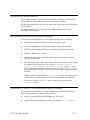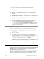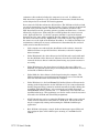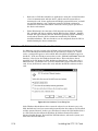
1
®
LONWORKS
PCC-10 PC Card
User’s Guide
Version 2
®
Corporation
078-0155-01B
No part of this publication may be reproduced, stored in a retrieval
system, or transmitted, in any form or by any means, electronic,
mechanical, photocopying, recording, or otherwise, without the prior
written permission of Echelon Corporation.
Echelon, LON, LONWORKS, LonBuilder, NodeBuilder, LonTalk,
LonManager, 3120, 3150, Neuron, the Echelon logo, the LONMARK logo,
and LONMARK are trademarks of Echelon Corporation registered in the
United States and other countries. Other names may be trademarks of
their respective companies.
Neuron Chips, PCC-10 products, and other OEM Products were not
designed for use in equipment or systems which involve danger to
human health or safety or a risk of property damage, and Echelon
assumes no responsibility or liability for use of the Neuron Chips or Power
Line products in such applications.
Parts manufactured by vendors other than Echelon and referenced in
this document have been described for illustrative purposes only and
may not have been tested by Echelon. It is the responsibility of the
customer to determine the suitability of these parts for each application.
ECHELON MAKES AND YOU RECEIVE NO WARRANTIES OR CONDITIONS,
EXPRESS, IMPLIED, STATUTORY OR IN ANY COMMUNICATION WITH YOU,
AND ECHELON SPECIFICALLY DISCLAIMS ANY IMPLIED WARRANTY OF
MERCHANTABILITY OR FITNESS FOR A PARTICULAR PURPOSE.
Printed in the United States of America.
Copyright ©1996, 1997 by Echelon Corporation.
Echelon Corporation
4015 Miranda Avenue
Palo Alto, CA 94304, USA
Contents
1
PCC-10 Introduction
Introduction
Audience
Content
Related Documentation
2
Installing the PCC-10 Card
PCC-10 Card Software Installation
Windows 95® Software Installation Procedure
Windows 3.1 and 3.11 Software Installation Procedure
Microsoft® DOS® Software Installation Procedure
Real-Mode DOS Driver
Configuring the PC for Maximum Performance Under DOS
Conventional Memory
LDVPCC10.INI File Description
Software Installation Results
Windows 95 Software Removal Procedure
Windows 3.1 and 3.11 Software Removal Procedure
DOS Software Removal Procedure
PCC-10 Card Hardware Installation
Windows 95 PCC-10 Card Hardware Revisions
Cancel
Do not install a driver 2-15
Driver from disk...
Select from a list...
Troubleshooting
System Resources
Windows 95
DOS, Windows 3.1 and 3.11
Windows 3.1x Only
Common Resource Problems
Software Compatibility
Device Name Aliasing under Windows 3.1x
and Windows 95
Device Name Aliasing under DOS
LonManager Protocol Analyzer Compatibility
LonManager LonMaker Installation Tool Compatibility
PCLTA-10 Compatibility
WLDV Versions
PCC-10 User’s Guide
1-1
1-2
1-4
1-4
1-4
2-1
2-2
2-3
2-5
2-6
2-7
2-9
2-9
2-9
2-11
2-11
2-11
2-12
2-12
2-14
2-15
2-15
2-15
2-15
2-16
2-16
2-17
2-17
2-18
2-19
2-19
2-20
2-20
2-20
2-20
2-20
iii
3
Configuring and Testing the PCC-10 Card Under
Windows
PCC-10 Configurations
PCC-10 Initialization
Device Specific Settings
Device Selected
Automatic Flush Cancel
NI Application
Transceiver...
Diagnostics
General Settings
System Image Path
Layer2 and Layer6 Buffering
Enable PC Card Reset
PCC-10 Diagnostics
Driver Status
Diagnostic Commands
Test
Comm
Service
Restart
Reset
4
Electrical Interface
Network Port
PC Card Connector
Free Topology Network Connection
5
References
Reference Documentation
Appendix A External Power Line Transceivers
Electrical Interface to the PCC-10 Network Port
PCC-10 External Power Line Transceiver Connection
PL-20 Network Connection
Appendix B Regulatory Information
FCC Information
Industry Canada Statement
iv
3-1
3-2
3-3
3-3
3-3
3-3
3-4
3-4
3-5
3-5
3-5
3-5
3-6
3-6
3-7
3-8
3-8
3-8
3-9
3-9
3-9
4-1
4-2
4-5
4-5
5-1
5-2
A-1
A-2
A-2
A-2
B-1
B-2
B-2
Echelon
1
PCC-10 Introduction
This guide describes the mechanical characteristics and the
hardware and software driver installation for the PCC-10 Network
®
Adapter and the LonManager PCC-10 Protocol Analyzer card.
Except where noted, the term “PCC-10 card” used in this guide refers
to both cards.
The PCC-10 Network Adapter is a high-performance interface that is
ideal for building portable installation, maintenance, monitoring and
control tools. Its compact form-factor and integral FT-10 free
topology transceiver make it well suited for use by installation and
service personnel of industrial automation, building controls,
entertainment/lighting systems, and telecommunication systems.
The PCC-10 Network Adapter provides both network interface
functionality (for use with LonManager API based tools) and network
services interface (NSI) functionality (for use with LNS-compliant
tools). It can be used with any laptop, palmtop, or embedded PC with
a Type II PC Card (formerly PCMCIA) slot and a compatible
operating system.
The LonManager PCC-10 Protocol Analyzer provides LONWORKS
manufacturers, system integrators, and end-users with a rich set of
Microsoft Windows-based tools and two PCC-10 cards for observing,
analyzing, and diagnosing the behavior of installed LONWORKS
networks. In addition to providing the network analysis
PCC-10 User’s Guide
1-1
functionality, the PCC-10 cards included with the protocol analyzer
also provide all the functionality of the PCC-10 Network Adapter.
1-2
Introduction
Introduction
The PCC-10 card provides any host processor equipped with a Type II PC Card
interface and compatible operating system, with access to a LONWORKS network.
It measures 54.0mmW x 85.6mmL x 5.0mmH (2.126" x 3.370" x 0.196"). A
software-based control panel, and software drivers for the Microsoft DOS, Windows
95, 3.1, and 3.11 operating systems are available through purchase of the
Connectivity Starter Kit (model number 58030-01). The control panel provides a
convenient means of setting and modifying installation parameters, as well as
displaying error messages.
The PCC-10 card operates at 10MHz and includes an integral free topology
transceiver for use with an FT-10 channel (free topology and link power). The
internal transceiver permits a user to connect directly to this popular twisted-pair
channel without the need for an external transceiver, minimizing both equipment
cost and set-up time.
Single-ended and special-purpose mode communication ports are available via a
15-pin connector. Access to LONWORKS bus-style, TP/XF twisted pair networks is
accomplished through external transceiver assemblies (referred to as “pods”). The
PCC-10 card can also be used with power line, RF, coaxial cable, IR, and fiber optic
transceivers, and current-limited +5VDC power is supplied for powering the
external pods.
A variety of cable assemblies for different applications are available from Echelon
including a 2-wire cable with an XLR connector, a 2-wire cable with flying leads,
and a 14-wire cable.
Firmware for the PCC-10 card is downloaded from the host. This allows the card to
be updated as new versions of the software and firmware are released, without
modifying or physically accessing the PCC-10 card. This feature extends the useful
service life of the card, and minimizes the cost and time associated with software
and firmware updates.
To simplify card operation, the user can select the language in which most error
messages will be presented. The desired language is specified at installation time.
PCC-10 User’s Guide
1-3
!
• Avoid bending or squeezing the PCC-10 card.
• Do not immerse the PCC-10 card in liquid of any type, and
clean only with a soft, dry, anti-static cloth.
• Do not insert foreign objects into the connectors and avoid
exposure to substances that may contaminate the electrical
contacts.
• Always apply pressure to the release pins on the Hirose
connector when attempting to disconnect a network cable.
Failure to do so may cause damage to the PCC-10 card’s
network port and/or the Hirose connector.
1-4
Introduction
Audience
This manual is intended for developers and end users of LONWORKS systems using
the PCC-10 card.
Content
This manual provides an overview of the PCC-10 card and software, and includes
installation details and configuration options. Electrical specifications for the
network port of the card and related cable assemblies also are included.
This document has a list of references in Chapter 5. Whenever a reference
document is addressed, a superscript number corresponding to the reference has
been placed in the text, i.e., FTT-10 User's Guide1. Whenever a specific chapter or
section within a reference has been referred to, the reference is enclosed in brackets
and the chapter is addressed by number, i.e., Reference [1], Chapter 8.
Related Documentation
The following Echelon publications are suggested for additional information:
•
The on-line version of the LONWORKS PCC-10 User’s Guide is a Windows 95 or
Windows 3.1 Help file. It is placed on the computer’s hard drive by the
PCC-10 Installation Software. The help file can be accessed via the PCC-10
LONWORKS Control Panel (also installed by the PCC-10 Installation Software)
or it can be accessed by opening LONPCC10.HLP in the Windows Help directory
(default: C:\WINDOWS\HELP). This guide offers additional, last-minute
updates but does not replace this manual. The DOS version of the PCC-10
Card Installation Software contains a README.TXT file in place of a help file.
•
LONWORKS FTT-10 Free Topology Transceiver User’s Guide (078-0114-01)
•
LONWORKS FTT-10A Free Topology Transceiver User’s Guide (078-0156-01)
•
LonManager Protocol Analyzer User’s Guide (078-0121-01)
•
LonManager LonMaker Installation Tool User’s Guide (078-0023-01)
PCC-10 User’s Guide
1-5
2
Installing the PCC-10 Card
This chapter describes the procedures for installing the PCC-10 card
software in a PC or embedded host with a compatible operating
system.
PCC-10 User's Guide
2-1
PCC-10 Card Software Installation
!
Installation of the PCC-10 software must precede insertion of
a PCC-10 card into a PC Card (PCMCIA) slot.
Failure to install the software before inserting the card will
render the card unusable until the software is removed, and
then reinstalled.
The six steps of the installation process are as follows:
1.
Install Windows PCMCIA driver if not currently installed. A Windows
PCMCIA driver must be installed prior to PCC-10 card installation. Under
Windows 95, the PC Card driver is installed automatically when the PC
Card drive is installed. (If this driver is not present, please consult the
Windows 95 documentation.) Under Microsoft DOS, Windows 3.1 and
Windows 3.11, the PC Card driver must be installed manually. If the
driver has not been installed, please consult the PC Card drive
manufacturer’s documentation and install the PC Card driver before
continuing.
2.
If you have purchased the LonManager PCC-10 Protocol Analyzer, install
the protocol analyzer applications following the instructions provided in
the LonManager Protocol Analyzer User’s Guide3. Note that you cannot
use the LonManager ISA Protocol Analyzer card and a PCC-10 card in the
same PC.
3.
Install the PCC-10 driver software as described below.
4.
Insert the PCC-10 card, as described later in this chapter.
5.
Attach cable/pod.
6.
Install the LONWORKS Network Services (LNS) software, if used.
Note: If the LonManager Protocol Analyzer software is installed after installing
the PCC-10 card software, the PCC-10 card software must be re-installed.
2-2
Installing the PCC-10 Card
Windows 95 Software Installation Procedure
Prior to installation, ensure that the computer is running the Windows 95
Operating System. The PCC-10 software cannot be installed from DOS, or a DOS
shell.
1.
Close all open programs.
2.
Insert the installation diskette into the PC.
3.
Click the Start button on the Windows 95 task bar and select the run
command.
4.
When prompted for a program name, enter the following:
a:\SETUP.EXE
If necessary, replace a: with the drive letter which corresponds to the drive
containing the PCC-10 installation diskette.
5.
When prompted with a list of languages, click on the desired language. A
checkmark will appear to the left of the language to be installed.
6.
When prompted for a destination directory, enter the desired installation
directory. By default this directory is c:\lonworks, unless previous
LONWORKS products have been installed and registered a different path in
the Windows Registry. The path may be modified using the Browse button;
however, if a directory other than c:\lonworks is chosen, the PCC-10 images
path will have to be specified to enable use of the PCC-10 card. This is
accomplished during PCC-10 Configuration. See Chapter 3, Configuring and
Testing the PCC-10 Card.
7.
When the 16-bit Application Support prompt appears, select “Yes” to enable
the use of 16-bit applications with the PCC-10 card. This causes the
installation program to add references to the DOS CONFIG.SYS file for the
‘stub’ device drivers named PCCLON1 and PCCLON2. This allows existing 16-bit
applications, such as the LonManager Protocol Analyzer’s channel interface
maker tool, to recognize these device names and use the PCC-10 card as a
network interface. If the PC has more than two PC Card slots, two additional
stub device drivers can be created manually. To do so, add the following lines
to the CONFIG.SYS file:
DEVICE=C:\LONWORKS\BIN\LDVSTUB.SYS /D:PCCLON3
DEVICE=C:\LONWORKS\BIN\LDVSTUB.SYS /D:PCCLON4
There is a limit of four (4) PCC-10 cards on a single PC.
To access the PCC-10 card, the “PCCLONn” network interface naming
convention must be used, rather than the “LONn” naming convention used with
other Echelon products. Use of this naming convention will direct the software
PCC-10 User's Guide
2-3
to use the PCC-10 card device driver under Windows rather than attempting
to access the device under DOS.
Once this driver is installed and active, existing 16-bit Windows applications
can access the PCC-10 card using the ldv_open(), ldv_close(),
ldv_read(), and ldv_write() functions provided by the WLDV.DLL file.
The installation software installs a new WLDV.DLL file, replacing any preexisting versions of the file. The updated WLDV.DLL is fully backwardcompatible with previous versions.
8.
If the installation software discovers the SYSTEM.INI entry that loads the
ISA-bus driver, ECHLMPA.386, it will comment out the entry and display the
message, “SETUP has modified your SYSTEM.INI file by removing the
following entry: device=echlmpa.386.” It is not possible to use the ISA-bus
protocol analyzer card and the PCC-10 card on the same PC.
9.
The installation software for the Windows 95 version will issue a prompt to
add a DOS virtual-mode device driver file named LDVVDD.SYS to the DOS
CONFIG.SYS file to support DOS applications calling LON1. This will allow
DOS applications to be used in a Windows 95 DOS shell/window. For more
information see Virtual-Mode DOS Driver later in this chapter. The following
line is added to the CONFIG.SYS file:
DEVICE=C:\LONWORKS\BIN\LDVVDD.SYS /D1
10. Installation is complete. At the prompt to restart the computer, remove the
PCC-10 installation diskette and restart the computer. Note that Windows
will not recognize the PCC-10 card until the computer is restarted.
2-4
Installing the PCC-10 Card
!
Windows 95 Warning
Some Windows 95 computer systems come equipped with hardware (such
as CDROM drives) which use their own card and socket services. These
services replace those provided by Windows 95, and may contain
incompatibilities that prevent the PCC-10 card from functioning.
TM
One example is SystemSoft’s CardWorks PCMCIA Drivers, which are
TM
packaged with the Axonix ProMedia Portable CDROM Drive. To allow
the PCC-10 card to operate with these drivers, some of its services must be
disabled by commenting-out the lines in the PC’s CONFIG.SYS file which
contain the following instructions:
C:\CARDWORK\SSTOPIC.EXE,
C:\CARDWORK\MTAA.EXE,
C:\CARDWORK\MTI1.EXE,
C:\CARDWORK\MTATM.EXE,
C:\CARDWORK\MTSRAM.EXE,
C:\CARDWORK\FTL.EXE,
C:\CARDWORK\AXONIXXR.SYS
C:\CARDWORK\ATADRV.EXE,
C:\CARDWORK\MTAB.EXE,
C:\CARDWORK\MTI2P.EXE,
C:\CARDWORK\MTHB2.EXE,
C:\CARDWORK\MTDDRV.EXE,
C:\CARDWORK\CARDID.EXE,
Windows 3.1 and 3.11 Software Installation Procedure
Prior to installation, ensure that the computer is running the Windows 3.1 or 3.11
Operating System (hereafter referred to as Win3.1x). The PCC-10 software cannot
be installed from DOS or a DOS window.
1.
Close all open programs.
2.
Insert the installation diskette into the PC.
3.
Within Program Manager, choose the Run command from the File menu.
4.
When prompted for a program name, enter the command:
a:\SETUP.EXE
If necessary, replace a: with the drive letter which corresponds to the drive
containing the PCC-10 installation diskette.
5.
When prompted with a list of languages, click on the desired language. A
checkmark will appear to the left of the language to be installed.
6.
When prompted for a destination directory, enter the desired installation
directory. By default this directory is c:\lonworks, unless previous
LONWORKS products have been installed and registered a different path in
the ECHELON.INI file. This path may be modified using the Browse button;
PCC-10 User's Guide
2-5
however, if a directory other than c:\lonworks is chosen, the PCC-10 images
path will have to be specified to enable use of the PCC-10 card. This is
accomplished during PCC-10 Configuration. See Chapter 3, Configuring the
PCC-10 Card.
7.
To access the PCC-10 card, the “PCCLONn” network interface naming
convention must be used, rather than the “LONn” naming convention used with
other Echelon products. Use of this convention will direct the software to use
the PCC-10 card device driver under Windows rather than attempting to
access the device under DOS.
The installation software will issue a prompt to add references to the DOS
CONFIG.SYS file to support ‘stub’ device drivers named PCCLON1 and
PCCLON2. This will allow 16-bit Windows applications to recognize these
device names and use the PCC-10 card as a network interface. If the PC has
more than two PC Card slots, two additional stub device drivers can be created
manually. To do so, add the following lines to the CONFIG.SYS file:
DEVICE=C:\LONWORKS\BIN\LDVSTUB.SYS /D:PCCLON3
DEVICE=C:\LONWORKS\BIN\LDVSTUB.SYS /D:PCCLON4
There is a limit of four (4) PCC-10 cards on a single PC.
Once this driver is installed and active, applications can access the PCC-10
card using the 16-bit API for Windows.
The installation software installs a new WLDV.DLL file, replacing any preexisting versions of the file. The updated WLDV.DLL is fully backwardcompatible with previous versions.
8.
If the installation software discovers the SYSTEM.INI entry that loads the
ISA-bus driver, ECHLMPA.386, it will comment out the entry and display the
message, “SETUP has modified your SYSTEM.INI file by removing the
following entry: device=echlmpa.386.” It is not possible to use the ISA-bus
protocol analyzer card and the PCC-10 card on the same PC.
9.
Installation is complete. At the prompt to restart the computer, remove the
PCC-10 installation diskette and restart the computer. Note that Windows
will not recognize the PCC-10 card until the computer is restarted.
The card and socket services of the following vendors have been tested with
standard PCs and the PCC-10 card: American Megatrends’ AMICARDZ,
Award Software’s CardWare, IBM’s PlayAtWill, Phoenix Technology’s PCM3+,
and SystemSoft’s CardSoft.
Microsoft DOS Software Installation Procedure
There are two versions of the DOS driver—both of which will allow the PCC-10
Card to be used with DOS-based products, like the LonMaker™ Installation Tool.
This driver does not support Windows applications, like the LonManager Protocol
Analyzer. One version will allow the PCC-10 Card to be used with DOS-based
2-6
Installing the PCC-10 Card
products by using the Windows 3.1 or Windows 3.11 operating systems with proper
Windows Card & Socket Services, or by using the Windows 95 operating system
with Microsoft-provided Card & Socket Services. The Windows 3.1x and Windows
95 PCC-10 card installation software will prompt the installer to automatically add
this version of the DOS driver. The driver is small in size, and allows a DOS
session under Windows to have access to the PCC-10 through the device driver
running as part of Windows. The driver will not function unless a Windows session
is running, and the PCC-10 device driver is installed.
The following line will be added to the CONFIG.SYS file:
DEVICE=<directory of file>\LDVVDD.SYS (/Dn or /Vxxxx)
/Dn
where (n) is 1-4. This defines LON1-LON4, and corresponds to devices
1-4 as determined by the PCC-10 Card device driver under Windows.
/Vxxxx
where (xxxx) describes the VxD ID, in hexadecimal. This is not required
for the PCC-10 Card device driver since the default setting will work. To
use the services of the PCLTA/PCNSI Windows 95 device driver,
ECHPCLTA.VXD, you must use /V3474 instead of /D1.
The following is an example of the line that would be added to the CONFIG.SYS
file:
DEVICE=C:\LONWORKS\BIN\LDVVDD.SYS /D1
The second version of the driver, known as the Real-Mode DOS Driver, is for use
with Microsoft DOS where no Windows operating system is being used.
Real-Mode DOS Driver
Real-Mode DOS support for the PCC-10 Card (tested on DOS 6.22) consists of a single
device driver named LDVPCC10.SYS which can control up to four (4) cards, third
party DOS-level PCMCIA Card and Socket services provided by the manufacturer of
your PCMCIA card slot, and associated files. These files consist of an INI file and the
PCC-10 Card system images.
Follow these steps to install the real-mode DOS driver:
!
To use a PC Card under DOS (without using the Windows Card
& Socket Services), the PC must have “DEVICE=” references to
DOS-level Card & Socket Services in the CONFIG.SYS file, and
appropriate card services drivers loaded on the PC.
These “DEVICE=” references to card services must precede the
references to the PCC-10 Card driver to function.
PCC-10 User's Guide
2-7
1.
Close all open programs, and run installation from DOS or a DOS box within
Windows 3.1, Windows 3.11, or Windows 95.
2.
Insert the installation diskette into the PC, then enter the following
(substituting the appropriate drive letter for a: if the diskette is not in this
drive):
a:\INSTALL.EXE
3.
After a moment of disk activity, the product name and release number will be
displayed, along with the following message:
Press [ESC] to quit, any other key to continue...
The installation can be aborted at any time by pressing ESC. To continue with
the installation, press any other key.
4.
The next screen provides some basic instructions concerning installation. Press
any key (other than ESC) to continue.
5.
A list of available hard disk drives will be displayed. Use the arrow keys to
select the drive where the PCC-10 Card software should be installed. The
default drive is C. Press ENTER when the proper drive is highlighted. If the
computer does not display blinking options, the highlighted option will be
shown as black writing on a white background.
6.
When prompted for a destination directory, enter the desired installation
directory. By default this directory is \LONWORKS. Press ENTER if this is the
desired directory. If the PCC-10 DOS Device Driver software has already been
installed in this directory, the installation program will confirm overwriting
the existing PCC-10 files in \LONWORKS\BIN.
7.
Pressing a key other than ESC will cause the appropriate files to be copied to
the specified directory.
8.
Press “Y” when prompted to verify:
May I create/modify your CONFIG.SYS file if needed (Y/N)?
The modification consists of adding the line:
DEVICE=C:\LONWORKS\BIN\LDVPCC10.SYS C:\LONWORKS\BIN\LDVPCC10.INI
Press “Y” to let the installation software automatically update the
CONFIG.SYS file. The original CONFIG.SYS file will be renamed
CONFIG.BAK.
The name LDVPCC10.INI is arbitrary. The installation process will create
this file as a default. The CONFIG.SYS file can be modified later to load the
device high if needed, by using “DEVICEHIGH=” rather than “DEVICE=”.
9.
2-8
The added line will be displayed. Press any key other than ESC to continue.
Installing the PCC-10 Card
10. “<<INSTALLATION COMPLETE>>” will be shown followed by several options
for modifying the default settings of the PCC-10 DOS Device Driver. The
location of the README.TXT file C:\LONWORKS\IMAGES\PCC10\README.TXT
will also be shown. Press any key other than ESC to continue.
11. If the installation program did not automatically update the CONFIG.SYS file,
it should be done manually at this time.
12. Installation is complete. Remove the PCC-10 installation diskette and restart
the computer. Note that Windows will not recognize the PCC-10 card until the
computer is restarted.
Configuring the PC for Maximum Performance
Under DOS
This section describes setting up the PC to obtain the maximum performance from
the DOS driver. The performance of the PCC-10 DOS Device Driver software can
be greatly enhanced by correctly configuring the PC’s conventional memory.
Many of the changes described in this section require changes to your CONFIG.SYS
or AUTOEXEC.BAT files. Be sure to reboot the PC after making these changes so
that the new settings can take effect.
Conventional Memory
The PCC-10 DOS Device Driver requires conventional memory equal to the actual
size of the device driver plus 260 bytes per input or output buffer set in the
LDVPCC10.INI file for all device handles (LON1, LON2, etc.):
Required Memory = Driver Size + (260 * (Total Input Buffers + Total Output
Buffers))
The amount of conventional memory available is determined by the total
conventional memory of the PC, the version of DOS, the DOS configuration, and
memory-resident drivers, and programs.
Conventional memory may be increased by using a memory manager such as
Microsoft MemMaker or the Quarterdeck Expanded Memory Manager (QEMM386), or by loading DOS into High or Extended Memory using EMM386.SYS with
DOS 6.2 or later. Extended memory is the memory beyond the first 1 MByte of
address space in the PC. Consult the DOS documentation provided with the
computer for details.
LDVPCC10.INI File Description
The LDVPCC10.INI file is an ASCII text file which contains sections defining up to
four (4) PCC-10 Card devices. Each section name defines the device name,
typically LONn, but can be any eight (8) -character device name. A section name is
a word enclosed in brackets, i.e., [LON1]. A new word within brackets defines a
new section.
PCC-10 User's Guide
2-9
Within each section the following entries should exist:
ImagePath=filepath
where filepath is the full file pathname for the Neuron Chip Binary Image
(NBI), or system image, to be loaded for this device. Since this driver does
not support the LonManager Protocol Analyzer this filepath would point to
either a Layer7 MIP system image or an NSI MIP system image, like
“PCC10L7.NBI” or “NSIPCC.NBI”.
OutputBuffers=n
where n describes the number of downlink output buffers that the device
driver should use for this device. This value should be between 2 and 99.
InputBuffers=n
where n describes the number of uplink input buffers that the device driver
should use for this device. This value should be between 2 and 99.
FlushCancel=n
where n describes whether the device driver will automatically force the
network interface (for the selected PCC-10 card) to leave the post-reset flush
state whenever it is reset. The post-reset flush state prevents any inbound or
outbound network traffic following a reset. This value should be ‘1’ to
automatically leave the flush state, or ‘0’ to leave it up to the client
application to manage this state.
Example:
[LON1]
ImagePath=C:\lonworks\images\pcc10\pcc10l7.nbi
OutputBuffers=6
InputBuffers=6
FlushCancel=1
There is no utility to modify or maintain the INI file. Since it is a simple text file it
can be modified with any text editor.
2-10
Installing the PCC-10 Card
Software Installation Results
The installation software for the PCC-10 Card loads a selection of new files and
updated Echelon files to different locations on the PC’s hard drive.
For Windows installations, the function and location of the files can be found in the
on-line help file.
For DOS installations, see the section entitled MS-DOS Software Removal
Procedure in this manual.
Windows 95 Software Removal Procedure
To remove the PCC-10 software, use the Uninstall control panel, as follows:
1.
Close the “LonWorks® Plug ‘n Play” control panel if it is open.
2.
Choose the Add/Remove Programs icon from the Control Panel folder.
3.
Select “LonWorks® PCC-10” from the list under the Install/Uninstall tab.
4.
Click the “Add/Remove...” button.
5.
Confirm file deletion at the prompt. Most of the PCC-10 software will be
removed automatically.
6.
The “LonWorks® Plug ‘n Play” control panel must be removed manually. Close
the Control Panel folder if it is open. Rename C:\Windows\System\
Pcc10cfg.cpl to C:\Windows\System\Pcc10cfg.cpx, (where C: is the
drive containing the Windows folder) then remove the file Pcc10cfg.cpx by
placing it in the Recycle Bin. It is not nessessary to empty the Recycle Bin at
this time.
Windows will not allow deletion of Pcc10cfg.cpl because it is registered as a
control panel. Renaming the file circumvents this Windows 95 restriction.
7.
If necessary, edit the CONFIG.SYS file to remove any references to the
LDVSTUB.SYS driver.
Windows 3.1 and 3.11 Software Removal Procedure
To remove the PCC-10 software, use the File Manager or DOS command line to
delete the PCC-10 software from the PC, as follows:
1.
Close the “LonWorks® PCC-10 Card Manager” if it is open.
2.
Open the directory in which the software was installed, i.e., c:\LONWORKS.
PCC-10 User's Guide
2-11
3.
Within the enclosed \BIN subdirectory, delete the following files:
LDVSTUB.SYS
LONCSM.EXE
LONPCC10.386
4.
Within the \IMAGES subdirectory, remove the \PCC10 directory and its
contents.
5.
At the root drive level (default: C:\ ), edit the CONFIG.SYS file to remove any
references to the LDVSTUB.SYS driver.
6.
From within the \WINDOWS directory, edit the SYSTEM.INI file to remove any
references to LONPCC10.386.
7.
If no other LONWORKS-based products are present on the computer, the
WLDV.DLL file may be deleted from the Windows System (default:
c:\windows) directory. If other LONWORKS-based products are present, the
WLDV.DLL file may be required to use those products, and therefore should
remain in the Windows directory.
DOS Software Removal Procedure
To remove the PCC-10 software, open the CONFIG.SYS file with a text editor.
1.
Remove any “DEVICE=” references to LDVVDD.SYS, LDVPCC10.SYS, and
LDVPCC10.INI.
2.
Reboot the computer.
3.
If no Windows version of the PCC-10 Device Driver is installed on the
computer, then delete the \PCC10 directory and its contents from the \IMAGES
directory in the main directory in which the PCC-10 was installed, i.e.,
DELTREE \LONWORKS\IMAGES\PCC10
[RETURN]
If a Windows version of the PCC-10 Device Driver does exist, then remove the
README.TXT file from the \IMAGES\PCC10 directory.
4.
Delete LDVVDD.SYS, LDVPCC10.SYS, and LDVPCC10.INI from the \BIN
directory (i.e., C:\LONWORKS\BIN).
PCC-10 Card Hardware Installation
If the software has not been installed, please read the earlier section titled PCC-10
Software Installation. The Windows operating system will not recognize the
PCC-10 card without the software installed.
The PCC-10 card conforms to the Personal Computer Memory Card International
Association’s (PCMCIA) standard for hot plug-in. The PCC-10 card will not be
harmed if it is inserted into, or removed from, a PC Card (PCMCIA) slot which
2-12
Installing the PCC-10 Card
conforms to this standard, whether the computer is on or off. In addition, the
PCC-10 card is recognized as a UL (Underwriter’s Laboratories) Listed Accessory
and is designed to be used with UL Listed equipment.
Do not force the PCC-10 card into the PC Card slot. The PCC-10 card is keyed and
can only be inserted one way into the PC Card slot. Figure 4.4 shows the 68-pin PC
Card side of the PCC-10 card. In a Windows 95 environment, insertion of the
PCC-10 card will cause the operating system to produce two brief tones: a low tone
followed by a higher tone. Extracting the card will produce the tones in reverse
order: high and then low. If a device’s property window is open in the System
Control Panel, the tones will be produced after the window is closed to confirm that
the device is inserted correctly. Additionally, a PC Card icon may also appear in
the status area to the right of the Windows 95 taskbar. In a DOS or Windows 3.1x
environment, notification of correct card insertion is determined by the card and
socket services installed on the PC.
•
If the computer was rebooted after installation of the software, insert the
PCC-10 card into an open PC Card slot. Otherwise, reboot the computer
before insertion.
•
Under Windows 95, the device driver for the PCC-10 card is not loaded until
the first PCC-10 card is discovered. Likewise, when the last PCC-10 card is
removed, the device driver is unloaded, thus freeing any system resources it
was using.
•
Under Windows 3.1x, the device driver is loaded at the start of Win3.1x.
Similarly, the PCC-10 system images and configuration information are read
and stored at Windows boot-time.
•
Under DOS, the device driver is loaded upon booting the computer. The
PCC-10 system images and configuration information are read and stored
when the PCC-10 Card is inserted into the computer.
•
Under Windows 3.1x, the LONWORKS PCC-10 Card Services Client must be
running in the background to use the PCC-10 card. If it is removed from the
StartUp Program Group, it must be invoked manually by double-clicking the
icon titled, “PCC-10 CS Client,” or by running the executable file named
LONCSM.EXE, which is found in the \bin subdirectory of the PCC-10 card
installation directory. This application can also be used to view the resources
allocated to the PCC-10 and control IRQ assignments.
•
A PCC-10 card may not be recognized in Windows 3.1x under some card and
socket services if insertion occurs while in a DOS shell. The inserted card
may be reacquired by exiting and restarting the PCC-10 Card Manager
application.
•
Each PCC-10 card requires a single, dedicated interrupt request (IRQ) and
four contiguous bytes of I/O address space starting on a modul0-4 based
address.
PCC-10 User's Guide
2-13
•
Removal of a PCC-10 card while an application is using the card will result in
a loss of communication with the device, which cannot be restored by reinserting the card. Some applications will display unusual behavior, and will
not properly function. Any application using the PCC-10 card must be
restarted if a PCC-10 card has been removed to ensure proper operation of
the device and software.
•
Under Windows 95, the first time a PCC-10 card is inserted into a running
PC, a window will appear with the words “Echelon Corp.-PCC-10.” Another
window will appear stating that the Windows operating system is building a
new database from the device information installed by the PCC-10
installation diskette. The new hardware can be configured when the PC has
finished writing the device information.
Windows 95 PCC-10 Card Hardware Revisions
If a different, or newer, version of the PCC-10 card is inserted into the PC Card
slot, a New Hardware Found window may be presented (see figure 2.1). In this
event, a prompt will appear to select which driver should be installed for the new
®
hardware. If the new hardware states that it is the “PCC-10 LONWORKS Network
Interface,” then choose the Windows default driver. This is the driver that is
installed on the PC during the PCC-10 Software Installation. If the driver has a
different name, you must be sure you have installed the proper software for that
card. If not, click Cancel, remove the card, and then install the software for that
card.
Figure 2.1 New Hardware Found Dialog Box
If the Windows default driver choice cannot be selected (or is shown in gray), the
PCC-10 Card may have been erroneously inserted before the software was installed
and the system rebooted. In this case, click Cancel, remove the PCC-10 Card if it is
in a PC Card slot, then follow the Windows 95 Software Removal Procedure
discussed in this chapter. Re-install the PCC-10 software, reboot the system, and
then insert the PCC-10 Card.
2-14
Installing the PCC-10 Card
If cancel or an option other than Windows default driver is chosen, follow the
instructions indicated for that selection below:
Cancel
If the Cancel button is accidentally selected, remove the PCC-10 card and re-insert
it. This action will cause the New Hardware Found window to be displayed again.
Choose the Windows default driver.
Do not install a driver
If this option is chosen, the PCC-10 software must be re-installed to use the PCC-10
card. This screen will only be presented once.
Driver from disk…
Do not select this option. If this option is selected inadvertently, a prompt will ask
for a diskette containing the driver. Since the PCC-10 software installation
diskette does not include the driver in a readable form, no driver will be found. In
this case, cancel the request, remove the PCC-10 card, and re-insert it. This will
cause the New Hardware Found window to be displayed again. Choose the
Windows default driver.
Select from a list…
Do not select this option. If this option is selected inadvertently, a list of drivers is
displayed which does not contain the required driver. In this event, cancel the
request, remove the PCC-10 card, and re-insert it. This action will cause the New
Hardware Found window to be displayed again. Choose the Windows default
driver.
Troubleshooting
As a “plug and play” type device, the PCC-10 PC Card should operate as desired
following completion of the installation process. If the PCC-10 card does not
function correctly, the most likely causes are system resource constraints or
software incompatibilities. These problems are described in detail in the following
sections.
Windows 95 has some limitations regarding Card & Socket Services. Intel, Vadem,
IBM DataBook, Compaq, Maxtor, Cirrus are among the socket controller
companies that are supported by Windows 95: not all controllers from all
manufacturers are supported by Windows 95.
PCC-10 User's Guide
2-15
System Resources
Each PCC-10 card requires four contiguous bytes of I/O address space starting on a
modulo-4 based address (i.e., an address evenly divisible by 4). A dedicated
interrupt request (IRQ) is also required for each PCC-10 card used.
Windows 95
I/O resource problems are rare under Windows 95 for the PCC-10 card since the
card can handle a wide range of I/O settings. However, IRQ resource problems
may occur more often in “multimedia” computers which may have very few spare
IRQs. The Windows 95 operating system handles most allocations of IRQs, but
there are some instances where the operating system cannot properly allocate
interrupt requests.
When the Windows 95 Device Manager does not locate a free IRQ for a newly
inserted PCC-10 card, it will not assign the card an IRQ. As a result, there may be
no indication to the user that a problem has occurred, since no true resource
“conflict” has occurred. This is a consequence of the PCC-10 card’s ability to be
assigned any of the system’s 16 IRQs.
IRQ usage in the system can be determined by opening the System icon in the
Control Panels window. The tab labeled “Device Manager” allows viewing of
devices by type or connection.
The PCC-10 LONWORKS Network Interface device icon is found under the
“LonWorks Interface” device type, or under the “PCIC or compatible PCMCIA
controller” connection. If there is a problem with the PCC-10 card, there will be a
red circle with an exclamation point next to its icon.
The PCMCIA socket device type may contain a “PCIC or compatible PCMCIA
controller” device that has a different IRQ than the “PCC-10 LONWORKS Network
Interface” device. This occurs because the PCMCIA controller has its own IRQ for
detecting card insertions and removals.
IRQ resource problems may generally be resolved by disabling another device in
the system. More information can be found in the Hardware Conflict
troubleshooting portion of the Windows 95 on-line help file.
Access the hardware conflict troubleshooter through the procedure outlined below:
1. Open the Windows 95 on-line help by clicking the Windows Start button and
selecting “Help”.
2. In the Help Topics window, choose the Contents tab, or from another Help
window, choose the Contents button.
3. Double click the Troubleshooting topic, and then select the help topic, “If you
have a hardware conflict,” or “If you have trouble using a PC card
(PCMCIA).”
Extensive trouble-shooting documentation can be found in the Microsoft Windows
95 Resource Kit Help File. This help file is part of the Windows 95 Resource Kit,
which is available from Microsoft.
2-16
Installing the PCC-10 Card
If a DOS real-mode driver is in use, other than the PCC-10 Card DOS driver, for a
specific device which is installed in the PC, Windows 95 may not know about that
device’s resource requirements. Unlike Windows driver conflicts, this problem is
difficult to diagnose.
There are rare I/O conflict situations of which the Device Manager may be unaware.
Such a conflict may occur when an I/O resource is not properly specified for a device,
and a new PC Card driver overlays onto the true I/O space of that device. In the
event of such a conflict, it may become necessary to manually reserve I/O or IRQ
resources using the Device Manager. This process is described in the Windows 95 online help.
If a device resource requirement is “hardwired” into the PC, i.e., configured by a
jumper or not modifiable from the system BIOS, then there is little that the Windows
95 operating system can do to free the resources.
DOS, Windows 3.1 and 3.11
Under DOS and Windows 3.1x, the management of resources (IRQs, I/O ports, and
DMA) in a PC Card-equipped computer is the responsibility of the card services
driver and its utilities. These must be installed and operating prior to use of the
PCC-10 card. The card services are initialized at boot-up with information about the
basic, non-configurable system resource requirements. Once card services receives
this information, which is typically stored in an initialization file, it may allocate
available resources to PC Cards, as necessary.
It is important that the resource information that is used to initialize card services be
correct. Utilities are usually provided, or are available from the card and socket
services vendor, which can create and modify the resource database. Incorrect
information will allow conflicts when allocating these resources. Consult your
vendor’s card and socket services documentation for further details, or for
information on obtaining the needed utilities.
Windows 3.1x Only
If the card services are misallocating IRQ resources and assigning PCC-10 cards to
IRQs that are already claimed by other devices, the LONWORKS PCC-10 Card
Services Client may be used to correct the problem. Restoring the LONCSM.EXE icon
reveals the LONWORKS PCC-10 Card Manager window (figure 2.2).
PCC-10 User's Guide
2-17
Figure 2.2 LONWORKS PCC-10 Card Services Client
Selecting the Configuration Info menu item under the appropriate socket menu
displays the resources allocated to the PCC-10 card (figure 2.3).
Figure 2.3 Allocated PCC-10 Card Resources
Selecting IRQ under the Resources menu displays the IRQ Resource Control dialog
(figure 2.4). This dialog allows the inclusion or exclusion of IRQs from the card
services IRQ allocation pool. To exclude an IRQ, clear the checkbox next to the
IRQ name. Please note that the IRQ Resource Control settings will only take effect
at card insertion time.
Figure 2.4 IRQ Resource Control Dialog
Common Resource Problems
The following situations produce an additional drain on system resources that may
be hard to manage. Conflicts arising from these situations can generally be
resolved by selectively disabling devices to free up the required resources:
•
2-18
COM ports that may not have a connector, but are consuming resources and
cannot be disabled through the BIOS;
Installing the PCC-10 Card
•
Unused IDE controllers that can not be disabled through the BIOS;
•
Unused/nonexistent PS/2 mouse ports;
•
Sound cards that support both 8-bit and 16-bit compatibility modes,
consuming two IRQs.
An additional problem often associated with sound cards is the improper reporting
of I/O resource usage. This problem may be recognized by examining a device’s I/O
address allocation for strange one-byte assignments since devices typically use
more. For example, if a device’s stated I/O range is 0x201-0x201 but its actual
range is 0x201-0x204, a conflict will occur if the PCC-10 card is assigned an I/O
range of 0x204-0x207. If this problem is suspected, manually move the PCC-10
card’s I/O range to a safer location to prevent I/O overlap.
Software Compatibility
The PCC-10 card software is designed to be compatible with LONWORKS-based
software. However, the following issues may arise when using the PCC-10 card
with some software.
Device Name Aliasing under Windows 3.1x
and Windows 95
The PCC-10 card should operate with most third-party LONWORKS-based
software. However, some 16-bit Windows applications which use the services of
Echelon’s WLDV dynamic link library are limited in the device names that can be
selected. For example, only the names “LON1” through “LON9” may be available,
preventing the use of a PCC-10 card. This problem can be fixed through the use of
device name aliasing. To create a device alias under Windows 3.1x or Windows 95,
follow the instructions below:
1. Open the file named ECHELON.INI, which should reside in the WINDOWS
directory. If this file does not exist, then create one with a text editor.
2. Create a driver alias section in the file, by adding the following line:
[DRIVERALIAS]
3. On the following line, add the driver alias:
aliasname=devicename
where aliasname is the device name accessed by the software, such as
“LON1”, and devicename is the device to be used.
4. Add additional aliases, as necessary.
The following example creates a device alias that routes all service requests for
LON1 to the PCC-10 card PCCLON1.
[DRIVERALIAS]
LON1=PCCLON1
PCC-10 User's Guide
2-19
Device Name Aliasing under DOS
The file, LVDPCC10.INI, contains the device names for the DOS-mode driver. The
installation default name is LON1 since this is the default name for most DOSbased LONWORKS software. The name may be changed by modifying the file in a
text editor.
LonManager Protocol Analyzer Compatibility
The device driver for the PCC-10 card and the driver for the LonManager Protocol
Analyzer ISA-bus card share the same Windows VxD identifier. As a result, both
types of cards cannot run on a PC at the same time. Therefore, the PCC-10 installation software will comment out the SYSTEM.INI entry that loads the ISA-bus
driver.
LonManager LonMaker Installation Tool Compatibility
When running the LonMaker Intallation Tool there may be a message explaining
the need for additional memory to use all the functions within LonMaker. If this
occurs, try to free additional conventional memory.
If an error is displayed stating there is not enough memory to run LonMaker, then
see the installation section for solutions for moving drivers into high memory.
Additionally, if the computer is not used for memory PC Cards, then the PC Card
memory drivers can be removed (CARDSOFT is used as an example):
rem DEVICE=C:\CARDSOFT\MEMDRV.EXE
rem DEVICE=C:\CARDSOFT\MS-FLASH.SYS
PCLTA-10 Compatibility
The LONWORKS plug ‘n play control panel can only support one type of
downloadable-image network adapter at a time. As a result, PCC-10 cards and
PCLTA-10 adapters may not both be used in the same PC.
WLDV Versions
The PCC-10 card should operate with most third-party LONWORKS-based
software. Some third-party manufacturers have the right to redistribute the
WLDV.DLL dynamic link library file with their own software. Older versions of
Echelon’s WLDV.DLL file do not support the PCC-10 card. Remove any instances of
WLDV.DLL from the third-party directories and subdirectories. WLDV.DLL should
exist only in the WINDOWS\SYSTEM directory under Windows 95, or the WINDOWS
directory under Windows 3.1x.
If an older version of the file is inadvertently copied into the WINDOWS\SYSTEM
directory under Windows 95, or the WINDOWS directory under Windows 3.1x, the
PCC-10 card will be unable to operate. Should this occur, reinstall the PCC-10
software to update WLDV.DLL, or download the newest file from Echelon web site at
www.echelon.com.
2-20
Installing the PCC-10 Card
3
Configuring and Testing the
PCC-10 Card under Windows
This chapter explains how to configure and test the PCC-10 card
using the Windows Control Panel installed in Chapter 2.
Details of how to configure the PCC-10 Card for use with the DOS
driver can be found in the Microsoft DOS Software Installation
Procedure section in Chapter 2.
PCC-10 User's Guide
3-1
PCC-10 Configuration
PCC-10 card configuration is accomplished using the LONWORKS PCC-10 control
panel. Open the control panel by selecting the “LonWorks¨ Plug ‘n Play” icon in the
Control Panel folder located in the My Computer folder on the Windows 95
Desktop, or in the Program Manager’s Main folder under Windows 3.1 or 3.11.
There is no Control Panel for the MS-DOS PCC-10 Device Driver. Configuring a
PCC-10 Card for use with the DOS driver must be done after installation. Details
of how to configure the PCC-10 Card for use with the DOS driver can be found in
the Installation section. Testing of the PCC-10 Card can be performed using the
NODEUTIL.EXE utility which is available in the Developers Toolbox at the Echelon
web site at www.echelon.com.
Figure 3.1 Plug ‘n Play Icon and Control Panel for the PCC-10 Card
The LONWORKS PCC-10 control panel is divided into three parts: a device selection
area, a general settings area, and a control section. The device selection area
contains configuration settings and diagnostic controls that are specific to an
individual PCC-10 card and its device driver. The general settings area contains
settings for all PCC-10 cards used with the computer. The control section contains
buttons for accepting or canceling the changes made in the control panel, as well as
a Help button.
3-2
Configuring the PCC-10 Card
PCC-10 Initialization
In most cases, PCC-10 card initialization occurs automatically upon insertion.
Manual initialization will be required following software installation to a directory
other than C:\LONWORKS, or moving of the PCC-10 system images.
To manually initialize the PCC-10 card, verify that the control panel’s System
Image Path entry is correct, then click the Apply button.
An error will be reported if an attempt is made to modify the transceiver type
before the PCC-10 card is initialized. Testing the card with the Diagnostics button,
as suggested by the error message, produces the diagnosis: “Image file not found.”
In this case, return to the control panel’s main dialog box, and manually initialize
the PCC-10 card.
Device Specific Settings
The PCC-10 specific options consist of five separate controls (figure 3.2). These
controls are defined as follows:
Figure 3.2 PCC-10 Specific Controls
Device Selected
This setting controls which PCC-10 card is selected for configuration. The
PCCLON1 and PCCLON2 drivers are installed by the installation software. If
additional drivers have been manually installed, one or both of PCCLON3 and
PCCLON4 will also be available.
Automatic Flush Cancel
This setting controls whether the device driver will automatically force the network
interface (for the selected PCC-10 card) to leave the post-reset flush state whenever
it is reset. The post-reset flush state prevents any inbound or outbound network
traffic following a reset. If this box is not checked, it is up to the client application
to manage this state. If it is checked, the device driver will automatically allow
network traffic to resume. The default is checked.
PCC-10 User's Guide
3-3
NI Application
This setting controls the type of image or application to be used. (When using the
LonManager Protocol Analyzer software with the PCC-10 Protocol Analyzer card,
this selection is handled automatically.) A PCC-10 card can only hold one image at
a time. Loading a new image will replace the currently loaded image. The choices
for these images are determined by the image files (.NBI extension) found in the
system image path specified under General Settings. Some of the possibilities
include the following:
•
PCC10L7, the basic network interface application image
•
NSIPCC, the Network Services Interface application image
Transceiver...
This control opens the PCC-10 Transceiver dialog box (figure 3.3). Choosing this
control will retrieve the transceiver configuration of the selected PCC-10 card. If
there is no PCC-10 currently inserted in a PC Card slot, a message appears under
Windows 95 stating that the operating system has removed, or has not loaded, the
PCC-10 device driver. Under Windows 3.1x, the message states that no inserted
card is found.
The default transceiver is an FT-10-compatible transceiver that is built into the
PCC-10 card. Other standard transceiver configurations and a custom
configuration may be selected using the Transceiver selection box. The Custom
Properties controls are not accessible unless the Custom transceiver type is
selected. If an error is received while modifying the Transceiver type, choose the
Apply button, then proceed to modify the Transceiver type.
Figure 3.3 PCC-10 Transceiver Dialog Box
3-4
Configuring the PCC-10 Card
The PCC-10 card will be configured for the selected transceiver when either the OK
button or Apply button is chosen. While either button will configure the PCC-10
card, the OK button will also close the PCC-10 Transceiver window. To implement
the changes, the PCC-10 card will reset whenever the transceiver configuration is
changed.
The information in the Custom Properties area reflects the current configuration
within the PCC-10 card. It will not change until a transceiver is selected, and then
configured by using the OK or Apply buttons.
When configuring a custom transceiver or adding custom parameters for a
standard transceiver, the values used in the Custom Properties Raw data edit
boxes must be entered as hexadecimal byte values separated by dashes. Further
explanation of Raw data values can be found in the LonBuilder¨ User’s Guide 5.
Diagnostics...
This setting opens the PCC-10 Diagnostics dialog box. For more information, see
the section on PCC-10 Diagnostics.
General Settings
The PCC-10 generic options consist of four controls (figure 3.8). These controls are
defined as follows:
Figure 3.8 PCC-10 generic controls
System Image Path
This control specifies the full directory path for the PCC-10 system images. This
path is set by the PCC-10 Installation Software but may be modified by the user.
Layer2 and Layer6 Buffering
This setting controls the number of 4Kbyte operating system pages that are
allocated for message buffering within the driver. The Layer2 setting is used by
the LonManager PCC-10 Protocol Analyzer only and generally should not be
modified. The Layer6 setting is used for all other system images. The default
PCC-10 User's Guide
3-5
setting of Layer2 Buffering is 20 pages, and the default setting of Layer6 Buffering
is 6 pages. These values should be appropriate for most applications; embedded
systems may need to change the number of buffering pages.
Enable PC Card Reset
This switch controls whether the PCC-10 card’s PC Card hardware reset line is
enabled. With the reset line enabled, the PCC-10 card operates in full compliance
with the PCMCIA PC Card Standard, Release 2.1. However, this mode of
operation reduces the card’s resistance to electrostatic discharge (ESD) by making
it susceptible to spurious resets introduced on the reset line by the host PC.
Disabling the reset line provides the full ESD resistance, without
otherwise affecting card performance.
The default setting is unchecked, i.e., the PC Card reset is disabled.
PCC-10 Diagnostics
A number of diagnostic and testing services are provided by the PCC-10 control
panel. Clicking the Diagnostics button in the main control panel window displays
the PCC-10 Diagnostics dialog. This dialog contains buttons for the diagnostic
commands and displays the version number and current status of the PCC-10
device driver. If no PCC-10 card is inserted in a PC Card slot, the Diagnostics
window will display “(no driver found)” under Windows 95 or “no device installed”
under Windows 3.1x. To display the driver information, insert a PCC-10 card,
close the window by selecting the OK button, then re-open the Diagnostics window.
3-6
Configuring the PCC-10 Card
Figure 3.4 PCC-10 Diagnostics Dialog Box
Driver Status
The content of the device driver status is as follows:
•
Number of Free PCC-10 Output Buffers:
Non-Priority: the non-priority application output buffer count, as
calculated by the driver based on information retrieved from the PCC-10
card’s non-volatile EEPROM.
Priority: the priority application output buffer count, as calculated by the
driver based on information retrieved from the PCC-10 card’s non-volatile
EEPROM.
•
Loaded Image Size: the size, in bytes, of the currently loaded PCC-10
system image. This may be zero if the PCC-10 card is in the initial “boot”
state.
•
Interrupt Count: the number of interrupts the driver has processed for this
device. This value is set to zero when the device is physically reset.
PCC-10 User's Guide
3-7
Diagnostic Commands
The diagnostic commands are invoked by selecting one of the buttons displayed in
figure 3.5. If a diagnostic command results in the “Image file not found” error
message, close the Diagnostics dialog box by selecting the OK button, then click
the Apply button in the PCC-10 control panel. This re-initializes the PCC-10 card
and allows use of the commands.
Figure 3.5 Diagnostics Dialog Box Commands
Test
The Test button retrieves status and error counts from the PCC-10 card. The
results of this message will be displayed in the format shown in figure 3.6. Further
explanation of the Test results may be found under the Network Diagnostics Query
Status request in the Neuron Chip Data Book, Reference [7], Appendix B.
------ PCC-10 Node Status -----CRC Errors:
[00000]
TX Timeouts:
[00000]
Lost (APP) Messages:
[00000]
Missed (NET) Messages:
[00000]
Node State:
Unconfigured
Most recent error:
0
Reset Cause:
External
Figure 3.6 Example Network Diagnostics Status Response
Comm
The Comm button can be used to verify communications between the PCC-10 card
and another node on the network. Choosing this command will cause the control
panel to prompt with the following :
This procedure will configure the Network Interface for a zero-length
domain if it is not already configured. Do you want to proceed?
Choosing OK will cause the control panel to first check the network interface for
the configured state. If it is already in the configured state, it will not be modified
further. If it is not in the configured state it will install a zero-length domain on
index 0, with a subnet of 1 and a node ID of 126, and then change its state to
configured.
3-8
Configuring the PCC-10 Card
Once the node is in the configured state, the control panel will enter a receiveready state and will display the following message while waiting for a service pin
message from another node on the network:
Now waiting for a service pin message.
Once the service pin is pressed on the other node and a service pin message is
received, the control panel will then perform a request/response diagnostic message
to the other node using Neuron ID addressing. It will repeat this operation,
referred to as a “ping,” once a second until either the ‘OK’ or the ‘Quit’ button is
chosen (the Comm button becomes the Quit button).
Received service pin, pinging node:
Neuron ID: 01 23 45 67 89 10
Program ID: A_NODE
** Ping Passed **
** Ping Passed **
** Ping Passed **
...
This series of tests is intended to confirm that the PCC-10 card can be configured
and can communicate with a node on the network. The Comm function is intended
to eliminate the PCC-10 card, the card drivers, the network connection, the
hardware of the other node, and the topology configuration from the list of possible
problem points or points of failure during network troubleshooting. The Comm
function does not eliminate the possibility that the wrong type of medium has been
used. Be sure that the medium is suitable for use in the intended channel
topology. The Comm function also does not eliminate the possibility of poor
network termination. The network wiring may work for this test but may fail if
multiple nodes are communicating. Be sure to verify proper termination when
troubleshooting communication problems. This feature was not designed to work
across routers.
Service
The Service button will cause the PCC-10 card to broadcast a service pin message
on the network. The service pin message will not be sent if the PCC-10 card is in
the post-reset flush state (see Automatic Flush Cancel).
Restart
The Restart button clears the image of the PCC-10 card’s Neuron Chip and places
the card into the ‘boot’ state. This is the device state found following an insertion
of the card or a re-boot of the operating system. When this function is chosen, a
dialog box will appear asking for confirmation of this command.
Reset
The Reset button causes a reset of the Neuron Chip in the PCC-10 card, but does
not clear the Neuron Chip’s system image.
PCC-10 User's Guide
3-9
4
Electrical Interface
This chapter provides information about the electrical characteristics
of the PCC-10 card. Included is an overview of the electrical design
of the interface for external transceivers and details about connecting
the card’s internal FT-10 compatible transceiver to a network.
PCC-10 User’s Guide
4-1
Network Port
The PCC-10 has a 15-pin network port connector for interfacing with a free
topology or link power channel, and for connecting external transceiver pods.
Figure 4.1 shows the numbering scheme of the 15-pin Hirose male connector on the
PCC-10 card (the top of the PCC-10 card is the side with the product label). Figure
4.2 shows the pin-out of the mating female Hirose NX30TA-15PAA connector to
which the network wiring or transceiver pod is connected. The Hirose connector
plug should be protected with a cover (Hirose NX-15T-CV1).
Top
15
1
Bottom
Hirose
Connector:
CL234-0004-5
PCC-10
Figure 4.1 PCC-10 Card Network Port Connector (not to scale)
1
15
Hirose
Plug Cover:
NX-15T-CV1
Hirose
Connector Plug:
NX30TA-15PAA
Figure 4.2 Network Cable Connector (not to scale)
4-2
Electrical Interface
Figure 4.3 shows a block diagram of the electrical interface of the 15-pin network
port.
Cable
Connector
FT-10
Compatible
Transceiver
15 (FT_NetA)
14 (FT_NetB)
13 (GND/Shield)
12 (GND/Shield)
11 (Vcc)
+5V Power
Switch and
Current Limit
Circuit
E
S
D
R1
C
L
A
M
P
R1
C
I
R
C
U
I
T
R1
10 (Vcc)
9 (Buf_CP0)
R1
8 (Buf_CP1)
7 (Buf_CP2)
R1
6 (Buf_CP3)
R1
R1
R1
5 (Buf_CP4)
NoCon
4
NC
3 (~Sense_Pod_Reset)
2 (~Drive_Pod_Reset)
1 (~Pod_Sense)
Hirose
CL234-
Figure 4.3 PCC-10 Card Network Port Electrical Interface
The R1 resistors used in the PCC-10 card buffer the CPx lines to and from the
Neuron 3150® Chip, and have a value of 82• ±5%.
Examples of how to interface the PCC-10 card to external transceivers can be found
in Appendix A, External Transceivers. Table 4.1 describes the functions of the
PCC-10 User’s Guide
4-3
card’s network port and table 4.2 describes the electrical characteristics of the
card’s digital inputs and outputs.
Table 4.1 PCC-10 Network Port Electrical Interface Description
Pin
Signal
Type
Description
1
~Pod_Sense
Digital Input
Pod Connection Indicator
2
~Drive_Pod_Reset
Digital Output
Reset Line for External Transceiver
3
~Sense_Pod_Reset
Digital Input
External Tranceiver Reset Indicator
4
no conn
5
Buf_CP4
Digital
Input/Output
Buffered Neuron Chip CP4 Line
6
Buf_CP3
Digital
Input/Output
Buffered Neuron Chip CP3 Line
7
Buf_CP2
Digital Output
Buffered Neuron Chip CP2 Line
8
Buf_CP1
Digital Output
Buffered Neuron Chip CP1 Line
9
Buf_CP0
Digital Input
Buffered Neuron Chip CP0 Line
10
Vcc
Power Output
+5VDC supply*
11
Vcc
Power Output
+5VDC suupply*
12
GND
Shield Ground
13
GND
Shield Ground
14
FT_NetB
FT-10 Network
FT-10 Network Connection B
15
FT_NetA
FT-10 Network
FT-10 Network Connection A
*
4-4
No connection
Note: the +5VDC supply is generated by the host and is electronically currentlimited by the PCC-10 card to approximately 600mA.
Electrical Interface
Table 4.2 PCC-10 Card Network Port Electrical Interface Values for
Digital Inputs and Outputs (pins 1-3, 5-9)
Parameter
Symbol
Min
Max
Unit
Low-Level Output Voltage (IOL=+100µA)
VOL
—
0.45
V
High-Level Output Voltage (IOH=-100µA)
VOH
2.4
—
V
Low-Level Input Voltage
VIL
—
0.8
V
High-Level Input Voltage
VIH
2.0
—
V
Input Current
IIN
-20
+20
µA
PC Card Connector
The PCC-10 card includes a standard 68-pin PC Card connector for interfacing
with a host PC or embedded controller. This connector conforms to PCMCIA PC
Card Standard, Release 2.1 guidelines for Type II I/O cards5.
Top
Bottom
Figure 4.4 PCC-10 68-Pin PC Card Connector (not to scale)
Free Topology Network Connection
The PCC-10 card contains an integral FT-10 compatible transceiver to facilitate
easy connection to a free topology or link power channel. The free topology
network connection, pins 14 and 15 of the 15-pin Hirose connector shown in figure
4.3, is polarity-insensitive. Echelon manufactures a variety of cable assemblies for
use with the PCC-10 card.
Cable assembly model 78300 includes a 15-pin Hirose connector, two meters of
two-conductor cable, and a Switchcraft Q-G® A3MBAU XLR connector with a black
finish and gold-plated contacts (figure 4.5). The XLR connector provides a rugged,
PCC-10 User’s Guide
4-5
reliable means of repeatedly connecting and disconnecting the PCC-10 card from a
network.
4-6
Electrical Interface
FT-10_NetB
(PCC-10 I/O Connector
pin 14)
FT-10_NetA
(PCC-10 I/O Connector
pin 15)
1
2
3
Switchcraft
Male Cord Plug:
Q-G® A3MBAU
No connection
Figure 4.5 Model 78300 XLR Connector Port (not to scale)
The Switchcraft A3MBAU XLR male connector is compatible with a wide variety of
female connectors, as shown in table 4.3.
Table 4.3 Compatible Q-G® XLR-type Connectors
Description
Switchcraft Model
Construction
Female XLR-type cord/plug
A3FBAU
black finish,
gold contact plating
Female XLR-type Receptacle
E3FSTAUQG
locking, straight terminals,
gold contact plating
Female XLR-type Receptacle
E3FSTA4QG
non-locking, straight
terminals, gold contact plating
Female XLR-type Receptacle
E3FRAAUQG
locking, right-angle
terminals, gold contact plating
Female XLR-type Receptacle
E3FAUQG
non-locking, right-angle
terminals, gold contact plating
Female Receptacle Housings
EFHB
for locking female,
black finish
Female Receptacle Housings
EFDHB
for non-locking female,
black finish
Cable assembly model 78302 includes a 15-pin Hirose connector, two meters of
two-conductor cable, and flying leads for connection to a free topology or link power
network. Cable assembly model 78301 includes a 15-pin Hirose connector, two
meters of fourteen-conductor cable plus shield, with leads available for connection to
an external pod. The pinout of this cable assembly is shown in table 4.4.
PCC-10 User’s Guide
4-7
Table 4.4 Pod Cable Pinout and Color Coding
Pin
4-8
Wire Color Code
1
Black / Blue
2
Blue / Black
3
Black / Yellow
4
No wire
5
Yellow / Black
6
Green / Black
7
Red / Black
8
Brown / Black
9
Orange / Black
10
Black / Green
11
Black / Red
12
Black / Brown
13
Black / Orange
14
White / Black
15
Black / White
Electrical Interface
5
References
This chapter provides a list of the documents referenced in this
manual.
PCC-10 User’s Guide
5-1
Reference Documentation
[1] LONWORKSFTT-10 Free Topology Transceiver User’s Guide, Echelon
Corporation.
[2] LONWORKS FTT-10A Free Topology Transceiver User’s Guide, Echelon
Corporation.
[3] LonManager Protocol Analyzer User’s Guide, Echelon Corporation.
[4] LONWORKS Host Application Programmer's Guide, Echelon Corporation.
[5] LonBuilder User’s Guide, Echelon Corporation.
[6] PCMCIA PC Card Standard, Release 2.1. This standard is available from the
Personal Computer Memory Card International Association.
[7] Neuron Chip Data Book, as published by Motorola and Toshiba.
[8] LonManager LonMaker Installation Tool User’s Guide, Echelon Corporation.
5-2
References
Appendix A
External Power Line Transceivers
This appendix describes the PCC-10 card’s electrical interface to
external power line network transceivers.
PCC-10 User's Guide
A-1
Electrical Interface to the PCC-10 Network Port
There are a few design issues which should be taken into consideration when
designing an external transceiver pod:
•
Pin 1 must be grounded when a pod is connected to inform the PCC-10 card of
the presence of an external transceiver.
•
Source termination of 82• • ±5%, 1/4W is required on all lines driven from a
pod back to the PCC-10 card.
•
The Vcc drop resulting from resistance of the 28AWG pod cable must be taken
into consideration when determining cable length.
•
The pod cable may be shielded or unshielded as required by EMC considerations.
•
Note that BUF_CP0 — BUF_CP4 are TTL compatible at the pod connector (see
table 4.2). HCT logic buffers should be used in the pod when interfacing to these
lines.
•
If the pod ground and cable shield need to be connected (to improve ESD or EMI
performance of the pod) then the additional circuitry shown in figure A.2 should
be used.
PCC-10 External Power Line Transceiver Connection
The PCC-10 card can be connected to most networks provided that the appropriate
network transceiver interface pod is attached to the network port. The connections
for a power line network interface pod are provided as an example for developers.
PL-20 Network Connection
Figure A.1 shows a block diagram for interfacing the PCC-10 card to a
PLT-20/PLT-21 Power Line Transceiver.
If the transceiver is removed from an active PCC-10 card configured for specialpurpose mode, the PCC-10 card will reset once. Until the transceiver is reconnected, the Media Access Control (MAC) layer of the Neuron Chip in the
PCC-10 card will continually attempt to re-initialize the missing transceiver. In
this state, the PCC-10 card can be tested. However, any other messaging,
including service pin messages, will cause the PCC-10 card to reset due to a full
message buffer (see chapter 2 for use of Diagnostic Commands).
A-2
External Power Line Transceivers
PCC-10 User's Guide
FTT_NetB
NoConn 14
13
NoConn
NoConn
Vcc
Buf_CP0
Buf_CP1
Buf_CP2
Buf_CP3
Buf_CP4
10
9
8
7
6
5
~Drive_Pod_Reset
~Pod_Sense
1
82•
82•
2
3
~Sense_Pod
_Reset
Vcc
11
4
GND
12
GND
FTT_NetA
NoConn
15
Cable
Connector
Optically Isolated
Signal Interface
Ground
~Reset
CP4
CP2
CP1
CP0
+5V
RXD
TXD
Ground
VA
VDD
Power
Supply
Circuit
Coupling
Circuit
PLT-21 Transceiver, Clock, and
Pulse-Stretching LVI Circuit
Figure A.1 PLT-21 Pod Design Example
A-3
AC
Mains
Š 0.1 µF
Cable
Shield
Two 5.1V
Zener Diodes
Pod Logic
Ground
Figure A.2 PCC-10 Card Shielded Pod Cable Circuit
The two (2) zener diodes allow a 5V offset between the cable shield and pod logic
ground. This circuit in figure A.2 is necessary to ensure proper Vcc sequencing
during pod cable insertion into the PCC-10 Card. The • 0.1µF capacitor can be
placed between the shield and pod logic ground to improve EMI performance.
A-4
External Power Line Transceivers
Appendix B
Regulatory Information
This appendix contains the FCC User’s Information and CE Mark
Declaration of Conformity
PCC-10 User's Guide
B-1
FCC Information
This device complies with Part 15 of the FCC Rules. Operation is subject to the
following two conditions: (1) This device may not cause harmful interference, and
(2) this device must accept any interference received, including interference that
may cause undesired operation.
NOTE: This equipment has been tested and found to comply with the limits for a
Class B digital device, pursuant to Part 15 of the FCC Rules. These limits are
designed to provide reasonable protection against harmful interference in a
residential installation. This equipment generates, uses, and can radiate radio
frequency energy and, if not installed and used in accordance with the instructions,
may cause harmful interference to radio communications. However, there is no
guarantee that interference will not occur in a particular installation. If this
equipment does cause harmful interference to the radio or television reception,
which can be determined by turning the equipment off and on, the user is
encouraged to try to correct the interference by one or more of the following
measures:
•
Reorient or relocate the receiving antenna.
•
Increase the separation between the equipment and receiver.
•
Connect the equipment into an outlet on a circuit different from that to which
the receiver is connected.
•
Consult the dealer or an experienced radio/TV technician for help.
Industry Canada Statement
This Class B digital apparatus meets all the requirements of the Canadian
Interference-Causing Equipment Regulations.
Cet appareil numérique de la classe B respecte toutes les exigences du Règlement
sur le matériel brouilleur du Canada.
B-2
Regulatory Information
®
DECLARATION OF CONFORMITY
PCC-10 PC CARD
Application of Council Directive :
73/23/EEC; 89/336/EEC; 93/68/EEC
Manufacturer’s Name:
Echelon Corporation
Manufacturer’s Address:
4015 Miranda Avenue
Palo Alto, CA 94304
USA
Manufacturer’s Address:
in Europe
Echelon Europe LTD.
Elsinore House, 77 Fulham Palace Road
London, Hammersmith W6 8JA
United Kingdom
Product Model Numbers:
73200 and 33100-10
Type of Equipment:
Information Technology Equipment
Standards to which:
Conformity is
Declared
EN 55022, 1994:
IEC 1000-4-2, 1995-01:
IEC 1000-4-3, 1995-02:
IEC 1000-4-4, 1995-01:
Level B
+/- 8kV Contact Discharge
+/- 8kV Air Discharge
3.0Vrms/m, 26MHz-1GHz
+/-2kV On Signal Lines
I the undersigned, hereby declare that the equipment specified above conforms to the above
Directives and Standards.
(see manual for signature page)
Place: London, England Date: July, 1996
PCC-10 User's Guide
Position: Controller, Echelon Europe
B-3