1
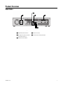
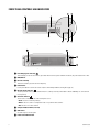
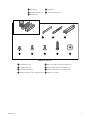
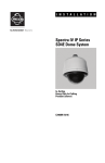
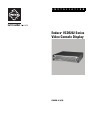
I N S T A L L A T I O N
Endura VCD5202 Series
Video Console Display
®
C3696M-A (6/10)
Contents
Important Notices . . . . . . . . . . . . . . . . . . . . . . . . . . . . . . . . . . . . . . . . . . . . . . . . . . . . . . . . . . . . . . . . . . . . . . . . . . . . . . . . . . . . . . . . . . . . . . . . . . . . . 5
Legal Notice . . . . . . . . . . . . . . . . . . . . . . . . . . . . . . . . . . . . . . . . . . . . . . . . . . . . . . . . . . . . . . . . . . . . . . . . . . . . . . . . . . . . . . . . . . . . . . . . . . . . . 5
Regulatory Notice . . . . . . . . . . . . . . . . . . . . . . . . . . . . . . . . . . . . . . . . . . . . . . . . . . . . . . . . . . . . . . . . . . . . . . . . . . . . . . . . . . . . . . . . . . . . . . . . . 5
Video Quality Caution . . . . . . . . . . . . . . . . . . . . . . . . . . . . . . . . . . . . . . . . . . . . . . . . . . . . . . . . . . . . . . . . . . . . . . . . . . . . . . . . . . . . . . . . . . . . . . 5
Description. . . . . . . . . . . . . . . . . . . . . . . . . . . . . . . . . . . . . . . . . . . . . . . . . . . . . . . . . . . . . . . . . . . . . . . . . . . . . . . . . . . . . . . . . . . . . . . . . . . . . . . . . . . 6
Product Overview. . . . . . . . . . . . . . . . . . . . . . . . . . . . . . . . . . . . . . . . . . . . . . . . . . . . . . . . . . . . . . . . . . . . . . . . . . . . . . . . . . . . . . . . . . . . . . . . . . . . . . 7
Rear Panel. . . . . . . . . . . . . . . . . . . . . . . . . . . . . . . . . . . . . . . . . . . . . . . . . . . . . . . . . . . . . . . . . . . . . . . . . . . . . . . . . . . . . . . . . . . . . . . . . . . . . . . 7
Front Panel Controls and Indicators . . . . . . . . . . . . . . . . . . . . . . . . . . . . . . . . . . . . . . . . . . . . . . . . . . . . . . . . . . . . . . . . . . . . . . . . . . . . . . . . . . . 8
Before You Begin . . . . . . . . . . . . . . . . . . . . . . . . . . . . . . . . . . . . . . . . . . . . . . . . . . . . . . . . . . . . . . . . . . . . . . . . . . . . . . . . . . . . . . . . . . . . . . . . . . . . . . 9
Package Contents . . . . . . . . . . . . . . . . . . . . . . . . . . . . . . . . . . . . . . . . . . . . . . . . . . . . . . . . . . . . . . . . . . . . . . . . . . . . . . . . . . . . . . . . . . . . . . . . 10
Product Serial Number Label Placement . . . . . . . . . . . . . . . . . . . . . . . . . . . . . . . . . . . . . . . . . . . . . . . . . . . . . . . . . . . . . . . . . . . . . . . . . . . . . . 12
Installation . . . . . . . . . . . . . . . . . . . . . . . . . . . . . . . . . . . . . . . . . . . . . . . . . . . . . . . . . . . . . . . . . . . . . . . . . . . . . . . . . . . . . . . . . . . . . . . . . . . . . . . . . . 13
Mounting. . . . . . . . . . . . . . . . . . . . . . . . . . . . . . . . . . . . . . . . . . . . . . . . . . . . . . . . . . . . . . . . . . . . . . . . . . . . . . . . . . . . . . . . . . . . . . . . . . . . . . . 13
Desktop Mounting . . . . . . . . . . . . . . . . . . . . . . . . . . . . . . . . . . . . . . . . . . . . . . . . . . . . . . . . . . . . . . . . . . . . . . . . . . . . . . . . . . . . . . . . . . . 13
Rack Mounting. . . . . . . . . . . . . . . . . . . . . . . . . . . . . . . . . . . . . . . . . . . . . . . . . . . . . . . . . . . . . . . . . . . . . . . . . . . . . . . . . . . . . . . . . . . . . . 13
Hardware Connections . . . . . . . . . . . . . . . . . . . . . . . . . . . . . . . . . . . . . . . . . . . . . . . . . . . . . . . . . . . . . . . . . . . . . . . . . . . . . . . . . . . . . . . . . . . . 17
Unit Startup, Shutdown, and Log Off . . . . . . . . . . . . . . . . . . . . . . . . . . . . . . . . . . . . . . . . . . . . . . . . . . . . . . . . . . . . . . . . . . . . . . . . . . . . . . . . . . . . . 18
Startup . . . . . . . . . . . . . . . . . . . . . . . . . . . . . . . . . . . . . . . . . . . . . . . . . . . . . . . . . . . . . . . . . . . . . . . . . . . . . . . . . . . . . . . . . . . . . . . . . . . . . . . . 18
Shutdown . . . . . . . . . . . . . . . . . . . . . . . . . . . . . . . . . . . . . . . . . . . . . . . . . . . . . . . . . . . . . . . . . . . . . . . . . . . . . . . . . . . . . . . . . . . . . . . . . . . . . . 18
Menu Shutdown . . . . . . . . . . . . . . . . . . . . . . . . . . . . . . . . . . . . . . . . . . . . . . . . . . . . . . . . . . . . . . . . . . . . . . . . . . . . . . . . . . . . . . . . . . . . 18
Orderly Shutdown . . . . . . . . . . . . . . . . . . . . . . . . . . . . . . . . . . . . . . . . . . . . . . . . . . . . . . . . . . . . . . . . . . . . . . . . . . . . . . . . . . . . . . . . . . . 18
Hard Shutdown (not recommended) . . . . . . . . . . . . . . . . . . . . . . . . . . . . . . . . . . . . . . . . . . . . . . . . . . . . . . . . . . . . . . . . . . . . . . . . . . . . . 18
Log Off. . . . . . . . . . . . . . . . . . . . . . . . . . . . . . . . . . . . . . . . . . . . . . . . . . . . . . . . . . . . . . . . . . . . . . . . . . . . . . . . . . . . . . . . . . . . . . . . . . . . . . . . . 18
Troubleshooting . . . . . . . . . . . . . . . . . . . . . . . . . . . . . . . . . . . . . . . . . . . . . . . . . . . . . . . . . . . . . . . . . . . . . . . . . . . . . . . . . . . . . . . . . . . . . . . . . . . . . . 19
Specifications . . . . . . . . . . . . . . . . . . . . . . . . . . . . . . . . . . . . . . . . . . . . . . . . . . . . . . . . . . . . . . . . . . . . . . . . . . . . . . . . . . . . . . . . . . . . . . . . . . . . . . . 20
C3696M-A (6/10)
3
List of Illustrations
1
2
3
4
5
6
7
8
9
10
11
12
13
4
VCD5202 Rear Panel. . . . . . . . . . . . . . . . . . . . . . . . . . . . . . . . . . . . . . . . . . . . . . . . . . . . . . . . . . . . . . . . . . . . . . . . . . . . . . . . . . . . . . . . . . . . . . . 7
VCD5202 Front Panel (Bezel Open). . . . . . . . . . . . . . . . . . . . . . . . . . . . . . . . . . . . . . . . . . . . . . . . . . . . . . . . . . . . . . . . . . . . . . . . . . . . . . . . . . . . 8
VCD5202 Front Panel (Bezel Closed) . . . . . . . . . . . . . . . . . . . . . . . . . . . . . . . . . . . . . . . . . . . . . . . . . . . . . . . . . . . . . . . . . . . . . . . . . . . . . . . . . . 8
Major Package Components. . . . . . . . . . . . . . . . . . . . . . . . . . . . . . . . . . . . . . . . . . . . . . . . . . . . . . . . . . . . . . . . . . . . . . . . . . . . . . . . . . . . . . . . 10
Accessory Pack . . . . . . . . . . . . . . . . . . . . . . . . . . . . . . . . . . . . . . . . . . . . . . . . . . . . . . . . . . . . . . . . . . . . . . . . . . . . . . . . . . . . . . . . . . . . . . . . . . 10
Rack Mount Kit . . . . . . . . . . . . . . . . . . . . . . . . . . . . . . . . . . . . . . . . . . . . . . . . . . . . . . . . . . . . . . . . . . . . . . . . . . . . . . . . . . . . . . . . . . . . . . . . . . 11
Extra Product Serial Number Label. . . . . . . . . . . . . . . . . . . . . . . . . . . . . . . . . . . . . . . . . . . . . . . . . . . . . . . . . . . . . . . . . . . . . . . . . . . . . . . . . . . 12
Chassis Brackets and Rubber Feet . . . . . . . . . . . . . . . . . . . . . . . . . . . . . . . . . . . . . . . . . . . . . . . . . . . . . . . . . . . . . . . . . . . . . . . . . . . . . . . . . . . 13
Assembling a Support Rail . . . . . . . . . . . . . . . . . . . . . . . . . . . . . . . . . . . . . . . . . . . . . . . . . . . . . . . . . . . . . . . . . . . . . . . . . . . . . . . . . . . . . . . . . 14
Inserting the Cage Nuts . . . . . . . . . . . . . . . . . . . . . . . . . . . . . . . . . . . . . . . . . . . . . . . . . . . . . . . . . . . . . . . . . . . . . . . . . . . . . . . . . . . . . . . . . . . 14
Attaching the Support Rails . . . . . . . . . . . . . . . . . . . . . . . . . . . . . . . . . . . . . . . . . . . . . . . . . . . . . . . . . . . . . . . . . . . . . . . . . . . . . . . . . . . . . . . . 15
Mounting the VCD5202 into the Rack . . . . . . . . . . . . . . . . . . . . . . . . . . . . . . . . . . . . . . . . . . . . . . . . . . . . . . . . . . . . . . . . . . . . . . . . . . . . . . . . 16
Tightening the Thumbscrews . . . . . . . . . . . . . . . . . . . . . . . . . . . . . . . . . . . . . . . . . . . . . . . . . . . . . . . . . . . . . . . . . . . . . . . . . . . . . . . . . . . . . . . 16
C3696M-A (6/10)
Important Notices
LEGAL NOTICE
SOME PELCO EQUIPMENT CONTAINS, AND THE SOFTWARE ENABLES, AUDIO/VISUAL AND RECORDING CAPABILITIES, THE IMPROPER USE OF
WHICH MAY SUBJECT YOU TO CIVIL AND CRIMINAL PENALTIES. APPLICABLE LAWS REGARDING THE USE OF SUCH CAPABILITIES VARY
BETWEEN JURISDICTIONS AND MAY REQUIRE, AMONG OTHER THINGS, EXPRESS WRITTEN CONSENT FROM RECORDED SUBJECTS. YOU
ARE SOLELY RESPONSIBLE FOR INSURING STRICT COMPLIANCE WITH SUCH LAWS AND FOR STRICT ADHERENCE TO ANY/ALL RIGHTS OF
PRIVACY AND PERSONALTY. USE OF THIS EQUIPMENT AND/OR SOFTWARE FOR ILLEGAL SURVEILLANCE OR MONITORING SHALL BE DEEMED
UNAUTHORIZED USE IN VIOLATION OF THE END USER SOFTWARE AGREEMENT AND RESULT IN THE IMMEDIATE TERMINATION OF YOUR
LICENSE RIGHTS THEREUNDER.
REGULATORY NOTICE
This device complies with Part 15 of the FCC Rules. Operation is subject to the following two conditions: (1) this device may not cause harmful
interference, and (2) this device must accept any interference received, including interference that may cause undesired operation.
RADIO AND TELEVISION INTERFERENCE
This equipment has been tested and found to comply with the limits of a Class A digital device, pursuant to Part 15 of the FCC rules. These limits
are designed to provide reasonable protection against harmful interference when the equipment is operated in a commercial environment.
This equipment generates, uses, and can radiate radio frequency energy and, if not installed and used in accordance with the instruction manual,
may cause harmful interference to radio communications. Operation of this equipment in a residential area is likely to cause harmful interference
in which case the user will be required to correct the interference at his own expense.
Changes and Modifications not expressly approved by the manufacturer or registrant of this equipment can void your authority to operate this
equipment under Federal Communications Commission’s rules.
This Class A digital apparatus complies with Canadian ICES-003.
Cet appareil numérique de la classe A est conforme à la norme NMB-003 du Canada.
VIDEO QUALITY CAUTION
FRAME RATE NOTICE REGARDING USER-SELECTED OPTIONS
Pelco systems are capable of providing high quality video for both live viewing and playback. However, the systems can be used in lower quality
modes, which can degrade picture quality, to allow for a slower rate of data transfer and to reduce the amount of video data stored. The picture
quality can be degraded by either lowering the resolution, reducing the picture rate, or both. A picture degraded by having a reduced resolution
may result in an image that is less clear or even indiscernible. A picture degraded by reducing the picture rate has fewer frames per second,
which can result in images that appear to jump or move more quickly than normal during playback. Lower frame rates may result in a key event
not being recorded by the system.
Judgment as to the suitability of the products for user’s purposes is solely the user’s responsibility. Users shall determine the suitability of the
products for their own intended application, picture rate and picture quality. In the event user intends to use the video for evidentiary purposes in
a judicial proceeding or otherwise, user should consult with its attorney regarding any particular requirements for such use.
C3696M-A (6/10)
5
Description
The VCD5202 video console display (VCD) delivers virtual matrix functionality for surveillance operators. The VCD5202 uniquely addresses the
requirements of real-time surveillance installations while balancing the complexity introduced by today's IP and megapixel cameras. Each
VCD5202 decodes up to 32 streams, manages elaborate video walls, and provides for CCTV-style keyboard control and management
functionality.
Each VCD5202 is capable of simultaneously decoding sixteen MPEG-4 streams at 4CIF resolution and 30/25 images per second (ips), twelve
H.264 baseline streams at 4CIF resolution and 30/25 ips, or two full 1080p streams in real time. When additional streams are displayed, the
VCD5202 uses the patent-pending EnduraView™ technology to automatically seek out and display a lower resolution, second stream from the
camera. The technology can also reduce the refresh rate to minimize the impact on processing requirements and network overhead. Standard
resolution and megapixel video streams can be displayed in single, 2 x 2, 3 x 3, 4 x 4, 1 + 5, 1 + 12, and 2 + 8 configurations on 4:3 aspect ratio
monitors. For 16:9 aspect ratio monitors, 3 x 2 and 4 x 3 configurations are also available. Any combination of live and playback streams can be
displayed simultaneously, including both live and playback streams from the same camera.
Each VCD5202 drives two high definition monitors (monitor resolutions up to 2560 x 1600) through DVI-I connections. The VCD5202 can also
manage a video wall of monitors attached to network decoders or Microsoft® Windows® workstations, or to a combination of the decoders and
the workstations.
The VCD5202 incorporates a heads-up display designed to provide efficient control while allowing operators to remain focused on the video
being observed. Working in conjunction with the optional KBD5000, the icon-based menu structure is blended across the primary monitor's
display. Shortcut keys on the KBD5000 allow operators to quickly access critical functionality without having to look away from their monitors.
When exporting video, the VCD5202 provides a built-in DVD burner and the option of exporting video on a user-supplied USB memory key. Audio
monitoring is enabled through a built-in speaker in the KBD5000.
6
C3696M-A (6/10)
Product Overview
REAR PANEL
1
2
Figure 1. VCD5202 Rear Panel
C3696M-A (6/10)
ì
Digital Video (DVI) Connectors
ñ
USB 2.0 Ports (6 ea.)
î
Microphone In; Audio Out; Audio In
(reserved for future use)
ó
Power Connector with On/Off Switch
ï
Network Connector (RJ-45)
7
FRONT PANEL CONTROLS AND INDICATORS
03267-39-0020
SN
Figure 2. VCD5202 Front Panel (Bezel Open)
Figure 3. VCD5202 Front Panel (Bezel Closed)
ì
Pelco Badge (power indicator)
The Pelco badge, on the left side of the unit, glows blue when the unit has power. Behind the front bezel, the power indicator LED is white.
î
DVD/CD Drive
ï
Bezel Lock and Key
The bezel lock and key secure the unit from tampering.
ñ
Power Button
Use the power button to turn the unit on and off (refer to Unit Startup, Shutdown, and Log Off on page 18).
ó
Network Activity Indicator
The activity indicator flashes green or red when the unit is sending or receiving network data to indicate 1000 Mbps or a slower network
link, respectively.
r
Unit Status Indicator
The unit status is indicated by one of the following three colors:
• Green: The unit is functioning normally.
• Amber: The unit is either in a configuration mode or in a potential failure condition.
• Red: The unit is in an error condition.
8
s
Configuration/Reset Button (reserved)
t
USB 2.0 Port
One USB 2.0 port on the front panel.
u
Product Serial Number Label
C3696M-A (6/10)
Before You Begin
Endura is a network system that requires a continuous amount of bandwidth to transmit true, live video. Therefore, always include your network
administrator when planning and installing Endura components.
You will also need the following items:
•
Access to an Endura network
–
that is an active, gigabit Ethernet network that supports the full Internet Protocol suite,
–
that is configured with at least one Endura video recorder,
–
that is configured with at least one SM5000 system manager
•
One or more monitors (1280 x 1024 VGA or DVI)
•
Phillips screwdriver (if mounting the unit into a rack)
•
Cat5e (or better) network cable
NOTE: Refer to the software documentation for details on how to configure and operate the system. Do not install other software on this unit as
video performance may suffer.
C3696M-A (6/10)
9
PACKAGE CONTENTS
Figure 4, Figure 5 on page 10, and Figure 6 on page 11 show the contents of the two boxes. When installing the VCD5202, refer to these
diagrams.
Figure 4. Major Package Components
ì
î
ï
VCD5202
Accessory Pack
Important Safety Instructions; Installation manual
Figure 5. Accessory Pack
10
C3696M-A (6/10)
ì
î
ï
Rack Mount Kit
Standard Power Cord (1 ea.)
ñ
ó
Resource Disc
DVI-to-VGA Connector (2 ea.)
Bezel Key (2 ea.)
Figure 6. Rack Mount Kit
ì
î
ï
ñ
C3696M-A (6/10)
Rear Mount Rail (2 ea.)
Front Mount Rail (2 ea.)
Chassis Mounting Brackets
Phillips Pan Head Screw, 10-32 X 0.25-Inch (8 ea.)
ó
r
s
t
Phillips Truss Head Screw, 8-32 X 0.375-Inch (6 ea.)
Phillips Flat Head Screw, 10-32 X 0.5-Inch (4 ea.)
Phillips Pan Head Screw, 10-32 X 0.75-Inch (4 ea.)
Cage Nut, 10-32 (10 ea.)
11
PRODUCT SERIAL NUMBER LABEL PLACEMENT
Product serial number labels help Pelco Product Support identify your system and its factory configuration if your VCD5202 or its components
require service.
Three labels citing your product’s serial number are attached to the VCD5202. One label is attached to the bottom of the VCD5202. A second
label is attached to the front panel of the unit, behind the bezel.
Because rack mounting and other installation options may obscure the factory-applied labels, a third label is provided for you to attach to your
product documentation or another product location that will not be obscured by installation.
To use this label:
1. Locate the small label attached to the outside of the front bezel with a yellow sticker that reads “Extra serial number label: remove prior to
installation.”
2. Remove the yellow sticker.
3. Peel away the backing of the small white label and attach it to this Installation manual, other product documentation, or an unobscured
product location.
03267-39-0020
SN
VCD5200 Series
Figure 7. Extra Product Serial Number Label
12
C3696M-A (6/10)
Installation
MOUNTING
DESKTOP MOUNTING
WARNING: Do not place the VCD5202 on its side; in this position, the unit is likely to fall over and may cause equipment damage or
personal injury.
To mount the VCD5202 on a desktop:
1. Make sure the rubber feet are installed to prevent surface damage. If not, secure each rubber foot to the bottom panel of the unit (refer to
Figure 8). Use the four 8-32 x 0.375-inch Phillips pan head screws (supplied).
2. Optional: Remove the two chassis brackets (if attached) from the sides of the unit. Use a Phillips screwdriver to remove the eight
10-32 x 0.25-inch Phillips pan head screws (supplied, four per bracket). Save the brackets and screws for possible future use.
3. Position the unit to allow for cable and power cord clearance at the rear of the unit. Make sure that the air flow around the unit is not
obstructed.
(4) SCREWS
PER BRACKET,
10.32 X 0.25-INCH
PHILLIPS PAN HEAD
CHASSIS
BRACKET
VCD52
00 Series
RUBBER FEET
(4) SCREWS,
8-32 X 0.25-INCH
PHILLIPS PAN HEAD
Figure 8. Chassis Brackets and Rubber Feet
RACK MOUNTING
The VCD5202 mounts into an industry-standard 19-inch (48 cm) equipment rack. The VCD5202 occupies two rack units (3.5 inches or 8.9 cm) of
vertical rack space. The hardware necessary to mount the VCD5202 into a rack is supplied with the unit.
The rack must meet the following requirements:
•
Rack standard: 19-inch EIA-310-D compliant (rear column required).
•
Rack column depth: 20 to 30 inches (50.8 to 76.2 cm).
•
Column mounting hole provisions: 10-32 UNF-2B threaded holes or square window holes on front and rear columns.
•
Door systems (optional): Front doors must have at least 2 inches (5.1 cm) between the VCD5202 bezel and the inside of the door.
Rear doors may be used only on rack columns that are more than 26 inches (66.0 cm) deep.
WARNING: Slots and openings in the cabinet provide ventilation to prevent the unit from overheating. Do not block these openings.
Never place the unit near or over a radiator or heat register. When placing the unit in a built-in installation, such as a rack, be sure to
provide proper ventilation.
NOTE: Figure 6 on page 11 identifies each piece of hardware for this procedure.
C3696M-A (6/10)
13
To install the VCD5202 in a rack:
1. If chassis mounting brackets are not attached: Attach one mounting bracket (supplied) to each side of the VCD5202. Use four
10-32 x 0.25-inch Phillips pan head screws (supplied) for each bracket. Attach the brackets so that the tapered ends are positioned toward
the rear of the VCD5202 (refer to Figure 8 on page 13).
2. Remove the four rubber feet from the underside of the unit if they are attached. Save the rubber feet and screws for possible future use.
3. Attach one front-mount rail (supplied) to one rear-mount rail (supplied). Make sure the rails are mounted back to back, as shown in Figure 9.
Use three 8-32 x 0.375-inch Phillips truss head screws (supplied) in any of the available holes. Leave the screws loose until step 8.
(3) SCREWS, 8-32 X 0.375
PHILLIPS TRUSS HEAD
Figure 9. Assembling a Support Rail
4. Repeat step 3 for the other rail set.
5. If installing the unit into a square-hole rack: Insert 10 cage nuts (supplied) into the square-hole rack as shown in Figure 10.
CAGE NUT
Figure 10. Inserting the Cage Nuts
14
C3696M-A (6/10)
6. Attach one support rail assembly (supplied) to the equipment rack in the desired location (refer to Figure 11).
NOTE: The support rail assemblies are identical and may be used on either the right or left side of the rack.
a.
Position the ear of the front-mount rail against the front of the equipment rack. Align the top and bottom holes in the ear of the rail
with the threaded holes (or cage nuts) in the rack.
b.
Using two 10-32 x 0.5-inch Phillips flat head screws (supplied), attach the ear of the rail to the front of the rack. Insert the screws from
the outside of the rack, pointing rearward.
c.
Adjust the rails to the correct depth of the equipment rack by sliding the rear-mount rail to the back of the equipment rack.
d.
Position the ear of the rear-mount rail against the rear exterior of the equipment rack. Align the top and bottom holes in the ear of the
rail section with the threaded holes (or cage nuts) in the equipment rack.
e.
Using two 10-32 x 0.75-inch Phillips pan head screws (supplied), attach the ear of the rail to the rear of the rack. Insert the screws
from the outside of the rack, pointing forward.
RACK FRONT
RACK REAR
(4) SCREWS,
10-32 X 0.5-INCH
PHILLIPS FLAT HEAD
(4) SCREWS,
10-32 X 0.75-INCH
PHILLIPS PAN HEAD
FRONT- MOUNT RAIL
REAR-MOUNT RAIL
Figure 11. Attaching the Support Rails
7. Repeat step 6 for the second support rail assembly.
8. Tighten the 8-32 x 0.375-inch Phillips truss head screws that were attached to the front- and rear-mount rails in step 3.
C3696M-A (6/10)
15
9. Place the unit onto the mount rails by sliding the chassis brackets onto the rails (refer to Figure 12). This step may require two people to lift
and slide the unit into place. The unit should slide in and out of the rack easily.
WARNING: When sliding out the VCD5202, be careful not to let the unit fall out of the rack.
1
2
Figure 12. Mounting the VCD5202 into the Rack
10. After the unit is in place, tighten the two thumbscrews to secure the unit to the rack.
THUMBSCREW
THUMBSCREW
Figure 13. Tightening the Thumbscrews
16
C3696M-A (6/10)
HARDWARE CONNECTIONS
1. Connect video output.
The VCD5202 can support two video outputs to a digital video interface (DVI) output. Connect a DVI cable from the DVI output to the digital
monitor’s input connector. To connect a VGA monitor to this output, use a DVI-to-VGA adapter plug (supplied).
2. Connect a 1000Base-T Cat5e (or better) cable to the network connector on the rear panel and to the network switch.
3. Use the USB 2.0 ports (front or rear of the unit) to connect a KBD5000 keyboard (sold separately). USB cables connecting the KBD5000 to
the VCD5202 may be no more than16.4 ft (5 m) long. Use USB 2.0-compatible extenders for longer distances. All audio in and out are
connected to the KBD5000.
4. Connect one end of the power cord (supplied) to the rear of the unit, connect the other end to a power source, and then turn on the power
switch. The VCD5202 uses a 100 to 240 VAC power supply.
WARNING: Turning off the power switch shuts down the unit. Do not turn off the power in this manner unless the unit does not shut down
properly through the Linux® operating system. Turning off the unit in this manner can result in unexpected data loss in the software.
5. Turn on the unit (refer to Startup on page 18).
6. Close and lock the bezel.
C3696M-A (6/10)
17
Unit Startup, Shutdown, and Log Off
STARTUP
1. Unlock and open the bezel.
2. Quickly press and release the power button. The power indicator glows white.
3. Close and lock the bezel. The Pelco badge glows blue and the login screen appears; the unit status indicator glows solid green after the unit
starts; and the network status indicator flashes green or red to show network activity. Refer to Front Panel Controls and Indicators on
page 8.
4. Enter a user ID and password using the KBD5000 keypad to log into the system (refer to the VCD5202 Operation manual).
SHUTDOWN
The following three options can be used to shut down the VCD5202. For security purposes, only a user with administrative-level permissions can
shut down the unit.
WARNING: Do not shut down the VCD5202 by performing a hard shutdown, unless necessary. Doing so can cause data loss or may
corrupt the database.
MENU SHUTDOWN
1. From the Login screen, select a user ID with administrative-level permissions, and then enter the appropriate password.
NOTE: If you are already logged on, use the on-screen menus to log off, and then follow the steps below.
2. Select Shut Down, or move the joystick until Shut Down is selected, and then press the joystick trigger. The VCD5202 saves all
configuration information and shuts down.
ORDERLY SHUTDOWN
1. Unlock and open the bezel.
2. Quickly press and release the power button. The system safely closes all running processes, and then the unit shuts down.
3. Close and lock the bezel.
HARD SHUTDOWN (NOT RECOMMENDED)
1. Unlock and open the bezel.
2. Press and hold the power button until the unit shuts down.
3. Close and lock the bezel.
LOG OFF
You can log off from the system without shutting down the unit.
NOTE: With automatic login disabled, the Login dialog box remains on the screen. You or another operator can log back on to the system.
From the Main menu, select Logout. The system closes your work session and the Login dialog box appears.
18
C3696M-A (6/10)
Troubleshooting
Consult the software configuration manual for detailed information on setting up devices that are attached to the Endura system. The following
table provides suggestions to common issues related to the VCD5202. If these instructions fail to solve your problem, contact Pelco Product
Support at 1-800-289-9100 (USA and Canada) or +1-559-292-1981 (international) for assistance.
Note the following information before calling Pelco:
•
Unit serial number: Located on the product label on the front panel of the unit.
•
Unit software version: Located in the Advanced Properties in the unit’s system configuration software.
NOTE: Do not try to repair the unit yourself. Opening the unit immediately voids any warranty. Leave maintenance and repairs to qualified
technical personnel. Exchange the defective unit and return it for repair.
Table A. Troubleshooting the VCD5202
Problem
Possible Causes
Suggested Solution
Front panel indicators not lit.
Power turned off.
Check the power supply.
Turn on the power switch.
Network connection problem.
Faulty network connections.
Visually inspect all network cables and connectors at the unit and
the network switch.
Check the indicators on the network switch.
Other network connectivity issues.
Contact your network administrator or Endura-certified technician.
C3696M-A (6/10)
19
Specifications
SYSTEM
Processor
Intel® Core™2 Quad Q9400
Internal Memory
4 GB RAM
Operating System
Linux
User Interface
Icon-based, heads-up display
Video System
2, DVI-I video outputs
VIDEO
Video Standards
XVGA (2560 X 1600)
60 Hz capability for NTSC
75 Hz capability for PAL
Video Coding
MPEG-4, H.264 baseline, main, and high profile
Video Outputs
2 DVI or VGA outputs (2 DVI-to-VGA adapters supplied)
AUDIO
Audio Decoding
G.711 speech codec
Audio Bit Rate
64 kbps
Audio Inputs
Microphone and line in through KBD5000
Audio Outputs
Speaker or line out through KBD5000
PTZ CONTROL
PTZ Interface
Through KBD5000
NETWORK
Interface
Gigabit Ethernet RJ-45 port (1000Base-T)
AUXILIARY INTERFACES
USB Ports
7 USB 2.0 ports (1 front, 6 rear)
FRONT PANEL FUNCTIONS/INDICATORS
20
DVD±RW/CD-RW Drive
CD Read/Write Speed
CD Rewrite Speed
DVD Read/Write Speed
DVD Dual Layer Read/Write Speed
24X
24X
8X
8X/6X
Buttons
Power, configuration/reset
Indicators
Power
Network Activity
Unit Status
Blue for power
Green or red for activity
Green, yellow, red
C3696M-A (6/10)
POWER
Power Input
100 to 240 VAC, 50/60 Hz, autoranging
Power Supply
Internal
Power Consumption
100 VAC
115 VAC
220 VAC
Operating Maximum
160 W, 1.60 A, 547 BTU/H
160 W, 1.39 A, 547 BTU/H
160 W, 0.72 A, 547 BTU/H
Power Cord
1, USA standard (117 VAC, 3 prongs, molded connector, 6 ft or 1.8 m);
1, European standard (220 VAC, 3 prongs, molded connector, 6 ft or 1.8 m);
1, United Kingdom standard (250 VAC, 3 prongs, molded connector, 6 ft or 1.8 m);
1, Australian standard (250 VAC, 3 prongs, molded connector, 6 ft or 1.8 m); or
1, Argentinian standard (250 VAC, 3 prongs, molded connector, 6 ft or 1.8 m)
NOTE: Units shipped to China do not include a power cord.
ENVIRONMENTAL
Operating Temperature
50° to 95°F (10° to 35°C) at unit air intake (front of unit)
Storage Temperature
-40° to 149°F (-40° to 65°C)
Operating Humidity
20% to 80%, noncondensing
Maximum Humidity Gradient
10% per hour
Operating Altitude
-50 to 10,000 ft (-15 to 3,048 m)
Operating Vibration
0.25 G at 3 Hz to 200 HZ at a sweep rate of 0.5 octave/min.
PHYSICAL
Construction
Steel cabinet
Finish
Front panel
Chassis
Gray metallic with black end caps
Black matte finish
Dimensions
17.0" D x 17.1" W x 3.5" H
(43.2 x 43.4 x 8.9 cm)
Mounting
Desktop (feet) or rack (2 RU per unit)
Unit Weight
28.8 lb (13.06 kg)
STANDARDS/ORGANIZATIONS
•
Pelco is a member of the MPEG-4 Industry Forum
•
Pelco is a member of the Universal Plug and Play (UPnP) Forum, Steering Committee
•
Pelco is a member of the Universal Serial Bus (USB) Implementers Forum
•
Pelco is a contributor to the International Standards for Organization / Electrotechnical Commission (ISO/IEC) Joint Technical Committee 1
(JTC1), “Information Technology,” Subcommittee 29, Working Group 11
•
Compliance, ISO/IEC 14496 standard (also known as MPEG-4)
•
Compliance, International Telecommunication Union (ITU) Recommendation G.711, “Pulse Code Modulation (PCM) of Voice Frequencies”
C3696M-A (6/10)
21
PRODUCT WARRANTY AND RETURN INFORMATION
WARRANTY
Pelco will repair or replace, without charge, any merchandise proved defective in
material or workmanship for a period of one year after the date of shipment.
Exceptions to this warranty are as noted below:
• Five years:
– Fiber optic products
– Unshielded Twisted Pair (UTP) transmission products
– CC3701H-2, CC3701H-2X, CC3751H-2, CC3651H-2X, MC3651H-2, and
MC3651H-2X camera models
• Three years:
– Pelco-designed fixed network cameras and network dome cameras with
Sarix™ technology.
– Pelco-branded fixed camera models (CCC1390H Series, C10DN Series,
C10CH Series, and IP3701H Series)
– EH1500 Series enclosures
– Spectra® IV products (including Spectra IV IP)
– Camclosure® Series (IS, ICS, IP) integrated camera systems
– DX Series digital video recorders (except DX9000 Series which is covered
for a period of one year), DVR5100 Series digital video recorders, Digital
Sentry® Series hardware products, DVX Series digital video recorders, and
NVR300 Series network video recorders
– Endura® Series distributed network-based video products
– Genex® Series products (multiplexers, server, and keyboard)
– PMCL200/300/400 Series LCD monitors
– PMCL5xx Series FHD monitors
• Two years:
– Standard varifocal, fixed focal, and motorized zoom lenses
– DF5/DF8 Series fixed dome products
– Legacy® Series integrated positioning systems
– Spectra III™, Spectra Mini, Spectra Mini IP, Esprit®, ExSite®, and PS20
scanners, including when used in continuous motion applications.
– Esprit Ti and TI2500 Series thermal imaging products
– Esprit and WW5700 Series window wiper (excluding wiper blades).
– CM6700/CM6800/CM9700 Series matrix
– Digital Light Processing (DLP®) displays (except lamp and color wheel). The
lamp and color wheel will be covered for a period of 90 days. The air filter is
not covered under warranty.
– Intelli-M® eIDC controllers
• One year:
– Video cassette recorders (VCRs), except video heads. Video heads will be
covered for a period of six months.
• Six months:
– All pan and tilts, scanners, or preset lenses used in continuous motion
applications (preset scan, tour, and auto scan modes).
Pelco will warrant all replacement parts and repairs for 90 days from the date of
Pelco shipment. All goods requiring warranty repair shall be sent freight prepaid
to a Pelco designated location. Repairs made necessary by reason of misuse,
alteration, normal wear, or accident are not covered under this warranty.
Pelco assumes no risk and shall be subject to no liability for damages or loss
resulting from the specific use or application made of the Products. Pelco’s liability
for any claim, whether based on breach of contract, negligence, infringement of
any rights of any party or product liability, relating to the Products shall not exceed
the price paid by the Dealer to Pelco for such Products. In no event will Pelco be
liable for any special, incidental, or consequential damages (including loss of use,
loss of profit, and claims of third parties) however caused, whether by the
negligence of Pelco or otherwise.
The above warranty provides the Dealer with specific legal rights. The Dealer may
also have additional rights, which are subject to variation from state to state.
If a warranty repair is required, the Dealer must contact Pelco at (800) 289-9100 or
(559) 292-1981 to obtain a Repair Authorization number (RA), and provide the
following information:
1. Model and serial number
2. Date of shipment, P.O. number, sales order number, or Pelco invoice number
3. Details of the defect or problem
If there is a dispute regarding the warranty of a product that does not fall under
the warranty conditions stated above, please include a written explanation with
the product when returned.
Method of return shipment shall be the same or equal to the method by which the
item was received by Pelco.
RETURNS
To expedite parts returned for repair or credit, please call Pelco at (800) 289-9100
or (559) 292-1981 to obtain an authorization number (CA number if returned for
credit, and RA number if returned for repair) and designated return location.
All merchandise returned for credit may be subject to a 20 percent restocking and
refurbishing charge.
Goods returned for repair or credit should be clearly identified with the assigned
CA or RA number and freight should be prepaid.
2-10-10
The materials used in the manufacture of this document and its components are compliant to the requirements of Directive 2002/95/EC.
This equipment contains electrical or electronic components that must be recycled properly to comply with Directive 2002/96/EC of the European Union
regarding the disposal of waste electrical and electronic equipment (WEEE). Contact your local dealer for procedures for recycling this equipment.
REVISION HISTORY
Manual #
C3696M
C3696M-A
Date
8/09
6/10
Comments
Original version.
Modified power consumption values in the specifications section.
Pelco, the Pelco logo, and other trademarks associated with Pelco products referred to in this publication are trademarks of Pelco, Inc. or its affiliates.
All other product names and services are the property of their respective companies.
Product specifications and availability are subject to change without notice.
© Copyright 2010, Pelco, Inc.
All rights reserved.
www.pelco.com
Pelco, Inc. Worldwide Headquarters 3500 Pelco Way Clovis, California 93612 USA
USA & Canada Tel (800) 289-9100 Fax (800) 289-9150
International Tel +1 (559) 292-1981 Fax +1 (559) 348-1120