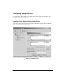
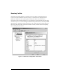
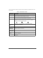
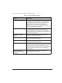
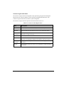
1
Endurance FTvirtual Server Administrator’s Guide Marathon Technologies Corporation Fault and Disaster Tolerant™ Solutions for Windows Environments Release 6.1.1 June 2005 NOTICE Marathon Technologies Corporation reserves the right to make improvements to this guide and the product it describes at any time and without further notice. COPYRIGHT Marathon Technologies Corporation. 1996-2005. All rights reserved. This guide is copyrighted, and all rights are reserved. No part of this guide or the products it describes may be reproduced by any means or in any form, without prior consent in writing from Marathon Technologies Corporation. Printed in the U.S.A. U.S. Patent Numbers: 5,600,784; 5,615,403; 5,787,485; 5,790,397; 5,896,523; 5,956,474; 5,983,371; 6,038,685; 6,205,565; and 6,728,898. European Patent Numbers: EP0974912; EP0731945; EP0993633; EP0986784, and EP1000397. Other patents pending. SOFTWARE COPYRIGHT NOTICE The software described in this document is covered by the following copyright: Marathon Technologies Corporation. 1996-2005. TRADEMARK NOTICE Endurance, Marathon Assured Availability, SplitSite, Marathon FTvirtual Server, and the Marathon logo are either registered trademarks or trademarks of Marathon Technologies Corporation in the United States and/or other countries. Microsoft, MS-DOS, and Windows are registered trademarks of Microsoft Corporation in the United States and/or other countries. All other brands and product names are trademarks of their respective companies or organizations. SOFTWARE REVISION The revision of the software that this document supports is Revision 6.1.1. Marathon Technologies Corporation, Inc. 295 Foster Street, Littleton, MA 01460 (978) 489.1100 or (888) 682.1142 www.marathontechnologies.com ii Contents Preface Chapter 1 — Starting, Shutting Down, and Restarting Endurance FTvirtual Server Methods for Performing Management Tasks . . . . . . . . . . . . . . . . . . . . . . 1-2 Starting A Endurance Configuration . . . . . . . . . . . . . . . . . . . . . . . . . . 1-3 Shutting Down the Endurance Configuration. . . . . . . . . . . . . . . . . . . . . . 1-4 Starting the FTvirtual Server . . . . . . . . . . . . . . . . . . . . . . . . . . . . . . 1-7 Shutting Down the Endurance FTvirtual Server . . . . . . . . . . . . . . . . . . . . 1-9 Chapter 2 — FTvirtual Server Desktop FTvirtual Server Desktop . . . . . . . . . . . . . . . . . . . . . . . . . . . . . . . . 2-2 FTvirtual Server Desktop Display During Boot . . . . . . . . . . . . . . . . . . 2-2 Video Considerations . . . . . . . . . . . . . . . . . . . . . . . . . . . . . . . . . . 2-3 Using the FTvirtual Server Desktop . . . . . . . . . . . . . . . . . . . . . . . . . . 2-5 FTvirtual Server Desktop Modes . . . . . . . . . . . . . . . . . . . . . . . . . 2-5 FTvirtual Server and CoServer Display Settings . . . . . . . . . . . . . . . . . . . . 2-8 Wallpaper Considerations . . . . . . . . . . . . . . . . . . . . . . . . . . . . . 2-8 Setting Video Resolution and Refresh Frequency . . . . . . . . . . . . . . . . . 2-9 Chapter 3 — Endurance Device Redirector Introduction . . . . . . . . . . . . . . . . . . . . . . . . . . . . . . . . . . . . . . . 3-2 Starting the Endurance Device Redirector . . . . . . . . . . . . . . . . . . . . . . . 3-3 Icons, Menus, and Buttons . . . . . . . . . . . . . . . . . . . . . . . . . . . . . 3-5 Contents iii Configuring Storage Devices . . . . . . . . . . . . . . . . . . . . . . . . . . . . . 3-11 Updating Device Settings When Adding Disks. . . . . . . . . . . . . . . . . . 3-11 Updating Device Settings When Removing Disks . . . . . . . . . . . . . . . . 3-13 Updating Device Settings When Replacing Devices . . . . . . . . . . . . . . . 3-14 Updating Device Settings When Adding CD-ROMs, Medium Changers, and Tape Drives . . . . . . . . . . . . . . . . . . . . . . . . . . . . . . . . . . . . . . . 3-16 Updating Device Settings When Removing CD-ROMs, Medium Changers, and Tape Drives . . . . . . . . . . . . . . . . . . . . . . . . . . . . . . . . . . . . . . . 3-17 Managing Virtual Disks . . . . . . . . . . . . . . . . . . . . . . . . . . . . . . . . 3-18 Creating a Virtual Disk . . . . . . . . . . . . . . . . . . . . . . . . . . . . . . 3-19 Mounting a Virtual Disk . . . . . . . . . . . . . . . . . . . . . . . . . . . . . 3-20 Redirecting a Virtual Disk . . . . . . . . . . . . . . . . . . . . . . . . . . . . 3-21 Dismounting a Virtual Disk . . . . . . . . . . . . . . . . . . . . . . . . . . . . 3-23 Deleting a Virtual Disk . . . . . . . . . . . . . . . . . . . . . . . . . . . . . . 3-24 Replacing a Virtual Disk . . . . . . . . . . . . . . . . . . . . . . . . . . . . . 3-25 Moving a Virtual Disk . . . . . . . . . . . . . . . . . . . . . . . . . . . . . . 3-27 Copying a Virtual Disk . . . . . . . . . . . . . . . . . . . . . . . . . . . . . . 3-28 Configuring Ethernet Adapters . . . . . . . . . . . . . . . . . . . . . . . . . . . . 3-29 Updating Device Settings When Adding Ethernet Adapters . . . . . . . . . . . 3-29 Updating Device Settings When Removing Ethernet Adapters . . . . . . . . . 3-33 Displaying and Editing Device Properties . . . . . . . . . . . . . . . . . . . . . . . 3-38 Resolving Conflicts . . . . . . . . . . . . . . . . . . . . . . . . . . . . . . . . 3-40 Removed Devices . . . . . . . . . . . . . . . . . . . . . . . . . . . . . . . . . 3-41 Chapter 4 — Endurance Manager Overview . . . . . . . . . . . . . . . . . . . . . . . . . . . . . . . . . . . . . . . . . 4-2 Starting the Endurance Manager . . . . . . . . . . . . . . . . . . . . . . . . . . . . . 4-3 Connecting to the Host . . . . . . . . . . . . . . . . . . . . . . . . . . . . . . . 4-3 Main Window . . . . . . . . . . . . . . . . . . . . . . . . . . . . . . . . . . . 4-5 Using the Endurance Manager . . . . . . . . . . . . . . . . . . . . . . . . . . . . . . 4-8 Setting Defaults for the Endurance Manager . . . . . . . . . . . . . . . . . . . 4-10 Monitoring the Endurance Configuration . . . . . . . . . . . . . . . . . . . . . . . 4-12 Viewing Status . . . . . . . . . . . . . . . . . . . . . . . . . . . . . . . . . . 4-12 Component Status Window . . . . . . . . . . . . . . . . . . . . . . . . . . . . 4-13 iv Endurance FTvirtual Server Administrator’s Guide Endurance Component States . . . . . . . . . . . . . . . . . . . . . . . . . . . 4-14 Mirror Copy Status Window . . . . . . . . . . . . . . . . . . . . . . . . . . 4-31 Component Properties Window . . . . . . . . . . . . . . . . . . . . . . . . . 4-32 Managing CoServer Link Communications . . . . . . . . . . . . . . . . . . . . . 4-33 Optimizing CoServer Link Communications . . . . . . . . . . . . . . . . . . . 4-33 Examining CoServer Link Properties and Status . . . . . . . . . . . . . . . . . 4-35 Managing SplitSite Operations . . . . . . . . . . . . . . . . . . . . . . . . . . . . 4-36 Enabling SplitSite Operations . . . . . . . . . . . . . . . . . . . . . . . . . . . 4-36 Identifying The Preferred CoServer For Surviving Failures . . . . . . . . . . . . 4-37 Configuring Quorum Services . . . . . . . . . . . . . . . . . . . . . . . . . . . 4-38 Managing the Components . . . . . . . . . . . . . . . . . . . . . . . . . . . . . . 4-43 Endurance Configuration Options . . . . . . . . . . . . . . . . . . . . . . . . . 4-43 FTvirtual Server Options . . . . . . . . . . . . . . . . . . . . . . . . . . . . . 4-44 CoServer1 and CoServer2 Options. . . . . . . . . . . . . . . . . . . . . . . . 4-45 CoServer Link Options. . . . . . . . . . . . . . . . . . . . . . . . . . . . . . . 4-46 Disk Options . . . . . . . . . . . . . . . . . . . . . . . . . . . . . . . . . . . 4-47 Networks Options . . . . . . . . . . . . . . . . . . . . . . . . . . . . . . . . . 4-48 Input Devices Options . . . . . . . . . . . . . . . . . . . . . . . . . . . . . . 4-49 Menus . . . . . . . . . . . . . . . . . . . . . . . . . . . . . . . . . . . . . . . . . 4-50 File Menu. . . . . . . . . . . . . . . . . . . . . . . . . . . . . . . . . . . . . . 4-50 View Menu . . . . . . . . . . . . . . . . . . . . . . . . . . . . . . . . . . . . 4-50 Manage Menu . . . . . . . . . . . . . . . . . . . . . . . . . . . . . . . . . . 4-51 Help Menu . . . . . . . . . . . . . . . . . . . . . . . . . . . . . . . . . . . . 4-51 Using the Endurance Manager on a Remote Workstation . . . . . . . . . . . . . . 4-53 Installing and Uninstalling the Remote Endurance Manager . . . . . . . . . . . 4-54 Security Features for Remote Use of Endurance Manager . . . . . . . . . . . . 4-54 Chapter 5 — Troubleshooting Monitoring and Managing Faults . . . . . . . . . . . . . . . . . . . . . . . . . . . . 5-2 Setting Up Management Agents . . . . . . . . . . . . . . . . . . . . . . . . . . 5-2 Reconfiguring Port Numbers. . . . . . . . . . . . . . . . . . . . . . . . . . . . 5-2 Configuring System Event Notification . . . . . . . . . . . . . . . . . . . . . . 5-3 Viewing System Events . . . . . . . . . . . . . . . . . . . . . . . . . . . . . . 5-3 Contents v Diagnosing Faults . . . . . . . . . . . . . . . . . . . . . . . . . . . . . . . . . . . . 5-4 Isolating Faults . . . . . . . . . . . . . . . . . . . . . . . . . . . . . . . . . . . . . 5-5 Correcting Faults . . . . . . . . . . . . . . . . . . . . . . . . . . . . . . . . . . . . 5-6 Chapter 6 — Endurance Tools MTCCONS . . . . . . . . . . . . . . . . . . . . . . . . . . . . . . . . . . . . . . . 6-2 Installation Verification Procedure (IVP) . . . . . . . . . . . . . . . . . . . . . . . . 6-4 MTCEINFO Utility . . . . . . . . . . . . . . . . . . . . . . . . . . . . . . . . . . . 6-5 Running MTCEINFO . . . . . . . . . . . . . . . . . . . . . . . . . . . . . . . . 6-5 Appendix A — Endurance VFT MIB and SNMP Implementation Overview of the Endurance VFT SNMP MIB and Extension Agent . . . . . . . . . A-2 The Endurance VFT SNMP MIB . . . . . . . . . . . . . . . . . . . . . . . . . .A-2 The Endurance FTvirtual Server SNMP Extension Agent . . . . . . . . . . . . .A-2 MIB Naming Tree . . . . . . . . . . . . . . . . . . . . . . . . . . . . . . . . . . . A-4 Endurance Sub-tree of the MIB . . . . . . . . . . . . . . . . . . . . . . . . . . .A-4 Endurance VFT MIB Sub-tree . . . . . . . . . . . . . . . . . . . . . . . . . . .A-6 Manageable Objects. . . . . . . . . . . . . . . . . . . . . . . . . . . . . . . . .A-7 SNMP Traps . . . . . . . . . . . . . . . . . . . . . . . . . . . . . . . . . . . . . . A-9 Configuring SNMP to Send Traps to Remote Management Systems . . . . . . . . . A-23 Glossary vi Endurance FTvirtual Server Administrator’s Guide Tables 2-1 2-2 3-1 3-2 3-3 3-4 4-1 4-2 4-3 4-4 4-5 4-6 4-7 4-8 4-9 4-10 4-11 4-12 4-13 4-14 4-15 4-16 4-17 4-18 4-19 4-20 4-21 4-22 4-23 5-1 6-1 FTvirtual Server Video Recommendations . . . . . . Video Mode Options . . . . . . . . . . . . . . . . . . Endurance Device Redirector Icons . . . . . . . . . . Endurance Device Redirector Toolbar Icons . . . . . Endurance Device Redirector Menus . . . . . . . . . Endurance Device Redirector Button Information. . . Connect to Host Settings Descriptions . . . . . . . . Main Window Contents . . . . . . . . . . . . . . . . Options Window Settings . . . . . . . . . . . . . . . Component Status Window . . . . . . . . . . . . . . State Icon and Color Descriptions . . . . . . . . . . . Endurance Configuration States . . . . . . . . . . . . FTvirtual Server States. . . . . . . . . . . . . . . . . Virtual Server States . . . . . . . . . . . . . . . . . . CoServer States . . . . . . . . . . . . . . . . . . . . CoServer Link Adapter States . . . . . . . . . . . . . CoServer Link Adapter States . . . . . . . . . . . . . Disk States . . . . . . . . . . . . . . . . . . . . . . . Ethernet Adapter States . . . . . . . . . . . . . . . . Input Devices States . . . . . . . . . . . . . . . . . . CD-ROM, Medium Changers, and Tape Drive States. Endurance Configuration Options . . . . . . . . . . . FTvirtual Server Options. . . . . . . . . . . . . . . . CoServer Options . . . . . . . . . . . . . . . . . . . CoServer Link Options. . . . . . . . . . . . . . . . . Disk Options . . . . . . . . . . . . . . . . . . . . . . Network Options . . . . . . . . . . . . . . . . . . . . Input Device Options . . . . . . . . . . . . . . . . . Help Menu Options . . . . . . . . . . . . . . . . . . Diagnosing Faults . . . . . . . . . . . . . . . . . . . MTCCONS Parameters . . . . . . . . . . . . . . . . . . . . . . . . . . . . . . . . . . . . . . . . . . . . . . . . . . . . . . . . . . . . . . . . . . . . . . . . . . . . . . . . . . . . . . . . . . . . . . . . . . . . . . . . . . . . . . . . . . . . . . . . . . . . . . . . . . . . . . . . . . . . . . . . . . . . . . . . . . . . . . . . . . . . . . . . . . . . . . . . . . . . . . . . . . . . . . . . . . . . . . . . . . . . . . . . . . . . . . . . . . . . . . . . . . . . . . . . . . . . . . . . . . . . . . . . . . . . . . . . . . . . . . . . . . . . . . . . . . . . . . . . . . . . . . . . . . . . . . . . . . . . . . . . . . . . . . . . . . . . . . . . . . . . . . . . . . . . . . . . . . . . . . . . . . . . . . . . . . . . . . . . . . . . . . . . . . . . . . . . . . . . . . . . . . . . . . . . . . . . . . . . . . . . . . . . . . . . . . . . . . . . . . . . . . . . . . . . . . . . . . . . . . . . . . . . . . . . . . . 2-3 2-5 3-5 3-6 3-8 3-12 . 4-4 . 4-7 4-11 4-14 4-15 4-17 4-18 4-19 4-20 4-22 4-23 4-24 4-27 4-29 4-30 4-43 4-44 4-45 4-46 4-47 4-48 4-49 4-52 . 5-4 . 6-2 vii A-1 A-2 A-3 A-4 A-5 A-6 A-7 A-8 viii Endurance VFT MIB and Extension Agent Files. . . . . . . Subtree Nodes within the Endurance MIB . . . . . . . . . . Endurance Vft MIBv1 Sub-tree Nodes . . . . . . . . . . . Trap Name Severity Levels Indicating State Information . . System Information Variables At the Beginning of All Traps System Information Variables At the End of All Traps . . . Device Trap Names and Child Numbers . . . . . . . . . . . Optional Device Specific Variables . . . . . . . . . . . . . . . . . . . . . . . . . . . . . . . . . . . . . . . . . . . . . . . . . . . . . . . . . . . . . . . . . . . . . . . . . . . . . . . . . . . . . . . . . . . . . . . . . . . . . A-3 A-5 A-7 A-9 A-10 A-10 A-11 A-18 Endurance FTvirtual Server Administrator’s Guide Figures 3-1 3-2 3-3 3-4 3-5 3-6 3-7 3-8 3-9 3-10 3-11 3-12 4-1 4-2 4-3 4-4 4-5 4-6 4-7 4-8 4-9 4-10 4-11 4-12 4-13 4-14 4-15 A-1 A-2 A-3 A-4 Endurance Device Redirector Main Window . . . . . . . Device Redirector Connections Dialog Box . . . . . . . Add Disks Screen . . . . . . . . . . . . . . . . . . . . . Replace Disks Screen . . . . . . . . . . . . . . . . . . . Virtual Disks in the Device Redirector . . . . . . . . . . Redirect Virtual Disks Screen . . . . . . . . . . . . . . . Replace Virtual Disks Screen . . . . . . . . . . . . . . . Adding Redirected Adapter Screen . . . . . . . . . . . . Removing a Redirected Adapter Screen . . . . . . . . . Network Adapters Uninstall Screen . . . . . . . . . . . . Sample Device Properties Screen . . . . . . . . . . . . . Endurance Configuration with Conflicts . . . . . . . . . Connect to Host Dialog Box . . . . . . . . . . . . . . . Main Window FTvirtual Server View . . . . . . . . . . Main Window CoServer View . . . . . . . . . . . . . . Menu Bar . . . . . . . . . . . . . . . . . . . . . . . . . Pop-up Menu . . . . . . . . . . . . . . . . . . . . . . . Pop-up Menus on the Component Status Window . . . . Tool-tip Text Example . . . . . . . . . . . . . . . . . . Options Window . . . . . . . . . . . . . . . . . . . . . Component Status Window . . . . . . . . . . . . . . . . CoServer View Showing Status Icons . . . . . . . . . . Mirror Copy Status Window . . . . . . . . . . . . . . . File Menu . . . . . . . . . . . . . . . . . . . . . . . . . View Menu Options . . . . . . . . . . . . . . . . . . . . Manage Menu . . . . . . . . . . . . . . . . . . . . . . . Help Menu . . . . . . . . . . . . . . . . . . . . . . . . . MIB Naming Tree . . . . . . . . . . . . . . . . . . . . . Endurance Sub-tree of the MIB Naming Tree . . . . . . Endurance Vft MIBv1 Sub-tree of the MIB Naming Tree Objects Subtree of MIB Naming Tree . . . . . . . . . . . . . . . . . . . . . . . . . . . . . . . . . . . . . . . . . . . . . . . . . . . . . . . . . . . . . . . . . . . . . . . . . . . . . . . . . . . . . . . . . . . . . . . . . . . . . . . . . . . . . . . . . . . . . . . . . . . . . . . . . . . . . . . . . . . . . . . . . . . . . . . . . . . . . . . . . . . . . . . . . . . . . . . . . . . . . . . . . . . . . . . . . . . . . . . . . . . . . . . . . . . . . . . . . . . . . . . . . . . . . . . . . . . . . . . . . . . . . . . . . . . . . . . . . . . . . . . . . . . . . . . . . . . . . . . . . . . . . . . . . . . . . . . . . . . . . . . . . . . . . . . . . . . . . . . . . . . . . . . . . . . . . . . . . . . . . . . . . . . . . . . . . . . . . . . . . . . . . . . . . . . . . . . . . . . . . . . 3-3 . 3-4 . 3-11 . 3-14 . 3-18 . 3-21 . 3-25 . 3-31 . 3-34 . 3-37 . 3-38 . 3-40 . 4-3 . 4-5 . 4-6 . 4-8 . 4-8 . 4-9 . 4-9 . 4-10 . 4-13 . 4-16 . 4-31 . 4-50 . 4-50 . 4-51 . 4-51 . A-4 . A-5 . A-6 . A-8 ix x Endurance FTvirtual Server Administrator’s Guide Preface This manual describes how to manage and administer the Endurance FTvirtual Server. Audience This manual is written for experienced technical personnel responsible for installing, configuring, administering, and managing network server hardware and software, including Microsoft Windows. This manual assumes that you are familiar with the Endurance terminology. Endurance Documentation Set The Endurance FTvirtual Server documentation is available online in the \Docs directory on the CD that was shipped with your Endurance server. If you have installed the documentation, you can launch the online manuals from the Windows Start menu by selecting Start All Programs Marathon Endurance Documentation (for Windows 2003) or Start Programs Marathon Endurance Documentation (for other versions of Windows). For note-taking purposes, we recommend that you print the Endurance documentation and any other manuals you expect to use. The online manuals are in Acrobat .pdf format; to read or print them, you need Acrobat Reader installed. Preface xi Endurance Manuals The Endurance manuals include: • Endurance FTvirtual Server Administrator’s Guide (Admin.pdf), which describes how to manage and administer the Endurance FTvirtual Server and use its related Endurance tools and utilities; and provides complete documentation of the Endurance SNMP software and MIB files. • Endurance FTvirtual Server Commands (Commands.pdf), which lists and describes the Endurance FTvirtual Server commands used with the MTCCONS utility within scripts you write. • Endurance FTvirtual Server Configuration and Installation Guide (Install.pdf), which explains how to configure the Endurance FTvirtual Server and install the software. • Endurance FTvirtual Server Messages (Messages.pdf), which lists and describes the Endurance FTvirtual Server messages that may be displayed or are written to the Windows Event Logs. • Endurance Release Notes (ReleaseNotes.pdf), which describes release-specific information, installation requirements, release considerations and limitations, and information that is not documented in the Endurance documentation set. • Getting Started with Endurance FTvirtual Server (GettingStarted.pdf), which introduces the architecture and the general concepts of the Endurance FTvirtual Server. • Upgrading Endurance Software to Release 6.1 (Upgrade.pdf), which explains how to upgrade the Endurance Release 5.0.1 or 6.0 software to Endurance Release 6.1. • Glossary (Glossary.pdf), which lists and defines the Endurance terminology. xii Endurance FTvirtual Server Administrator’s Guide Conventions The following conventions are used in the Endurance documentation set: Convention Description Italics, Courier font Indicates a variable that you replace in a path name or command Bold, Courier font Indicates actions or commands that you must type. For example, type A:\ETX Courier font Represents examples of screen text. For example, scsiid = 0, 1. Bold Is used to: Italics • Emphasize important information. • Indicate menu, pathname, or button selections. • Indicate actions you perform. Is used to: • Highlight the state of the Endurance server component. • Refer to manual, chapter, or section titles. Blue text (Available only in online documentation.) Indicates a hyperlink (cross-reference to another section of the Endurance documentation set). Clicking on the link takes you to the appropriate place in the documentation set. Caution Is used to indicate procedures you should not perform or situations you should avoid in order to avoid personal injury. Warning Is used to indicate procedures or actions that could cause file or data corruption, loss of data, or damage to server components. Unless noted otherwise, all cross-references are to chapters and pages within this book. Comments About the Documentation If you notice an error in or omission from the documentation, if you have suggestions for future releases of the documentation, or if you have any other documentation comments, please send email to [email protected]. Preface xiii For Technical Support For technical support, contact your certified Endurance FTvirtual Server support provider. You can also consult the Marathon Support web site at http://support.marathontechologies.com for additional documentation and information. Login to the Support web site using your license key number. Additional Information on the Support Web Site Visit the Support web site at http://support.marathontechnologies.com to obtain the most recent updates to information about the release, including: • Tested Server List • Supported Windows Service Packs • Supported operating systems on which you can run the Endurance Manager remotely • Qualified language variations • Tools and utilities available for problem diagnosis and resolution • Packaging of event logs and .hrl files for transmission to Marathon for analysis and problem resolution • Technical Information Knowledgebase • Documentation of other versions of Endurance software xiv Endurance FTvirtual Server Administrator’s Guide Starting, Shutting Down, and Restarting Endurance FTvirtual Server 1 This chapter describes the procedures you use to start up, shut down, and restart the Endurance Configuration and FTvirtual Server. This chapter assumes that you are familiar with the Endurance terminology described in the Glossary. This chapter includes the following sections: Methods for Performing Management Tasks . . . . . . . . . . . . 1-2 Starting A Endurance Configuration . . . . . . . . . . . . . . . . 1-3 Shutting Down the Endurance Configuration . . . . . . . . . . . 1-4 Starting the FTvirtual Server . . . . . . . . . . . . . . . . . . . . 1-7 Shutting Down the Endurance FTvirtual Server . . . . . . . . . . 1-9 Starting, Shutting Down, and Restarting Endurance FTvirtual Server 1-1 Methods for Performing Management Tasks When you are logged in locally to a CoServer or the FTvirtual Server, either directly or through a Microsoft terminal services client, Endurance software provides the following methods from which you can perform management tasks: • Windows Start Menu • Taskbar Icon Menu • Endurance Manager Windows Start Menu To use the Windows Start Menu, navigate to the Programs menu and select Marathon Endurance and select the appropriate menu item to accomplish the desired task. Taskbar Icon Menu To use the Taskbar Icon Menu, right click on the Endurance Taskbar icon to reveal a pop-up menu presenting various management tasks. Then navigate to an appropriate menu option to manage the Endurance Configuration. If the Taskbar icon is not visible, use the Windows Start Menu and navigate to the Programs menu and select Marathon Endurance Taskbar Icon to launch the Taskbar Icon application. Endurance Manager To use the Endurance Manager locally when logged into a CoServer, use the Manager’s menus, or right click on Endurance component icons to access various configuration and component management options. You may also have access to Endurance Manager software that is installed on a remote client PC. Using the Endurance Manager remotely, you can monitor and control all aspects of the Endurance Configuration state, including shutting down and restarting a configuration, as well as starting and stopping the FTvirtual Server environment. The remainder of this chapter describes detailed procedures for accomplishing these operational tasks. To simplify the descriptions in most procedures that follow, you are directed to use the Endurance Taskbar icon for local control of the configuration. The Taskbar icon is located in the lower right hand corner of the desktop. As described earlier, you can also use the Windows Start menus or the Endurance Manager to perform these tasks. Refer to Chapter 4 for complete information about the Endurance Manager. 1-2 Endurance FTvirtual Server Administrator’s Guide Starting A Endurance Configuration Starting a Endurance Configuration involves powering on and booting both CoServers. Although you can boot the CoServers in any order, you must boot both CoServers in Online Endurance CoServer Mode, the default boot mode, in order to start fault tolerant operations. Once the CoServers are fully booted and joined, the FTvirtual Server starts automatically and initializes as a fault tolerant operating environment. You can then login to a CoServer and launch the FTvirtual Server Desktop to access the FTvirtual Server environment. Alternatively, you can also use Windows terminal services to access the FTvirtual Server from a PC client. To start a Endurance Configuration when all components are capable of full operation: Step Action Notes 1 Power on one CoServer and wait for it to pass POST. • You can power on the CoServers in either order or at the same time. • The CoServer boots and initializes from its local hard drive. 2 Power on the second CoServer and wait for it to pass POST. The second CoServer boots and initializes from its local hard drive. During this step: • The first CoServer waits for the initilization of the second CoServer. • When the second CoServer initializes, the CoServers join. Once the CoServers join, the FTvirtual Server: • Starts and initializes from the redirected, mirrored hard drive. • Copies the contents of the redirected, mirrored hard drive or the CoServer to the other CoServer and synchronizes with the Virtual Server environment in the other CoServer. • Becomes available to the network. The result is that fully redundant, synchronized server operation occurs, with full Endurance Configuration functionality available. Starting, Shutting Down, and Restarting Endurance FTvirtual Server 1-3 Shutting Down the Endurance Configuration Shutting down the Endurance Configuration typically shuts down the FTvirtual Server and both CoServers, consequently shutting down all applications and removing them from service. A Disabled CoServer is not shut down as part of the Endurance Configuration Shutdown commands. You may choose to: • Have both CoServers power off (if possible) or not reboot after shutdown. • After shutdown, have both CoServers reboot and then automatically restart the FTvirtual Server. You can shut down the Endurance Configuration in the following ways: • Locally from a CoServer or the FTvirtual Server • When using the Endurance Manager and operating on a remote client PC The following procedures describes these methods. They describe shutting down a configuration without rebooting it. Shutting down a configuration and having it restart automatically is accomplished in a similar fashion by choosing the appropriate Restart menu option on the Taskbar icon or in a Endurance Manager menu or the Windows Start menu. 1-4 Endurance FTvirtual Server Administrator’s Guide To shut down the Endurance Configuration when logged in to a CoServer or the FTvirtual Server Desktop: Step Action 1 Select a keyboard and monitor that are connected physically to a CoServer that is in the state Good. 2 Login to the CoServer. 3 Shut down the Endurance Configuration. Notes From the Taskbar icon on your desktop, right click and select Manage Configuration Shutdown. (Select Restart if you want the configuration to restart automatically after shutdown is complete.) Click Yes on the Confirmation pop-up window. The result is that: Note: • The FTvirtual Server shuts down and becomes unavailable to the network. • The operating system shuts down on both CoServers. • Most CoServers then power off. Some may display a message indicating that it is safe to power off your server at this time. • The CoServers reboot immediately if you selected Restart; then the FTvirtual Server reboots. You can use the Taskbar icon in a similar fashion to shut down the Endurance Configuration when you are logged into the FTvirtual Server. Starting, Shutting Down, and Restarting Endurance FTvirtual Server 1-5 To shut down the Endurance Configuration when operating on a remote client PC: Step Action Notes 1 Use the Endurance Manager to connect to the FTvirtual Server. On a remote client PC, launch the Endurance Manager by selecting from the Programs menu Marathon Endurance Manager. 2 Shut down the Endurance Configuration. From the Endurance Manager running on your desktop, connect to the FTvirtual Server, and on the Manage menu, select Endurance Configuration Shutdown. (Select Restart if you want the configuration to restart automatically after shutdown is complete.) The result is that: 1-6 • The FTvirtual Server shuts down. Since the Endurance Manager was remotely connected to the FTvirtual Server, the connection is lost at this time. • The operating system shuts down on both CoServers. • Most CoServers then power off. Some may display a message indicating that it is safe to power off your server at this time. • The CoServers reboot immediately if you selected Restart; then the FTvirtual Server reboots. Endurance FTvirtual Server Administrator’s Guide Starting the FTvirtual Server You can begin the start process for the FTvirtual Server on either CoServer. You can use either the Windows Start menu, the Taskbar icon, or the Endurance Manager to restart the FTvirtual Server. You can start the FTvirtual Server in the following ways: • Automatically when shutting down the FTvirtual Server • Locally from a CoServer • When using the Endurance Manager and operating on a remote client PC To have the FTvirtual Server restart automatically when you shut down the FTvirtual Server when logged in to either CoServer or the FTvirtual Server Desktop: Step Action 1 Select a keyboard and monitor that are connected physically to a CoServer that is Good. 2 Restart the FTvirtual Server automatically after shutdown is complete. Notes From the Taskbar icon on your desktop, right click and select Manage FTvirtual Server Restart. Click Yes on the Confirmation pop-up window. The result is that: • The FTvirtual Server shuts down and then restarts. • The FTvirtual Server Taskbar icon indicates that the FTvirtual Server is Good. • The FTvirtual Server is available to the network. Starting, Shutting Down, and Restarting Endurance FTvirtual Server 1-7 When the FTvirtual Server does not start automatically, you can start it manually using either of the following methods. To start the FTvirtual Server when logged in to either CoServer: Step Action 1 Select a keyboard and monitor that are connected physically to a CoServer that is Good. 2 Start the FTvirtual Server. Notes You can start the FTvirtual Server in several ways: • From the Taskbar icon on your desktop, right click and select Manage FTvirtual Server Start. • From the Endurance Manager, select Manage FTvirtual Server Start. • From the Windows Program menu, select Endurance Management Tasks FTvirtual Server Start. Click Yes on the Confirmation pop-up window. The result is that: • The FTvirtual Server starts. • The FTvirtual Server Taskbar icon indicates that the FTvirtual Server is Good. • The FTvirtual Server is available to the network. To start the FTvirtual Server when operating on a remote client PC: Step Action Notes 1 Use the Endurance Manager to connect to the CoServer. On a remote client PC, launch the Endurance Manager by selecting from the Programs menu Marathon Endurance Manager. 2 Start the FTvirtual Server. From the Endurance Manager running on your desktop, on the Manage menu, select FTvirtual Server Start. The result is that: 1-8 • The FTvirtual Server starts. • The remote connection to the FTvirtual Server can be established. Endurance FTvirtual Server Administrator’s Guide Shutting Down the Endurance FTvirtual Server Shutting down the FTvirtual Server shuts down only the FTvirtual Server. Both CoServers remain active after the operation completes. When you shut down the FTvirtual Server, you may do so without having it reboot, or you can shut it down and have it restart automatically. Whichever shutdown process you choose, applications running in the fault tolerant environment are terminated. The following examples describe shutting down the FTvirtual Server without reboot. Shutdown with restart can be accomplished in a similar fashion by choosing the appropriate Restart menu option on the Taskbar icon or Endurance Manager menu. You can shut down the FTvirtual Server in the following ways: • Locally from a CoServer or the FTvirtual Server Desktop • When using the Endurance Manager and operating on a remote client PC The following procedures describes these methods. Starting, Shutting Down, and Restarting Endurance FTvirtual Server 1-9 To shut down the FTvirtual Server when logged in to either CoServer or the FTvirtual Server Desktop: Step Action 1 Select a keyboard and monitor that are connected physically to a CoServer that is Good. 2 Login to the CoServer. 3 Shut down the FTvirtual Server. Notes From the Taskbar icon on your desktop, right click and select Manage FTvirtual Server Shutdown. (Select Restart if you want the FTvirtual Server to restart automatically after shutdown is complete.) Click Yes on the Confirmation pop-up window. The result is that: Note: 1-10 • The FTvirtual Server Taskbar icon indicates that the FTvirtual Server is Offline. • The FTvirtual Server is unavailable to the network. • The FTvirtual Server restarts if Restart was selected. You can use the Taskbar icon in a similar fashion to shut down the FTvirtual Server when you are logged into the FTvirtual Server. Endurance FTvirtual Server Administrator’s Guide To shut down the FTvirtual Server when operating on a remote client PC: Step Action Notes 1 Use the Endurance Manager to connect to the FTvirtual Server. On a remote client PC, launch the Endurance Manager by selecting from the Programs menu Marathon Endurance Manager. 2 Shut down the FTvirtual Server. From the Endurance Manager running on your desktop, on the Manage menu, select FTvirtual Server Shutdown. (Select Restart if you want the FTvirtual Server to restart automatically after shutdown is complete.) The result is that: • The FTvirtual Server shuts down. • Since the remote connection was to the FTvirtual Server, the connection is lost at this time. Starting, Shutting Down, and Restarting Endurance FTvirtual Server 1-11 1-12 Endurance FTvirtual Server Administrator’s Guide FTvirtual Server Desktop 2 This chapter describes the FTvirtual Server Desktop, which is accessible from the CoServer. This chapter assumes that you are familiar with the Endurance terminology described in the Glossary. This chapter includes the following sections: FTvirtual Server Desktop . . . . . . . . . . . . . . . . . . . . . . 2-2 Video Considerations . . . . . . . . . . . . . . . . . . . . . . . . 2-3 Using the FTvirtual Server Desktop . . . . . . . . . . . . . . . . 2-5 FTvirtual Server and CoServer Display Settings . . . . . . . . . . 2-8 FTvirtual Server Desktop 2-1 FTvirtual Server Desktop The FTvirtual Server Desktop, a Windows application similar to industry-standard remote control applications, displays FTvirtual Server video output on the CoServer. To launch the FTvirtual Server Desktop: • From the Taskbar, right click on the Taskbar icon and select Launch FTvirtual Server Desktop. • From the Windows Programs menu, select Marathon Endurance Desktop to launch the application. FTvirtual Server FTvirtual Server Desktop Display During Boot The FTvirtual Server Desktop displays output during the text phase of the Windows boot process, including: • The O/S Loader screen with the Windows boot selection menu • Text phase of the Windows boot process • F8 troubleshooting and advanced startup options The FTvirtual Server Desktop window can also display boot failure messages and FTvirtual Server crash dump text output.When the boot process is complete and the graphics drivers in the FTvirtual Server are started, text output is replaced with graphics output. 2-2 Endurance FTvirtual Server Administrator’s Guide Video Considerations For Remote Control Applications in the FTvirtual Server: • • The Endurance Video Display Driver (MtcVidD) and Video Miniport Driver (MtcVidR) redirect the FTvirtual Server output to the FTvirtual Server Desktop. Therefore, Endurance video drivers are required. - Do not substitute other video on the FTvirtual Server. - Do not disable the Endurance video drivers. The Endurance FTvirtual Server does not support the use of remote control applications that replace the Endurance video drivers with their own drivers. For Efficient Use of System Resources: • Avoid applications that cause frequent video updates because those updates could impose an additional load on the FTvirtual Server and could have a negative impact on system performance. • Table 2-1 lists recommendations for reducing the overhead of FTvirtual Server video. Table 2-1 FTvirtual Server Video Recommendations About . . . Recommendations Running the FTvirtual Server Desktop Close the FTvirtual Server Desktop except when the server is being administered interactively. 3-D applications Avoid running 3-D applications or complex screen savers, such as those that render 3-D images, in the FTvirtual Server. Transition effects From the Control Panel, choose Display and then the Effects tab. Disable Windows transition effects for the FTvirtual Server. Cursors and screen savers Avoid animated cursors and screen savers in the Endurance FTvirtual Server. Use only monochrome cursors. Color cursors are not supported. The Endurance FTvirtual Server video software substitutes a monochrome cursor whenever a request is received to display a color cursor. As a result, some drag-and-drop operations on a Endurance FTvirtual Server look different than those operations on other systems. Animated applications FTvirtual Server Desktop Avoid running animated applications. 2-3 Table 2-1 FTvirtual Server Video Recommendations (Continued) About . . . Recommendations Running graphic-intensive applications on the FTvirtual Server Connect to the FTvirtual Server from a remote client or from a CoServer using the Windows Remote Desktop Connection or a terminal server client. Visual effects On both the FTvirtual Server and the CoServer, you can reduce video overhead by turning off all visual effects. On Windows 2003 systems, click Control Panel System Advanced Performance Settings, and click the video button Adjust for best performance. Color quality On the CoServers, do not exceed Medium (16 bit) for the number of colors displayed. 2-4 Endurance FTvirtual Server Administrator’s Guide Using the FTvirtual Server Desktop Before you launch the FTvirtual Server Desktop, set the color palette for the CoServers to a minimum of one setting above 256 colors. Choose a value such as Medium (16 bit). To set the number of colors: 1. From the Control Panel select Display. 2. Select the Settings tab. 3. In the Color quality box, select the number of colors from the list box. FTvirtual Server Desktop Modes The first time that you run the FTvirtual Server Desktop, it runs in a window. At any other time, you can choose to run the Desktop in a window or in full-screen mode. Table 2-2 Video Mode Options In a window, the FTvirtual Server Desktop: In Full-Screen Mode, the FTvirtual Server Desktop: Runs in a window with the CoServer desktop visible Takes over the entire display and hides the CoServer desktop Enables you to see FTvirtual Server and CoServer desktops simultaneously Enables you to see the entire FTvirtual Server Desktop Runs with scroll bars and autoscrolling Runs without scroll bars Autoscrolling scrolls the window in the direction of the mouse when you move the mouse to any of the window’s borders. Restricts the movement of the mouse within the perimeter of the FTvirtual Server Desktop when input focus is directed to the FTvirtual Server. FTvirtual Server Desktop 2-5 To run the FTvirtual Server Desktop in full screen mode: 1. Double click the FTvirtual Server Desktop icon on the title bar. 2. Check Full Screen Mode. Full-screen mode is available only when the FTvirtual Server and CoServer are running at the same video resolution. To determine the video resolution in which the FTvirtual Server and CoServer are running: 1. On the CoServer and FTvirtual Server, select Display from the Control Panel. 2. Select the Settings tab. 3. Note the resolution on both the FTvirtual Server and CoServer. If necessary, change the resolution by moving the screen resolution slider so that the FTvirtual Server and CoServer run at the same resolution. To change the resolution on the Windows 2003 FTvirtual Server, click Settings Advanced Adapter List All Modes. To change the FTvirtual Server Desktop from full-screen to window mode: 1. Change the input focus to the CoServer. See Changing Input Focus. 2. Click the FTvirtual Server Desktop icon on the title bar. 3. Uncheck the Full Screen Mode option. If the FTvirtual Server Desktop is running at a lower resolution than the CoServer, the window can be resized so that it is visible without scroll bars. If the FTvirtual Server Desktop is running at a higher resolution than the CoServer, it runs in a window and displays with scroll bars. 2-6 Endurance FTvirtual Server Administrator’s Guide Changing Input Focus When input focus is directed to the FTvirtual Server, the mouse is restricted to the FTvirtual Server Desktop. To shift the input focus to the CoServer, perform one of the following actions: • Press the default hot key sequence Ctrl/Shift/F12, the sequence you assigned if you selected a different sequence, or the sequence which your system administrator may have set for the server. At any time that you are running the FTvirtual Server, you can check whether your input is directed to the CoServer or the FTvirtual Server Desktop. If the Scroll Lock indicator on your keyboard is blinking, the focus is the CoServer. If it is not blinking, the focus is the FTvirtual Server Desktop. • Use the Endurance Manager to invoke the option Set Input to CoServer. The input focus then shifts to the CoServer, and the FTvirtual Server Desktop view changes to a window if it was running in full-screen mode. When input focus is directed to a CoServer and you click anywhere within the FTvirtual Server Desktop: • Input focus switches to the FTvirtual Server. • In full screen mode, the application takes over the entire desktop. • In a window, the mouse is restricted to the FTvirtual Server Desktop. FTvirtual Server Desktop 2-7 FTvirtual Server and CoServer Display Settings In the CoServers, you should use video cards that support: • Resolutions of at least 1024 x 768. The display resolution of the FTvirtual Server Desktop need not match that of the CoServer. You can also run the CoServers at different video resolutions. • More than 256 colors. The FTvirtual Server Desktop color palette is always set to 256 colors. You should run the CoServers above 256 colors. Otherwise, the FTvirtual Server Desktop will not display colors properly. Wallpaper Considerations As part of the Endurance installation, default wallpaper which displays the CoServers’ names is installed on each CoServer. After the initial Endurance installation, if users other than the initial user log in to the computers on which Endurance software is installed, they will not see the default wallpaper. For this reason, you should set wallpaper for every account you create for a Endurance user. To set wallpaper: 1. From the Control Panel select Display and then the Themes tab (for Windows 2003) or the Background tab (for other Windows versions). 2. Choose a wallpaper file from the list, or browse to locate one. If you would like to use the default CoServer wallpaper, it is installed in C:\Program Files\Endurance. The default wallpaper files are CoServer1.bmp and CoServer2.bmp. 2-8 Endurance FTvirtual Server Administrator’s Guide Setting Video Resolution and Refresh Frequency After the FTvirtual Server installation completes, the FTvirtual Server Desktop’s default screen resolution is 800 x 600 pixels for Windows 2003 and 640 x 480 pixels for other versions of Windows. You can change this setting using the Settings tab of the Display application in the Windows Control Panel. Lower resolutions use fewer system resources. The Endurance video drivers support the following resolutions: • 640 by 480 pixels, 256 Colors • 800 by 600 pixels, 256 Colors • 1024 by 768 pixels, 256 Colors The refresh frequency controls the maximum number of FTvirtual Server video updates that are processed by the CoServers each second. Lower refresh frequency values minimize screen updates and conserve system resources. Select an appropriate frequency setting in the Advanced Page on the Settings tab of the Display application. The following refresh frequencies are supported: • 50 Hertz (4 updates per second) • 60 Hertz (8 updates per second) • 72 Hertz (12 updates per second) • 85 Hertz (16 updates per second) • 100 Hertz (20 updates per second) • 110 Hertz (24 updates per second) • 120 Hertz (28 updates per second) After the FTvirtual Server installation completes, Windows sets the default refresh frequency to 60 Hertz. FTvirtual Server Desktop 2-9 2-10 Endurance FTvirtual Server Administrator’s Guide Endurance Device Redirector 3 This chapter describes the Endurance Device Redirector. This chapter assumes that you are familiar with the Endurance terminology described in the Glossary. This chapter includes the following sections: Introduction . . . . . . . . . . . . . . . . . . . . . . . . . . . . . 3-2 Starting the Endurance Device Redirector . . . . . . . . . . . . . 3-3 Configuring Storage Devices . . . . . . . . . . . . . . . . . . . .3-11 Managing Virtual Disks . . . . . . . . . . . . . . . . . . . . . . .3-18 Configuring Ethernet Adapters . . . . . . . . . . . . . . . . . . .3-29 Displaying and Editing Device Properties . . . . . . . . . . . . .3-38 Endurance Device Redirector 3-1 Introduction The Endurance Device Redirector is the utility you use to define the redirected devices accessible to the FTvirtual Server environment. Using a graphical user interface, you define the redirected devices and their mapping to physical devices located on the CoServers. You can run the Endurance Device Redirector from a CoServer booted in either Online Endurance CoServer Mode or Offline Endurance CoServer Mode, from the FTvirtual Server, or from any remote host. After Endurance software is installed, you must run the Endurance Device Redirector to define the initial device settings for the FTvirtual Server devices. You also use the Device Redirector to display device properties and to update device settings after making any hardware changes to your Endurance Configuration. You update device settings when you: • Add and remove devices from the FTvirtual Server environment • Replace a SCSI disk • Replace medium changers, CD-ROMs, and tape drives 3-2 Endurance FTvirtual Server Administrator’s Guide Starting the Endurance Device Redirector When you install Endurance software on a CoServer, the FTvirtual Server, and remote clients, the Endurance Device Redirector is installed in the Endurance program folder. You start the Endurance Device Redirector: • From the Windows Programs menu, select Marathon Endurance Device Redirector. • From the Taskbar, by right-clicking on the icon and selecting Launch Device Redirector. If you are running the utility on a CoServer or on the FTvirtual Server, the utility automatically logs into all CoServers in the Configuration that can be located, and displays the main window which lists configured devices, as shown in Figure 3-1. Figure 3-1 Endurance Device Redirector Main Window Endurance Device Redirector 3-3 If you are running the Endurance Device Redirector remotely, the default login screen shown in Figure 3-2 displays. Figure 3-2 Device Redirector Connections Dialog Box On this screen, the Local Endurance System check box is grayed out, and you must type the names of the CoServers. You can use the familiar Windows browsing capability to locate the CoServers. If your current login session is not authorized to connect to the remote CoServer, you are prompted for the Domain, Username, and Password of the CoServer. The CoServers must be on the Local Area Network in order to be accessible from a remote client. The Utility’s View menu provides two ways to list devices: • Configuration View – The CoServer Devices tree view shows all devices that are not redirected. • Physical View – The CoServer 1 and CoServer2 tree view lists show all physical devices in each CoServer, including those that are already redirected and those that are not redirected. In both views, the FTvirtual Server tree lists devices that are redirected. You can also enable Hidden Devices in either of these views to display devices that are not candidates for redirection. When you check the Hidden Devices option, the devices appear in either view; if you uncheck the option, the devices are not displayed. The Device Redirector window has menus and a toolbar that give you access to various options. Additionally, a status bar at the bottom of the window displays the CoServer names and the running system name or Saved File (read from a saved device settings file). The Device Redirector uses the familiar Windows Explorer and Device Manager tree view for easy navigation and selection of devices. In the left pane you select devices for which you need to supply or change device setting. Classes of devices are grouped together; for example, all the 3-4 Endurance FTvirtual Server Administrator’s Guide disks are grouped under Disk Drives, and Ethernet adapters are grouped under Networks. The right pane is the workspace where you indicate device settings and where information about devices is displayed. You make changes to the redirected device configuration using the FTvirtual Server branch. Select the type of device you want to configure in the tree view in the left-hand panel. Then, use the menus to provide their device settings. Icons, Menus, and Buttons The device icons used in the Endurance Device Redirector are described in Table 3-1; the Toolbar icons are described in Table 3-2; the buttons are described in Table 3-4; and the menus in Table 3-3. Table 3-1 describes the device icons. Table 3-1 Endurance Device Redirector Icons Device Description CDROMs CD-ROMs are non-mirrored and can be either SCSI CD-ROM drives or IDE CD-ROM drives. Disks Disk drives are either mirrored or non-mirrored SCSI disk drives. Mirrored Mirrored disks are paired, with one disk installed in each CoServer. Together they are seen by the FTvirtual Server as a single device. Mirrored disks store data for the Endurance FTvirtual Server. Non-mirrored Non-mirrored disks do not have a redundant counterpart. If a nonmirrored disk is failed out of a Endurance Configuration, it has no counterpart to provide continuous device access. Virtual A file that exists on a CoServer disk and appears to the CoServer as a separate disk. Medium Changers Non-mirrored devices that enable users to automatically move media into or out of one or more removable medium mass storage drive(s), such as tape or CD-ROM drives in any random order. Medium changers may also be called autoloaders, autochangers, or jukeboxes. Endurance Device Redirector 3-5 Table 3-1 Endurance Device Redirector Icons (Continued) Networks Each network connection provides a communication path between the Endurance FTvirtual Server and a local area network. Ethernet devices are paired with one network interface card installed in each CoServer. Together, they are seen by the FTvirtual Server as a single device. Tape Drives All tape drives are non-mirrored SCSI tape drives. Device Setting Conflicts Some devices have settings that are not consistent or correct. Device Setting Errors Specified devices are not configured consistently or correctly. Missing Device Specified device is physically missing. Table 3-2 describes the Toolbar icons. Table 3-2 Endurance Device Redirector Toolbar Icons Toolbar Icons Use this tool to... Connections Display the Connections dialog box. Known CoServer names are listed by default. You must specify any missing CoServer name(s), browsing to them if necessary. Disconnect Disconnect from the CoServers Read Device Settings Open the current device settings of the running system. Write Device Settings to the system Store the current device settings in the running system, overwriting any existing device settings information. Exit application Close the Endurance Device Redirector. Display the application help file Display the help file of the Endurance Device Redirector. What’s this help Display a brief description of an object on the screen. 3-6 Endurance FTvirtual Server Administrator’s Guide Table 3-2 Endurance Device Redirector Toolbar Icons (Continued) Add a device Add a new redirected device and then update device settings. Remove a device Remove an existing redirected device and then update device settings. Toolbar Icons Use this tool to... Replace a disk Replace a physical SCSI device and then update device settings. Delete the device settings Delete all device settings for devices at and below the selected level. Endurance Device Redirector 3-7 Table 3-3 describes the menus. Table 3-3 Endurance Device Redirector Menus Menus Description File Menu Open File. . . Opens a previously saved device settings file. Save File Saves the currently displayed device settings to the opened file. Save File As... Saves the currently displayed device settings to the file name you provide. Read Device Settings Opens the file containing the current device settings in the running system. Write Device Settings Stores the current device settings in the running system, overwriting any existing device settings information. Connect. . . Displays the Connections dialog box. You may be required to specify the CoServer name(s), browsing to them if necessary. Disconnect Disconnects you from the CoServers Advanced Features When you are adding devices, enables you to specify or change physical addresses to values that are not in a list. Refer to the Customer Support Web site for information about these procedures. Exit Closes the Endurance Device Redirector. Actions Menu Add Adds a new device to the list of redirected devices. Remove Removes an existing device from the list of redirected devices. Replace Replaces an existing device with another device. Note that this applies only to SCSI devices. Clear Device Settings Deletes all device settings at and below the selected level. For example, if you select Disks, it deletes all disks; if you select the entire Endurance node at the top of the tree, it deletes all devices in the configuration. Copy Settings from CoServer1 Copies device settings at and below the selected level on CoServer1 to Coserver2. For example, if you select Disks, it copies all disks. Copy Settings from CoServer2 Copies device settings at and below the selected level on CoServer2 to Coserver1. For example, if you select Disks, it copies all disks. Create Creates a file on the specified CoServer. This file becomes a virtual disk. Delete Dismounts the virtual disk and deletes the file that was the virtual disk. Mount Mounts the virtual disk and makes it available to be redirected to the FTvirtual Server. 3-8 Endurance FTvirtual Server Administrator’s Guide Table 3-3 Endurance Device Redirector Menus (Continued) Dismount Dismounts a virtual disk from the CoServer. The virtual disk remains available to be mounted again. Properties Displays information for the selected device. View Menu Configuration View Displays a view of the entire Endurance Configuration, showing a tree view of the CoServer devices and FTvirtual Server devices. Menus Description Physical View Displays a physical view of the Endurance Configuration, showing the devices on each CoServer and in the entire FTvirtual Server. Hidden Devices In both the CoServer Devices View and the Physical View, when checked, displays all devices that have been removed from the Endurance Configuration, and also devices that are not eligible for redirection. If unchecked, the removed devices are not displayed. Help Menu Contents Displays the Contents page of the online help for the Endurance Device Redirector. Search... Displays the Search page of the online help. Index... Displays the Index page of the online help. What’s This? Activates context-sensitive help for the Endurance Device Redirector. About... Displays the version of the Endurance Device Redirector. Right Mouse Button Menu Add Adds a new device to the list of redirected devices. Remove Removes an existing device from the list of redirected devices. Replace Replaces an existing FTvirtual Server device with another device. Note that this applies only to SCSI devices. Clear Device Settings Deletes all device settings at and below the selected level. For example, if you select Disks, it deletes all disks; if you select the entire Endurance node at the top of the tree, it deletes all devices in the configuration. Create Creates a file on the specified CoServer. This file becomes a virtual disk. Delete Dismounts the virtual disk and deletes the file that was the virtual disk. Mount Mounts the virtual disk and makes it available to be redirected to the FTvirtual Server. Endurance Device Redirector 3-9 Table 3-3 Endurance Device Redirector Menus (Continued) Dismount Dismounts a virtual disk from the CoServer. The virtual disk remains available to be mounted again. Properties Displays information for the selected device. Collapse Hides the devices in the selected branch. Expand Displays the devices in the selected branch. Collapse All Hides all the devices in the Endurance Configuration. Expand All Displays all the devices in the Endurance Configuration. 3-10 Endurance FTvirtual Server Administrator’s Guide Configuring Storage Devices Use the Endurance Device Redirector to update device settings when you add, remove, and reconfigure disks and storage devices. Updating Device Settings When Adding Disks Follow the procedures described in the next table to update device settings when you add disks. Figure 3-3 shows the screen used to do so. Figure 3-3 Add Disks Screen Endurance Device Redirector 3-11 Table 3-4 describes the buttons available when using the Add or Replace wizard, or in the case of the Edit button, when you want to change properties. Table 3-4 Endurance Device Redirector Button Information Button Description Edit Allows changes you can modify to properties in the right pane. OK Accepts the information on the current screen. Cancel Cancels any changes you have made to the device settings since the last time the device settings were saved. Help Displays the online help for the current page of the Endurance Device Redirector. To update device settings when you add a disk: Step Action 1 Click on the Disk Drives icon. 2 Choose Actions Add or right-click, then choose Add. The FTvirtual Server Devices Disk Drives dialog box displays the disks that are eligible for redirection. 3 For a mirrored set: The utility displays the Physical Address of the disk on CoServer1, on CoServer2, and the default FTvirtual Server Address. a. Ensure that the Mirrored box is checked. b. Select a physical disk on CoServer1. c. Select a physical disk on CoServer2. For a non-mirrored disk: a. Ensure that the Mirrored box is unchecked. Notes The FTvirtual Server Address is the setting that the FTvirtual Server uses to reference the disk. The system checks that the FTvirtual Server Address displayed is not in use. If you want to change that address, enter information for: • Port number (a value between 0 and 7) • Bus number (a value between 0 and 7) • ID (a value between 0 and 127) • LUN – logical unit number (a value between 0 and 254) b. Select a disk on one of the CoServers. 4 3-12 For the FTvirtual Server boot device, ensure that the Boot Device box is checked. When you add mirrored disks to your Endurance Configuration, you need to designate the FTvirtual Server boot disk. CoServer boot disks need not be configured and are not included in the list of available disks. Endurance FTvirtual Server Administrator’s Guide Step Action Notes 5 Optionally, enter a description for the device. The description is displayed in the comments field on the disk properties page. 6 Click OK. If the information displayed on this screen is not correct, click Cancel, and add the disk again with the correct information for its device settings. 7 Select File Write Device Settings to save the settings. Updating Device Settings When Removing Disks You can remove any redirected disk from the list of redirected devices. To update device settings when you remove an existing disk: Step Action 1 Click on the redirected disk that you want to remove. 2 Choose Actions Remove or right-click on the physical disk icon, then choose Remove. Notes A verification message is displayed. Click Yes to indicate that you are sure you want to remove the disk. If you click No, an informational dialog box indicates that the removal is cancelled. Click OK to acknowledge this dialog. Then follow the steps to remove a different disk. 3 Select File Write Device Settings to save the settings. Endurance Device Redirector 3-13 Updating Device Settings When Replacing Devices You also can use the Endurance Device Redirector to update device settings when you replace disks, CD-ROMs, medium changers, or tape drives due to the following circumstances: • You can replace a mirrored disk member if it is disabled or failed. • You can replace a non-mirrored disk if it is failed. • You can replace any missing device. If you added or removed a disk, you must save the device settings by selecting File Write Device Settings before you can replace the disk. If you attempt to replace a disk without having first saved the device settings before you begin, a warning message displays, indicating there is a pending change to the device settings. If this message displays, acknowledge the warning, save the device settings, and then repeat the steps to replace the disk. Follow the procedures described in the next table to update device settings when you replace disks. Figure 3-4 shows the screen used to replace disks. To update device settings when you replace CD-ROMs, medium changer, and tapes, you use a similar dialog box and procedures. Figure 3-4 Replace Disks Screen 3-14 Endurance FTvirtual Server Administrator’s Guide To update device settings when you replace an existing disk, CD-ROM, medium changer, or tape drive: Step Action Notes 1 Click on the physical device that you want to replace. • For example, the disk might be CoServer1[3:0:1:0]. • For a mirrored device, use Endurance Manager to ensure the device is failed, disabled, or unknown. • For a non-mirrored device, ensure the device is failed or unknown. • Alternatively, remove the logical device and add the desired device back into the configuration. 2 Choose Actions Replace or right-click on the physical device icon, then choose Replace. The FTvirtual Server Devices Disk Drives (or CD-ROMS, Tape Drives, or Medium Changers) dialog box displays the devices on the CoServers. The devices that you can configure are active (for example, the CD-ROMs on CoServer1). The appropriate devices on the other CoServer are grayed out. The Device Redirector displays the Physical Address of the device that you are replacing. 3 Click OK. If the information displayed on this screen is not correct, click Cancel, and reselect the device you want to replace. 4 Select File Write Device Settings to save the settings. If you replaced a device, you must save the new settings by Endurance Device Redirector selecting File Write Device Settings before you can add, remove, or replace another device. 3-15 Updating Device Settings When Adding CD-ROMs, Medium Changers, and Tape Drives To update device settings when you add a CD-ROM, medium changer, or tape drive: Step Action 1 Click on the appropriate icon for either CDROM, Medium Changer, or Tape Drives. 2 Choose Actions Add or right-click CDROM, Medium Changers, or Tape Drives 3 Notes Add. Select a device on one of the CoServers. The default FTvirtual Server Address and the Physical Address of the CDROM, medium changer, or tape drive on the CoServer are displayed. The FTvirtual Server Address is the setting that the FTvirtual Server uses to reference the device. The system checks that the FTvirtual Server Address that is displayed is not in use. If you want to change the FTvirtual Server Address, enter information for: • Port number (a value between 0 and 2) • Bus number (a value between 0 and 7) • ID (a value between 0 and 127) • LUN – logical unit number (a value between 0 and 254). 4 Optionally, enter a description for the device. The description is displayed in the comments field on the device property page. 5 Click OK. If the information displayed on this screen is not correct, click Cancel, and add the CD-ROM, medium changer, or tape drive again with the correct device settings. 6 Select File Write Device Settings to save the settings. 3-16 Endurance FTvirtual Server Administrator’s Guide Updating Device Settings When Removing CD-ROMs, Medium Changers, and Tape Drives To update device settings when you remove an existing CD-ROM, medium changer, or tape drive: Step Action 1 Click on the redirected CD-ROM, medium changer, or tape drive in the FTvirtual Server that you want to remove. 2 Choose Actions Remove or right-click, then choose Remove. Notes A verification message is displayed. Click Yes to indicate that you are sure you want to remove the device. If you click No, an informational dialog box indicates that the removal is cancelled. Click OK to acknowledge this dialog. Then follow the steps to remove a different device. 3 Select File Write Device Settings to save the settings. Endurance Device Redirector 3-17 Managing Virtual Disks A virtual disk is created from a file that is specifically formatted to allow it to be mounted as if it were a physical disk. The virtual disk file resides on a CoServer. You may create as many virtual disks as required. For a virtual disk, you can: • Manage it using the Windows Disk Management utility. • Create, format, and delete partitions. • Redirect it to the FTvirtual Server using the Device Redirector functions you use to redirect a physical disk. Virtual disks are managed from the Endurance Device Redirector. When the expanding the CoServer Device tree for a specific CoServer, virtual disks are displayed and managed from the Disk Drives branch. Figure 3-5 Virtual Disks in the Device Redirector 3-18 Endurance FTvirtual Server Administrator’s Guide Creating a Virtual Disk You create a virtual disk by specifying its size and location. The Device Redirector creates a file which becomes a virtual disk that you can redirect to the FTvirtual Server. To create a virtual disk: Step Action 1 Under CoServer Devices CoServern Disk Drives, then select Actions Create, or right-click Disk Drives then select Create. 2 Specify the size of the virtual disk in megabytes. 3 Specify the name and location of the file that will become the virtual disk. 4 Click Create A file representing the virtual disk of the specified size is created at the specified location. 5 Mount the file as a virtual disk. See Mounting a Virtual Disk on page 3-20. Endurance Device Redirector Notes 3-19 Mounting a Virtual Disk Virtual disk files can be mounted as disks, making them available to the CoServer for use as a redirected disk. To mount a virtual disk: Step Action 1 Under CoServer Devices CoServern Disk Drives, then select Actions Mount or Notes right-click on the disk drives then select Mount. 2 When you are prompted for the name of an existing file, specify the name of the file or use the Browse button to locate the file; and then click OK. The virtual disk is mounted and becomes available to the CoServer for use as a redirected FTvirtual Server disk. If there are any formatted partitions on the drive, you can assign drive letters to them using the Windows Disk Management Utility, and they become available to users through Windows Explorer. The virtual disk will always be automatically mounted after CoServer reboots. 3 The virtual disk is mounted. The Device Redirector displays a dialog showing the name of the file that was created and the SCSI ID of the newly created virtual disk. Click OK. When the disk is mounted, Windows may attempt to automatically execute programs off of the disk, and may pop up a windows asking What do you want Windows to do? If you see this, select Take no action and click OK. 4 The virtual disk is available for redirection to the FTvirtual Server. See Redirecting a Virtual Disk on page 3-21. 3-20 Endurance FTvirtual Server Administrator’s Guide Redirecting a Virtual Disk You redirect a virtual disk to the FTvirtual Server in the same way that you redirect a physical disk. Typically, a virtual disk is configured together with a virtual disk on the remote CoServer to form a mirror set, but you can also pair a virtual disk with a physical disk to create a mirror set or redirect a single non-mirrored disk. Follow the procedures described in the next table to redirect virtual disks. Figure 3-6 shows the screen used to update settings when you redirect virtual disks. Figure 3-6 Redirect Virtual Disks Screen Endurance Device Redirector 3-21 To redirected a virtual disk: Step Action Notes 1 Select FTvirtual Server Devices Disk Drives and then select Actions Add or right click on Disk Drives, and select Add. 2 Select a virtual disk for both or either members of the FTvirtual Server Disk Drive. 3 Select File 4 Exit the Device Redirector and reboot the Endurance Configuration at a convenient time. 3-22 See Figure 3-6. You can modify the FTvirtual Server Address and enter a description of the FTvirtual Disk. Ensure that Mirrored is checked, and click OK. Write Device Settings. Endurance FTvirtual Server Administrator’s Guide Dismounting a Virtual Disk When you dismount a virtual disk, it is removed from the list of CoServer disks, but the virtual disk file is not deleted. You can remount the virtual disk later (see Mounting a Virtual Disk on page 3-20). You cannot dismount a virtual disk that is currently redirected to the FTvirtual Server. You must first replace the virtual disk in the FTvirtual Server disk or remove the FTvirtual Server disk itself. See Replacing a Virtual Disk on page 3-25 or Updating Device Settings When Removing Disks on page 3-13 to perform either of these tasks. To dismount a virtual disk: Step Action 1 Select the virtual disk under CoServer Devices CoServern Disk Drives, then select Actions Dismount or right-click on the virtual disk then select Dismount. 2 When you are prompted to confirm the disk dismount, specify Yes. Notes Specify No if you do not want to dismount the virtual disk. Endurance Device Redirector 3-23 Deleting a Virtual Disk When you delete a virtual disk, it is dismounted from the CoServer and the file that contained the virtual disk is deleted. You cannot delete a virtual disk that is currently redirected to the FTvirtual Server. You must first replace the virtual disk in the FTvirtual Server disk or remove the FTvirtual Server disk itself. See Replacing a Virtual Disk on page 3-25 or Updating Device Settings When Removing Disks on page 3-13 to perform either of these tasks. To delete a virtual disk: Step Action 1 Select the virtual disk under CoServer Devices CoServern Disk Drives, then select Actions Delete or right-click on the virtual disk then select Delete. 2 When you are prompted to confirm the delete operation, specify Yes to dismount the virtual disk and delete the file shown. Notes Specify No if you do not want to delete the virtual disk file. 3-24 Endurance FTvirtual Server Administrator’s Guide Replacing a Virtual Disk Follow the procedures described in the next table to replace virtual disks. You replace a virtual disk in the same way that you replace a physical disk. Figure 3-7 shows the screen used to update settings when you replace a virtual disks. Figure 3-7 Replace Virtual Disks Screen Endurance Device Redirector 3-25 To replace a virtual disk: Step Action 1 Ensure that a replacement disk is available as either a virtual or physical disk. Notes If necessary, create a replacement virtual disk (see Creating a Virtual Disk on page 3-19). This disk is then available for redirection as an FTvirtual Server disk. 2 If the virtual disk is not in a Failed or Disabled state, use the Endurance Manager to set it to Disabled. 3 Select the virtual disk under FTvirtual Server Devices Disk Drives Diskn; and then select Actions Replace or right-click on the virtual disk then select Replace. 4 Select a replacement disk, and click OK. 3-26 See the section Endurance Component States on page 4-14. See Figure 3-7. Endurance FTvirtual Server Administrator’s Guide Moving a Virtual Disk You can move a virtual disk file from one location to another. To relocate a virtual disk file: Step Action 1 Ensure that the Endurance Configuration state is Good. 2 Reboot the CoServer on which the virtual disk resides into Endurance Offline Mode. 3 Dismount the virtual disk as described in the section Dismounting a Virtual Disk on page 3-23. 4 Using Windows Explorer, move the virtual disk file to the desired location, or rename it. 5 Mount the relocated virtual disk file as described in the section Mounting a Virtual Disk on page 3-20. 6 Reboot the CoServer into Endurance Online Mode. Endurance Device Redirector Notes Select Offline Endurance CoServer when Windows boots. Select Online Endurance CoServer when Windows boots. Mirror copies are performed as needed and the Endurance Configuration state returns to Good. 3-27 Copying a Virtual Disk You can make a copy of a virtual disk file. To copy a virtual disk file: Step Action 1 Ensure that the Endurance Configuration state is Good. 2 Reboot the CoServer on which the virtual disk resides into Endurance Offline Mode. 3 Dismount the virtual disk as described in the section Dismounting a Virtual Disk on page 3-23. 4 Notes Select Offline Endurance CoServer when Windows boots. Using Windows Explorer, make a copy of the virtual disk file. 5 Remount the original virtual disk file as described in the section Mounting a Virtual Disk on page 3-20. 6 Reboot the CoServer into Endurance Online Mode. 3-28 Select Online Endurance CoServer when Windows boots. Mirror copies are performed as needed and the Endurance Configuration state returns to Good. Endurance FTvirtual Server Administrator’s Guide Configuring Ethernet Adapters The Endurance FTvirtual Server can support multiple Ethernet connections, or connections to multiple networks to provide network redundancy. Ethernet adapters are configured in pairs. One adapter actively transmits and receives data on the network, and the other adapter remains in a standby state. If the active adapter loses connectivity, network operations automatically fail over to the standby adapter. A Endurance FTvirtual Server network adapter uses a logical Ethernet address which is based on your Endurance license number. A pair of physical Ethernet adapters, one in each CoServer, supports the FTvirtual Server Ethernet adapter. To support network failover, both adapters in the pair must use the same Ethernet MAC address. After you finish configuring the adapters, the Endurance Device Redirector writes the logical Ethernet address to the Registry. Each time Windows boots on the CoServer, the address configured by the FTvirtual Server Device Redirector overrides the Ethernet adapter’s permanent address. Updating Device Settings When Adding Ethernet Adapters To update device settings when you add a new redirected Ethernet adapter: Step Action Notes 1 Run the Endurance Manager and make sure all device components are in a Good state and are displayed in green. This procedure assumes the Endurance configuration is in full working order before beginning, and that the adapters to be redirected are already installed in the CoServers. 2 Log onto CoServer 1 using an acount with administrator privileges. 3 Select Start All Programs Marathon Endurance Management Tasks Networking Add Redirected adapter (on Windows 2000, use Start Programs...). Runs the Network Setup Wizard to add a redirected network adapter. 4 Find the adapter that you wish to redirect in the Connection list and click on it to select it, and then click Next. The Apply Settings dialog appears. Specifies the network adapter that will be used on the local CoServer as part of the redirected pair. Endurance Device Redirector 3-29 Step Action Notes 5 Windows 2003: Select Update Network Connections adapter names. Instructs the Network Setup Wizard to change the friendly name of the adapter to that shown in the Role list. Windows 2003: Select the Update Network and Dial-up Connections adapter name. 6 Click Apply on the Apply Settings dialog. 7 Click Exit. Network bindings and addresses are modified to reflect the new designation for the adapter. If you are running on CoServer 1, repeat steps 2-7 on CoServer 2. Otherwise, proceed to step 8. 8 Run the Endurance FTvirtual Server Desktop and log onto the FTvirtual Server using an account with administrator privileges. 9 Right-click on the Endurance taskbar icon and select Launch Device Redirector. Click OK in response to the Connections dialog. The Device Redirector starts. 10 Right-click on Networks under FTvirtual Server Devices and select Add. Displays a dialog in the right-hand pane that is used to configure the new redirected network adapter. Refer to Figure 3-8. 3-30 Endurance FTvirtual Server Administrator’s Guide Figure 3-8 Adding Redirected Adapter Screen Step Action Notes 11 Select an adapter from CoServer1 and an adapter from CoServer2 and click OK. Then select File Write Device Settings. Click OK to the Device Settings Saved confirmation dialog. The Device Redirector configures the new network adapter and saves the new settings. 12 Exit the Device Redirector. 13 Right-click on the Endurance taskbar icon and select Manage Endurance Configuration Restart. Click on OK in response to the Confirm Endurance Management Operation dialog. Endurance Device Redirector The Endurance configuration must be restarted for the redirected adapter to become available to the FTvirtual Server. 3-31 Step Action 14 Run the Endurance FTvirtual Server Desktop and log onto the FTvirtual Server using an account with administrator privileges. 15 Windows 2003: Select Start Control Panel Add Hardware. Notes You must add the new network adapter to Windows on the FTvirtual Server. Windows 2000: Select Start Settings Control Panel Add/Remove Hardware. 16 Windows 2003: Click Next at the Welcome to the Add Hardware Wizard. Windows 2000: Click Next at the Welcome to the Add/Remove Hardware Wizard. 17 Windows 2003: Select Yes, I have already connected the new hardware and click Next. Windows 2000: Select Add/ Troubleshoot a device and click Next. 18 Windows 2003: Select Add a new hardware device and click Next. Windows 2000: Select Add a new device and click Next. 19 Windows 2003: Select Install the hardware that I manually select from a list and click Next. Windows 2000: Select No, I want to select the hardware from a list and click Next. 20 3-32 Select Network adapters and click Next. Endurance FTvirtual Server Administrator’s Guide Step Action Notes 21 In the Manufacturer column, select Marathon, and in the Network Adapter column, select Endurance Ethernet Redirector (MtcEthR) and click Next. Specifies that the network adapter is an Endurance Ethernet Redirector. 22 Windows 2003: Click Next at the The wizard is ready to install your hardware dialog. The Endurance Ethernet Redirector is installed and functional. Windows 2000: Click Next at the Start Hardware Installation dialog. 23 Click Finish. 24 Configure the adapter settings to meet the requirements of your site. Updating Device Settings When Removing Ethernet Adapters To update device settings when you remove an existing redirected Ethernet adapter: Step Action Notes 1 Run Endurance Manager and make sure all device components are in a Good state and are displayed in green. This procedure assumes the Endurance configuration is in full working order before beginning. 2 Log onto CoServer 1 using an account with Administrator priviliges. 3 Select Start All Programs Marathon Endurance Mangement Tasks Networking Replace Redirected adapter (on Windows 2000, use Start Programs ... ). Starts the Endurance Network Setup Wizard. 4 Reduce the count of adapters by 1 in the Specify total number of Redirected adapters box. You cannot remove the last redirected adapter. At least one adapter must be configured at all times. Endurance Device Redirector 3-33 Step Action Notes 5 Select each redirected adapter and click Unassign. All adapters must be reassigned when removing an adapter. 6 The Network Setup Wizard prompts you to reassign the unassigned adapters. Starting with Redirected0 select each adapter that you wish to reconfigure and click Next until the Apply Settings dialog is displayed. Figure 3-9 shows an example in a system with two redirected adapters. Figure 3-9 Removing a Redirected Adapter Screen 3-34 Endurance FTvirtual Server Administrator’s Guide 7 Windows 2003: Select the Update Network Connections adapter names box. Instructs the Network Setup Wizard to change the friendly name of the adapters to those shown in the Role list. Windows 2000: Select the Update Network and Dial-up Connections adapter names box. 8 Click Apply. 9 Answer No when prompted to run the Device Redirector to autoconfigure the redirected adapters. 10 Click Exit on the Settings Applied dialog. If you are running on CoServer 1, repeat steps 2-10 on CoServer 2. Otherwise proceed to step 11. 11 Run the Endurance FTvirtual Server desktop and log onto the FTvirtual Server using an account with administrator privileges. 12 From the Endurance taskbar, select Launch Device Redirector. Click OK in response to the Connections dialog. 13 Double click on Networks under FTvirtual Server devices. Right click on the adapter you wish to remove, and select Remove. Click Yes in response to the Remove Ethernet dialog. The Device Redirector removes the selected Ethernet adapter from the Endurance Configuration. 14 Repeat step 13 for each redirected adapter that is numerically higher than the one you just removed in step 13, and click Remove. Click Yes in reponse to the Remove Ethernet dialog. You cannot leave gaps in the redirected adapter numbers. You must reassign each adapter numbered above the one you just removed. Endurance Device Redirector The Network Setup Wizard removes all binding for the deconfigured redirected adapter. 3-35 15 Right click on Networks under FTvirual Server Devices and select Add as shown in Figure 38. Displays a dialog in the right-hand pane that is used to reconfigure the redirected network adapter. 16 For each redirected adapter that you wish to reconfigure, select an adapter from CoServer 1 and an adapter from CoServer 2 and click OK. You cannot leave gaps in the redirected adapter numbers. You must reassign each adapter numbered above the one you just removed. 17 Select File Write Device Settings. Click OK to the Device Settings Saved dialog. The Device Redirector configures the network adapters and saves the new settings in the CoServer registries. 18 Exit the Device Redirector. 19 Right click on My Computer and select Manage. 20 Select Device Manager in the left-hand pane and then double click on Network Adapters in the right-hand pane. 21 Right click on the adapter that you wish to remove and select Uninstall, as shown in Figure 310. 3-36 Starts the Windows Computer Management utility. Begins the process of removing the network adapter from the FTvirtual Server. Endurance FTvirtual Server Administrator’s Guide Figure 3-10 Network Adapters Uninstall Screen 22 Click OK in response to the Confirm Device Removal dialog. 23 Click No in response to the question Do you want to restart Windows? and exit the Windows Computer Management utility. 24 Right click on the Endurance taskbar icon and select Manage Endurance Configuration Restart. Click on OK in response to the Confirm Endurance Management Operation dialog. Endurance Device Redirector Windows removes the network adapter from the system. The Endurance Configuration must be restarted for this change to take effect. 3-37 Displaying and Editing Device Properties Follow the procedures described in the next table to display and edit device properties. Figure 3-11 shows an example of the screen on which you would display and edit disk properties. Click on the Edit button at the bottom of the screen to access the screen where you edit the properties. Figure 3-11 Sample Device Properties Screen To display and then edit the properties of an existing device: Step Action 1 Click on the physical device. 2 Choose Actions Properties or right-click the device icon Properties. 3-38 Notes The properties and values for the device are displayed in the right-hand pane. Endurance FTvirtual Server Administrator’s Guide Step Action Notes 3 To edit device information: The Edit Properties page is displayed with the field(s) that you can change. a. Click the Edit button. b. Make the changes you want. 4 Click OK. Endurance Device Redirector 3-39 Resolving Conflicts Sometimes when major hardware or software errors occur, the device settings of the two CoServers may be mismatched. In such scenarios, a Conflicts branch is displayed on the Endurance system tree, with a yellow question mark icon. The devices with errors or inconsistencies are overlaid with the error icon, and the error is described at the top of the page, as shown in Figure 3-12. If error messages indicate that such problems exist, correct the problem addressed by the message by removing the device with conflicts from the Conflicts branch of the tree and then add it back into the FTvirtual Server branch, and then continue configuring device settings for your devices. Figure 3-12 Endurance Configuration with Conflicts 3-40 Endurance FTvirtual Server Administrator’s Guide Correct errors displayed in the Conflicts branch as follows: Step Action Notes 1 Click on the device that is in error. The Properties page for that device is displayed. The error is described at the top of the page. 2 Remove the device, and add it again. Follow the procedures for removing and adding the type of device in error. When the device settings are corrected, the Conflicts branch of the Endurance Configuration no longer displays. 3 Select File the settings. Write Device Settings to save Removed Devices The Removed Devices branch is displayed in the Endurance system tree when you have targeted devices for removal but the changes in the device database have not been updated. You must have enabled Hidden Devices to view the removed devices. Select File Write Device Settings to save the device settings and update the database. Endurance Device Redirector 3-41 3-42 Endurance FTvirtual Server Administrator’s Guide Endurance Manager 4 This chapter describes the Endurance Manager. This chapter assumes that you are familiar with the Endurance terminology described in the Glossary. This chapter includes the following sections: Overview . . . . . . . . . . . . . . . . . . . . . . . . . . . . . . 4-2 Starting the Endurance Manager . . . . . . . . . . . . . . . . . . 4-3 Using the Endurance Manager . . . . . . . . . . . . . . . . . . . 4-8 Monitoring the Endurance Configuration . . . . . . . . . . . . .4-12 Managing the Components . . . . . . . . . . . . . . . . . . . . .4-43 Managing CoServer Link Communications . . . . . . . . . . . .4-33 Menus . . . . . . . . . . . . . . . . . . . . . . . . . . . . . . . .4-50 Using the Endurance Manager on a Remote Workstation . . . . .4-53 Endurance Manager 4-1 Overview The Endurance Manager is a complete management tool for your Endurance Configuration. The Endurance Manager is a standard Windows application that enables you to: • View the status of any Endurance Configuration component, including the FTvirtual Server, Virtual Servers, CoServers, adapters, keyboards, pointers, redirected devices, and network connections. • Manage the Endurance Configuration components. • Access statistics about the Endurance Configuration components. • Determine the status of mirrored disks, including the direction of any pending or progressing mirror copies and, if a mirror copy is in progress, the percentage of completion. • Administer your Endurance Configuration from a remote workstation, using either a local area network connection or Microsoft’s Remote Access Server (RAS). You can install the Endurance Manager on clients running Windows 2000 and Windows XP. • Control how information is displayed and updated. The Endurance Manager main window provides a graphical representation of the Endurance Configuration. You can use this window to view the Endurance Configuration either with a CoServer or a FTvirtual Server view. The colors of components indicate the status of the Endurance components (Table 4-5). Using the main window you can access: • A list of actions for a specific component. • Properties of any Endurance Configuration component. • Status information for the Endurance Configuration components. 4-2 Endurance FTvirtual Server Administrator’s Guide Starting the Endurance Manager You can run the Endurance Manager on a remote workstation as well as locally on the Endurance Configuration you are monitoring. Use the Windows Start menu to start the Endurance Manager. From the Windows Programs menu, select Marathon Endurance Manager. You can also place a Endurance Manager shortcut in your startup group. You can also start the Endurance Manager by: • Right-clicking on the Endurance Taskbar icon and selecting Launch Endurance Manager. • Double-clicking on the Endurance Taskbar icon. Connecting to the Host After you start Endurance Manager, you can specify the Endurance Configuration you want to Connect or clicking the Connect button on the tool bar to access monitor by selecting File the Connect to Host dialog box, shown in Figure 4-1. Figure 4-1 Connect to Host Dialog Box Either type a new host name into the blank Specify Host Name text box to connect to a host that does not appear in the drop-down list, or choose one from the drop-down list of hosts that have previously been made available for connection. If you are running the Endurance Manager locally, you can only select the host from the drop-down list box. Endurance Manager 4-3 The first time you launch the Endurance Manager, if your local host is a CoServer or FTvirtual Server in a Endurance Configuration, you will be connected to the last host automatically. If the local host is not in a Endurance Configuration, the Connect to Host dialog is displayed, and you can specify a host in a Endurance Configuration to monitor. Subsequent launches of the Endurance Manager connect you automatically to the last host to which you were successfully connected. Optionally, you can access the Connect to Host dialog box. The first time you launch the Endurance Manager, the default value in the Server Port Number list box is 2809 for a new connection. This is the port number to which the System Management Service responds. The next time you launch the Endurance Manager, the Server Port Number field defaults to 2809 or to the last port number that connected successfully with the server to which you connected. Check with your system administrator if you are not sure which port number is being used. Table 4-1 describes the settings in the Connect to Host dialog box. Table 4-1 Connect to Host Settings Descriptions Setting Description Specify Host Name The first time this window is raised, only the local host is listed in this box. Type or select the hostname of the host to which you want to connect. The Endurance Manager saves the specified host name and tries to reconnect to the most recently viewed host. It displays the name of that host when you run the Endurance Manager again. Server Port Number Type the port number of the host to which you want to connect. The default port number is 2809. <status> Displays a progress report about the connection being made. Connect Connects directly to the named host. To connect to a host not displayed in the dropdown list, type a name in the Specify host name box, and then click Connect. Close Closes the Connect to Host dialog box without having any effect on the connection to the host. Abort Stops the connection attempt, but does not close the Connect to Host dialog box. Help Launches the online help for the Connect to Host dialog box. Close dialog box when successful connection is completed. Closes the Connect to Host dialog box after the connection to the host is made. 4-4 Endurance FTvirtual Server Administrator’s Guide Main Window When you start the application, the Endurance Manager main window opens and displays the current status of your Endurance Configuration. A typical view of a fully operational Endurance Configuration is shown in Figure 4-2 and is described in Table 4-2. Your display includes the name of the Endurance Configuration shown in the main window. Menu bar Title bar Tool bar FTvirtual Server Name FTvirtual Server CoServers Peripheral devices Accessible to the FTvirtual Server Name of the computer monitoring the Endurance Configuration Figure 4-2 Main Window FTvirtual Server View Endurance Manager 4-5 You can also use the CoServer view to display the Endurance Configuration. Menu bar Title bar Tool bar FTvirtual Server Name Virtual Server on CoServer1 Virtual Server on CoServer2 CoServer Link CoServer Name Physical peripheral devices Name of the computer monitoring the Endurance Configuration Figure 4-3 Main Window CoServer View To switch your view of the Endurance Configuration, select View CoServer View or FTvirtual Server View, depending on the view you want. Alternatively, click the appropriate icon in the tool bar. See Table 4-2. 4-6 Endurance FTvirtual Server Administrator’s Guide Table 4-2 describes the settings in the main window.For definitions of Endurance terms, refer to the Glossary. Table 4-2 Main Window Contents Window Item Description Title Bar Displays the product name and the name of the Endurance FTvirtual Server or CoServer to which the Endurance Manager is connected. Menu Bar Contains Endurance Manager menu options, including File, View, Manage, and Help. These menu options are fully described in Menus (page 50). Tool Bar Depending on the icon you select, raises the Connect to Host dialog box or switches the view to the FTvirtual Server View or CoServer View, graphical representations of the Endurance Configuration. Connect button CoServer View button FTvirtual Server View button FTvirtual Server Name The name of the FTvirtual Server CoServer Names The name of the CoServers Virtual Server (CoServer View) Displays the state of the Virtual Server. CoServer Link (CoServer View) The network between the CoServers Peripheral Devices Displays a graphical representation of all peripheral devices in use in the Endurance Configuration. Monitoring from Displays the name of the computer from which you are monitoring the Endurance Configuration. Endurance Manager 4-7 Using the Endurance Manager The Endurance Manager uses the familiar Windows environment and navigation. You monitor the Endurance Configuration in windows, using menus, standard left and right mouse clicks, and tool-tip text. When you first launch the Endurance Manager, the main window displays the Endurance Configuration – either in the CoServer view or the FTvirtual Server view. Refer to Main Window starting on page 5 for a complete definition and description of the Endurance Configuration views. You work with the Endurance Manager using options on the menu bar and drop-down menus. The menus show the actions you can perform on the Endurance Configuration components. Figure 4-4 Menu Bar Alternatively, these options are available through context-sensitive pop-up menus. You activate these pop-up menus by right-clicking when the cursor appears over a component’s icon. Component specific menus are displayed for each class of component. Figure 4-5 Pop-up Menu 4-8 Endurance FTvirtual Server Administrator’s Guide Also you can work with components from the Component Status window. Right-click on the component, and pop-up menus appear with the available options for the component. Figure 4-6 Pop-up Menus on the Component Status Window See Setting Defaults for the Endurance Manager on page 4-10 and Component Status Window on page 4-13 for information about the Component Status Window. The Endurance Manager uses tool-tip text to display summary information about any object or component whenever the cursor passes over or comes to rest on the icon of an object. Device icons, such as disks, tapes, CD-ROMs, medium changers, and network adapters, display definition information. Other components can also display state information about the component in the tool-tip text popup. Figure 4-7 Tool-tip Text Example To learn how to customize the display of tool-tip text, refer to the description of the Options Window. Online help is available by choosing Help on the menu bar as well as by clicking the Help button that appears on many dialog boxes. Endurance Manager 4-9 Setting Defaults for the Endurance Manager The Endurance Manager has certain default characteristics as well as a number of options you can set. These settings determine how the Endurance Configuration is displayed, either as a CoServer view or as a FTvirtual Server view, whether the component and mirror status pages appear when you start the Endurance Manager, how tool-tip text is presented, and how often polling of data and counters occurs. To configure these options, select File Options. When the Options window appears, check the settings you want. See Table 4-3 for descriptions of these options. Options Window The Options window is shown Figure 4-8. Figure 4-8 Options Window 4-10 Endurance FTvirtual Server Administrator’s Guide Table 4-3 describes the settings in the Options window. Table 4-3 Options Window Settings Setting Description Show CoServer View Causes the CoServer view of the Endurance Configuration to be the default display in the main window. This view is a graphical representation of the entire Endurance Configuration from the perspective of the two CoServers. This view presents two CoServer boxes; the FTvirtual Server represented by its two component Virtual Servers, each associated with a CoServer; and the devices associated with each CoServer. Show FTvirtual Server View Causes the FTvirtual Server view of the Endurance Configuration to be the default display in the main window. This view is a graphical representation of the entire Endurance Configuration from the perspective of the FTvirtual Server. This view presents the FTvirtual Server and its devices. Show Component Status Window Causes the Component Status window to launch by default whenever you start Endurance Manager. Show Mirror Copy Status Causes the Mirror Copy Status window to launch by default whenever you start Endurance Manager. Show Tool-tip Text Causes a definition to display when the cursor hovers over an icon or a Endurance Configuration component. Include Status in Tool-tip Text Causes the appropriate status of various Endurance Configuration components to display in addition to their definition when the cursor hovers over an icon or a Endurance Configuration component. Status information is not displayed for an icon that might represent more than one device, such as disks, tapes, CD-ROMs, and Ethernet adapters. Polling interval: time, in seconds, at which to regather polled data. Sets the polling interval for the time when the Endurance Configuration regathers polling data. Endurance Manager 4-11 Monitoring the Endurance Configuration With the Endurance Manager menus you can view the status and attributes of the Endurance Configuration and its components, gather statistics, and set timing and other device performance options. Viewing Status You can view the status of the Endurance Configuration, the status and properties of the Endurance Configuration components, and the status of the mirror copy operations. To view the states of the components: Select View Component Status.... The Component Status page displays the tree view of the Endurance Configuration. or Use a component’s pop-up menu, and select Status. The Component Status window displays with that specific component highlighted. For more information about component states, read Component Status Window on page 4-13. To view the status of a mirror copy: Select View Mirror Copy Status. or Use a disk’s pop-up menu, and select Mirror Copy Status. The Mirror Copy Status page displays information about completed and on-going copies between mirrored disks. For more information about component states, read Mirror Copy Status Window on page 4-31. To view the properties of components: Select View Properties....The Properties page displays the tree view of the Endurance Configuration. or Use a component’s pop-up menu, and select Properties.... The Component Properties page displays with that specific component category highlighted. For more information about component properties, read Component Properties Window on page 4-32. 4-12 Endurance FTvirtual Server Administrator’s Guide Component Status Window The Component Status window displays the current state of all components in the Endurance Configuration, in either a CoServer or FTvirtual Server view, depending on whether the main window is showing the CoServer or FTvirtual Server view when you selected Component Status. Icons overlay the component icon indicating its state. The Endurance Component States sections describe the states of the Endurance Configuration and its components. Figure 4-9 shows an example of the Component Status window. Figure 4-9 Component Status Window The title bar indicates the organization of the components — either from the perspective of the CoServers or the FTvirtual Server. The window uses a standard Windows tree view, letting you expand or contract device categories. To control if this window is displayed when you start the Endurance Manager, use the Endurance Manager options, described in Options Window on page 4-10. Endurance Manager 4-13 Table 4-4 describes the menus in the Component Status window. Table 4-4 Component Status Window Menu Description File Contains the option to close this window. View Contains the options to switch from the current view to the other view; the current view is grayed out. For example, if your current view is of the FTvirtual Server, you can select CoServer View to switch to that view. Help Contains the options: • About: Displays the Help About box, indicating version number, patent numbers, and copyright information. • For this window: Displays the contents page for the Endurance online help and information about the Component Status window. • Revisions: Displays the Server Properties window with Revisions highlighted in the left-hand pane and component revision information in the right-hand pane. Endurance Component States In the main window and on the Component Status window (see Viewing Status on page 4-12), the Endurance Configuration components are displayed with colors and/or icons (where applicable) to indicate their states. The Endurance Configuration reports states, enabling you to monitor the components’ transitions and progress at any given time, even as they change between various states. The Component Status window lists the components and their states. For information about the Component Status window, select For this window... from the Help menu. The following sections describe the states of the Endurance Configuration and its components. 4-14 Endurance FTvirtual Server Administrator’s Guide State Icons and Colors The Endurance Configuration displays icons and/or colors to indicate the component states described in Table 4-5. Table 4-5 State Icon and Color Descriptions Warning Icon No icon Endurance Manager Color State Green Good Yellow Offline Dark Gray Disabled Bright Green Degraded Light Gray Unknown Red Failed Blue Transitioning 4-15 Figure 4-10 shows an example of a CoServer View main window with icons indicating states. Figure 4-10 CoServer View Showing Status Icons In this example, the Virtual Server on CoServer 1 and CoServer 1 have icons indicating the Offline, Degraded, and Disabled states. 4-16 Endurance FTvirtual Server Administrator’s Guide Endurance Configuration States The Endurance Configuration can report the states described in Table 4-6. Table 4-6 Endurance Configuration States State Description Degraded • One of the Virtual Servers is not usable. • The Virtual Servers are usable, but one or more redirected devices is not usable or is not operating redundantly. In this state, application operations continue, but the Endurance Configuration is not fault tolerant, since it is not operating redundantly. or Failed The Endurance Configuration is not functioning as a fault-tolerant, redundant system because of one or more failures. Good The Endurance Configuration is fully usable. Offline The FTvirtual Server has been shut down by user request or has not yet begun to boot. Transitioning/Booting The FTvirtual Server is booting. Transitioning/ Synchronizing The FTvirtual Server is synchronizing. Unknown The state of the Endurance Configuration is not known because the FTvirtual Server is not active on the CoServer and the other CoServer is unavailable (and may or may not be running the FTvirtual Server). Endurance Manager 4-17 FTvirtual Server States The FTvirtual Server can report the states described in Table 4-7. Table 4-7 FTvirtual Server States State Description Degraded One Virtual Server is usable, and the other Virtual Server is not because it is Failed, Disabled, Offline, or it is otherwise not currently providing service to the FTvirtual Server. Degraded/ Unsynchable The FTvirtual Server cannot be synchronized because of a platform or software restriction. Failed The FTvirtual Server is unusable. This may be because both Virtual Servers were disabled. To restart a failed Virtual Server, manually enable it. If Automatic Start is disabled, you must use the Start option because the FTvirtual Server will not boot automatically. Good The FTvirtual Server is fully usable. Transitioning/Booting The FTvirtual Server is not yet usable. It is attempting to boot. Transitioning/ Synchronizing One Virtual Server is synchronizing with the other Virtual Server. Unknown The state of the FTvirtual Server is not known because it is not active on the CoServer and the other CoServer is unavailable (and may or may not be running the FTvirtual Server). Offline The FTvirtual Server has been manually shutdown by an operator request. 4-18 Endurance FTvirtual Server Administrator’s Guide Virtual Server States The Virtual Servers can report the states described in Table 4-8. Table 4-8 Virtual Server States State Description Disabled A Virtual Server has been manually disabled. It is not providing service for the FTvirtual Server. When one Virtual Server is Disabled, the FTvirtual Server is not fault tolerant because it is not operating redundantly. If both Virtual Servers are Disabled, the FTvirtual Server is Failed. To return the Disabled Virtual Server to the Endurance Configuration, select the Enable option for the disabled Virtual Server. Failed The Virtual Server has been removed because of system failures. It is not providing service for the FTvirtual Server. When one Virtual Server is Failed, the FTvirtual Server is not fault tolerant because it is not operating redundantly. If both Virtual Servers are Failed, the FTvirtual Server is Failed. To return the Failed Virtual Server to the Endurance Configuration, select the Enable option for the failed Virtual Server. Good The Virtual Server is fully usable. Good/Synchronizing The Virtual Server is synchronizing with the transitioning Virtual Server. The other Virtual Server is synchronizing with this Virtual Server. Offline The Virtual Server is not usable. A Virtual Server may be Offline because it has exceeded a failure threshold or cannot be synchronized. Review the system event log for more information. Offline/Unsynchable The Virtual Server cannot synchronize with the other Virtual Server. Review the system event log for more information. Transitioning/ Booting The Virtual Server is not yet in use in the Endurance Configuration. The Virtual Server is booting. Transitioning/ Synchronizing The Virtual Server is not yet in use in the Endurance Configuration. It is synchronizing with the other Virtual Server. Unknown The state of a Virtual Server cannot be determined. The CoServer may not be part of the Endurance Configuration, possibly because it has been shut down or because communication has not yet been established with the other CoServer. The state of the Virtual Server is not known because the other CoServer is not available. Endurance Manager 4-19 CoServer States The CoServer can report the states described in Table 4-9: Table 4-9 CoServer States State Description Degraded A CoServer is not fully usable because of one of the following: Disabled • One or more of the redirected physical devices attached to the CoServer is not functional. • The CoServer’s Virtual Server is not running the FTvirtual Server. The CoServer has been manually disabled. To use the disabled CoServer in the Endurance Configuration, right-click on the disabled server and select the Enable option. Failed The CoServer is unusable. The CoServer has a fault and has been removed from the Endurance Configuration. Review the system event log to determine the reason for the failure. To correct the problem, repair the CoServer, and enable it manually. Good The CoServer is usable. Offline The CoServer is not yet ready to join with the other CoServer or to support FTvirtual Server operations. This is the default state when the Endurance Configuration starts up. The CoServer remains Offline until all expected transport components and transport clients are registered. It then transitions to Offline/Ready. When the other CoServer is Offline, it is physically a part of the Endurance Configuration, but it is not receiving or sending any high-level communications. It remains Offline until it transitions to another state, typically Transitioning. Offline/Ready The CoServer is not in use. It is present, and initialization and transport requirements are met and communication is established through the CoServer Link. Offline/Shutdown The CoServer is in the process of being shut down. It will rejoin the Endurance Configuration when it is restarted. Offline/Validated The CoServer has completed the validation process but has not yet started joining with the other CoServer. This is typically an intermediate state, but a CoServer may remain in this state indefinitely if incompatibilities prevent the CoServer from joining with the other CoServer. 4-20 Endurance FTvirtual Server Administrator’s Guide Table 4-9 CoServer States (Continued) State Description Transitioning/Joining The CoServer is not usable. The CoServers are in the process of becoming redundant. Transitioning/ Validating The CoServer is not usable. A physical path from one CoServer to the other CoServer is established and is verifying hardware and software requirements. Unknown The CoServer is not part of the Endurance Configuration and is not communicating with the other CoServer. This may be because it has been shut down or is not able to establish communication through the CoServer Link. Endurance Manager 4-21 CoServer Link Adapter States The CoServer Link adapter connects the two CoServers to each other. The link adapter provides a path for communicating system states and status information between the CoServers. This path also provides the mirror copy data path. You can only view CoServer Link Adapter states when you are in the CoServer View. If you are in the FTvirtual Server View, open the Component Status window to view the CoServer Link Adapter states. The CoServer Link adapters can report the states described in Table 4-10: Table 4-10 CoServer Link Adapter States State Description Good The CoServers are connected. Offline The CoServer Link is not usable. An adapter may present but not in use. Transitioning/ Connecting The CoServers are not yet connected. The CoServer Link is trying to establish a connection. Unknown The state of the physical adapter is not known because the other CoServer is not available. Unknown/ Missing The physical link adapter is not present in the system or has not been configured. 4-22 Endurance FTvirtual Server Administrator’s Guide CoServer Logical Link States The CoServer Logical Link is a manageable entity representing the physical link adapters between the two CoServers and the virtual connections established between them. The CoServer Logical Link states are used for system management. The CoServer Logical Link can report the states described in Table 4-10: Table 4-11 CoServer Link Adapter States State Description Degraded One link adapter is usable. Two are required for fault tolerant operations. Failed/ Connected The CoServer Link has experienced a fault. The link is connected, but the CoServers will not be joined until the CoServer Link is repaired and enabled. Failed/ Disconnected All configured physical adapters are unusable. The CoServer Link has experienced a fault and is no longer functioning. Good All link adapters are usable, and the CoServers are connected. Offline The CoServer Link is closed and no attempt is being made to open it. The CoServer is not attempting to establish communications to the other CoServer. Transitioning/ Connecting The CoServers are not yet connected. The CoServer Link is trying to establish a connection. Unknown Communications between the CoServer is not established, and state information is not available. Endurance Manager 4-23 Disk States You can see the disk states in both the CoServer and FTvirtual Server Views. You can also go to the Component Status window in either view to obtain details about all disks. A FTvirtual Server disk (for example, Disk0) may be mirrored or non-mirrored. A mirrored FTvirtual Server disk is a redundant device which consists of a pair of CoServer physical disks (for example, CoServer1.Disk0 and CoServer2.Disk0). A FTvirtual Server non-mirrored disk is a nonredundant disk, which consists of a single CoServer physical disk. Unless specifically noted for non-mirrored disks, the table describes states for mirrored disks.The disks can report the states described in Table 4-12. Table 4-12 Disk States State FTvirtual Server Disk Description CoServer Disk Description Degraded One of the physical disks is either Failed, Disabled, Offline, or Unknown and the other physical disk is usable. The FTvirtual Server mirrored disk is not operating redundantly and, therefore, the FTvirtual Server is not fully fault tolerant. Degraded/Copy Pending One of the physical disks is usable, and the other is the target of a pending mirror copy. Degraded/Copy in Progress One of the physical disks is usable, and the other is the target of an ongoing mirror copy. Disabled 4-24 The physical disk has been manually disabled. To use the disabled disk in the Endurance Configuration, manually enable it using the Enable option. Endurance FTvirtual Server Administrator’s Guide Table 4-12 Disk States (Continued) State Failed FTvirtual Server Disk Description Both physical disks are not usable because they are: • • Failed, Disabled, Offline, or Unknown while the FTvirtual Server was active. or Failed while the FTvirtual Server was shut down. CoServer Disk Description The physical disk has experienced a failure. It is no longer usable and requires repair. For non-mirrored disks: The physical disk has experienced a failure. It is no longer usable and requires repair. For non-mirrored disks: The physical member disk is not usable because it is Failed, Disabled, Offline, or Unknown while the FTvirtual Server was active. The physical member disk is not usable because it is Failed while the FTvirtual Server was shut down. Good Both physical disks are usable. For non-mirrored disks: The FTvirtual Server disk is fully operational. Good/Copy Source Offline The physical disk is usable and is a member of an up-to-date mirror set. For non-mirrored disks: The disk is usable. The physical disk is in use and is the source of an ongoing mirror copy. Both physical disks are not usable because they are Disabled, Offline, or Unknown while the FTvirtual Server was shut down. The physical disk is not available for use. This is because the CoServer to which it is attached is in a Failed, Disabled, or Offline state. For non-mirrored disks: The physical member disk is not usable because it is Offline or Unknown while the FTvirtual Server was shut down. Endurance Manager 4-25 Table 4-12 Disk States (Continued) State Offline/Missing FTvirtual Server Disk Description CoServer Disk Description The physical disk has not been found. This could be because it is physically disconnected, powered off, not properly configured, or otherwise not functional. For non-mirrored disks: The physical disk has not been found. This could be because it is physically disconnected, powered off, not properly configured, or otherwise not functional. Offline/Pending Copy Target The physical disk is not available for use because it is the target of a pending mirror copy. Transitioning/Copy Target The physical disk is the target of an ongoing mirror copy. Transitioning/ Pending Copy Target The physical disk is the target of a mirror copy that is about to start. Unknown/Missing The CoServer to which the physical disk is attached cannot be accessed. This can be caused by the loss of communication between the CoServers when one CoServer is shut down. For non-mirrored disks: The CoServer to which the physical disk is attached cannot be accessed. This can be caused by the loss of communication when one CoServer is shut down. Mirrored disk sets ensure maximum availability of data on the Endurance Configuration. If degraded, mirrored disks in the Endurance Configuration have these characteristics: • The target disk of a mirror copy cannot fully service FTvirtual Server requests until its mirror copy completes. • If the source disk of that mirror set becomes unavailable for any reason before the mirror copy completes, the FTvirtual Server no longer has access to that mirror set. If one member of a mirrored disk set has failed, use the Endurance Manager to attempt to enable that disk. If enabling the disk succeeds, a mirror copy is automatically queued. 4-26 Endurance FTvirtual Server Administrator’s Guide Ethernet Adapter States A FTvirtual Server Ethernet adapter (for example, Ethernet0) consists of a pair of CoServer Ethernet adapters that form redundant network paths to the FTvirtual Server (for example, CoServer1.Ethernet0 and CoServer2.Ethernet0). The Ethernet adapter can report the states described in Table 4-13: Table 4-13 Ethernet Adapter States State Degraded FTvirtual Server Ethernet Adapter Description One of the physical adapters is usable while the other one is not. Disabled Failed Good CoServer Ethernet Adapter Description The adapter has been manually disabled. To use the disabled Ethernet adapter, manually enable it using the Enable option. Both physical adapters are not usable because they are: • Failed, Disabled, Offline, or Unknown while the FTvirtual Server is active. or • Failed while the FTvirtual Server is shut down. Both adapters are usable. The adapter has experienced a failure. It is no longer usable and requires repair. An adapter in the redundant pair is usable. The Good/Active or Good/ Standby status remains undetermined until the Ethernet redirector communicates with the Ethernet Provider. Good/Active The adapter is usable and is designated as the active adapter. Good/Ready The adapter is usable, and the FTvirtual Server is active, but the Ethernet Redirector has not yet communicated with the Ethernet Provider. Good/Standby The adapter is good and is designated as the standby adapter. Degraded/ Segmented Endurance Manager There is no connectivity between the physical adapters. 4-27 Table 4-13 Ethernet Adapter States State Offline FTvirtual Server Ethernet Adapter Description CoServer Ethernet Adapter Description Both physical adapters are not usable because they are Disabled, Offline, or Unknown while the FTvirtual Server was shut down. The adapter is not available for use. This could be because the CoServer to which it is attached is in a Failed, Disabled, or Offline state or because the adapter is not properly configured. Offline/ Disconnected The adapter is not available for use. This could be because the network cable is disconnected or the switch/hub to which the adapter is cabled to has been powered off. Unknown The CoServer to which the physical adapter is attached cannot be accessed. This can be caused by the loss of communication when one CoServer is shut down. Good/Disconnected The adapter becomes available when the cable is reconnected. Degraded/ Segmented Active The adapter is usable and is designated as the active adapter. However, there is no connectivity to the standby adapter Degraded/ Segmented Standby The adapter is usable and is designated as the standby adapter. However, there is no connectivity to the active adapter 4-28 Endurance FTvirtual Server Administrator’s Guide Input Devices States The FTvirtual Server input devices consist of a set of physical CoServer keyboard and mouse devices from each CoServer (for example CoServer1.Keyboard1 and CoServer2.Keyboard1, CoServer1.Pointer1 and CoServer2.Pointer1). The FTvirtual Server keyboard and mouse devices can report the states described in Table 4-14: Table 4-14 Input Devices States State FTvirtual Server Description CoServer Description Degraded One of the input devices is usable, but the other one is not. Failed This FTvirtual Server is active and neither physical device is usable. The physical device has experienced a failure. It is no longer usable and requires Both devices are Failed, and the FTvirtual Server is shut down. repair. Good The device is fully operational. Good/FTvirtual Server Input The device is usable, and input is redirected to the FTvirtual Server. Good/CoServer Input The input device is usable, and the input is redirected to the CoServer. Offline Unknown Endurance Manager Both physical input devices are not usable because they are Offline, or Unknown while the FTvirtual Server was shut down. The device is not available for use because the CoServer to which it is attached is in a Failed, Disabled or Offline state or because the device is not connected, not properly configured, or otherwise not functional. The CoServer to which the physical input device is attached cannot be accessed. This can be caused by the loss of communication between the two CoServers when one CoServer is shut down. 4-29 CD-ROM, Medium Changers, and Tape Drives States FTvirtual Server CD-ROMs (for example, Cdrom0), medium changers (for example, MediumChanger0), and tape drives (for example, Tape0) are non-redundant devices which consists of a single CoServer physical device (for example, CoServer1.Cdrom0, CoServer1.MediumChanger0, CoServer1.Tape0). The states for the CD-ROM, medium changer, and tape drives are listed in Table 4-15: Table 4-15 CD-ROM, Medium Changers, and Tape Drive States State Failed FTvirtual Server CD-ROM, Medium Changer, and Tape Drives Description CoServer CD-ROM, Medium Changer, and Tape Drives Description The member physical device is not usable because it is: The device has experienced a failure. It is no longer usable and requires repair. • Failed, Disabled, Offline, or Unknown while the FTvirtual Server is active. • Failed while the FTvirtual Server is shut down. Good The device is usable. Offline The member physical device is not usable because it is Offline or Unknown while the FTvirtual Server is shut down. The device is usable. Offline/ Missing The physical device has not been found. This could be because it is physically disconnected, powered off, not properly configured, or otherwise not functional. Unknown/ Missing The CoServer to which the physical device is attached cannot be accessed. The cause may be loss of communication between the two CoServers when one CoServer is shut down. 4-30 Endurance FTvirtual Server Administrator’s Guide Mirror Copy Status Window The Mirror Copy Status window displays mirror copy status information for the Endurance Configuration. Figure 4-11 shows the Mirror Copy Status window. Figure 4-11 Mirror Copy Status Window To control if this window is displayed when you start the Endurance Manager, use the Endurance Manager options, described in Options Window on page 4-10. Any active CoServer (one that is neither Offline, Failed, nor Disabled) provides complete current mirror copy status reports. If one of the CoServers is Offline, Failed, or Disabled, it is possible for the CoServers to return mirror copy status reports that appear different from each other because this window displays the last mirror copy status as seen by a particular CoServer. For information about the settings in the Mirror Copy Status window, click the Help button. Endurance Manager 4-31 Component Properties Window To view the properties of a particular component, select the View menu and then select Properties.... The Component Properties window displays with Endurance Configuration highlighted and its relevant property information in the content pane. The Component Properties window contains the familiar Windows tree view in the left-hand pane, where you can expand and contract the tree branches to select a component. The content view in the right-hand pane displays the properties for the specific component. Alternatively, double-click on the component’s icon to view its properties. If a particular component does not have unique properties, double-clicking on the component icon causes the Endurance Configuration properties to display. Some property pages have specific options that you are allowed to modify. For information about the properties of a particular component and the options that you can change, click the Help button on the property page. When you make a change in the right-hand content pane, the navigation tree entry corresponding to that content pane displays a warning icon and the component name in red. Clicking the Apply, OK, or Cancel button executes the selected option for the currently displayed pane, removes the warning icon, and resets the red text color to black in the navigation tree. The final OK or Cancel option closes the window. Clicking OK or Apply also sends any changes to the proper component on the FTvirtual Server. For information about the settings in the Last Mirror Copy Status window, read the online help. 4-32 Endurance FTvirtual Server Administrator’s Guide Managing CoServer Link Communications Endurance uses default assumptions and policies regarding CoServer Link configuration, bandwidth, and latencies in order to optimize load balancing of synchronization and mirroring traffic. In most configurations, Endurance will automatically detect and correctly set default settings to optimize the CoServer Links. However, in certain configurations it may not be possible to automatically detect network configuration topology or characteristics. In that case, it will be necessary to override the default values used by Endurance. This chapter describes how to modify the CoServer link settings. Optimizing CoServer Link Communications You can optimize CoServer Link operations for the specific network configuration by adjusting settings within the Path Optimization Component Properties page. To view this page, access the Components Properties window on the Endurance Manager through the View Properties... Then browse the components tree view, expand the CoServer Link entry and click on Path Optimization. The following window will appear: You can modify the following properties on this page to reflect your network environment and optimize Endurance load balancing. Endurance Manager 4-33 CoServer Link Configuration When two CoServer Links are specified during installation, using the network setup wizard, the CoServer link configuration settings are enabled. The options for the link configuration settings are Dual Path (the default), and Dual Path With Shared Network. Choose Dual Path when the two CoServer Link paths are independent of each other in terms of their available bandwidth. Alternatively, choose Dual Path With Shared Network when one or more points along the CoServer Link network impose a shared bandwidth constraint on the two paths. An example of a shared topology, is shown below: In this example, the 500Mbps WAN represents a single bandwidth constraint for the two CoServer Link paths because the two paths merge into one lower-speed segment. It is assumed here that the WAN link is a single VLAN or LAN. If, however, the 500Mbps WAN segment were actually managed as two separate VLANs with each CoServer Link path operating independently (with its own bandwidth assignment) over its own VLAN then there is no shared constraint and the Dual Path setting should be used. When using a shared network configuration, select the appropriate choice within the CoServer link configuration frame. If Dual Path with Shared Network is selected, the Shared Bandwidth Setting text box is enabled and you must supply the actual bandwidth in Mbps of the shared portion of the link. Configured Path Speed By default, Endurance reads the Windows supplied adapter link speed to determine the path speed, which is the end-to-end speed of each link. However, when a link traverses though various network components (switches, etc) the end-to-end speed cannot be determined simply by looking at the speed of the endpoints. For this reason, the end-to-end path speed can be overridden for each configured CoServer Link path by checking the Override path speed box and entering the actual path speed in the associated text box. The Path 1 and Path 2 override settings are specified independently, and correspond to the CoServer's network connection names CoServer Link 1 and CoServer Link 2, respectively. 4-34 Endurance FTvirtual Server Administrator’s Guide Knowing the base speed of each path allows Endurance to properly schedule message traffic. These settings are used separately from the Shared Bandwidth setting. In some cases it may be necessary to manually specify both a Shared Bandwidth setting as well as specific speeds for each CoServer Link. Dynamic Latency Measurement Endurance periodically measures transmission latency across the CoServer Link paths in order to determine the best route for its most latency-sensitive messages. In most networks, this determination is sufficient. It is recommended that this feature be enabled. The ability to disable this feature is present mainly as a troubleshooting aid. Examining CoServer Link Properties and Status You can examine the current status and properties of the CoServer Links by accessing the CoServer Link Component Properties page. To do this, access the Components Properties window on the Endurance Manager through the View Properties... Then browse the components tree view and click on the CoServer Link entry as shown below: Endurance Manager 4-35 Managing SplitSite Operations Enabling SplitSite Operations SplitSite operations are enabled by default when you enter an appropriate Endurance SplitSite license key during the Endurance installation or upgrade process. When SplitSite is enabled, Endurance will enforce CoServer joining and fault handling policies specific to SplitSite and require the presence of a quorum server to enable fault tolerant operations. This behavior can be disabled using the Endurance Manager Splitsite Components Property page. To access this page, start the Endurance Manager and select the View Properties.... Click on the SplitSite entry in the component tree view and select the enabled or disabled option of the SplitSite setting as shown below: Note: 4-36 When SplitSite is disabled using this mechanism, Quorum Services are no longer used to facilitate handling of network failures. As a result, the Endurance configuration is not protected against split-brain and possible data corruption may occur if all network communication between the two CoServers fail. Endurance FTvirtual Server Administrator’s Guide Identifying The Preferred CoServer For Surviving Failures Under some failure scenarios, Endurance software must make a decision about which CoServer to remove from the configuration to preserve application operations. A number of factors regarding the health of the CoServers as well as mirror copy status and direction are considered when the decision is made. However, in some circumstances, both CoServers may be considered as equal candidates for removal. You can select a preferred CoServer to bias the decision for CoServer removal such that the preferred CoServer will remain in operation if possible. If your operations requirements dictate that one site is the primary center, you may choose to designate the CoServer at that site as the preferred CoServer. To do so, access the Components Properties window on the Endurance Manager through View Properties.... Then browse the components tree view, click on the Endurance Configuration entry and select the preferred CoServer as shown below: The selection of a preferred CoServer is valid for either SplitSite or non-SplitSite configurations. Endurance Manager 4-37 Configuring Quorum Services In complex SplitSite configurations consisting of multiple Quorum Services, CoServers jointly elect one accessible Quorum Service at any one time. The currently elected Quorum Service is the only one that a CoServer pair can use to resolve communication failures. The selection of the elected Quorum Service is, by default, arbitrary, but an election cannot occur without the participation of both CoServers. The elected Quorum Service remains elected until it is no longer available on the network, or a change is made to the Quorum Service Preferences page (see figure below). A new election occurs automatically when the current Quorum Service is no longer valid, selecting among all of the visible Quorum Services on the local subnet. Selecting Primary and Alternate Quorum Services You can override the arbitrary selection of Quorum Services using the Endurance Manager. To manually display and set specific preferred and alternate Quorum Services, access the Component Properties page in the Endurance Manager through View Properties.... Then browse the components tree view, expand the SplitSite entry, and click on the Quorum Services Preferences entry. The following dialog window will appear: To manually select a primary or alternate Quorum Service, deselect the Automatic checkbox for the appropriate Quorum Service. The associated dropdown list displays all eligible Quorum Services detected and available for use. Host names of Quorum Services that are permanently ineligible are not shown in these pull-down lists. Host names that are temporarily ineligible are 4-38 Endurance FTvirtual Server Administrator’s Guide displayed with a warning icon. These names may be selected as the preferred or alternate choice or you can directly enter a host name or IP address for the Quorum Service you would like to use. If the Quorum Service you are using resides on a host in an outside subnet, you must enter the IP address of the host. The pull-down list of available Quorum Services is composed from the following inputs: • All eligible or temporarily ineligible Quorum Services visible on the local subnets of either CoServer, including all adapters with the Endurance Quorum Service Communication Client service binding. • The currently specified Preferred Quorum Service (if any), even if the preferred election mode is automatic. • The currently specified Alternate Quorum Service (if any), even if the alternate election mode is automatic. Identifying Available Quorum Services Using the Endurance Manager, you can display and control the full list of visiblt Quorum Services in a SplitSite configuration, including those that are permanently ineligible. To do this, access the Component Properties page on the Endurance Manager through View Properties.... Then browse the components tree view, expand the SplitSite entry, and click on the Quorum Services List entry. The following dialog window will appear: Endurance Manager 4-39 The list displayed includes all known Quorum Services, including those that are permanently ineligible and those that are temporarily ineligible. A permanently ineligible Quorum Service includes any Quorum Service running at an incompatible revision level, or running on the local Endurance Configuration configuration (i.e., running on CoServer1, CoServer2, or the FTvirtual Server). An error icon ( ) indicates that a Quorum Service is permanently ineligible. A temporarily ineligible Quorum Service, which is indicated by a warning icon ( ), includes any that are not fully visible to both CoServers, or that are specifically disallowed. The Attributes field displays information about the Quorum Service. The Elected notation indicates the Quorum Service that is currently elected by this Endurance SplitSite Configuration. The Disallowed notation indicates that the administrator has blocked the specified Quorum Service so that it cannot provide service to this Endurance SplitSite Configuration. You can modify the Disallowed or Allowed setting by using a right-mouse-button popup menu, clicking on any row in the tree, as shown below. In general it is preferable to use the Preferred and Alternate settings from the Quorum Service Preferences property page to force selection of specific Quorum Services. The Disallow mechanism described here is provided as a convenience for controlling Quorum Services in a complex environment. In the lower half of this pane, details are displayed that provide more information about the Quorum Service that is currently selected in the table. Overriding Quorum Service Boot Control A Virtual Server is blocked from booting on a temporary basis until the CoServer is able to locate either the elected Quorum Server or the remote CoServer. This mechanism protects the CoServers from uncoordinated or independent execution and possible split-brain operations. Under some emergency circumstances, it may be necessary to override this protection mechanism in order to permit one CoServer to boot the Virtual Server and continue application operations. For instance, when network problems exist, a CoServer may block the Virtual Server boot until connectivity to either the remote CoServer or the elected Quorum Service is 4-40 Endurance FTvirtual Server Administrator’s Guide restored. In the event that a CoServer is blocking boot, and you know for certain that the remote CoServer and the Quorum Service are completely removed from service (due to a site disaster, for instance or forced shutdown), you can manually force the boot of a Virtual Server on the operational CoServer. To do this, start the Endurance Manager and select the View Properties.... Click on the SplitSite entry in the component tree view and select the Enable Boot without Quorum Service checkbox as shown below: The option is available only if the CoServers are unable to communicate via the CoServer communication link. When you select the Apply button, a confirmation dialogue will appear before the operation is completed. If used incorrectly, this option may lead to split-brain operation and possible application and system data corruption. Before you choose the Enable Boot without Quorum Service option, you should consider the following guidelines: • This is a disaster recovery feature and should never be necessary outside of that context. • Before applying this override, take precautions to ensure that the remote CoServer is either completely inoperable, or physically disconnected from all networks (especially the redirected networks). • Once the option is applied, it is retained and allows the CoServer to run stand-alone, including reboots. • The option is self-clearing when the remote CoServer becomes visible over the CoServer Endurance Manager 4-41 Link. After using this option and when restoring the remote CoServer to service, you must follow the set of steps outlined below. Failure to follow these steps may result in split-brain operation and possible data corruption. 1. Identify the currently elected Quorum Service by inspecting the SplitSite property page. 2. Stop the elected Quorum Service using the Windows Services control panel on the server hosting the Quorum Service or disconnect the Quorum Server from the network entirely. 3. Start the remote CoServer and allow the CoServers to reconnect through the CoServer communication link. 4. Restart the Quorum Service or reconnect the Quorum Server to the network as required. Contact your service provider if you have any questions regarding this service restoration procedure 4-42 Endurance FTvirtual Server Administrator’s Guide Managing the Components Using the Manage menu options, you can perform various tasks on the Endurance Configuration components. Alternatively, you can use the context-sensitive pop-up menus accessed by right-clicking on components viewed from the Main Window or Component Status page to complete tasks. For information about working with Endurance Manager menus, see Using the Endurance Manager on page 4-8. The following sections describe the options you can select for the components. Endurance Configuration Options Table 4-16 describes the options for the Endurance Configuration. Table 4-16 Endurance Configuration Options Option Description Notes Shutdown Shuts down the FTvirtual Server and then shuts down each of the CoServers. This option is used whenever you shut down the Endurance Configuration and do not want it to restart immediately. The CoServers remain shut down and cannot be rebooted without either power cycling each CoServer or clicking the Restart button on the Windows shut down notification screen on each CoServer. Restart Endurance Manager Shuts down the FTvirtual Server and then shuts down each of the CoServers. After shutdown completes, the CoServers reboot automatically, and the FTvirtual Server restarts. 4-43 FTvirtual Server Options Table 4-17 describes the options for the FTvirtual Server. Table 4-17 FTvirtual Server Options Option Description Notes Restart Shuts down the FTvirtual Server and then restarts it. The FTvirtual Server reboots, as defined by the Virtual Server Automatic Start setting. Resynchronize Resynchronizes the non-functioning Virtual Server with the running Virtual Server. Shutdown Shuts down the FTvirtual Server. Start Starts the FTvirtual Server after a reboot or power cycle. 4-44 In this case the FTvirtual Server does not restart automatically; you must start it manually using the Start command. Endurance FTvirtual Server Administrator’s Guide CoServer1 and CoServer2 Options Table 4-18 describes the options for the CoServer. Table 4-18 CoServer Options Option Description Notes CoServer Disable Removes the specified CoServer from the active Endurance Configuration. Enable Enables the specified CoServer that was Disabled or Failed. Shutdown Removes the specified CoServer from the Endurance Configuration and shuts down the CoServer. Restart Removes the specified CoServer from the Endurance Configuration, shuts down the CoServer, and automatically reboots it. For a disabled CoServer to rejoin the Endurance Configuration, you must select the Enable option. When it reboots, the CoServer rejoins the Endurance Configuration. Virtual Server Disable Removes the specified Virtual Server from the Endurance Configuration. Enable Enables a Failed or Disabled Virtual Server, allowing it to join the Endurance Configuration. Reset Removes the specified Virtual Server from the Endurance Configuration, resets it, and reboots it. Start FTvirtual Server Starts the FTvirtual Server from the selected CoServer. Endurance Manager For the Virtual Server to rejoin the Endurance Configuration, you must enable it using the Virtual Server Enable option. When the Virtual Server reboots, it tries to rejoin the Endurance Configuration. If you do not want the Virtual Server to rejoin the Endurance Configuration, use the Virtual Server Disable option. 4-45 Table 4-18 CoServer Options (Continued) Option Description Notes Datagram Counters Displays a dialog box where you control and display statistics for adapters that are bound to the Endurance Datagram Service. Events Log Checkpoint Event Places a checkpoint event in the event log. Use this option to insert a checkpoint in the system event log for diagnostic purposes. Remove Events Removes any events from pending queues. Use this option for diagnostic purposes or maintenance only. Use it when the event queue is full and cannot be emptied due to circumstances such as the when the Virtual Server is unavailable for extended periods of time. Dropped Event Statistics... Displays statistics about events that could not be logged. These statistics are used for diagnostic purposes. CoServer Link Options Table 4-19 describes the options for the CoServer Link. Table 4-19 CoServer Link Options Option Description Enable Enables a Failed or Disabled CoServer Link, allowing it to join the active Endurance Configuration. 4-46 Notes Endurance FTvirtual Server Administrator’s Guide Disk Options To work with disks, select either mirrored or non-mirrored disks, and then select a particular disk. Table 4-20 describes the options for the disks. Table 4-20 Disk Options Option Description Notes Mirrored Disks Diskn The mirror set name Restart Mirror Copy Restarts a failed mirror copy for a disk. MIrror Copy Status. . . Raises the Mirror Copy Status window for the selected disk. CoServern.Diskn Disable Disables an individual mirrored disk that is Good or Offline. After a disk is disabled, you can use it again only if you explicitly enable it. A disk remains disabled across CoServer reboots. Enable Enables a mirrored disk that is Disabled or Failed. The disk is enabled without having to reboot the CoServer under most circumstances. Use this option to enable a disk following a repair or replacement. Reset Endurance Sector Initializes a replacement disk. Use this option to recover from failures resulting from invalid data on the Endurance sector, or to initialize a new disk. Set Accessible to CoServer Makes the selected disk readonly and accessible to the CoServer. This option is only available for redirected disks. Remove CoServer Access Makes a currently accessible disks inaccessible to the CoServer This option is only available for redirected disks. Endurance Manager 4-47 Networks Options Table 4-21 describes the options for the Ethernet adapters. Table 4-21 Network Options Option Description Notes Disable Disables the Ethernet adapter. Disabling the Ethernet adapter causes failover to the Ethernet adapter on the other CoServer. Enable Enables the disabled Ethernet adapter. Counters... Displays the Counters window for the Ethernet adapter where you can export data, reset and update the error counters and statistics. Ethernetn CoServern.Ethernetn Counters CoServer1 Displays the counters for the Ethernet Provider on CoServer1. Counters CoServer2 Displays the counters for the Ethernet Provider on CoServer2. 4-48 Endurance FTvirtual Server Administrator’s Guide Input Devices Options Table 4-22 describes the options for the input devices. Table 4-22 Input Device Options Option Description Notes Expire Arbitration Forces the arbitration timeout to expire and switches the active input devices to the specified CoServer. For this option to be valid, arbitration timeout must be enabled. CoServern Set Input to FTvirtual Server Redirects input from the input devices on the selected CoServer to the FTvirtual Server. Set Input to CoServer Directs input from the input devices to the CoServer. Counters... Displays the Input Devices Counters window for CoServer1 where you can export data, reset and update the error counters and statics. Endurance Manager 4-49 Menus The main window contains the File, View, Manage, and Help menu options. File Menu The File menu contains the options shown in Figure 4-12. This menu enables you to control certain Endurance Configuration functions. For information about the File menu options, see Connecting to the Host on page 4-3 and Setting Defaults for the Endurance Manager on page 4-10 Figure 4-12 File Menu View Menu The View menu contains the options shown in Figure 4-13. For information about the View menu options, see Table 4-3, Mirror Copy Status Window on page 4-31, Component Status Window, and Component Properties Window on page 4-32. Figure 4-13 View Menu Options 4-50 Endurance FTvirtual Server Administrator’s Guide Manage Menu The Manage menu displays the options shown in Figure 4-14. For information about the Manage menu, see Manage Menu on page 4-51. Figure 4-14 Manage Menu Help Menu Figure 4-15 shows the Help menu, which enables you to access online help and certain Endurance Configuration information. Figure 4-15 Help Menu Endurance Manager 4-51 Table 4-23 describes the Help menu options. Table 4-23 Help Menu Options Option Description About... Displays the Help About box, indicating the version number, patent numbers, and copyright information. Contents... Displays the contents page for the Endurance online help. Revisions... Displays the Component Properties window with Revisions highlighted in the left-hand pane and component revision information in the right-hand pane. 4-52 Endurance FTvirtual Server Administrator’s Guide Using the Endurance Manager on a Remote Workstation You can use the Endurance Manager on a remote workstation to monitor and administer your Endurance Configuration. To do so, connect the Endurance Manager on a remote workstation to the Endurance Configuration using a LAN, a RAS connection, or a virtual private network over the Internet. After you install Endurance Manager and establish the remote connection, you can use all of the Endurance Manager features and options to monitor and/or administer the Endurance Configuration. When using the Endurance Manager on a remote workstation: • Enter the FTvirtual Server computer name for the Endurance Configuration that you want to monitor in the Specify Host Name setting on the Connect to Host dialog box. Alternatively, if a CoServer is accessible over the network, you can enter the CoServer’s computer name for the Endurance Configuration that you want to monitor. • When the Endurance Manager is connected to a remote Endurance Configuration, the computer name of that Endurance Configuration is displayed at the bottom of the main window. • Using Microsoft’s Remote Access Server and the Endurance Manager, if you have the appropriate administrative privileges, you can use a remote workstation to administer your Endurance Configuration. Depending on your remote Endurance Manager configuration, this combination provides access to either or both CoServers. Endurance Manager 4-53 Installing and Uninstalling the Remote Endurance Manager Prerequisites for a workstation on which you want to install the Endurance Manager: • Windows 2003, Windows 2000 or Windows XP and any Microsoft requirements for running these operating systems. To install the Endurance Manager on a remote workstation: • Browse the Endurance CD to locate and then launch setup.exe. • When the installation program runs, select Remote Management and follow the prompts to complete the installation. To uninstall the Remote Manager, from the Control Panel select Add/Remove Programs Endurance Remote Management. Security Features for Remote Use of Endurance Manager Network access to the Endurance Configuration is a prerequisite to using Endurance Manager remotely. You can remotely access the Endurance Manager using a LAN, a RAS connection, or a virtual private network over the Internet. Security features within Endurance Manager provide protection against Endurance Manager access to the Endurance Configuration from an unprivileged account. Although all users can monitor status information using the Show options, only privileged users can control a Endurance Configuration. Typically, this means you must be a member of the Windows Administrator’s group on the remote server. If you do not have Administrator privileges to manage the Endurance Configuration, Endurance Manager starts and allows monitoring, but prompts you for a valid username/password on the target system for privileged options. When running the Endurance Manager locally, the account under which you logged in sets your credentials to determine your level of privilege. If you are logged in under an account with administrative privileges, you can use all capabilities of the Endurance Manager to administer the Endurance Configuration. If you are running the Endurance Manager remotely, your credentials depend on whether you can connect to the Endurance Manager in such a way as to have administrative group privileges. If you connect to the Endurance Manager using credentials that always authorize administrative privileges, you can fully manage the Endurance Configuration. It is also possible to establish a connection using a shared disk to enable temporary administrative credentials with the 4-54 Endurance FTvirtual Server Administrator’s Guide Endurance Configuration. Once this is accomplished, you can use all capabilities of the Endurance Manager. Without administrative privilege, you can monitor but not manage the Endurance Configuration remotely. Endurance Manager 4-55 4-56 Endurance FTvirtual Server Administrator’s Guide Troubleshooting 5 This chapter describes the general methods of diagnosing, monitoring, and managing faults. It also provides an overview of the troubleshooting process. This chapter assumes that you are familiar with the Endurance terminology described in the Glossary. This chapter contains the following sections: Monitoring and Managing Faults Diagnosing Faults . . . . . . . . . . . . . . . . . 5-2 . . . . . . . . . . . . . . . . . . . . . . . . . 5-4 Isolating Faults . . . . . . . . . . . . . . . . . . . . . . . . . . . 5-5 Correcting Faults . . . . . . . . . . . . . . . . . . . . . . . . . . 5-6 Troubleshooting 5-1 Monitoring and Managing Faults Because the Endurance Configuration is fault tolerant, when a fault occurs (for example, a failed network adapter), the Endurance FTvirtual Server continues operating. Even though the Configuration is still operational, any failure to a faulted component’s redundant counterpart affects the server’s availability. To return the Endurance Configuration to a fully fault tolerant state, you need to complete some repair procedures. Repairs involve several steps. The actions taken depend on the type of fault that occurs. In general, the process includes: • Diagnosing Faults • Isolating Faults • Correcting Faults You can also set up various system management agents as an additional way of receiving fault notifications. For example, the Endurance implementation of SNMP enables you to view management data and receive notification of state changes from the SNMP trap mechanism. You can use SNMP along with other, third-party products to obtain a complete view of the state of your virtual server’s viability and performance. Setting Up Management Agents The Endurance FTvirtual Server is compatible with many third-party management agents and tools, such as Fujitsu’s ServerView. To set up and use any third-party tools, refer to the thirdparty tool’s documentation. As with applications, modification of the tools is not necessary to run them on a Endurance Configuration. Reconfiguring Port Numbers The Endurance System Management Service uses port number 2809 for communication with client programs. On either of the Endurance CoServers and/or the FTvirtual Server you can reconfigure the port number if another application running on one of your Endurance components uses port 2809. Also, because the CoServer and FTvirtual Server need not have the same port number configured, you only need to reconfigure the component that has the port number conflict. 5-2 Endurance FTvirtual Server Administrator’s Guide To reconfigure the Endurance System Management Service port number of any component in your Endurance FTvirtual Server, in the Registry for that component, change the value for the parameter: HKEY_LOCAL_MACHINE\SYSTEM\CurrentControlSet\Services\MtcMgmtSrv\Parame ters\ORBPortNumber After you have modified and saved the Registry, you must restart the Endurance System Management Service. You can then use that port number in the Connect to Host dialog of any remote Endurance Manager that you want connected to the modified Endurance FTvirtual Server component. Configuring System Event Notification You may be able to use third-party event notification tools to provide notification of system events when they occur. Refer to the documentation of any such tools you install and run on your Endurance Configuration. Viewing System Events Endurance software logs system events to the Windows System Event logs. Refer to the manual Endurance FTvirtual Server Messages for complete documentation about viewing, interpreting, and acting upon Endurance events to correct any noted system errors. In addition, depending on the management agents you use, you can receive notifications of and view system events in a variety of ways. Refer to the third-party documentation of any system management agents you install and use to determine how to view system events. Troubleshooting 5-3 Diagnosing Faults You can use any of the methods in Table 5-1 to receive notifications and diagnose faults. Table 5-1 Diagnosing Faults Method Description Refer to . . . Endurance Manager Use the main window to determine the current status of any Endurance component. Chapter 4 Third-party management frameworks Utilities that can be used to monitor system components and status. Third-party documentation SNMP Traps With the Endurance MIB and SNMP traps, generate traps for system events as they occur. Appendix A Windows Event Viewer Displays all events reported to the Windows operating system, including Endurance events. Use this log to review past events and faults. The online manual Endurance FTvirtual Server Messages If you are monitoring a Endurance Configuration using the Endurance Manager remotely, you have access to all methods listed in Table 5-1. 5-4 Endurance FTvirtual Server Administrator’s Guide Isolating Faults If you have local access to the Endurance Configuration, check the following in the order that they are listed: Step Action Notes 1 Using the main window in the Endurance Manager, note any components that are not Good, or Transitioning. 2 Because the two CoServers may have slightly different error messages, depending on the state of the Endurance Configuration, check the Windows Event Viewer for Endurance messages beginning with Coservers. 3 or Examine those event descriptions (in Endurance FTvirtual Server Messages) for information and corrective action. on both Review the CoServers’ event logs for nonEndurance messages that indicate a problem with a device connected to a CoServer. For example, check for messages logged by the SCSI adapter driver. If you only have access to a Endurance Configuration using the Endurance Manager remotely, check the following: Step Action 1 Using the main window in the Endurance Manager, note any components that are not Good or Transitioning. 2 Check the Windows Event Viewers to which you have access. Look for Endurance messages that begin with or Notes . Examine those event descriptions (in Endurance FTvirtual Server Messages) for information and corrective action. The FTvirtual Server event logs are accessible from the network when the FTvirtual Server is operating, even if it is in a vulnerable condition. If the CoServers are on a network, examine the CoServer event logs first. If the CoServers are not available, you can examine the FTvirtual Server event logs even when the FTvirtual Server is not operating. Troubleshooting 5-5 Correcting Faults After isolating the fault, you can correct the condition by: • Following instructions in the Action section of a message. • Completing a maintenance procedure specific to the device or scenario diagnosed. For information about these procedures refer to Endurance’s support site. 5-6 Endurance FTvirtual Server Administrator’s Guide Endurance Tools 6 This chapter describes the Endurance command-based tools that are distributed on the Endurance CD. This chapter assumes that you are familiar with Endurance terminology described in the Glossary. This chapter includes the following sections: MTCCONS . . . . . . . . . . . . . . . . . . . . . . . . . . . . . 6-2 Installation Verification Procedure (IVP) . . . . . . . . . . . . . 6-4 MTCEINFO Utility . . . . . . . . . . . . . . . . . . . . . . . . . 6-5 Endurance Tools 6-1 MTCCONS You can execute Endurance commands from an MS-DOS window. The primary purpose for using MTCCONS (Endurance Management console commands) is to execute scripts for system validation (test) or routine system management. When using MTCCONS, enter the command syntax and any required parameters. Note: We recommend that you set your current directory to the Endurance area in Program Files before using MTCCONS commands. Each command has the following components: Prefix, Target, Verb, Operation type, Executed from and any associated Parameters. For example: MTCCONS VS1 Remove From Configuration Prefix Target* Verb* Operation Type From CoServer2 -disable_safeguard Executed from Parameter * Target and Verb are not order dependent. The command line syntax allows you to enter target, then verb, or vice versa. To use MTCCONS commands, you must enter MTCCONS as the Prefix for every Endurance console command. Depending on the command, the other fields vary from command to command. Table 6-1 lists and describes the MTCCONS parameters. Table 6-1 MTCCONS Parameters Parameter Description -a Appends data to a file -all Shows all data fields -desc Prints a description of the command -height Screen buffer height -o Writes data to a file -disable_safeguard Allows you to execute commands that may compromise the availability of the FTvirtual Server. For example, you might remove the only active CoServer from the Endurance Configuration. -v Verbose displays output labels, values, and units 6-2 Endurance FTvirtual Server Administrator’s Guide Table 6-1 MTCCONS Parameters (Continued) Parameter Description -width Screen buffer width interval Integer from 0 to n flag True = on; False = off When issuing console commands, note the following: • An example of a command line is MTCCONS Show CS1.SCP Computer Names • The MTCCONS syntax is not case sensitive. • You can use abbreviated syntax by entering the minimum characters that make the command unique. For example, for the CoServer Enable command, you can type either: MTCCONS CoServern Enable Operation From CoServerx MTCCONS CoServern E O From CoServerx • To access MTCCONS command help, type a question mark (?). General command help and specific command help is available. For example, to list all commands, type: MTCCONS ? • To run MTCCONS on a remote workstation, you must install the Endurance Manager on the remote workstation. Once the program is installed and subject to the same security requirements that apply to the Endurance Manager, you execute a command by typing: MTCCONS \\computername command where computername is the name of the node you want to access (e.g., CoServer1) and command is the command you want to execute. The backslashes (\\) must be entered where shown. Endurance Tools 6-3 Installation Verification Procedure (IVP) The Installation Verification Procedure runs automatically each time a CoServer boots. It evaluates the Endurance Configuration’s Ethernet bindings and reports its findings to the event log on the local CoServer. You can also run the installation verification procedure whenever you want to re-evaluate the Ethernet bindings. From the Windows Start menu, select Programs Marathon Endurance Networking Run Diagnostics. Management Tasks The results are written to the event log on the CoServer from which you run the procedure and are displayed on the screen. The messages about these findings constitute a class of Endurance messages, the IVP messages. 6-4 Endurance FTvirtual Server Administrator’s Guide MTCEINFO Utility The MTCEINFO utility is a command line application that displays Ethernet adapter information. You can run this utility from any CoServer to view information about its Ethernet adapters. You may need to access this information to: • Verify that the adapter is operating properly. • Verify that the adapter is receiving network traffic. • Verify the network addresses for all adapters installed in a CoServer. If you run the MTCEINFO utility with no arguments, the utility returns summary information about all Ethernet adapters installed in your system. If you run the MTCEINFO utility with an adapter service name as an argument, the output displayed by the MTCEINFO utility includes the adapter description, counters, and error information. The information displayed is adapter specific and depends on the query options supported by the adapter. In general, statistics stored on the adapter are only reset when the CoServer is rebooted. Running MTCEINFO To run MTCEINFO: Step Action 1 Open a Command Prompt window. 2 Change to the Endurance Program files directory Notes > cd /d/%Endurance_App_Path% 3 Type mtceinfo ServiceName. On a CoServer running MTCEINFO without any arguments displays information for all Ethernet adapters, including the service names. Endurance Tools ServiceName is a GUID for an Ethernet adapter, such as {752141F2-53BB-4A12B60E-772AFC2B0EF7}. 6-5 6-6 Endurance FTvirtual Server Administrator’s Guide Endurance VFT MIB and SNMP Implementation A This chapter describes the Endurance FTvirtual Server (VFT) SNMP MIB and the implementation of SNMP, which enables you to view management data and receive notification of state changes from the SNMP trap mechanism. You can use SNMP in conjunction with thirdparty products to obtain a complete view of the state of your virtual server’s health and its performance. This chapter assumes that you are familiar with Endurance terminology described in the Glossary, as well as standard SNMP and MIB concepts and uses. This chapter includes the following sections: Overview of the Endurance VFT SNMP MIB and Extension Agent A-2 MIB Naming Tree . . . . . . . . . . . . . . . . . . . . . . . . . . A-4 SNMP Traps . . . . . . . . . . . . . . . . . . . . . . . . . . . . A-9 Endurance VFT MIB and SNMP Implementation A-1 Overview of the Endurance VFT SNMP MIB and Extension Agent This section provides an overview of the Endurance VFT implementation of SNMP, including the Endurance VFT MIB, and the Endurance VFT SNMP extension agent. Refer to Microsoft documentation for detailed information and references materials about MIBs and SNMP concepts. The Endurance VFT SNMP MIB The Endurance VFT SNMP MIB, which provides access to the Endurance FTvirtual Server management data, is a version SMIv1 MIB, which incorporates the features of SMI version 1. The Endurance VFT MIB is located in the mtcProducts node of the Endurance MIB subtree, as shown in Figure A-2. The Endurance VFT MIB is a “read-only” MIB, which means that all manageable objects within the MIB has the Max-Access parameter set to “read-only.” The Endurance VFT objects for which the MIB and SNMP extension agent provide access and report information include: • Configuration parameters and states • FTvirtual Server parameters and states • Virtual Server and logical device parameters and states • CoServer and physical device parameters and states • CoServer Link parameters and states The Endurance FTvirtual Server SNMP Extension Agent Associated with the Endurance VFT MIB is the Endurance VFT SNMP extension agent, which supports generation of the SNMP traps (notification events). The agent runs as a Windows 2000 SNMP extension agent on the Endurance FTvirtual Server. You can use any MIB browser that supports SMIv1 to view the data exported by the extension agent. A-2 Endurance FTvirtual Server Administrator’s Guide The following files are associated with the SNMP MIB browser and the extension agent. These files ensure that you always have access to the correct MIB files for the DLL files you have installed: Table A-1 Endurance VFT MIB and Extension Agent Files File Description MtcSnmp.dll Endurance VFT SNMP extension agent Mtcmsgs.dll Endurance VFT message file MarathonEnduranceVftInt.MIB An SMIv1 file that contains definitions of all manageable objects and SNMP traps. The agent should be installed only in the FTvirtual Server, and it can use various Endurance elements as a source of state information for the entire FTvirtual Server as well as for particular server elements. The agent retrieves management data first from CoServer1. If that CoServer is not available, it reports the data using CoServer2 as a source. The agent also gathers the management data and uses the SNMP protocol to export it to remote management stations. You can use SNMP management applications on a remote station to receive traps from Endurance FTvirtual Server systems. For maximum benefit, you must install the MIB files on the management framework of the remote station in order to use them there. The following sections describe the layout of the Marathon Technologies MIB space as well as the named objects and traps associated with the Endurance FTvirtual Server product. Endurance VFT MIB and SNMP Implementation A-3 MIB Naming Tree Figure A-1 depicts the MIB naming tree, showing the specific position of the Marathon Technologies domain in the standard MIB naming tree. All information related to Marathon Technologies and its products appears in the marathonTechnologies (3390) entry in the MIB naming tree. • ccitt (0) • iso (1) •Joint-iso-ccitt(2) • • org (3) •dod (6) • mgmt (2) system (2) • • internet (1) • experimental (3) • mib-2 (1) • snmp (11) • private (4) • enterprises (1) microsoft (311) • •marathonTechnologies (3390) Figure A-1 MIB Naming Tree Marathon Sub-tree of the MIB The Marathon Technologies sub-tree of the MIB naming tree is divided into five categories, as shown in Figure A-2 and described in Table A-3. Only the mtcExperimental and mtcProducts categories are used at this time. The other three categories are reserved for future use. The nodes shown are defined in the Marathon module MarathonEnduranceVftInt.MIB. This MIB module contains definitions of the nodes in the Marathon MIB tree that are common to all Marathon products. A separate MIB module exists for each Marathon product under the mtcExperimental or mtcProducts nodes within the MIB. A-4 Endurance FTvirtual Server Administrator’s Guide iso.org.dod.internet.private.enterprises.marathonTechnologies (1.3.6.1.4.1.3390) • marathonTechnologiesIdentity (1) •mtcProducts (1000) • mtcRegistrations (10) • mtcExperimental (200) • mtcCommon (100) • • mtcExperimentalProducts (1000) Figure A-2 Marathon Sub-tree of the MIB Naming Tree Table A-2 describes the nodes within the Marathon sub-tree of the MIB. Table A-2 Subtree Nodes within the Marathon MIB Name Child Number marathonTechnologiesIdentity 1 Contains information that describes the MIB module. It also contains contact information for Marathon and revision information for the MIB. mtcRegistrations 10 Reserved for registration of Marathon-specific items, such as modules and products. mtcCommon 100 Reserved for objects and traps used by multiple Marathon products. mtcExperimental 200 Used only for experimental product releases. mtcProducts 1000 Reserved for objects and traps for released and supported MIBs associated with Marathon products. Endurance VFT MIB and SNMP Implementation Description A-5 Table A-2 Subtree Nodes within the Marathon MIB (Continued) Name Child Number mtcExperimentalProducts 1000 Description An intermediate node under mtcExperimental in which experimental products are registered prior to moving them to the mtcProducts sub-tree later. Note: The child number of this node matches that of mtcProducts. Endurance VFT MIB Sub-tree The MIB for Marathon’s Endurance FTvirtual Server product is located in the module MarathonEnduranceVftInt.MIB. All manageable objects and traps associated with the Endurance FTvirtual Server product exist in a sub-tree under the mtcEnduranceVftMIBv1 node within the mtcProduct node. Figure A-3 shows the two subnodes that are defined under the Endurance VFT MIBv1 node of the MIB tree. These subnodes are described in Table A-3. •mtcEnduranceVftMIBv1 (2) • mtcEnduranceVftMIBv1Objects (1) • mtcEnduranceVftMIBv1Traps (2) Figure A-3 Endurance Vft MIBv1 Sub-tree of the MIB Naming Tree A-6 Endurance FTvirtual Server Administrator’s Guide Table A-3 describes the subnodes defined under the Endurance Vft MIBv1 node of the MIB tree. Table A-3 Endurance Vft MIBv1 Sub-tree Nodes Name Child Number Description mtcEnduranceVftMIBv1Objects 1 Contains all manageable objects for the Endurance FTvirtual Server product mtcEnduranceVftMIBv1Traps 2 Contains all traps (notification events) for the Endurance FTvirtual Server product. Manageable Objects The MIB sub-tree contains the objects associated with the Endurance FTvirtual Server product. These manageable objects are divided into the following categories: • Configuration – mtcEnVftConfiguration This node includes managed objects that describe parameters associated with the Endurance Configuration, including current and previous states, and indications of when the states changed. • FTvirtual Server – mtcEnVftFTvirtualServer This node includes managed objects that describe parameters associated with the FTvirtual Server, including current and previous states, and indications of when the states changed. • Virtual Servers – mtcEnVftVirtualServers This node includes managed objects that describe parameters associated with the Virtual Servers, including current and previous states, and indications of when the states changed. • Logical devices – mtcEnVftLogDevices This node includes managed objects that describe parameters associated with the logical devices, including current and previous states, and indications of when the states changed. • CoServers – mtcEnVftCoServers This node includes managed objects that describe parameters associated with the CoServers, including current and previous states, and indications of when the states changed. • Physical devices – mtcEnVftCoServer1 devices and mtcEnVftCoServer2 devices This node includes managed objects that describe parameters associated with the physical devices, including current and previous states, and indications of when the states changed. • CoServer Link – mtcEnVftCoServerLink This node includes managed objects that describe parameters associated with the CoServer Link, including current and previous states, and indications of when the states changed. Endurance VFT MIB and SNMP Implementation A-7 The MIB sub-tree that contains the Endurance FTvirtual Server manageable objects is shown in Figure A-4. mtcEnduranceVftMIBv1.mtcEnduranceVftMIBv1Objects • •mtcEnVftConfiguration(1) •mtcEnVftSplitSite • mtcEnVftCoServerLink(1003) • mtcEnVftFTvirtualServer(1000) • • mtcEnVftVirtualServers(1001) mtcEnVftCoServers(1002) • mtcEnVftCoServer1(1) • • mtcEnVftCoServer2(2) mtcEnVftLogDevices(1000) mtcEnVftMirroredDisks(1) • mtcEnVftCoServer1Devices(1000) mtcEnVftCoServer1NICs(1) mtcEnVftNonMirroredDisks(2) mtcEnVftLogCDs(3) mtcEnVftCoServer1Keyboards(2) mtcEnVftCoServer1Pointers(3) mtcEnVftLogTapes(4) mtcEnVftCoServer1Disks(4) mtcEnVftLogNetworks(5) mtcEnVftCoServer1CDs(5) mtcEnVftLogKeyboards(6) mtcEnVftLogPointers(7) mtcEnVftLogMediumChangers(8) mtcEnVftCoServer1Tapes(6) mtcEnVftCoServer1MediumChangers(7) mtcEnVftCoServer1LinkAdapters(8) Figure A-4 Objects Subtree of MIB Naming Tree A-8 Endurance FTvirtual Server Administrator’s Guide SNMP Traps The Endurance FTvirtual Server SNMP extension agent monitors the state of the entire FTvirtual Server and generates SNMP traps (notification events) when changes occur in the states of the FTvirtual Server or the server components. Changes are noted for the Endurance FTvirtual Server components listed previously in the section Manageable Objects. The general format for trap variables includes: • System information variables • Device-specific variables • Device state variables The system information and device state variables are the same in every trap. Variables specific to devices differ, based on the device to which they apply. SNMP trap names include the component name and the severity level of the notification event, depending on the nature of the transition that occurred. Table A-4 lists and describes the severity levels appended to the end of all Endurance SNMP trap names. Table A-4 Trap Name Severity Levels Indicating State Information Severity Level Within Trap Name Indicates. . . Trap Severity Error The specified Endurance component has failed. Critical Unknown The state of the specified Endurance component is unknown. Unknown Warning A warning about the state of the specified Endurance component. Major Informational The specified Endurance component is in a state of transition. Minor Good The specified Endurance component is in a good state. Informational Endurance VFT MIB and SNMP Implementation A-9 SNMP traps report three system information variables that are present at the beginning of each trap. Table A-5 lists and describes these system information variables. Table A-5 System Information Variables At the Beginning of All Traps Variable Name Variable Type Variable Description mtcEnVftConfigurationAgentSystemName Octet string The host name of the system on which the Endurance SNMP extension agent is running. mtcEnVftConfigurationLicenseNumber Octet string The Endurance software license number associated with the Endurance Configuration. mtcEnVftConfigurationAgentLocation Octet string The location in which the Endurance SNMP extension agent is running. This is always “FTvirtual Server” for Release 5.0. SNMP traps report state variables that are present at the end of each trap. Table A-6 lists and describes these state variables. Table A-6 System Information Variables At the End of All Traps Variable Name Variable Type Variable Description mtcEnVftDeviceNameState Enumerated Integer The current state of the device mtcEnVftDeviceNameStateString Octet string The current state of the device mtcEnVftDeviceNameSubState Enumerated Integer The current sub-state of the device mtcEnVftDeviceNameSubStateString Octet string The current sub-state of the device mtcEnVftDeviceNameSeverity Enumerated Integer The severity level of the current state of the device mtcEnVftDeviceNamePreviousState Enumerated Integer The state of the device prior to the last state transition mtcEnVftDeviceNamePreviousStateString Octet string The state of the device prior to the last state transition mtcEnVftDeviceNamePreviousSubState Enumerated Integer The sub-state of the device prior to the last state transition mtcEnVftDeviceNamePreviousSubStateString Octet string The sub-state of the device prior to the last state transition A-10 Endurance FTvirtual Server Administrator’s Guide Table A-6 System Information Variables At the End of All Traps (Continued) Variable Name Variable Type Variable Description mtcEnVftDeviceNamePreviousSeverity Enumerated Integer The severity level of the device state prior to the last state transition mtcEnVftDeviceNameLastStateChangeReason Enumerated Integer The reason for the last device state transition mtcEnVftDeviceNameLastStateChangeTime Octet string The date and time of the last device state transition. In addition to the system and state information that applies to all SNMP traps, the SNMP agent also reports device specific information. For each type of device, one of 5 different traps of varying severity levels is generated, depending upon the nature of the transition. Table A-7 lists each device and the child number of the 5 different traps associated with each device. Table A-7 Device Trap Names and Child Numbers Device Name Trap Names Associated with the Device Trap Severity Child Number Configuration • mtcEnVftTrapConfigurationError • Critical • 101 • mtcEnVftTrapConfigurationUnknown • Unknown • 102 • mtcEnVftTrapConfigurationWarning • Major • 103 • mtcEnVftTrapConfiguration Informational • Minor • 104 • mtcEnVftTrapConfigurationGood • Informational • 105 • mtcEnVftTrapFTvirtualServerError • Critical • 1001 • mtcEnVftTrapFTvirtualServer Unknown • Unknown • 1002 • mtcEnVftTrapFTvirtualServer Warning • Major • 1003 • mtcEnVftTrapFTvirtualServerr Informational • Minor • 1004 • mtcEnVftTrapFTvirtualServerGood • Informational • 1005 FTvirtualServer MirroredDisk • mtcEnVftTrapMirroredDiskError • Critical • 1011 • mtcEnVftTrapMirroredDiskUnknown • Unknown • 1012 • mtcEnVftTrapMirroredDiskWarning • Major • 1013 • mtcEnVftTrapMirroredDisk Informational • Minor • 1014 • mtcEnVftTrapMirroredDiskGood • Informational • 1015 Endurance VFT MIB and SNMP Implementation A-11 Table A-7 Device Trap Names and Child Numbers (Continued) Device Name Trap Names Associated with the Device Trap Severity Child Number NonMirroredDisk • mtcEnVftTrapNonMirroredDiskError • Critical • 1021 • mtcEnVftTrapNonMirroredDisk Unknown • Unknown • 1022 • mtcEnVftTrapNonMirroredDisk Warning • Major • 1023 • mtcEnVftTrapNonMirroredDisk Informational • Minor • 1024 • mtcEnVftTrapNonMirroredDiskGood • Informational • 1025 LogicalCD LogicalTape LogicalNetwork LogicalKeyboard A-12 • mtcEnVftTrapLogicalCDError • Critical • 1031 • mtcEnVftTrapLogicalCDUnknown • Unknown • 1032 • mtcEnVftTrapLogicalCDWarning • Major • 1033 • mtcEnVftTrapLogicalCD Informational • Minor • 1034 • mtcEnVftTrapLogicalCDGood • Informational • 1035 • mtcEnVftTrapLogicalTapeError • Critical • 1041 • mtcEnVftTrapLogicalTapeUnknown • Unknown • 1042 • mtcEnVftTrapLogicalTapeWarning • Major • 1043 • mtcEnVftTrapLogicalTape Informational • Minor • 1044 • mtcEnVftTrapLogicalTapeGood • Informational • 1045 • mtcEnVftTrapLogicalNetworkError • Critical • 1051 • mtcEnVftTrapLogicalNetwork Unknown • Unknown • 1052 • mtcEnVftTrapLogicalNetwork Warning • Major • 1053 • mtcEnVftTrapLogicalNetwork Informational • Minor • 1054 • mtcEnVftTrapLogicalNetworkGood • Informational • 1055 • mtcEnVftTrapLogicalKeyboardError • Critical • 1061 • mtcEnVftTrapLogicalKeyboard Unknown • Unknown • 1062 • mtcEnVftTrapLogicalKeyboard Warning • Major • 1063 • mtcEnVftTrapLogicalKeyboard Informational • Minor • 1064 • mtcEnVftTrapLogicalKeyboardGood • Informational • 1065 Endurance FTvirtual Server Administrator’s Guide Table A-7 Device Trap Names and Child Numbers (Continued) Device Name Trap Names Associated with the Device Trap Severity Child Number LogicalPointer • mtcEnVftTrapLogicalPointerError • Critical • 1071 • mtcEnVftTrapLogicalPointer Unknown • Unknown • 1072 • mtcEnVftTrapLogicalPointerWarning • Major • 1073 • mtcEnVftTrapLogicalPointer Informational • Minor • 1074 • mtcEnVftTrapLogicalPointerGood • Informational • 1075 • mtcEnVftTrapLogicalMedium ChangerError • Critical • 1081 • mtcEnVftTrapLogicalMedium ChangerUnknown • Unknown • 1082 • mtcEnVftTrapLogicalMedium ChangerWarning • Major • 1083 • mtcEnVftTrapLogicalMedium ChangerInformational • Minor • 1084 • mtcEnVftTrapLogicalMedium ChangerGood • Informational • 1085 LogicalMediumChanger VirtualServer1 VirtualServer2 CoServer1 • mtcEnVftTrapVirtualServer1Error • Critical • 2001 • mtcEnVftTrapVirtualServer1 Unknown • Unknown • 2002 • mtcEnVftTrapVirtualServer1 Warning • Major • 2003 • mtcEnVftTrapVirtualServer1 Informational • Minor • 2004 • mtcEnVftTrapVirtualServer1Good • Informational • 2005 • mtcEnVftTrapVirtualServer2Error • Critical • 3001 • mtcEnVftTrapVirtualServer2 Unknown • Unknown • 3002 • mtcEnVftTrapVirtualServer2Warning • Major • 3003 • mtcEnVftTrapVirtualServer2 Informational • Minor • 3004 • mtcEnVftTrapVirtualServer2Good • Informational • 3005 • mtcEnVftTrapCoServer1Error • Critical • 4001 • mtcEnVftTrapCoServer1Unknown • Unknown • 4002 • mtcEnVftTrapCoServer1Warning • Major • 4003 • mtcEnVftTrapCoServer1 Informational • Minor • 4004 • mtcEnVftTrapCoServer1Good • Informational • 4005 Endurance VFT MIB and SNMP Implementation A-13 Table A-7 Device Trap Names and Child Numbers (Continued) Device Name Trap Names Associated with the Device Trap Severity Child Number CoServer1Disk • mtcEnVftTrapCoServer1DiskError • Critical • 4011 • mtcEnVftTrapCoServer1Disk Unknown • Unknown • 4012 • mtcEnVftTrapCoServer1Disk Warning • Major • 4013 • mtcEnVftTrapCoServer1Disk Informational • Minor • 4014 • mtcEnVftTrapCoServer1DiskGood • Informational • 4015 • mtcEnVftTrapCoServer1CDError • Critical • 4021 • mtcEnVftTrapCoServer1CD Unknown • Unknown • 4022 • mtcEnVftTrapCoServer1CDWarning • Major • 4023 • mtcEnVftTrapCoServer1CD Informational • Minor • 4024 • mtcEnVftTrapCoServer1CDGood • Informational • 4025 • mtcEnVftTrapCoServer1TapeError • Critical • 4031 • mtcEnVftTrapCoServer1Tape Unknown • Unknown • 4032 • mtcEnVftTrapCoServer1Tape Warning • Major • 4033 • mtcEnVftTrapCoServer1Tape Informational • Minor • 4034 • mtcEnVftTrapCoServer1TapeGood • Informational • 4035 • mtcEnVftTrapCoServer1NICError • Critical • 4041 • mtcEnVftTrapCoServer1NIC Unknown • Unknown • 4042 • mtcEnVftTrapCoServer1NICWarning • Major • 4043 • mtcEnVftTrapCoServer1NIC Informational • Minor • 4044 • mtcEnVftTrapCoServer1NICGood • Informational • 4045 CoServer1CD CoServer1Tape CoServer1NIC A-14 Endurance FTvirtual Server Administrator’s Guide Table A-7 Device Trap Names and Child Numbers (Continued) Device Name Trap Names Associated with the Device Trap Severity Child Number CoServer1Keyboard • mtcEnVftTrapCoServer1Keyboard Error • Critical • 4051 • mtcEnVftTrapCoServer1Keyboard Unknown • Unknown • 4052 • mtcEnVftTrapCoServer1Keyboard Warning • Major • 4053 • mtcEnVftTrapCoServer1Keyboard Informational • Minor • 4054 • mtcEnVftTrapCoServer1Keyboard Good • Informational • 4055 • mtcEnVftTrapCoServer1PointerError • Critical • 4061 • mtcEnVftTrapCoServer1Pointer Unknown • Unknown • 4062 • mtcEnVftTrapCoServer1Pointer Warning • Major • 4063 • mtcEnVftTrapCoServer1Pointer Informational • Minor • 4064 • mtcEnVftTrapCoServer1Pointer Good • Informational • 4065 • mtcEnVftTrapCoServer1Medium ChangerError • Critical • 4071 • mtcEnVftTrapCoServer1Medium ChangerUnknown • Unknown • 4072 • mtcEnVftTrapCoServer1Medium ChangerWarning • Major • 4073 • mtcEnVftTrapCoServer1Medium ChangerInformational • Minor • 4074 • mtcEnVftTrapCoServer1Medium ChangerGood • Informational • 4075 • mtcEnVftTrapCoServer1LinkAdapter Error • Critical • 4081 • mtcEnVftTrapCoServer1LinkAdapter Unknown • Unknown • 4082 • mtcEnVftTrapCoServer1LinkAdapter Warning • Major • 4083 • mtcEnVftTrapCoServer1LinkAdapter Informational • Minor • 4084 • mtcEnVftTrapCoServer1LinkAdapter Good • Informational • 4085 CoServer1Pointer CoServer1Medium Changer CoServer1Link Adapter Endurance VFT MIB and SNMP Implementation A-15 Table A-7 Device Trap Names and Child Numbers (Continued) Device Name Trap Names Associated with the Device Trap Severity Child Number CoServer2 • mtcEnVftTrapCoServer2Error • Critical • 5001 • mtcEnVftTrapCoServer2Unknown • Unknown • 5002 • mtcEnVftTrapCoServer2Warning • Major • 5003 • mtcEnVftTrapCoServer2 Informational • Minor • 5004 • mtcEnVftTrapCoServer2Good • Informational • 5005 • mtcEnVftTrapCoServer2DiskError • Critical • 5011 • mtcEnVftTrapCoServer2Disk Unknown • Unknown • 5012 • mtcEnVftTrapCoServer2Disk Warning • Major • 5013 • mtcEnVftTrapCoServer2Disk Informational • Minor • 5014 • mtcEnVftTrapCoServer2DiskGood • Informational • 5015 • mtcEnVftTrapCoServer2CDError • Critical • 5021 • mtcEnVftTrapCoServer2CD Unknown • Unknown • 5022 • mtcEnVftTrapCoServer2CDWarning • Major • 5023 • mtcEnVftTrapCoServer2CD Informational • Minor • 5024 • mtcEnVftTrapCoServer2CDGood • Informational • 5025 • mtcEnVftTrapCoServer2TapeError • Critical • 5031 • mtcEnVftTrapCoServer2Tape Unknown • Unknown • 5032 • mtcEnVftTrapCoServer2Tape Warning • Major • 5033 • mtcEnVftTrapCoServer2Tape Informational • Minor • 5034 • mtcEnVftTrapCoServer2TapeGood • Informational • 5035 CoServer2Disk CoServer2CD CoServer2Tape A-16 Endurance FTvirtual Server Administrator’s Guide Table A-7 Device Trap Names and Child Numbers (Continued) Device Name Trap Names Associated with the Device Trap Severity Child Number CoServer2NIC • mtcEnVftTrapCoServer2Keyboard Error • Critical • 5041 • mtcEnVftTrapCoServer2Keyboard Unknown • Unknown • 5042 • mtcEnVftTrapCoServer2Keyboard Warning • Major • 5043 • mtcEnVftTrapCoServer2Keyboard Informational • Minor • 5044 • mtcEnVftTrapCoServer2Keyboard Good • Informational • 5045 • mtcEnVftTrapCoServer2PointerError • Critical • 5051 • mtcEnVftTrapCoServer2Pointer Unknown • Unknown • 5052 • mtcEnVftTrapCoServer2Pointer Warning • Major • 5053 • mtcEnVftTrapCoServer2Pointer Informational • Minor • 5054 • mtcEnVftTrapCoServer2Pointer Good • Informational • 5055 • mtcEnVftTrapCoServer2Medium ChangerError • Critical • 5061 • mtcEnVftTrapCoServer2Medium ChangerUnknown • Unknown • 5062 • mtcEnVftTrapCoServer2Medium ChangerWarning • Major • 5063 • mtcEnVftTrapCoServer2Medium ChangerInformational • Minor • 5064 • mtcEnVftTrapCoServer2Medium ChangerGood • Informational • 5065 • mtcEnVftTrapCoServer2LinkAdapter Error • Critical • 5071 • mtcEnVftTrapCoServer2LinkAdapter Unknown • Unknown • 5072 • mtcEnVftTrapCoServer2LinkAdapter Warning • Major • 5073 • mtcEnVftTrapCoServer2LinkAdapter Informational • Minor • 5074 • mtcEnVftTrapCoServer2LinkAdapter Good • Informational • 5075 CoServer2Keyboard CoServer2Pointer CoServer2Medium Changer Endurance VFT MIB and SNMP Implementation A-17 Table A-7 Device Trap Names and Child Numbers (Continued) Device Name Trap Names Associated with the Device Trap Severity Child Number CoServer2Link Adapter • mtcEnVftTrapCoServer2LinkAdapter Error • Critical • 5081 • mtcEnVftTrapCoServer2LinkAdapter Unknown • Unknown • 5082 • mtcEnVftTrapCoServer2LinkAdapter Warning • Major • 5083 • mtcEnVftTrapCoServer2LinkAdapter Informational • Minor • 5084 • mtcEnVftTrapCoServer2LinkAdapter Good • Informational • 5085 • mtcEnVftTrapCoServerLinkError • Critical • 6001 • mtcEnVftTrapCoServerLinkUnknown • Unknown • 6002 • mtcEnVftTrapCoServerLinkWarning • Major • 6003 • mtcEnVftTrapCoServerLink Informational • Minor • 6004 • mtcEnVftTrapCoServerLinkGood • Informational • 6005 CoServerLink Finally, the SNMP traps contain optional device-specific variables.Table A-8 lists and describes these optional variables, organized by the device. Table A-8 Optional Device Specific Variables Device Name Optional Variable Name Variable Type Variable Description Configuration None Not applicable Not applicable FTvirtualServer None Not applicable Not applicable MirroredDisk • mtcEnVftMirroredDisk Name • Octet String • The name of the mirrored disk • mtcEnVftMirroredDiskLog ScsiIds • Octet String • The mirrored disk SCSI ID • mtcEnVftMirroredDiskIs BootDevice • Integer • An indication of whether this disk is the FTvirtual Server boot device • mtcEnVftNonMirroredDisk Name • Octet String • The name of the nonmirrored disk • mtcEnVftNonMirroredDisk LogScsiIds • Octet String • The non-mirrored disk SCSI ID NonMirrored Disk A-18 Endurance FTvirtual Server Administrator’s Guide Table A-8 Optional Device Specific Variables (Continued) Device Name Optional Variable Name Variable Type Variable Description LogicalCD • mtcEnVftLogicalCDDisk Name • Octet String • The name of the FTvirtual Server CDROM drive • mtcEnVftLogicalCDDisk LogScsiIds • Octet String • The FTvirtual Server CDROM drive SCSI ID • mtcEnVftLogicalTapeDisk Name • Octet String • The name of the FTvirtual Server tape drive • mtcEnVftLogicalTapeDisk LogScsiIds • Octet String • The FTvirtual Server tape drive SCSI ID • mtcEnVftLogNetwork Name • Octet String • The name of the FTvirtual Server Ethernet adapter • mtcEnVftLogNetworkMac Address • Octet String • The MAC address for the FTvirtual Server Ethernet adapter LogicalTape LogicalNetwork LogicalKeyboard mtcEnVftLogKeyboard Name Octet String The name of the FTvirtual Server keyboard LogicalPointer • mtcEnVftLogPointerName • Octet String • The name of the FTvirtual Server pointer device LogicalMedium Changer • mtcEnVftLogMedium ChangerName • Octet String • The name of the FTvirtual Server medium changer • mtcEnVftLogMedium ChangerLogScsiIds • Octet String • The FTvirtual Server medium changer SCSI ID VirtualServer1 mtcEnVftVirtualServer1 Name Octet String The name of the Virtual Server1 VirtualServer2 mtcEnVftVirtualServer2 Name Octet String The name of the Virtual Server2 CoServer1 mtcEnVftVirtualCoServer1 Name Octet String The name of the CoServer1 CoServer1Disk • mtcEnVftCoServer1Disk Name • Octet String • The name of the disk drive • mtcEnVftCoServer1Disk CoServerId • Integer • ID of the CoServer on which the physical disk drive resides • mtcEnVftCoServer1Disk GUID • Octet String • Globally unique IDof this disk drive • mtcEnVftCoServer1Disk PhyScsiIds • Octet String • The physical disk SCSI ID Endurance VFT MIB and SNMP Implementation A-19 Table A-8 Optional Device Specific Variables (Continued) Device Name Optional Variable Name Variable Type Variable Description CoServer1CD • mtcEnVftCoServer1CD Name • Octet String • The name of the CDROM drive • mtcEnVftCoServer1CD CoServerId • Integer • ID of the CoServer on which the physical CDROM drive resides • mtcEnVftCoServer1CD PhyScsiIds • Octet string • The physical CDROM drive SCSI ID • mtcEnVftCoServer1Tape Name • Octet String • The name of the tape drive • mtcEnVftCoServer1Tape CoServerId • Integer • ID of the CoServer on which the physical tape drive resides • mtcEnVftCoServer1Tape PhyScsiIds • Octet string • The physical tape drive SCSI ID • mtcEnVftCoServer1NIC Name • Octet String • The name of the Ethernet adapter • mtcEnVftCoServer1NIC CoServerId • Integer • ID of the CoServer on which the physical Ethernet adapter resides • mtcEnVftCoServer1 KeyboardName • Octet String • The name of the keyboard • mtcEnVftCoServer1 KeyboardCoServerId • Integer • ID of the CoServer on which the physical keyboard resides • mtcEnVftCoServer1 PointerName • Octet String • The name of the pointer device • mtcEnVftCoServer1 PointerCoServerId • Integer • ID of the CoServer on which the physical pointer device resides • mtcEnVftCoServer1 MediumChangerName • Octet string • The name of the medium changer • mtcEnVftCoServer1 MediumChangerCo ServerId • Integer • ID of the CoServer on which the physical medium changer resides • mtcEnVftCoServer1 MediumChangerPhy ScsiIds • Octet string • The physical medium changer SCSI ID CoServer1Tape CoServer1NIC CoServer1 Keyboard CoServer1 Pointer CoServer1 MediumChanger A-20 Endurance FTvirtual Server Administrator’s Guide Table A-8 Optional Device Specific Variables (Continued) Device Name Optional Variable Name Variable Type Variable Description CoServer1Link Adapter • mtcEnVftCoServer1Link AdapterName • Octet string • The name of the link adapter. • mtcEnVftCoServer1Link AdapterCoServerId • Integer • ID of the CoServer on which the physical link adapter resides CoServer2 mtcEnVftVirtualCoServer2 Name Octet string The name of the CoServer2 CoServer2Disk • mtcEnVftCoServer2Disk Name • Octet string • The name of the disk drive • mtcEnVftCoServer2Disk CoServerId • Integer • ID of the CoServer on which the physical disk drive resides. • mtcEnVftCoServer2Disk GUID • Octet string • Globally unique ID of this disk drive. • mtcEnVftCoServer2Disk PhyScsiIds • Octet string • The physical disk SCSI ID • mtcEnVftVirtualCoServer 2Name • Octet string • The name of the CoServer2 • mtcEnVftCoServer2CD CoServerId • Integer • ID of the CoServer on which the physical CDROM drive resides • mtcEnVftCoServer2CD PhyScsiIds • Octet string • The physical CDROM drive SCSI ID • mtcEnVftCoServer2Tape Name • Octet string • The name of the tape drive • mtcEnVftCoServer2Tape CoServerId • Integer • ID of the CoServer on which the physical tape drive resides • mtcEnVftCoServer2Tape PhyScsiIds • Octet string • The physical tape drive SCSI ID • mtcEnVftCoServer2NIC Name • Octet string • The name of the Ethernet adapter • mtcEnVftCoServer2NIC CoServerId • Integer • ID of the CoServer on which the physical Ethernet adapter resides • mtcEnVftCoServer2Key boardName • Octet string • The name of the keyboard • mtcEnVftCoServer2Key boardCoServerId • ID of the CoServer on which the keyboard resides CoServer2CD CoServer2Tape CoServer2NIC CoServer2 Keyboard • Endurance VFT MIB and SNMP Implementation Integer A-21 Table A-8 Optional Device Specific Variables (Continued) Device Name Optional Variable Name Variable Type Variable Description CoServer2 Pointer • mtcEnVftCoServer2 PointerName • Octet string • The name of the pointer device • mtcEnVftCoServer2 PointerCoServerId • Integer • ID of the CoServer on which the pointer device resides • mtcEnVftCoServer2 MediumChangerName • Octet string • The name of the medium changer • mtcEnVftCoServer2 MediumChangerCo ServerId • Integer • ID of the CoServer on which the medium changer resides • mtcEnVftCoServer2 MediumChangerPhy ScsiIds • Octet string • The physical medium changer SCSI ID • mtcEnVftCoServer2Link AdapterName • Octet string • The name of the link adapter. • mtcEnVftCoServer2Link AdapterCoServerId • Integer • ID of the CoServer on which the physical link adapter resides CoServer2 MediumChanger CoServer2Link Adapter CoServerLink A-22 mtcEnVftCoServerLink Name Octet string The name of the CoServer Link Endurance FTvirtual Server Administrator’s Guide Configuring SNMP to Send Traps to Remote Management Systems At any time after the SNMP files are installed, you can configure SNMP to send traps to additional remote management systems, which can be running Windows or any other operating system that supports the SNMP protocol. To enable the receipt of the traps, you must also configure the remote management systems. If the remote client is a Windows server, it must be running the Windows SNMP Trap Service. If the remote management system is not running the SNMP Trap Service, install it. If the remote management system is running any other operating system, it must also be configured to receive SNMP traps. In that case, refer to the appropriate operating system documentation for information about how to enable the receipt of SNMP traps. To configure trap destinations and community names: Step Action Note 1 To configure SNMP trap destinations and community names, from the Control Panel, select Administrative Tools Computer Management. Alternatively, you can right-click on My Computer, typically on your Desktop, and then select Manage to access the Computer Management page. 2 Expand the Services and Applications folder. 3 Select Services, then double click on SNMP Service. 4 Select the Traps tab. 5 For the Endurance FTvirtual Server Host: • In the Community name box, type public if it is not already in the list. Click the Add to list button. • In the Trap Destination box, specify the remote management system by typing a name, an IP address, or an IPX address. Click Add.... • When you have finished adding as many Trap Destination names as needed, click OK. Endurance VFT MIB and SNMP Implementation You can specify as many remote system names or addresses as you want to receive the traps. The SNMP Service Configuration dialog box displays, providing a window in which to type the Host name, IP, or IPX address. A-23 Step Action Note 6 On each Windows Remote Management System: You can also adjust the settings so that the startup of the Trap Service is automatic, manual, or disabled. Refer to Microsoft’s SNMP documentation for information about each of these options. A-24 • Select Services, then double click on SNMP Trap Service. • In the SNMP Trap Service Properties (Local Computer) dialog box, click Start in the Service Status area to start the SNMP Trap Service. Endurance FTvirtual Server Administrator’s Guide Glossary boot disk. A SCSI disk that contains the Windows operating system. For the Endurance FTvirtual Server , the boot disk for the FTvirtual Server is a member of a mirrored disk set that physically resides on the CoServers. The boot disk for a CoServer is non-mirrored and local to that CoServer. booting. A system process that includes passing POST and loading the system’s Windows operating system. callout. The selection by the Endurance fault handling software of a specific component as being responsible for a failure. component. Any part of the Endurance Configuration (such as Virtual Servers, CoServers, Ethernets, or disks, etc.) that can be monitored or controlled by Endurance software. Constant computing. See failover. CoServer. One of the two servers that comprise a fully redundant Endurance Configuration. Each CoServer contains its own copy of the operating system, SCSI devices, network devices, other I/O devices, and, usually, a keyboard and mouse. You log into the operating system of the CoServer to gain access to the FTvirtual Server Desktop and Endurance FTvirtual Server Administrator’s Guide also when you perform certain maintenance tasks on the physical components in the server. CoServer Link. CSL. A dedicated private network for completing mirror copies (transferring mirrored disk data) and for communication between the CoServers. The CoServer Link is physically supported by connecting two Ethernet adapters, one in each CoServer. For fault tolerant purposes and to eliminate the possibility of a single point of failure, there are two CSLs in a Endurance Configuration. Each CSL provides redundancy for the other. CSL. See CoServer Link. Degraded. A state indicating that a Endurance component is not operating at the same level as its redundant counterpart. For example, if the Virtual Server on one CoServer is Degraded, one CoServer has a state of Good, while the other CoServer has a state other than Good. For specific information on this state as it applies to particular components, refer to the Endurance FTvirtual Server Administrator’s Guide. disable. Manually remove a component from the active Endurance Configuration. Components are disabled by invoking a Endurance Manager option or an MTCCONS command. Glossary-1 Disabled. A state indicating that a Endurance component is configured as, or has been, manually disabled. In this state, a component is not operating as part of the Endurance Configuration. For specific information on this state as it applies to particular components, refer to the Endurance FTvirtual Server Administrator’s Guide. enable. Enables a previously disabled or failed device for use in the Endurance Configuration. Components are enabled by invoking of a Endurance Manager option or an MTCCONS command. Endurance Configuration. A fault tolerant, disaster tolerant virtual server that consists of two redundantly configured systems (the CoServers) that appear to the operator and the FTvirtual Server operating system as one server. Running synchronously on the two CoServers is the FTvirtual Server, similar to a virtual operating system, in which you perform most of your interaction with the Endurance Configuration. The Endurance Configuration is capable of running any off-the-shelf Windows applications and utilities with no modifications required. Endurance Device Redirector. A utility you use to define the redirected devices accessible to the FTvirtual Server environment. Using a graphical user interface, you define the redirected devices and their mapping to physical devices located on the CoServers. Endurance Manager. A server management application for the Endurance Configuration with a Windows-based graphical user interface. Glossary-2 Endurance sector. A management sector on all redirected disks, both mirrored and nonmirrored, that is used to support soft SCSI ID requirements. The Endurance sector is located on the administrative portion of the disks (track 1); it is not part of the data portion of the disks. Endurance FTvirtual Server. A fault tolerant, disaster tolerant virtual server that consists of two Intel-based servers that appear to the operator as one system. The FTvirtual Server is capable of running any off-the-shelf Windows applications and utilities with no modification required. Failed. A state indicating that a Endurance component is unusable. For specific information on this state as it applies to particular components, refer to the Endurance FTvirtual Server Administrator’s Guide. failout. A process that automatically deconfigures a failed component and continues processing with its redundant counterpart. This process helps ensure no loss of service. However, if a non-redundant device is failed out of a Endurance Configuration, it has no counterpart to provide continuous device access. failover. A process that automatically deconfigures a failed redirected Ethernet adapter. failure. An observable malfunction of a Endurance component. fault management. The process of detecting a failure, diagnosing it, and continuing to process transactions, using either a failout or failover process. In addition, this may include repairing one or more component(s) and returning them to service in the active Endurance Configuration. Endurance FTvirtual Server Administrator’s Guide field replaceable unit. See FRU. FTvirtual Server. The fault-tolerant operating system environment that runs in lockstep on and is synchronized between two CoServers. The FTvirtual Server is where you install and run applications and also where the majority of the interaction with the Endurance FTvirtual Server occurs. When running on a single CoServer, the FTvirtual Server is degraded but remains available. FTvirtual Server boot disk. The mirrored SCSI disk that the FTvirtual Server uses as its boot device. It contains the FTvirtual Server’s copy of Windows and Endurance software. By default, the boot disk is the mirrored SCSI disk with the lowest SCSI address among redirected disks. FTvirtual Server Desktop. A standard Windows graphical user interface application that displays FTvirtual Server video output on the local CoServer. FRU. Field Replaceable Unit. A Endurance hardware component that can be replaced on site. Good. A state that indicates a Endurance component to which the state applies is fully usable and operating normally. immigrant device. A device that was imported from another Endurance Configuration or a different CoServer. input devices. The keyboard and pointer for your Endurance Configuration. interconnect. A physical cable that connects one CoServer to the other CoServer. Endurance FTvirtual Server Administrator’s Guide lock step. The method in which the FTvirtual Server simultaneously executes a duplicated copy of the Windows operating system and Windows applications. MIB. Management Information Base. Includes the set of all existing data that can be managed in a network environment. SMI (Structure of Management Information) is used to describe the data. See SMI. minimum downtime upgrade. A hardware or software upgrade that requires the Endurance Configuration to be shut down (typically for a few minutes) and rebooted. mirror set. The pair of physical SCSI disks (one in each CoServer) that function as one logical disk. The disks in a mirror set process and maintain identical information. If a fault occurs on one of the physical disks in a mirror set and the disk cannot be accessed, the Endurance Configuration automatically uses the remaining disk in the mirror set to provide continuous access without losing data. mirrored disk. A physical SCSI disk that resides on the CoServer and stores data for the Endurance Configuration, and for which there is a corresponding disk on the other CoServer. See mirror set. mirror set rebuild. The process of bringing the data on one disk in a mirror set back into synchronization with the other valid disk in the mirror set. Mirror set. Two redirected disks, one in each CoServer, that contain the same data and appear to the FTvirtual Server as one disk. Glossary-3 mirroring. A process for creating and maintaining a set of identical disk images on separate physical SCSI disks. See mirror set. non-identical disks. SCSI disks configured as a mirror set. The disks may be different sizes, and may also have different model numbers, or be from different manufacturers. non-mirrored device. A device in a Endurance Configuration that does not have a redundant counterpart, such as a tape drive or a CD-ROM. If a non-mirrored device is failed out of a Endurance Configuration, it has no counterpart to provide continuous device access. A non-mirrored device cannot be failed out transparently. Offline. A state that indicates a Endurance component is present but not in use in the Configuration. It is possible that the component may come back online without manual intervention, depending on the reason for its being Offline. For specific information on this state as it applies to particular components, refer to the Endurance FTvirtual Server Administrator’s Guide. Offline Endurance CoServer Mode. The special operating mode of a Endurance CoServer, used mostly when making changes to the physical CoServer components. When using this mode, you remove one of the CoServers from the Endurance Configuration, make the necessary changes, and then reboot the CoServer back into the Configuration. Glossary-4 Online Endurance CoServer Mode. The normal operating mode of a Endurance CoServer. Both CoServers are functioning fully and are either synchronized or are in the process of synchronizing. Also in this mode, the Virtual Server can be running in lockstep on both CoServers. pointer. An industry-standard term for input devices such as a mouse, trackball, or touchpad. POST. Power-On Self Test. A test that each system passes prior to its initial boot process. The content of POST is specific to the system’s manufacturer and model. product ID. The vendor’s product description in the standard SCSI inquiry data. provider. Endurance software driver that provides access to a specific redirected device or service. For example, a SCSI provider provides access to SCSI devices, and an Ethernet provider provides access to Ethernet devices. Providers receive and process requests from the FTvirtual Server. See also redirector. rail. A pair of network interface cards, one in each CoServer, used by the FTvirtual Server to create one redundant network connection. redirected device. A device that is available for reads and writes from the FTvirtual Server. When a CoServer is in Online Endurance CoServer mode, Endurance configured devices are redirected. When the CoServer is in Offline Endurance CoServer mode, no devices are redirected. Endurance FTvirtual Server Administrator’s Guide Redirected disk. A FTvirtual Server redirected disk that is composed of one disk from each CoServer. For example, a redirected mirror set identified by the name “Disk0” is composed of two physical disks: one residing on CoServer1 and the other residing on CoServer2. redirection. Identifies when a system uses a device that is not directly controlled by that system. For example, access to the Ethernet and SCSI devices is redirected by Endurance software from the FTvirtual Server to the CoServer. redirector. A Endurance FTvirtual Serverbased software driver that requests a specific service from a provider. redundancy. Provides duplicate hardware components so that if one component fails, the remaining component continues to provide service. Redundant components offer higher levels of system availability than can be provided by a single component. SCSI bus. Identifies a channel on a SCSI adapter. SCSI LUN. Identifies the Logical Unit Number of a device on a SCSI bus. SCSI port. A number associated with an adapter enumerated by the Windows SCSI port driver. SCSI settings. A SCSI device location defined by the port number, bus number, target ID, and LUN. SCSI target ID. Identifies the target device on a SCSI bus. Endurance FTvirtual Server Administrator’s Guide shutdown. A system process that refers to shutting down either one of (or a combination of) the CoServers’ and Virtual Server’s copies of the Windows operating system. SMI. Structure of Management Information. A scheme used to describe SNMP constructs and to write documents describing MIBs. See MIB. SplitSite. A configuration in which the CoServers are physically located in separate rooms, buildings, or geographical sites. SNMP. Simple Network Management Protocol. A protocol designed to allow a common mechanism to manage diverse devices in a network environment. It provides functions that enable the reading and writing of management data and the generation of traps (event notifications) when changes occur in element states or data. synchronize. A process that results in the Virtual Server associated with each CoServer becoming tightly coupled and performing identical compute processing. transient. A temporary condition describing a Endurance Configuration fault that can be detected, isolated, and repaired without physically replacing any hardware components. Transitioning. A state that indicates a Endurance component is attempting to boot or otherwise rejoin the active server configuration. For specific information on this state as it applies to particular components, refer to the Endurance FTvirtual Server Administrator’s Guide. Glossary-5 Unknown. The Endurance software cannot determine the state of the component. This can be caused by the loss of communication when a remote CoServer is shut down. UPS. Uninterruptable Power Supply. A batteryoperated device that provides a limited supply of electrical power in the event of a power failure. valid disk. A disk in a mirror set whose contents are correct and up to date. Typically, a mirror set has two valid disks. It is also possible for there to be no valid disks in a mirror set. The source disk for a mirror copy is a valid disk. Virtual disk. A virtual disk is a file that exists on a CoServer disk and appears to the CoServer as a separate disk. Virtual disks can be mounted like a physical disk, managed using the Windows Disk Management utility, partitioned, and redirected to the FTvirtual Server using the Device Redirector. virtual network. LAN-style connectivity between the FTvirtual Server and each CoServer. This connectivity is independent of any public (redirected) or private (CoServer) network adapters. Virtual Server. The Windows operating system environments, one on each CoServer. When the Virtual Servers are synchronized, with redundancy, the operating system and applications are fault tolerant. Glossary-6 Endurance FTvirtual Server Administrator’s Guide