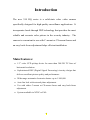
1
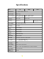
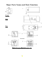
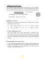
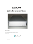
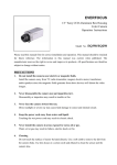
1/3” 520TVL High-Res. Color Camera(350HQ/550)
1/3” 380TVL High-Res. Color Camera(250)
Notice
This manual is presented to users of the EQ series by EverFocus Electronics
Corporation. With years of engineering research, EverFocus has spared no
effort in manufacturing high quality products to users worldwide, and maintains
a policy for continual product improvement. Therefore, EverFocus reserves the
right to revise and improve products, their specifications and documentation
without notice. All product materials: including accessories and components
are provided for your convenience. To keep your EQ Series working at its
optimal level, strictly follow the instructions within this manual. EverFocus is
not responsible for any damages resulting from inappropriate operation.
ii
Table of Contents
Safety Warning ……...……………………………………3
Introduction……………………………………………….4
Specification……………………………………………….5
Major Parts and Their Functions………………….…….6
Installation Instructions……………………………..…. 11
ii
Safety Warning
1. Handle camera with care.
Be careful when handling the camera, do not drop it or subject it
to strong shock or vibration to prevent any damages to it. Do not
disassemble it or place it on an unstable base.
2. Do not install camera near electric or magnetic fields.
Install the camera away from any television, radio transmitter,
magnet, electric motor, transformer, or audio speakers since the
magnetic fields generated from the above named devices will
distort the video image.
3. Do not install camera in a high temperature environment.
Install the camera away from space heaters, stoves, or other heat
generating devices because the high temperatures generated
around these devices can cause deformation, discoloration or
other damages to the camera. Install the camera in an area where
the temperature range remains between 0o to 50 o C (32o to 122o
F).
4. Never aim camera toward the sun whether the unit is in use or
not.
The severe rays of direct sunlight or objects that emit extremely
intense rays may cause fatal damage to the sensor and internal
circuit.
5. Cleaning
Do not touch the surface of the CCD sensor directly. Use a soft
cloth to remove any dirt from the camera body. Use a lens
tissue or cotton tipped applicator and ethanol to clean the CCD
sensor and/or the camera lens. Always replace the cover cap on
the lens mount, when the camera is not in use.
3
Introduction
The new 350 HQ series is a solid-state color video camera
specifically designed for high quality surveillance applications. It
incorporates break through DSP technology that provides the most
reliable and accurate color picture in the security industry. The
camera is convenient to use with C-mount or CS-mount lenses and
an easy back-focus adjustment helps efficient installation.
Main Features:
• 1/3” color CCD pickup device for more than 380/520 TV lines of
horizontal resolution.
• Sophisticated DSP (Digital Signal Processing) circuitry design that
delivers excellent picture quality and performance.
• Wide range automatic electronic shutter: up to 1/100,000.
• Auto line lock with external phase adjustment.
• Use with either C-mount or CS-mount lenses and easy back-focus
adjustment
• System available in NTSC or PAL.
4
Specifications
Model
250
350HQ
550EX
Pickup Device:
1/3” interline transfer color CCD
Video Format:
NTSC / PAL
Picture Element:
NTSC: 510(H) x 492(V)
PAL: 500(H) x 580(V)
NTSC: 768(H) x 494(V)
PAL: 752(H) x 582(V)
Horizontal
Resolution:
380TV lines
520TV lines
Sensitivity:
0.5lux/F=1.2
0.5lux/F=1.2
Video Output:
BNC VBS 1.0Vp-p, 75ohm
S/N Ration:
Over 48dB
Electronic
Shutter:
Back Light
comp.:
Auto Gain
Control:
Auto White
Balance:
Up to 1/100,000
ON/OFF switch
ON/OFF switch
Digital auto tracing
Fluorescent:
ON/OFF switch
Auto IRIS:
Switch-able Video Drive or Direct Drive
Sync. Mode:
1.0lux color, 0.15lux
monochrome/F=1.2
1. Line-Locked with LL on
2. Internal Sync. With LL off
Gamma
Correction:
>0.45
Power Source:
12VDC/24VAC; 90~265VAC
Dimension
51(W) x 57(H) x 140.2(D)mm;2(W)x 2.25(H)x5.52(D)inch
Operating
Temperature:
Power
Consumption:
0°~50°,20%~80%
5W max.
5
Major Parts Names and Their Functions
1
3
Front
Side
7
Top
12(optional)
Rear (EQ series) Rear(EQ series” A”)
6
1. Focal Length Adjustment Ring
Use this ring to adjust the appropriate focal length according to
the lens type. Rotate the ring clockwise for a CS-mount lens;
rotate the ring counterclockwise for a C-mount lens. The
factory setting is C-mount.
2. Lens Mount
Used to mount an appropriate C-mount or CS-mount lens.
3. Locking Screw
Use the locking screw to set the focal length.
4. Lens Connector (4 pin socket)
Connect to the lens plug of the auto iris lens.
5. Control Switches
There are six (6) control switches located on the sideboard.
These are used to set the special features. The switches in order
are for Flicker less, Back Light Compensation, Electronic
Shutter, Automatic Gain Control, Line-Lock and Auto Iris Lens
type.
Fluorescent On/OFF
This is a function compensates for the flickering images that can
occur in fluorescent light conditions. When filming images in
fluorescent lighting, turn on the Fluorescent function; the default
setting is off.
BLC (Back Light Compensation) On/Normal
When BLC is turned on, the AGC, ES and IRIS operating point is
determined by averaging over the center area instead of entire fieldof-view, so that a dimly-lit foreground object in the center area can
be clearly distinguished from brightly-lit backgrounds. BLC should
not be used unless it is needed to compensate for back-lighting.
The default setting is Normal.
7
ES (Electronic Shutter) Off/On
ES ON: The camera continuously adjusts the shutter speed from 1/60
(NTSC),1/50 (PAL) second to 1/100,000 second according to the
luminance conditions of the scene.
ES OFF: The shutter speed is fixed at 1/60 (NTSC), 1/50 (PAL)
second. Place ES in the off position, when auto iris lens are used or
flicker is observed under extremely bright fluorescent lighting. In all
other lighting, keep ES in the on position for optimum performance.
The default setting is ON.
AGC (Automatic Gain Control) Off/On
AGC ON: The sensitivity increases automatically when light is low.
AGC OFF: A low-noise picture is obtained under a low light
condition. The default setting is ON.
LL (Line-Lock) Off/On
Use this switch to select the sync mode between Internal Sync.(LL
off) and Line-Lock (LL on). To synchronize the camera to the
internal time base, set the line-lock in the off position. By setting the
line-lock on, the camera’s vertical synchronization can be driven by
the AC signal in the power lines.
Note: The cameras feature AC line lock for external
synchronization. Using the AC power frequency (60Hz) is
possible but not available when using DC or other
operation power such as NTSC in 50Hz or PAL in 60Hz
power system.
8
VD/DD (Auto Iris lens Type)
For video drive auto iris lens, please set the switch to VD. For direct
drive iris lens, set the switch to DD. The default setting is DD. Wire
the lens cable to the lens connector according to the following table.
Pin1 Pin2 Pin3 Pin4
Lens Connector
Video Drive +12V GND VD-IRIS GND
1
Direct Drive
2
Cnt-Cnt+ Drv+ Drv-
6. IRIS Level Control
Brightness Level can be adjusted from the IRIS level VR while
using the direct drive lens.
2•
Turn
1•
Turn
counterclockwise
clockwise
to
to
L
H
for
for
a
a
darker
picture.
brighter
picture.
7. V-Phase Adjustment Screw
The vertical phase may require adjustment to synchronize the
vertical phase of the camera with other camera in the system when
it is to be used in the line-lock sync mode. Make the adjustment
when the vertical phase of the camera does not match with other
cameras.
8. Mounting Base and Fixing Screws
To use when the mounting bracket is required while mounting the
camera. The mounting base can be attached to either the top or the
bottom of the camera; fix the mounting base onto the camera by
using the 4 supplied fixing screws.
9
9. Video Output Connector
BNC VBS 1.0 Vp-p, 75ohm
1 Power Cable (EQ series)
2 DC12V/AC24V Screw Terminals (EQ series “A”)
3 Audio Output(optional):Connect with an audio device, RCA
connector
10
Installation Instructions
1) Remove the cap cover from the top of the lens mount.
2) To attach a C-mount/CS-mount lens, turn the focal length
adjustment ring to the appropriate position. Note: If a C-mount
lens is used, please make sure the focal length adjustment ring
is set at C position before fixing the lens.
a)
Screw the lens firmly onto the lens mount. Insert the lens plug
in the lens connector if the auto iris lens is used.
b)
c)
Tighten the locking screw.
Connect the video output of the camera to a color monitor or
other video device through a 75 ohm type coaxial cable with
BNC female connector.
d)
e)
Plug the power cord to the outlet.
Once the image appears on the monitor, adjust the focus and
diaphragm of the lens to obtain the best picture.
If the subject is not in focus when adjusting focus of lens, do
focal length adjustment as following:
f)
i) Loosen the locking screw of the focal length adjustment ring.
ii) Take picture of subject at a distance more than 20m away
from the camera.
iii) Rotate the focal length adjustment ring to bring the subject
in focus.
iv) Tighten the locking screw while the adjustment is completed.
11
EverFocus Electronics Corporation
Home Office:
12F, No.79 Sec. 1 Shin-Tai Wu Road, Hsi-Chih, Taipei, Taiwan TEL: +886-226982334 FAX: +886-2-26982380 www.everfocus.com.tw
USA Office:
2445 Huntington Drive, San Marino, CA 91108, U.S.A. TEL: +1-626-844-8888
FAX: +1-626-844-8838 www.everfocus.com
European Office:
Albert-Einstein-Strasse 1 D-46446 Emmerich, Germany TEL: 49-2822-9394-0
FAX: 49-2822939495 www.everfocus.de
China Office:
Room 609, Technology Trade Building, Shandgdi Information Industry Base,
Haidian District, Beijing,China TEL: +86-10-62971096 FAX: +86-10-62971432
www.everfocus.com.cn
Japan Office:
1809 WBG MARIBU East 18F, 2-6 Nakase.Mihama-ku. Chiba city 261-7118, Japan
TEL : +81-43-212-8188 FAX : +81-43-297-0081 www.everfocus.com
P/N: MQ35G00900
12
13