1
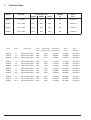
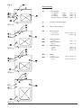
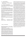
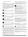
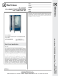
USER MANUAL ELECTRIC CONVECTION STEAMER air - o - steam® Series 57 6 GN 1/1 10 GN 1/1 20 GN 1/1 20 GN 2/1 GB DE FR English Deutsch Français Page 1 - 21 Page 1 - 22 Page 1 - 24 I - 450 - BE, I - 432 - B, I - 456 - BF I - 450 - BE DOC. NO. 5958 785 01 EDITION 2 J 0107 1. Technical data Model Capacity 5711-3 6 x 1/1GN 715 890 5712-3 10 x 1/1GN 941 5714-3 20 x 1/1GN 5717-3 20 x 2/1GN Model Version Dimensions mm Height Width Depth Weight kg Noise level 784 120 < 70 dB (A) 890 928 170 < 70 dB (A) 1748 890 928 250 < 70 dB (A) 1748 890 1243 340 < 70 dB (A) Rated voltage Control voltage 2 Rated voltage Nominal input heating elements heating elements Rated Wiring output diagram Nr. 5711-3 5711-3 5711-3 VI VII VIII, X 3N AC 400V 50Hz 3N AC 400V 50Hz 3N AC 400V 50Hz 230V 230V 230V 230V 230V 230V 9 000W 9 000W 9 000W 9 300W 9 300W 9 300W 883 606-3 884 607-3 884 608-3 5712-3 5712-3 5712-3 VI VII VIII, X 3N AC 400V 50Hz 3N AC 400V 50Hz 3N AC 400V 50Hz 230V 230V 230V 230V 230V 230V 17 000W 17 000W 17 000W 17 300W 17 300W 17 300W 883 622-3 883 619-3 883 620-3 5714-3 5714-3 5714-3 VI VII VIII, X 3N AC 400V 50Hz 3N AC 400V 50Hz 3N AC 400V 50Hz 230V 230V 230V 230V 230V 230V 34 000W 34 000W 34 000W 34 500W 34 500W 34 500W 883 622-3 883 619-3 883 620-3 5717-3 5717-3 5717-3 VI VII VIII, X 3N AC 400V 50Hz 3N AC 400V 50Hz 3N AC 400V 50Hz 230V 230V 230V 400V 400V 400V 48 000W 48 000W 48 000W 48 900W 48 900W 48 900W 883 615-3 884 609-3 884 617-3 I-450-BE Fig. 5 Connections EZ = Current supply 5 x 2,5mm² 5 x 6mm² 5 x 10mm² 2x (5 x 10mm²) PG21 PG29 PG36 2x PG29 10 = Funnel for descaling agent ME = Interior cavity venting SW = Steam release ø 40 mm 40 x 80 mm (5711 - 3) (5712 - 3) (5714 - 3) (5717 - 3) 5711 - 3 WA1 = WA2 = WA = 5712 - 3 WZ1 = WZ2 = Water discharge R 1 1/4" Water discharge Rp 3/4" Water discharge R 1 1/4" R 1 1/4" Rp 1 1/2" Water R 3/4" Softened water R 3/4" (5711 - 5714 - 3) (5717 - 3) (5711 - 3) (5711 - 3) (5712 - 3) (5714 - 3) (5717 - 3) (5711 - 5717 - 3) (5711 - 5717 - 3) 5714 - 3 5717 - 3 I-450-BE 3 a very irregular floor the mounting of a wheel-guided roll-in guide is recommended for a perfect exchange of all trolleys (available also as accessory). INSTALLATION INSTRUCTIONS INDEX 1. 2. 2.1. 2.1.1. 2.1.2. 2.2. 2.2.1. 2.3. 2.3.1. 2.3.2. 2.3.3. 2.4. 2.4.1. 2.4.2. 2.5 2.6. 2.7. 2.8. 3. 4. 4.1. 4.2. 4.3. 4.4. 5. Unit identification 2 Installation and connection 4 Installation 4 Table top models 4 Free-standing floor units 4 Electrical connection 4 Connection to the power mains 4 Water connection 4 Indication for units with steam generator and connection to drinking water 4 Solid substances 5 Dissolved substances 5 Connection to the drainage system 5 Open connection to the drainage system 5 Fixed connection to the drainage system 5 Connection to the exhaust gas discharge 5 General information 6 Procedure in case of malfunction 6 Proper handling and maintenance 6 Safety recommendations 6 Operating instructions 7 Control panel (fig.1 - 4) 7-10 Operating instructions - version VI 11 Operating instructions - version VII 12 Operating instructions - version VIII 13 Operating instructions - version X 16 Cleaning and maintenance 20 2. Installation and connection 2.1. Installation 2.1.1. Table models 5711-3, 5712-3 The following is to be observed: - An even and level installation room. - Keep a distance to heat dissipating units. - No direct steam and heat influence from neighbouring units. - Alignment of the unit by means of the height adjustable feets, unit must be preheated. - Fastening with the enclosed foot plates (screw in or glue). For installation as a group keep a distance of at least 500 mm between the units. 2.1.2. Free-standing floor units 5714-3, 5717-3 - even and level installation room. - alignment of the unit by means of the height-adjustable feets. Unit must be preheated. - uniform clearance. - trolley must be insertable perfectly. - alignment of the trolley by inserting spacers between trolley frame and wheel (available also as accessory). - when installing several free-standing units or in case of 4 When positioning the free-standing models against a wall/niche a distance of at least 500 mm is recommended for installation and service reasons. 2.2. Electrical connection See page 6: “Connection of the air-o-steam® units to the power mains” - Before connecting the unit check type of power supply and voltage available with the data plate. - Connection according to wiring diagram; wiring diagram is to be found inside the unit. - Connection shall be carried out by authorized personnel only. - Respect the regulations, local prescriptions of the electric power plant. Take particular care: - During installation the unit must be secured sufficiently and be equipped with a cut-off device (all-pole cut-off ≥ 3 mm). Connect an equipotential cable - situated next to the electrical connection - to the equipotential screw. - The unit may be used only with the prescribed safety devices. (Protection category I). - Use only flexible connection cables - H07 RN-F. 2.2.1. Electric cable connection To connect the supply cable to the terminal block of the appliance, proceed as follows: - Loosen the two screws on the cover of the connection box to be found on the bottom of the appliance. - The box cover of the terminal block swings open downwards. - Pass the connection cable through the corresponding cable grip in the lid. - Connect the different leads of the cable according to the wiring diagram and tighten the cable grip. - Replace the cover and tighten the relative fastening screws. 2.3. Water connection - Hose connection 1/2" pressure tight, cap nut 3/4". - Insert a waste sieve on site. Sieves are installed as standard equipment before the valve. - Connection has to be effected to softened cold water. - Max. mains pressure 10 bar, cold water. 2.3.1. Indication for units with steam generator and connection to drinking water - Steam generator is supplied with drinking water. - Water quality is important for: • • • - function, durability - heating element, energy consumption. Criteria concerning the water quality are the solid and the dissolved substances. I-450-BE 2.3.2. Solid substances Solid substances are e.g. sand or residues from the piping; to avoid these materials to deposit: insert a filter. 2.3.3. Dissolved substances Dissolved substances are gases and salts. Gases If the gases are nitrogen, oxygen and carbon dioxide it does not create any problems. If on the contrary the carbon dioxide is dissolved in an aggressive form as carbonic acid, the following measures (filter, degas) are to be foreseen to avoid corrosion. Salts Salts dissolved in water influence the water quality as hardening agent or non-hardening agent. Hard and/or very saliferous water will harm the steam generator’s operation. The relevant standard for the water hardness is the degree of German hardness (°d). It is classified as follows: 0 - 7°d softened water 7 - 14°d medium hard water 14 - 21°d hard water more - 21°d very hard water Only softened water (max. 5 - 7°d) ensures a trouble free operation of the steam generator. A hardness too low (below 5°d) can provoke corrosion inside the steam generator and the unit, increased hardness will lead to the calcification of the heating elements and to break-down due to the resulting heat accumulation, as well as to the calcification of the steam generator and the unit. For a troublefree operation of the steam generator the following water quality is recommended: 1. 2. 3. 4. Hardness: Chloride: Sulphide: Heavy metals: 5 - 7° d no more than 150 - 250 mg/l no more than 400 mg/l iron less than 0,10 mg/l manganese less than 0,05 mg/l copper only traces 5. Total saline content no more than 400 - 600 mg/l In case the drinking water does not comply with these indicative values, it must be adjusted - best directly before entering the steam generator - to the recommended values. For harder water the installation of an ion exchanger is recommended, which must be regenerated from time to time with cooking salt. By adding normal water it is possible to reach the necessary hardness of 5° d. The usual injection of phosphate to avoid lime deposits and corrosion inside the piping is harmless if the introduced quantity does not exceed 5 mg P2O5/l (2,5 mg phosphoric acid anhydride P4O10) according to the relevant drinking water regulations. In case this value will be exceeded considerably for whatever reason, the residues may have a negative influence on the steam generator and the unit. Using not softened water a regular descaling is absolutely necessary (see more precise explanations given in the instruction manual). The descaling intervals depend on the water hardness and the daily operation hours; therefore it is not possible to provide precise indications. I-450-BE Conversion to other degrees of water hardness: 1°d = 0,1783 mmol/l = 1,79°F (France) = 1,25°e (Great-Britain) = 17,9 ppm (USA) 2.4. Connection to the drainage system Observe the prescriptions of the national standards. 2.4.1. Open connection to the drainage system The connection of the drainage pipe is foreseen at the centre of the unit. The following is to be observed: • • • • • • Temperature resistant hose/pipe. Install with a constant direct slope (approx. 3%) without any buckles. The waste water outlet must be outside the positioning surface of the unit (respect a distance of at least 1 m away from the unit. Formation of waste air/steam!). The waste water outlet must be approx. 30 mm above the water level of a syphon drain or trough. Never reduce the diameter of the discharge pipe. Maintain the diameter of the connection sleeve. In case the unit is installed as part of a group, each unit must be connected to a separate drain pipe into an open funnel or syphon drain. 2.4.2. Fixed connection to the drainage system • • • • - - Waste water connection sleeve of unit: R 11/4" and R 3/4" (5711 - 3) R 11/4" (5712/14 - 3) Rp 11/2" (5717 - 3) Waste water piping preferably as rigid pipe Install with a constant slope (approx. 3%) Installation of a rigid pipe: Sleeve joint nipple: R 11/4" - 34 mm additional Rp 11/2" - R 11/4" Rigid PE-pipe 34 x 2 (5711/12/14 - 3) (5717 - 3) Important ! In case of a fixed connection to the drainage system it is absolutely necessary to install a venting pipe between unit and syphon drain. If this venting pipe is not part of the unit it is available as accessory to be ordered separately. 2.5. Connection to the exhaust gas discharge - The installation underneath an extraction hood is recommended. - A waste air quenching system is installed inside the unit as standard equipment. It is controlled by means of a thermostat, this means it is activated and deactivated automatically. - This system prevents the escape of vapours and the water consumption is reduced to a minimum. - In the version VII,VIII and X the waste air quenching system can be activated or deactivated. Installing the appliance under a steam extraction hood, saves on water. - It is forbidden to connect the pipe of the waste air quenching system directly to that of the extraction hood. 5 2.6. General information - Do not block the vapour escape. - Do not block or cover the safety device (steam release safety valve). - The units are designed for unattended operation. 2.7. Procedure in case of malfunction In case of malfunction disconnect the unit immediately and call for the after-sales-service. Any servicing or reparation of malfunction is to be carried out by authorized qualified technicians only. 2.8. Proper handling and maintenance Only in case of proper handling according to the regulations of this installation instructions, the operating instructions (manual) and the indications concerning cleaning and care as well as a regular maintenance by an authorized technician we will be able to guarantee perfect operation and operation safety according to our sales and delivery terms. This is equally valid for the regulations of the laws in force concerning unit safety and the prevention of accidents. Therefore we recommend the stipulation of a maintenance contract. Only use original spare parts ! To maintain the operational value of your unit and to avoid malfunctions we recommend a regular maintenance according to the check-list. The authorized after-sales-service trained for this kind of appliance guarantees maximum service for your unit. Regular maintenance (see checklist) obviously depends on the frequency of operation; the recommended intervals are: Operation: up to 2 hours a day between 2 to 6 hours a day more than 6 hours a day maintenance every 12 months maintenance every 6 months maintenance every 4 months 3. Safety recommendations Before operating the appliance, it must be installed according to the assembly instructions and connected by an authorised technician. The appliance should not be switched on until the user has been instructed on how to operate it. The appliance may only be used by trained personnel. It has been officially approved for cooking food in commercial kitchens and food processing businesses only. Closed containers such as tins, jars, bottles, tubes, etc. may not be heated in the appliance as they could explode with the consequent risk of injuring persons or damaging the appliance. When using the appliance in the Steam, Steam 1 or Steam 2/Regenerate modes, the door should first of all be opened to the waiting position. Only after the steam has escaped through the slits created around the door, may the latter be fully opened. When working with this appliance, hygiene standards (HACC) must be strictly 6 observed. When preparing food to be cooked at a low temperature, for example, a stage lasting 10 - 15 minutes with a cooking temperature of ≥ 150°C must be inserted, observing the process carefully. In this way any bacteria on the surface of the food to be cooked will be destroyed. During preparation of foods to be cooked, it should also be checked that utensils are absolutely clean, in order to avoid any contamination inside the actual food. Should these instructions not be respected, the manufacturer cannot guarantee that the food will be cooked perfectly from a hygienic and sanitary point of view. No objects such as GN containers, pans, cloths, etc. should be placed on the appliance when it is in use. When in operation, avoid touching glass or metal surfaces as there is the risk of injury due to the high cooking temperatures. The appliance must not be cleaned with any high-pressure cleaning device (see further instructions under paragraph ”Cleaning and care”). To clean the cooking chamber and stainless steel parts, only use a special cleaning agent recommended for this type of appliance (see further instructions under paragraph ”Cleaning and care”). To remove any scale from the steam generator, only use a descaling product specially developed for this purpose (see further instructions under paragraph ”Cleaning and care”). In the event of malfunctioning or failure, switch off the appliance. If the self-diagnosis on the electric controls does not identify the fault or if the panel or covering elements would have to be removed in order to be able to eliminate the trouble, contact the nearest service centre. The appliance must not be switched on again until the fault has been mended. Some faults or malfunctioning may also be caused by faults in the electricity supply or by impurities in the water supply or drainage system. The manufacturer of the appliance cannot be held liable for this type of fault. The user should also have these points checked regularly by an authorised service centre. To guarantee that the appliance is in proper working order, periodic maintenance and checks by an authorised technician are necessary. Such technicians must be trained by the manufacturer and observe the laws and standards in force in connection with their work. It is therefore advisable to take out a maintenance contract. Parts and components must not be replaced with other than original spare parts. In compliance with our terms of sale and delivery, perfect and safe operation of the appliance is only guaranteed if it has been handled and used correctly, operated according to the operating instructions, looked after, cleaned and regularly overhauled by technical personnel or by the service centre. I-450-BE 4. Operating instructions Version VI 1 ON/OFF switch 11 Hot air 12 Steam 13 Steam 1 14 Steam 2/regeneration 17 Programming the temperature of the cooking chamber 18 Programming the duration of the cooking cycle 28 Warning of scale build-up in the steam generator 29 Door safety 30 Steam generator level gauge 31 Low temperature steam Fig. 1 I-450-BE 7 Version VII 1 ON/OFF switch 11 Hot air 12 Steam 13 Steam 1 14 Steam 2/regeneration 17 Programming the temperature inside the cooking chamber 18 Programming the duration of the cooking cycle 19 Programming the core temperature 25 Waste steam quenching system 26 Manual humidification 28 Warning of scale build-up inside the steam generator 29 Door safety 30 Steam generator level gauge 31 Low temperature steam 32 Fan speed selection switch Fig. 2 8 I-450-BE Version VIII 1 ON/OFF switch 3 Start/Stop 5 Cook Step 6 Fan speed selection 7 Cook & Hold 8 Intermittant fan operation 9 ECO-Delta Cooking 10 Programming the starting time of the cooking cycle 11 Hot air 12 Steam 13 Steam 1 14 Steam 2/regeneration 17 Programming the temperature inside the cooking chamber 18 Programming the duration of the cooking cycle 19 Programming the core temperature 23 Steam generator discharge 24 Clean programme 25 Waste steam quenching system 26 Manual humidification 27 Steam release valve of the cooking chamber 28 Warning of scale build-up inside the steam generator 29 Door safety 30 Steam generator level gauge Fig. 3 I-450-BE 9 Version X 1 ON/OFF switch 2 Mode “PROG/AUTO” 3 Start/Stop 4 Programme selection 5 Cook Step 6 Fan speed selector 7 Cook & Hold 8 Intermittent fan operation 9 ECO-Delta Cooking 10 Programming the starting time of the cooking cycle 11 Hot air 12 Steam 13 Steam 1 14 Steam 2/regeneration 15 Indication of the actual temperature value 16 Regulation of the moisture degree 17 Programming the temperature inside the cooking chamber 18 Programming the duration of the cooking cycle 19 Programming the core temperature 20 CLEAR ENTRY 21 MEMORY 22 PROGRAM 23 Emptying the steam generator 24 Clean programme 25 Waste steam quenching system 26 Manual humidification 27 Steam release valve of the cooking chamber 28 Warning of scale build-up in the steam generator 29 Door safety 30 Steam generator level gauge Fig. 4 10 I-450-BE 4.1. Control panel - version VI MAIN SWITCH (Fig.1 No.1) The main switch is situated on the upper part of the control panel and is used to switch the appliance on or off. When the marking of the knob points to "0" the appliance is switched off. When selecting the cooking programmes mentioned below the appliance is switched on automatically. The indicator light above the switch lights up. To switch off the appliance simply turn the main switch back to position ”0”. The indicator light goes out. The five cooking programmes are activated by means of a programme selection switch. HOT AIR (Fig.1 No.11) In this position only the heating of the cooking chamber is activated, which means just hot-air operation. STEAM (Fig.1 No.12) In this position only the steam generator heating elements are activated, which means just steam operation (100°C). STEAM 1 (Fig.1 No.13) In this position the heating of the cooking chamber is activated as well as the steam generator heating elements in the proportion of 75% hot air and 25% steam. 10 minutes. In the ”STEAM” cooking mode, the temperature is automatically limited to 100 °C. In the ”STEAM 1" and ”STEAM 2” cooking modes, the programmable maximum temperature is 250° C. In the ”LOW-TEMPERATURE STEAM" cooking mode, the programmable temperature goes from 30° to 99° C. ACTUAL COOKING TIME (Fig.1 No.18) Programming the desired cooking time. The time scale is divided into three different graduations : Range from 1 - 20 min.: This enlarged range in 1-minute stages is provided for short term cooking. Range from 20 - 120 min.: This range in 4-minute stages is provided for long term cooking. Range ¥: This sign of infinity indicates continuous operation. In this position the appliance is preheated or is working in the “stand-by” operation. By turning the knob, the timer is activated and the cooking process starts, if the desired cooking programme and temperature has been preset. During the course of cooking process the green indicator light above the knob lights up. As soon as the cooking time is over, the indicator light goes out and an audible signal is activated. Three circular indicator lights, placed in the lower part of the control panel, are indicating the following control functions. WARNING OF SCALE BUILD-UP IN THE STEAM 2 - REGENERATION (Fig.1 No.14) In this position the heating of the cooking chamber is activated as well as the steam generator heating elements in the proportion of 50% hot air and 50% steam. Low temperature steam, vacuum-cooking (Fig.1 No.31) In this position only the steam generator heating elements are activated, which means just steam operation (temperature range between 30°C and 99 °C). STEAM GENERATOR (Fig.1 No.28) When the indicator light relating to the symbol comes on, this means that there is a build-up of scale in the steam generator and on the heating elements. Descaling should be carried out as quickly as possible. Detailed instructions for the chemical descaling of the entire system are given in the chapter ”Cleaning and care”. DOOR SAFETY (Fig.1 No.29) If the indicator light relating to this symbol comes on, the door is not closed properly and consequently the ”STEAM” and ”STEAM 1” cooking modes cannot be activated. COOKING CHAMBER TEMPERATURE STEAM GENERATOR LEVEL GAUGE (Fig.1 No.17) Setting of the required temperature inside the cooking chamber. The temperature may be set anywhere between 50° and 300° C. The markings on the knob allow the approximate regulation of the temperature value, while the luminous digital indication (display) above the knob allows a precise regulation. During the process of programming the temperature value is blinking. If no further change is made, after 3 seconds the display will indicate the temperature value actually measured by the temperature sensor inside the cooking chamber, thus enabling a constant control of the actual temperature inside the cooking chamber. In the "HOT AIR" cooking mode, the programmable maximum temperature is 300° C. In this case the temperature range between 250° and 300°C is limited to (Fig.1 No.30) The indicator light relating to the steam generator symbol blinks whenever the water in the steam generator does not cover the safety level mark. If the indicator light up continously, this means that the steam generator is still being filled with water, the heating elements, however, can be activated. The steam generator is ready for use. When the indicator light goes out, this means that the water level inside the steam generator is correct and there is no need to top up. I-450-BE 11 4.2. Control panel - version VII MAIN SWITCH (Fig.2 No.1) The main switch is situated on the upper part of the control panel and is used to switch the appliance on or off. When the marking of the knob points to “0” the appliance is switched off. When selecting the cooking programmes mentioned below the appliance is switched on automatically. The indicator light above the knob lights up. To switch off the appliance simply turn the main switch back to position ”0”. The indicator light goes out. The five cooking programmes are activated by means of a programme selection switch. HOT AIR (Fig.2 No.11) In this position only the heating of the cooking chamber is activated, which means just hot air-operation. STEAM (Fig.2 No.12) In this position only the steam generator heating elements are activated, which means just steam operation (100 °C). STEAM 1 (Fig.2 No.13) In this position the heating of the cooking chamber is activated as well as the steam generator heating elements in the proportion 75% hot air and 25% steam. STEAM 2 - REGENERATION (Fig.2 No.14) In this position the heating of the cooking chamber is activated as well as the steam generator heating elements in the proportion 50% hot air and 50% steam. Low temperature steam, vacuum-cooking (Fig.2 No.31) In this position only the steam generator heating elements are activated, which means just steam operation (temperature range adjustable between 30°C and 99 °C). COOKING CHAMBER TEMPERATURE (Fig.2 No.17) Setting of the required temperature inside the cooking chamber. The temperature may be set anywhere between 50° and 300° C. The markings on the knob allow the approximate regulation of the temperature value, while the luminous digital indication (display) above the knob allows a precise regulation. During the process of programming the temperature value is blinking. If no further change is made, after 3 seconds the display will indicate the temperature value actually measured by the temperature sensor inside the cooking chamber, thus enabling a constant control of the actual temperature inside the cooking chamber. In the “HOT AIR” cooking mode, the programmable maximum temperature is 300° C. In this case the temperature range between 250° and 300°C is limited to 12 10 minutes. In the ”STEAM” cooking mode, the temperature is automatically limited to 100 °C. In the ”STEAM 1" and ”STEAM 2” cooking modes, the programmable maximum temperature is 250° C. In the ”LOW-TEMPERATURE STEAM” cooking mode, the programmable temperature goes from 30° to 99° C. ACTUAL COOKING TIME (Fig.2 No.18) Programming the desired cooking time. The time scale is divided into three different graduations : Range from 1 - 20 min.: This enlarged range in 1-minute stages is provided for short term cooking. Range from 20 - 120 min.: This range in 4-minute stages is provided for long term cooking. Range ¥: This sign of infinity indicates continuous operation. In this position the appliance is preheated or is working in the “stand-by” operation. By turning the knob, the timer is activated and the cooking process starts, if the desired cooking programme and temperature has been preset. During the course of cooking process the green indicator light above the knob lights up. As soon as the cooking time is over, the indicator light goes out and an audible signal is activated. If the cooking process is carried out by using the core temperature sensor, the timer must be in the “0” position. CORE TEMPERATURE (Fig.2 No. 19) In this cooking process the cooking time is determined by the set core temperature. For this operation it is necessary to set the timer to the “0” position. By turning the knob to the right the required core temperature can be increased up to 99°C maximum. By turning the knob to the left, the temperature is lowered, with a programmable temperature value of 0°C minimum. During the programming stage the set temperature value is blinking on the display above the knob. If no further change is made, after 3 seconds the display will indicate the temperature value actually measured by the core temperature sensor, thus enabling a constant control of the roast during the entire cooking process. REDUCED FAN SPEED (Fig.2 No. 32) When pressing this button the indicator light above the symbol lights up. If the appliance has not yet been started and therefore the fan is not yet in operation, the fan motor will automatically operate at reduced speed after starting the cooking process. If on the contrary the fan motor has been started at high speed, it will be interrupted shortly (approximately 15 seconds), after which the motor automatically starts at reduced speed. To operate the appliance with normal fan speed, just press this button again. The indicator light goes out and the motor automatically changes to normal speed. Note: when the fan reduced speed is enabled, the hot air power gets automatically reduced to 50% : EMPTYING THE STEAM GENERATOR (Fig.2 No.23) The appliance is fitted with a motor-operated discharge valve. Under normal conditions it is closed and this is shown by I-450-BE the indicator light above the symbol going out. Upon pressing the button the valve opens so that the water inside the steam generator can drain off. This operation is shown by the relative indicator light coming on. Once the boiler has been drained the button must be pressed again to close the valve. WASTE STEAM QUENCHING SYSTEM (Fig.2 No.25) This button can be used to activate or deactivate the thermostatic waste steam quenching system in all the cooking modes. If the air-o-steam® is placed under a steam extraction hood, the steam need not be condensed by spraying cold water into the waste tube. This saves on water. Upon pressing this button, the relative indicator light above the symbol starts blinking, showing that the steam condensation device is deactivated. By pressing the button again, the system is re-activated in normal condition and depending on whether water is being injected or not, the relative indicator lights up constantly or goes out. MANUAL HUMIDIFICATION (Fig.2 No.26) This button may be used to increase the degree of humidity inside the cooking chamber by introducing water. The water input time is limited to about 5 seconds. The relative indicator light is on during water input. The degree of humidity in the cooking chamber may be altered to individual requirements by pressing this button several times. Three circular indicator lights, placed in the lower part of the control panel, are indicating the following control functions. WARNING OF SCALE BUILD-UP IN THE STEAM GENERATOR (Fig.2 No.28) When the indicator light relating to the symbol comes on, this means that there is a build-up of scale in the steam generator and on the heating elements. Descaling should be carried out as quickly as possible. Detailed instructions for chemical descaling of the entire system are given in the chapter ”Cleaning and care”. DOOR SAFETY (Fig.2 No.29) If the indicator light relating to this symbol comes on, the door is not closed properly and consequently the ”STEAM” and ”STEAM 1” cooking modes cannot be activated. STEAM GENERATOR LEVEL GAUGE (Fig.2 No.30) The indicator light relating to the steam generator symbol blinks whenever the water in the steam generator does not cover the safety level mark. If the indicator lights up continously, this means that the steam generator is still being filled with water, the heating elements, however, can be activated. The steam generator is ready for use. When the indicator light goes out, this means that the water level inside the steam generator is correct and there is no need to top up. I-450-BE 4.3. Control panel - version VIII ON/OFF SWITCH (Fig.3 No.1) The ON/OFF switch is used to switch the appliance and controls on or off. To switch the appliance on, lightly press the button; to switch off keep the button pressed down for about 3 seconds. This time delay avoids accidental switching off during a cooking cycle. When the appliance is switched off, this is indicated by the green indicator light above the button going out. When the appliance is switched on it lights up. Note: upon switching off the appliance, wait at least 5 seconds before switching on again. COOK-STEP (Fig.3 No.5) With this COOK-STEP storage, it is possible to divide a cooking cycle into two different sequences: e.g. browning and finishing the cooking of the roast. The two COOKSTEPS are indicated by the two-coloured indicator lights. The lighting up of a red indicator light indicates, that the relevant COOK-STEP is just being programmed or that it is already working. The other STEP which actually is not in operation is shown by a green indicator light. The first COOK-STEP is always activated automatically in the neutral position of the control, which is indicated by the lighting up of the left indicator light in red and the right indicator light, symbolizing the second cooking stage, in green. As soon as the first COOK-STEP is memorized (e.g. cooking chamber temperature in the hot air mode and a certain time for the initial roasting stage), it is possible to activate the second stage by pressing the button and then proceed with a new programming (e.g. cooking chamber temperature in a combination mode and a certain cooking time for the final roasting) . START STOP START/STOP (Fig.3 No.3) After having selected all data necessary for the cooking process, such as temperature, cooking time, cooking mode and fan speed, the cooking process may be started using the ”START/STOP” button. The relative yellow indicator light comes on. The cooking cycle may be interrupted by pressing the button for more than 3 seconds. HOT AIR (Fig.3 No.11) In this position only the heating of the cooking chamber is activated, which means just hot-air operation. STEAM (Fig.3 No.12) In this position only the steam generator heating elements are activated, which means steam operation between 30 - 100°C. 13 STEAM 1 (Fig.3 No.13) In this position the heating of the cooking chamber is activated as well as the steam generator heating elements in the proportion of 75% hot air and 25% steam. STEAM 2 - REGENERATION (Fig.3 No.14) In this position the heating of the cooking chamber is activated as well as the steam generator heating elements in the proportion of 50% hot air and 50% steam. INTERMITTENT FAN OPERATION (Fig.3 No.8) Intermittent fan operation is obtained in this position, i.e. the fan starts and stops at programmed intervals. This intermittent control is activated when the regulator stops the heating of the cooking chamber; i.e. when the set temperature inside the cooking chamber is reached. This intermittent control does not depend on the programmed fan speed. During the heating stage, the fan control is not activated. When working with this version, the indicator light above the button comes on. PROGRAMMING COOKING START TIMES COOK AND HOLD (Fig.3 No.7) This patented low temperature cooking programme is recommended for ”Hot-air and Steam” cooking modes. Upon pressing the ”COOK & HOLD” button, the relative indicator lights above these buttons start blinking. If the desired cooking programme is chosen by pressing the ”HOT AIR” or ”STEAM” button, a fixed programme is set with the following sequence: 1.The heating power (hot air or steam) is reduced to 50%. 2.In the same way, the fan rotation speed is also reduced. In addition, the fan works intermittently after the regulated temperature in the cooking chamber has been reached (low temperature range). If this programme is activated, the relative indicator light comes on. The cooking process is switched off automatically once the set time has elapsed. ECO-DELTA COOKING (Fig.3 No.9) For this cooking process, a temperature value between 0°C and 99°C may be selected by which the cooking chamber temperature will be above the product’s core temperature. Upon activating this programme, the indicator light above the button comes on. (Fig.3 No.10) With this function it is possible to memorize a specific time; the appliance automatically comes on and starts the set cooking process once the time set by means of this button has elapsed. While this programme is in operation, the indicator light above the button remains on. After having programmed the cooking time, you have to set the cooking proces you intend to use as in 2nd Cook Step. COOKING CHAMBER TEMPERATURE (Fig.3 No.17) Programming the desired temperature inside the cooking chamber. The temperature may be set anywhere between 30°C and 300°C with hot air, using the knob.The temperature range between 250°C and 300°C is limited to a time of 10 minutes. This enlarged temperature range ensures fast preheating of the empty appliance or a high stand-by temperature ready for loading the food. During the programming stage the set temperature appears on the display above the knob. If this value is not changed, the appliance automatically changes to visualize the actually measured cooking chamber temperature. ACTUAL COOKINGTIME POWER STAGE SELECTION (Fig.3 No.6) POWER STAGE 1 High fan speed - 100% heating power. In neutral conditions, i.e. when the electrical circuit is activated, the two indicator lights are off. POWER STAGE 2 Reduced fan speed - 100% heating power. By pressing the button once, the indicator light above the fan symbol comes on. POWER STAGE 3 High fan speed - 50% heating power. By pressing the button a second time, the indicator light above the coil symbol comes on. POWER STAGE 4 Reduced fan speed - 50% heating power. By pressing the button a third time, the two indicator lights (fan and coil) come on. Upon pressing the button again, the two indicator lights go off and the control circuit goes back to its initial position, i.e. in the power stage 1 position. 14 (Fig.3 No.18) Programming the desired cooking time. A cooking time of anywhere between 1 minute and 8 hours may be set by using the relative knob. During the programming stage the set cooking time appears on the display above the knob. Upon activating the cooking process the count-down runs minute by minute and the remaining cooking time appears on the display. Continuous operation is activated by exceeding the setting of 8 hours; ”CONT” appears on the display. Note: selecting a cooking programme which stops the cooking process when the set core temperature is reached, excludes the possibility of programming a cooking time. CORETEMPERATURE (Fig.3 No.19) With this procedure the cooking time depends on the set core temperature of the roast. In fact, apart from the core temperature, the only parameter to be set is the cooking chamber temperature. The required temperature may be set anywhere between 0°C and 99°C by means of the knob. During the programming stage the set core temperature is indicated on the display above the knob. If this value is not changed, the appliance automatically changes to visualize the actually measured core temperature. I-450-BE SPECIAL FUNCTIONS COOKING CHAMBER STEAM RELEASE EMPTYING THE STEAM GENERATOR (Fig.3 No.23) The appliance is fitted with a motor-operated discharge valve. Under normal conditions it is closed and this is shown by the indicator light above the symbol going out. Upon pressing the button the valve opens so that the water inside the steam generator can drain off. This operation is shown by the relative indicator light coming on. Once the boiler has been drained the button must be pressed again to close the valve. VALVE (Fig.3 No.27) The steam release valve usually fitted in this version is motor-operated. It opens automatically by pressing on this button. During the opening stage the relative indicator light above the button blinks. Upon completion of opening, the indicator light stops blinking and remains fixed. To close, just press the button again. During the closing stage, the indicator light blinks and goes out when the valve is fully closed. Three circular indicator lights, placed in the lower part of the control panel, are indicating the following control functions. WARNING OF SCALE BUILD-UP IN THE CLEAN (Fig.3 No.24) The ”CLEAN” programme is a cleaning, not a cooking programme. It should be activated regularly at the end of a working day with the air-o-steam® in order to clean the appliance. To activate this programme, press the button for about 3 seconds, after which the relative indicator light stops blinking and remains on. The steam generator starts heating and the cooking chamber is humidified. After the audible warning signal, a detergent has to be sprayed onto the walls of the cooking chamber including the air baffle sheets. Close the door and press the ”CLEAN” button again. The countdown of the action time for the detergent, i.e. 10 minutes, starts. After this, restart the steam generator and let it operate for another 20 minutes, during which all deposits are removed. The indicator light comes on during the second stage. An acoustic signal is activated at the end of the programme. WASTE STEAM QUENCHING SYSTEM (Fig.3 No.25) This button can be used to activate or deactivate the thermostatic waste steam quenching system in all the cooking modes. If the air-o-steam® is placed under a steam extraction hood, the steam need not be condensed by spraying cold water into the waste tube. This saves on water. Upon pressing this button, the relative indicator light above the symbol starts blinking, showing that the steam condensation device is deactivated. By pressing the button again, the system is re-activated in normal condition and the water input control governed by a thermostat allows the vapours to be condensed. After water input, the relative indicator light comes on. MANUAL HUMIDIFICATION STEAM GENERATOR (Fig.3 No.28) When the indicator light relating to the symbol comes on, this means that there is a build-up of scale in the steam generator and on the heating elements. Descaling should be carried out as quickly as possible. Detailed instructions for chemical descaling of the entire system are given in the chapter ”Cleaning and care”. DOOR SAFETY (Fig.3 No.29) If the indicator light relating to this symbol comes on, the door is not closed properly and consequently the ”STEAM” and ”STEAM 1” cooking modes cannot be activated. STEAM GENERATOR LEVEL GAUGE (Fig.3 No.30) The indicator light relating to the steam generator symbol blinks whenever the water in the steam generator does not cover the safety level mark. If the indicator lights up continously, this means that the steam generator is still being filled with water, the heating elements, however, can be activated. The steam generator is ready for use. When the indicator light goes out, this means that the water level inside the steam generator is correct and there is no need to top up. (Fig.3 No.26) This button may be used to increase the degree of humidity inside the cooking chamber by introducing water. The water input time is limited to about 5 seconds. The relative indicator light is on during water input. The degree of humidity in the cooking chamber may be altered to individual requirements by pressing this button several times. I-450-BE 15 4.4 Control panel - version X ON/OFF SWITCH COOK-STEP (Fig.4 No.1) The ON/OFF switch is used to switch the appliance and controls on or off. To switch the appliance on, lightly press the button; to switch off keep the button pressed down for about 3 seconds. This time delay avoids accidental switching off during a cooking cycle. When the appliance is switched off, this is indicated by the green indicator light above the button going out. When the appliance is switched on it lights up. Note: upon switching off the appliance, wait at least 5 seconds before switching on again. (Fig.4 No.5) With this COOK-STEP storage, a cooking of cycle consisting of six different sequences may be set: e.g. browning, cooking and keeping the food warm. Programming the sequences is described under ”Storage of cooking programmes”. The relative indicator lights have two colours showing the COOK-STEP of the cooking process and the number of programmed COOK-STEPS. If the red indicator light is on, the COOK-STEP is working. All the other programmed sequences which are not in operation are shown by green indicator lights. Indicator lights which are not on, correspond to the unused COOK-STEPS. Changing from one sequence to another is indicated by a buzzer. PROG/AUTO (Fig.4 No.2) The ”PROG/AUTO” button can be used to set automatic operation with all stored data or operation in the programming mode. After having switched on the appliance, the indicator lights to the side of the button start blinking. Pressing the touch pad once sets the ”PROG” mode; the relative indicator light stops blinking and remains on. The indicator light corresponding to the ”AUTO” mode goes out. To change to the ”AUTO” mode, press the button again. The change is shown by the relative indicator light coming on. Note: It is only possible to change to the ”AUTO” mode if a cooking programme has been stored. Operation in the ”AUTO” mode is shown by the relative indicator light above the button coming on. START STOP START/STOP (Fig.4 No.3) After having selected all data necessary for the cooking process, such as temperature, cooking time, cooking mode and fan speed, the cooking process may be started using the ”START/STOP” button. The relative yellow indicator light comes on. This cooking cycle may be interrupted by pressing the button during operation for more than 3 seconds. COOKING PROGRAMMES (Fig.4 No.4) If the cooking programmes have been stored (for storage see paragraph ”Storage of cooking programmes”), they may be selected using the increase and decrease buttons. 99 cooking programmes may be stored with a maximum of 6 ”COOK-STEPS”, i.e. sub-programmes. If one of these programmes is temporarily changed (e.g. the values regarding temperature or cooking times), the selected programme number will blink. If the change is not stored, it will be erased when the appliance is switched off. To return to the original programme, just press the button for 3 seconds. 16 POWER STAGE SELECTION (Fig.4 No.6) POWER STAGE 1 High fan speed - 100% heating power. In neutral conditions, i.e. when the electrical circuit is activated, the two indicator lights are off. POWER STAGE 2 Reduced fan speed - 100% heating power. By pressing the button once, the indicator light above the fan symbol comes on. POWER STAGE 3 High fan speed - 50% heating power. By pressing the button a second time, the indicator light above the coil symbol comes on. POWER STAGE 4 Reduced fan speed - 50% heating power. By pressing the button a third time, the two indicator lights (fan and coil) come on. Upon pressing the button again, the two indicator lights go off and the control circuit goes back to its initial position, i.e. in the power 1 position. COOK AND HOLD (Fig.4 No.7) This low temperature cooking programme is recommended for ”Hot-air” and “Steam” programmes. Upon pressing the ”COOK & HOLD” button, the relative indicator lights above the button start blinking. If a programme is chosen by pressing the ”HOT AIR” or ”STEAM” button, a fixed programme is set with the following sequence: 1.The heating power (hot air or steam) is reduced by 50%. 2.In the same way, the fan speed is also reduced. In addition, the fan works intermittently after the regulated temperature in the cooking chamber has been reached (low temperature range). If this programme is activated, the indicator light related to this button comes on. The cycle stops when the set time has elapsed. I-450-BE INTERMITTENT FAN OPERATION (Fig.4 No.8) Intermittent fan operation is obtained in this position, i.e. the fan starts and stops at programmed intervals. This intermittent control is activated when the regulator stops the heating of the cooking chamber; i.e. when the set temperature is reached. This control does not depend on the programmed fan speed. During the preheating stage, it is not activated. When inserting this variant, the indicator light above the button comes on. ECO-DELTA COOKING (Fig.4 No.9) For this cooking process, a temperature value anywhere between 0°C and 99°C may be selected by which the cooking chamber temperature will be above the product core temperature. Upon activating this programme, the indicator light above the button comes on. PROGRAMMING COOKING START TIME (Fig.4 No.10) The appliance automatically comes on and starts the cooking process once the time set by means of this button has elapsed. While this programme is in operation, the indicator light above the button remains on. After having programmed the cooking time, you have to set the cooking proces you intend to use as in 2nd Cook Step. HOT AIR (Fig.4 No.11) In this position only the heating of the cooking chamber is activated, which means just hot-air operation. STEAM (Fig.4 No.12) In this position only the steam generator heating elements are activated, which means steam operation between 30 - 100°C. STEAM 1 (Fig.4 No.13) In this position the heating of the cooking chamber is activated as well as the steam generator heating elements in the proportion of 75% hot air and 25% steam. STEAM 2 - REGENERATION (Fig.4 No.14) In this position the heating of the cooking chamber is activated as well as the steam generator heating elements in the proportion of 50% hot air and 50% steam. button comes on. The real value, i.e. the value read inside the cooking chamber will be automatically displayed about 5 seconds after having released the button. HUMIDITY REGULATION Humidity regulation operates in the following cooking programme: STEAM 2 - Regeneration This regulation is used to change and consequently to establish individually the degree of humidity of the cooking mode within a certain range. It is also possible to store the humidity level required in the corresponding cooking programmes. Pressing the increase and decrease buttons sets the required humidity in the cooking chamber, which may be regulated by levels. COOKING CHAMBER TEMPERATURE (Fig.4 No.17) The temperature may be set anywhere between 30°C and 300°C with hot air, using the increase and decrease buttons. The temperature range between 250°C and 300°C is limited to a time of 10 minutes. This wide temperature range ensures fast preheating of the empty appliance or a high stand-by temperature ready for loading the food. In the Steam 1 and Steam 2 cooking modes, the programmable temperature goes from 30°C to 250°C. In the Steam cooking mode, the temperature is automatically limited to 100°C. ACTUAL COOKING TIME (Fig.4 No.15) During a cooking process, the actual temperature and time values, i.e. the measured values, are shown on the respective displays. If the user wishes to know which temperatures and cooking times have been set, the SET POINT button must be pressed. The displays will show the set values, i.e. the values which should be reached. The indicator light of this I-450-BE (Fig.4 No.18) A cooking time of anywhere between 1 minute and 8 hours as well as continuous operation may be set by means of the increase and decrease buttons. During the programming stage the set cooking time appears on the display above the increase and decrease buttons. Continuous operation is activated by setting a time which exceeds 8 hours or by directly pressing the decrease button in the neutral position. CONT appears on the display. Note: selecting a cooking process which stops when the set core temperature is reached, excludes the possibility of programming a cooking time. CORE TEMPERATURE SET POINT (Fig.4 No.16) (Fig.4 No.19) The required temperature may be set anywhere between 0°C and 99°C by means of the increase and decrease buttons. With this procedure the cooking time depends on the set core temperature of the roast. In fact, apart from the core temperature, the only parameter to be set is the cooking chamber temperature. It is impossible to set the time. 17 SPECIAL FUNCTIONS COOKING CHAMBER STEAM RELEASE EMPTYING THE STEAM GENERATOR (Fig.4 No.23) The appliance is fitted with a motor-operated discharge valve. Under normal conditions it is closed and this is shown by the indicator light above the symbol going out. Upon pressing the button the valve opens so that the water inside the steam generator can drain off. This operation is shown by the relative indicator light coming on. Once the boiler has been drained the button must be pressed again to close the valve. CLEAN (Fig.4 No.24) The ”CLEAN” programme is a cleaning, not a cooking programme. It should be activated regularly at the end of a working day with the air-o-steam® in order to clean the appliance. To activate this programme, press the button for about 3 seconds, after which the relative indicator light stops blinking and remains on. The steam generator starts working and the cooking chamber is humidified. After the audible warning signal, a detergent has to be sprayed onto the walls and the air baffles inside the cooking chamber. Close the door and press the ”CLEAN” button again. The countdown of the action time for the detergent, i.e. 10 minutes, starts. After this, the steam generator continues to operate for another 20 minutes, during which all deposits are removed. The indicator light comes on during the second stage. An acoustic signal is activated at the end of the programme. WASTE STEAM QUENCHING SYSTEM (Fig.4 No.25) This button can be used to activate or deactivate the thermostatic waste steam quenching system in all the cooking modes. If the air-o-steam® is placed under a steam extraction hood, the steam need not be condensed by spraying cold water into the waste tube. This saves on water. Upon pressing this button, the relative indicator light above the symbol starts blinking, showing that the steam condensation device is deactivated. By pressing the button again, the system is re-activated and the water input control governed by a thermostat allows the steam to be condensed. After water input, the relative indicator light comes on. MANUAL HUMIDIFICATION VALVE (Fig.4 No.27) The steam release valve usually fitted in this version is motor-operated. It opens automatically by pressing on this button. During the opening stage the relative indicator light above the button blinks. Upon completion of opening, the indicator light stops blinking and remains on. To close, just press the button again. During the closing stage, the indicator light blinks and goes out when the valve is fully closed. Three circular indicator lights, placed in the lower part of the control panel, are indicating the following control functions. WARNING OF SCALE BUILD-UP IN THE STEAM GENERATOR (Fig.4 No.28) When the indicator light relating to the symbol comes on, this means that there is a build-up of scale in the steam generator and on the heating elements. Descaling should be carried out as quickly as possible. Detailed instructions for chemical descaling of the system are given in the chapter ”Cleaning and care”. DOOR SAFETY (Fig.4 No.29) If the indicator light relating to this symbol comes on, the door is not closed properly and consequently the ”STEAM” and ”STEAM 1” cooking modes cannot be activated. STEAM GENERATOR LEVEL GAUGE (Fig.4 No.30) The indicator light relating to the steam generator symbol blinks whenever the water in the steam generator does not cover the safety level mark. If the indicator lights up continously, this means that the steam generator is still being filled with water, the heating elements, however, can be activated. The steam generator is ready for use. When the indicator light goes out, this means that the water level inside the steam generator is correct and there is no need to top up. (Fig.4 No.26) This button may be used to increase the degree of humidity inside the cooking chamber by introducing water. The water input time is limited to about 5 seconds. The relative indicator light above the button is on during water input. The degree of humidity in the cooking chamber may be altered to individual requirements by pressing this button several times. 18 I-450-BE STORAGE OF COOKING PROGRAMMES CHANGING AND COMPLETING COOKING PROGRAMMES To store a COOK-STEP or a set sequence in the ”PROG” mode under a well-defined programme number, press the and buttons simultaneously for about 1.5 seconds. The indicator light above the button blinks for 1.5 seconds and then remains fixed. The display relating to the cooking programmes is now activated and the increase and decrease buttons may be used to choose a programme number. Make sure that the figures corresponding to programmes that are already stored are always lit. The free storage positions may be identified by the fact that the relative number blinks. Choose a free storage position and then press button for about 1.5 seconds until the relative blinking indicator light remains fixed. To exit from the storage programme, press the and buttons simultaneously until the above-mentioned yellow indicator light goes out. The set cooking programme can now be found under the chosen programming number. If an error occurs during programming or if nothing has been stored, this sequence may be interrupted. If the indicator light corresponding to the button comes on, it is possible to exit from the storage mode by pressing on the same. Note: it is advisable to mark each parameter and set-up of the stored cooking programmes in a table. This will ensure correct combination between the different cooking modes and programmes. This table also allows the programmes to be rapidly stored again after any work carried out on the electronic circuit by a technician. ERASING A COOKING PROGRAMME Using the button , select the ”AUTO” mode; the relative indicator light comes on. Then press the and buttons simultaneously for about 1.5 seconds. The indicator light above button blinks for 1.5 seconds and then remains fixed. Access to the stored programmes may now be gained and the display for the cooking programmes is activated. Using the increase and decrease buttons, the cooking programme to be erased may be selected. Only a stored programme number may be erased, i.e. the programme number must appear lit up on the display. CLEAR ENTRY (Fig.4 No.20) Using the ”CLEAR ENTRY” button, the programme may now be erased. Press the button until the number with a fixed light on the display, corresponding to the programmes, starts blinking, i.e. when the programme in question is in a changeable buffer storage. To exit from the erasing process and to erase the actual cooking programme from the buffer storage, press buttons and again until the yellow indicator light relating to button goes out. The programme is erased from the memory and this storage position is consequently free. I-450-BE To change a stored programme, proceed as for the erasing stage. Follow the same sequence of operations described above in the paragraph ”Erasing a cooking programme”, including pressing the ”CLEAR ENTRY” button. The programme in question is now in a buffer storage. This is shown by a blinking number on the display corresponding to the programmes. The parameters may now be changed or the COOK-STEPS completed or erased. Press the two + simultaneously until the yellow indicator buttons light relating to button goes out. The change is now stored. OPERATING IN THE ”AUTO” MODE After having switched on the appliance and chosen the ”AUTO” mode, the required cooking programme may be recalled using the increase and decrease buttons. All stored values and the cooking programme data are shown by the relative indicator lights coming on. In addition, the ”COOK-STEP” button may be used to recall the different cooking sequences. START STOP START/STOP (Fig.4 No.3) In the ”PROG” mode, after having selected the cooking time, temperature, cooking mode and fan speed or a cooking programme stored in the ”AUTO” mode, the cooking process may be activated using the ”START/STOP” button. The relative yellow indicator light comes on. The cooking process may be interrupted by pressing on the ”START/STOP” button for more than 3 seconds. ALARM AND SELF-DIAGNOSIS The system has the possibility of indicating failures and operating anomalies on the display corresponding to the cooking chamber temperature and the core temperature. E Pt 1 Interruption or short-circuit of the temperature sensor inside the cooking chamber E Pt 2 Interruption or short-circuit of the temperature sensor inside the steam generator E Pt 3 Interruption or short-circuit of the core temperature sensor E Pt 4 Interruption or short-circuit of the temperature sensor inside the by-pass tube (steam regulation) E Pt 8 Interruption or short-circuit of the temperature sensor on the electronic PC-board E SCH Overheating of the electronic PC-board due to lack of cooling air E tub Intervention of the temperature limiter inside the steam generator (T > 180°C) E tuc Intervention of the temperature limiter inside the cooking chamber (T > 320°C) ECuP Break of the cooking time limitation (T >250°C) EFLP Failure of the motor-activated steam release valve for the cooking chamber (valid only for VIII, X) Note: In the event of failure, a continuous audible alarm can be heard and the error code is stored. The cooking process may continue, e.g. in the event of failure of the meat probe with the time as new parameter. 19 5. CLEANING AND MAINTENANCE The appliance must be cleaned thoroughly at the end of each working day. The appliance is protected against water jets (type of protection IPX5). This type of protection, however, does not permit cleaning with a water hose or high-pressure jets. General indications Under no circumstances must the drain pipe be obstructed, whether due to fats or food particles. It is therefore necessary to clean the drain pipe regularly and rinse it by flushing through with water. The filter must always be inserted in the cooking chamber. Recommendations for daily cleaning: Rinse the steam generator every day. For versions VII, VIII and X of the appliance, a motor-operated drain cock is installed (for operation see indications under “Special functions - EMPTYING THE STEAM GENERATOR”). Close the drain cock before operation. It is advisable to activate this cycle at the end of each working day, to avoid a buildup of scale on the heating elements and to reduce the normal scale considerably on the other parts. This operation is very simple: 1. Put the appliance in the “Steam” and “Full power” operating mode. 2. As soon as steam is being produced, i.e. when the glass of the window begins to steam up, open the steam generator discharge cock. 3. Close the discharge cock again after 2 minutes have elapsed. The steam generator will automatically refill with water. For daily cleaning of the cooking chamber, put the appliance in the “Steam” mode for about 5 min. Then open the door and spray a cleaning product inside the cooking chamber. Depending on how dirty it is, leave the product to act for about 15 - 30 min. Start the appliance again in the “Steam” mode and leave for about 10 min. Then remove all residues by rinsing with a hose or wiping out with a cloth or sponge. To clean more thoroughly, the air buffles may be detached or the trolley structure removed. If the fat filter is installed, detach it from the ventilation panel and disassemble. Remove the retaining wire from around the filter frame and remove each component element. The ventilation panel may be easily removed after loosening the two top nuts (SW 10), by moving it up and draw the lower part slightly forwards. Proceed with cleaning the cooking chamber and the disassembled pieces. The water will be discharged through the drain pipe. Replace the pieces following the above procedure in the reverse order. When reassembling, make sure that the check pin holds the ventilation panel firmly in place. 20 A few more important instructions to be observed in order to get the most from your new convection-steamer air-osteam®. 1. When the appliance is switched off, leave the door slightly open so that air may circulate freely inside the cooking chamber, letting the remaining humidity escape, the cooking chamber is ventilated and stays clean. 2. Check that the safety valve is clean and working properly. No steam should escape during operation. The valve casing should be easily removable. 3. Occasionally coat the door seal with a special grease “Nontrop PLB DR” (50 or 20 g tube, order No. 400 107) on the indicated places. 4. Never use sharp objects on the seal. 5. The convection-steamers air-o-steam® are protected against water jets (type of protection IPX5). This type of protection, however, does not permit cleaning with high-pressure jets! 6. Make sure that the cooking chamber steam release aperture situated above the appliance is not obstructed by plates or cloths. 7. During periods of longer inactivity, e.g. at night, weekends, early closing days, holidays, etc., the appliance must be disconnected from the electricity and gas mains supply, the main gas valve must be closed and the door left open. DESCALING THE STEAM GENERATOR WITH CHEMICAL PRODUCTS The softened water supply should have a hardness of 5 - 7°dH. If the degree of hardness is higher, a suitable water softener (ionisation) must be installed. From time to time the steam generator must be completely descaled. The intervals between each descaling operation depends on the frequency of use of the appliance and the hardness of the water. 1. Make sure that air circulates freely in the room where the appliance is installed. 2. Wear protective clothing, glasses and gloves. 3. Use a descaler for the steam generator. 4. With the appliance switched off, empty the steam generator. Then close the drain cock of the appliance (or press the button corresponding) . 5. Remove the rubber plug situated on the upper external part of the appliance. Using a funnel, slowly pour in the prepared solution of water and descaler so that it trickles into the steam generator. Leave the product to act for 1 hour and then open the drain cock. 6. Carefully rinse the steam generator and the filling pipe with clean water. Replace the safety device. 7. Carry out a steam cycle for 10 minutes, then empty the steam generator again. 8. Lastly, check if there are still traces of descaler in the steam generator or in the cooking chamber. This can be done very simply: place half a cup of fresh milk in the cooking chamber, close the door and start steam cooking. If the milk begins to curdle after a few minutes, another rinsing cycle must be carried out following the instructions given in point 6. I-450-BE Replacing the cooking chamber seal The cooking chamber seal is subject to ageing and deteriorates in time. It should therefore be replaced at the first sign of hardening, breaking or cracking. To replace, proceed as follows: Manually remove the seal from its groove. Clean any traces of dirt to be found in the seal groove and apply a little heat-resistant silicone in the four corners. Fit the new seal and apply silicone on the borders for sealing. First of all insert the seal into the four corners. Make sure it is correctly inserted into these points. Replacing the cooking chamber light bulb If a cooking chamber halogen light burns out and therefore needs to be replaced, proceed as follows: Disconnect the appliance from the electricity mains supply. Remove the light bulb guard ring using a screwdriver. Remove the halogen light. Using a cloth or a glove as protection, remove the new halogen light from its packing and insert it into the lamp-holder. Never touch the halogen lamp with bare hands. Maintenance contract Dear Sir/Madam, Apart from the regular cleaning and maintenance operations, your air-o-steam® appliance should undergo maintenance by a qualified technician to ensure that its qualities remain unchanged. We therefore advise you to take out a maintenance contract so that you can enjoy maximum operating safety. Please contact your supplier. Under your maintenance contract, your appliance will undergo complete checks at programmed intervals when any necessary adjustment and maintenance operations will be carried out. Never touch the halogen lamp with bare hands. Only use halogen lights supplied by the spare parts aftersales service. Clean the protective glass and screw it back into place with its guard and seal. I-450-BE 21 22 I-450-BE