1
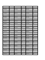
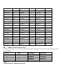
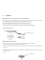
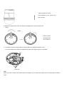
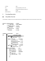
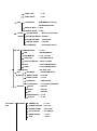
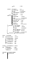
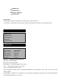
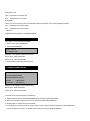
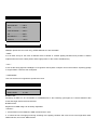
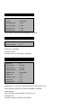
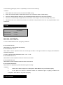
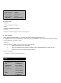
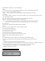
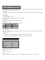
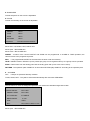
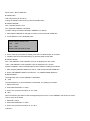
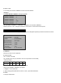
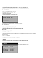
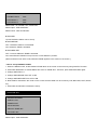
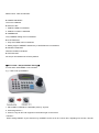
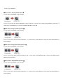
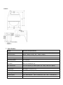
User’s Manual of Speed Domes VPD270, VPD330WD & VPD370WD Series Please read this manual carefully before installation and operation of the product. 1 Rev. 0_August 30, 201 Table of contents 1. Features ----------------------------------------------------------------------------2. Precaution--------------------------------------------------------------------------3. Part Names and Functions ---------------------------------------------■ Body ■ Package ■ Camera cable connection ■ DIP Switch setting ■ Camera ID setting ■ RS-485 Comminication setting Installation -----------------------------------------------------------------------5. Functional description ---------------------------------------------------4. ■ Setup Menu Overview ■ Main Menu 1) PAN/TILT setting 2) Camera setting 3) Autoseq setting 4) Zone setting 5) Alarm setting 6) Initialize setting 7. Product Structure ----------------------------------------------------------8. Specifications ----------------------------------------------------------------- 2 1. Features * Dynamic and precise AF control The camera can trace and pick up the object, moving fast from the scene with powerful 324 times(Optical 27x, Digital 12x), 396 times(Optical 33x, Digital 12x), 444 times(Optical 37x, Digital 12x) zoom by greatly improved Auto Focus control. * Removable Motorized IR Cut Filter(ICR) * Viewable at total darkness The image at daytime displays as True Color with IR Cut filter attached and turns to Clear B/W(color signal removed) mode at night(True Day/Night). With ICR, it comes to IR sensitive and enables the camera to view the scene at total darkness. *Super Wide Dynamic(sWDR) With new powerful DSP system integrated, it makes more 126 times upgraded Backlight compensation than that of existing BLC system * High resolution of 550TVL(Color)/ 680TVL(Night) * Powerful 27x/ 33x/ 37x optical zoom * Extremely upgraded sensitivity of 0.7Lux(Sens-up off)/ 0.002Lux(Sens-up, 256x)/ 0.06Lux(B/W) Clear difference with built –in Super DSP system and ICR mechanism is to surveil Objects clearly at even a starless dark night. In addition the built –in Dynamic Noise Reduction(DNR) removes noises and ghost effect to have the picture quality greatly improved. It also saves the DVR’s recoding capacity up to 70%. * Quick and Easy installation Dome base is separated and easily mounted on the ceiling and the main body is simply hooked on it by hand with no tool. No complicated cable connection is additionally required with the built-in one-stop connection mechanism 3 2. Precaution Safety Precautions * The purpose of this information is to ensure proper use of this product to prevent danger to damage to property. Please be sure to observe all precautions * The precautions are divided into “Warnings” and “Cautions” as distinguished below; Warning : Ignoring these warnings may result in death or serious injury. Caution : Ignoring these cautions may result in injury or damage to property. Warning :instructions alert you to Caution : instructions alert you to the the potential risk of death potential risk of injury or or serious injury damage to property Warnings 1. Be sure to use only the standard adapter which is specified in the specification sheet. Using any other adapters could cause fire, electrical shock, or damage to the product. 2. When connecting the power supply and signal wires, check the external connection terminal before connecting them. Connect the alarm signal wires to the alarm terminals, the AC adaptor to the AC power input receptacle, and the DC adapter to the DC power Input, making sure that the correct polarity is observed. (Connecting the power supply incorrectly may cause fire, electrical shock, or damage to the product.) 3. Do not connect multiple cameras to a single adapter. (Exceeding the capacity may cause abnormal heat generation or fire.) 4. Securely plug the power cord into the power receptacle. (Insecure connection may cause fire.) 5. When installing the camera on a wall or ceiling, fasten it securely and firmly. (A falling camera may cause personal injury) 6. Do not place conductive objects(e.g. screwdrivers, coins, and metal things) or containers filled with water on top of the camera. (Doing so may cause personal injury due to fire, electrical shock or falling objects) 4 7. Do not install the unit in humid, dirty, or sooty locations (Doing so may cause fire or electrical shock.) 8. If any unusual smell or smoke comes from the unit, stop using the product. In such case, immediately disconnect the power source and contact the store of purchase. (Continued use in such a condition may cause fire or electrical shock.) 9. If this product fails to operate normally, contact the store of purchase. Never disassemble or modify this product in any way. 10. When cleaning, do not spray water directly onto parts of the product. (Doing so may cause fire or electrical shock.) Wipe the surface with a dry cloth. Never use detergents or chemical cleaners on the product, as this may result in discoloration of surface or cause damage to the finish. Cautions 1. Do not drop objects on the product or apply strong shock to it. Keep away from a location subject to excessive vibration or magnetic interference. 2. Do not install in a location subject to high temperature(over 122℉), low temperature(below 14℉) or high humidity. (Doing so may cause fire or electrical shock.) 3. Avoid a location which is exposed to direct sunlight or near heat sources such as heater or radiators. (Neglecting to do so may result in a risk of fire.) 4. If you want to relocate the already installed product, be sure to turn off the power and then move or reinstall it. 5. Install in a well-ventilated location. 6. Remove the power plug from the outlet when there is a lightning storm. (Neglecting to do so may cause fire or damage to the product.) 5 3) Part Names and Functions ■ Body Video output Camera Mounting Base Power(24VAC) Alarm Input Relay output RS-485 DATA Safety Wire Decorative Cover(provided) Dome Anchor Ring Dome Cover Rotate the dome anchor ring to the left to remove it. The dome cover is easily damaged And should be handled with care Alarm In/out Cable Lenz Lens 6 ALARM IN 4 RED 5 ALARM IN 3 SHIELD 4 GND YELLOW 3 GND BLUE 2 ALARM IN 2 BLACK ALARM IN 1 WHITE 1 6 Relay Output Cable RS-485 Cable 6 N.C 5 COM2 YELLOW 4 OUT2 BLUE 3 COM1 BLACK 2 OUT1 WHITE 1 N.C + TRX+ - TRX- ■Package 7 8 ■ Camera cable connection ■ DIP SWITCH SETTINGS In a configuration where the camera’s RS485 data port is used for Camera control(pan, tilt, etc.) by the system controller, the camera’s DIP switches must be configured to specify the camera ID and communication parameters. The camera mounting base needs to be removed to access the DIP switches. See step 1 & 2 on page ? for the information about how to remove the camera mounting base. 9 ■ Camera ID setting The factory default settings of these DIP switches are ID 1 (1-ON,0-OFF) SW1~SW8 DIP SW ID DIP SW ID DIP SW ID 10000000 1 10101000 21 10010100 41 01000000 2 01101000 22 01010100 42 11000000 3 11101000 23 11010100 43 00100000 4 00011000 24 00110100 44 10100000 5 10011000 25 10110100 45 01100000 6 01011000 26 01110100 46 11100000 7 11011000 27 11110100 47 00010000 8 00111000 28 00001100 48 10010000 9 10111000 29 10001100 49 01010000 10 01111000 30 01001100 50 11010000 11 11111000 31 11001100 51 00110000 12 00000100 32 00101100 52 10110000 13 10000100 33 10101100 53 01110000 14 01000100 34 01101100 54 11110000 15 11000100 35 11101100 55 00001000 16 00100100 36 00011100 56 10001000 17 10100100 37 10011100 57 01001000 18 01100100 38 01011100 58 11001000 19 11100100 39 11011100 59 00101000 20 00010100 40 00111100 60 DIP SW ID DIP SW ID DIP SW ID 10111100 61 11000110 99 10010001 137 01111100 62 00100110 100 01010001 138 11111100 63 10100110 101 11010001 139 00000010 64 01100110 102 00110001 140 10000010 65 11100110 103 10110001 141 01000010 66 00010110 104 01110001 142 11000010 67 10010110 105 11110001 143 00100010 68 01010110 106 00001001 144 10100010 69 11010110 107 10001001 145 10 01100010 70 00110110 108 01001001 146 11100010 71 10110110 109 11001001 147 00010010 72 01110110 110 00101001 148 10010010 73 11110110 111 10101001 149 01010010 74 00001110 112 01101001 150 11010010 75 10001110 113 11101001 151 00110010 76 01001110 114 00011001 152 10110010 77 11001110 115 10011001 153 01110010 78 00101110 116 01011001 154 11110010 79 10101110 117 11011001 155 00001010 80 01101110 118 00111001 156 10001010 81 11101110 119 10111001 157 01001010 82 00011110 120 01111001 158 11001010 83 10011110 121 11111001 159 00101010 84 01011110 122 00000101 160 10101010 85 11011110 123 10000101 161 01101010 86 00111110 124 01000101 162 11101010 87 10111110 125 11000101 163 00011010 88 01111110 126 00100101 164 10011010 89 11111110 127 10100101 165 01011010 90 00000001 128 01100101 166 11011010 91 10000001 129 11100101 167 00111010 92 01000001 130 00010101 168 10111010 93 11000001 131 10010101 169 01111010 94 00100001 132 01010101 170 11111010 95 10100001 133 11010101 171 00000110 96 01100001 134 00110101 172 10000110 97 11100001 135 10110101 173 01000110 98 00010001 136 01110101 174 DIP SW ID DIP SW ID DIP SW ID 11110101 175 01010011 202 10100111 229 00001101 176 11010011 203 01100111 230 10001101 177 00110011 204 11100111 231 01001101 178 10110011 205 00010111 232 11001101 179 01110011 206 10010111 233 00101101 180 11110011 207 01010111 234 10101101 181 00001011 208 11010111 235 11 01101101 182 10001011 209 00110111 236 11101101 183 01001011 210 10110111 237 00011101 184 11001011 211 01110111 238 10011101 185 00101011 212 11110111 239 01011101 186 10101011 213 00001111 240 11011101 187 01101011 214 10001111 241 00111101 188 11101011 215 01001111 242 10111101 189 00011011 216 11001111 243 01111101 190 10011011 217 00101111 244 11111101 191 01011011 218 10101111 245 00000011 192 11011011 219 01101111 246 10000011 193 00111011 220 11101111 247 01000011 194 10111011 221 00011111 248 11000011 195 01111011 222 10011111 249 00100011 196 11111011 223 01011111 250 10100011 197 00000111 224 11011111 251 01100011 198 10000111 225 00111111 252 11100011 199 01000111 226 10111111 253 00010011 200 11000111 227 01111111 254 10010011 201 00100111 228 11111111 255 ■ RS485 Communication setting Configuring DIP Switch as shown below resets communication parameters from the factory default setting by using SW9 and SW10 SW10 SW9 BUAD RATE PROTOCAL 0 0 9600BPS PELCO-D 0 1 4800BPS PELCO-D 1 0 9600BPS PELCO-P 1 1 4800BPS PELCO-P NOTE Factory Default : 9600bps, PELCO-D 12 4. Installation ■ Preparing the Camera and Decorative Cover for Side Cable Exit The camera and decorative cover should be prepared as shown below when mounting the camera on a ceiling or wall with its cables(power, video output, RS485, alarm in Relay out) exiting from the side. The camera mounting base needs to be removed in order to prepare the camera. See step 1 and 2 below for information about how to remove the camera mounting base. * Prevent the dome cover from being scratched by placing it on a soft cloth while you are working. Preparing the Decorative Cover Cut it off with a razor knife ■ Installing the Camera for Indoor * Select an installation location that is strong enough to withstand the total weight of the camera. Installing the camera at a location that is too week can cause it to fall. * If you are using an optional bracket to install the camera, install the bracket in accordance with the instructions that come with it 1. Remove the fixing screw(M3x6) that secures the camera to the mounting base and put the screw in a place where it will not become lost. Step 1 Fixing screw 13 After loosening the screw, press upwards on the camera and then remove it 2. Rotate the camera base unit in the direction indicated by the arrow and remove it. Step 2 Rotate otate Pull the camera Mounting base Up to remove it 3. To install the camera mounting base to ceiling, attach a template and drill the holes. If you are using the top cable exit configuration, drill the top cable exit part to a template. Mark here Note When you use the camera mount base without a template, you can mark the location of four mounting holes & drill the holes. 14 4. Affix the camera mounting base onto the ceiling. Use screws(M4) at the locations you marked above to secure the mounting base to the ceiling. Screw Screws (M4, available separately) 5. Attach the safety wire for securing the camera to the mounting base. Pull on the safety wire to make sure its ring is securely connected to the mounting base. Safety Wire Ring NOTE The safety wire is designed to allow the camera to hang from it. Do not apply force greater than the weight of the camera to the wire. Safety 6. Install the camera onto the mounting base. Wire ring Aligning with the mounting base, press down on the camera as far as it will go and rotate in the direction indicated by the arrow. 7. Use the fixing screw you removed in step 1 in order to secure the camera to the mounting base. 8. Check the installation * Is the camera leveled and installed securely? 15 * Is the camera free to looseness? * Does the fixed part of the camera remain in place when you try to rotate it? Rotate Back Camera Mounting Base Camera Camera 9. Separate the two parts of the decorative cover(that comes with camera) Press upwards on the decorative cover at the points marked ■(indicated by the arrows in the illustration below) to unlock the two parts from each other. When removing the decorative cover, the direction to press(←) is shown on the side of the decorative cover. Fix securely Unlock Back Back Press Unlock Press Fix securely Press Press Caution Pressing up on the wrong side of the decorative cover can damage it. 10. Put the two parts of the decorative cover on the left and right side of the camera and hook them together. Align the hooks and press one piece indicated by the arrow in the illustration below into the other piece. Hold securely 16 Back Align Press Press Hook Press 11. In case that the cable exits on the ceiling, fix the decorative cover to the ceiling firmly. In case that the cable exits to the side, align the cutout in the decorative cover with the cable and slide the decorative cover up firmly against the ceiling. Top Cable Exit Configuration Side Cable Exit Configuration Align with cutout ■ Installing the Camera for Outdoor Features * Aluminum body and Polycarbonate Dome Cover. * IP66 rated water/dust resistant and remarkable durability. * Built-in Fan, Heater & Temperature sensor. 17 * Quick and easy to install. * Neat design suitable for interior/exterior decoration Precautions * Note that you need to read carefully all contents related to safety and application methods before application. * Be sure to use the Safety Wire Ring. * Fasten the bracket strong enough to support the camera weight(approx. 5.5Kgs) * The locations for installing the housing should be strong enough to fully secure the accessories, and all installations need to be carried out by experienced engineers. * Do not use chemicals for cleaning the enclosure as it may damage the surface. Installation overview Hexagonal Wrench 4-M4x10 Screw Wall mount bracket Wall mount O-Ring Outdoor Main Body Indoor Camera Outdoor Dome Cover Installation 1. Make four holes on the wall using the template provided. 18 2. After removing the mounting fix screw(M3), rotate the camera mounting base clockwise to remove it. 3. Fix the camera mounting base to the inside of the outdoor main body with the four screws(M4x8) 4. Attach the wall mount bracket to the wall and run cables. Be sure to line up it with for holes in the wall. 5. After inserting an O-Ring to the outdoor main body, attach the main body to the wall mount bracket with four screws(M4x10) by wrench. 19 6. After attaching the indoor camera to the camera mounting base, turn and fix it clockwise. And tighten the mounting fix screw with screw driver. 7. Insert the M4 x 10 bolt screws to secure the outdoor dome cover to the outdoor main body. Specification Operating -40°C ~ +50°C Temperature Humidity 0 to 90% RH Power Source AC24V/1A Construction Aluminum & PC Plastic 20 IP rating IP66 Fan AC24V Operating at over 40°C Heater AC24V/18W Operating at below 4°C Weight 5,500g Dimension(mm) Ø260 x 367(H) 5. Functional Description ■ Setup Menu Overview In this chapter, we will look over the overall structure of the Setup Menu and then look at the functions of each menu . PAN/TILT ID DISPLAY → ON/OFF SET CAM NAME → MAIN CAMERA NAME DISPLAY → OFF/ON CAMERA FIRMWARE → ENGLISH DIGITAL FLIP → ON/OFF FREEZE → OFF/ON BACKLIGHT <HLC> SET OFF/<WDR>/<USER> WDR WDR LIMIT → LOW/MID/HIGH WDR LEVEL → 0~100 BLC → LOW/HIGH LEVEL → 1~100 WINDOW TOP WINDOW BOTTOM → 1~100 HLC WINDOW LEFT → 1~100 WINDOW RIGHT → 1~100 HLC LEVEL → LOW/HIGH MASK COLOR → 0~10 MD MD NUM → 1~8 MD DEFINE → OFF/ON MD DISPLAY → OFF/ON SENSITIVITY → LOW/HIGH AREA TOP → 1~26 AREA BOTTOM → 5~39 21 AREA LEFT → 1~44 AREA RIGHT → 5~48 ATW ATW MODE → ATW/MANUAL/<HOLD> OUTDOOR/INDOOR MANUAL RED → 0~200 MANUAL BLUE→ 0~200 FOCUS → MANUAL/AUTO/ZOOMTG FOCUS MODE ZOOM TRK MODE→OFF/ON /ZOOM ZOOM TRK SPD →FAST/SLOW AE DIGITAL ZOOM →OFF/ON ZOOM MAG →2X/4X/6X/8X/10X/12X BRIGHTNESS → 0~100 IRIS → AUTO/MANUAL IRIS MANUAL → F1.6 ~CLOSE SHUTTER → ESC/MAN/A.FLK SHUTTER MAUAL→ X256~1/120000 AGC → OFF/LOW/MID/HIGH SSNR → OFF/LOW/MID/HIGH DSS → X2~X256, OFF DAY & NIGHT D/N MODE → COLOR/BW/AUTO BURST MODE → OFF/ON BURST LEVEL → 0~100 DURATION → FAST/SLOW FILTER DELAY → 5/7/10/20/30/40/60SEC SPECIAL H-REV → OFF/ON V-REV → OFF/ON DIS → OFF/ON SHARPNESS → 0~100 COLOR AUTOSEQ SET PRESET → 0~100 → 1~128 PRESET NO PRESET DEFINE →OFF/<ON> PRESET NAME → OFF/<ON> P/T POSITION → P/T ANGLE BRIGHTNESS → 0~100 ATW → <SET> 22 TOUR BLC → <SET> TOUR NO →1~5 TOUR NO DEF → OFF/<ON> NAME → TOURGROUP1 TOUR NAME DEF → OFF/<ON> → 1~120 DWELL TIME SCAN →1~5 SCAN NO SCAN DEFINE → OFF/ON NAME → SCANGROUP1 SCAN NAME DEFINE→OFF/<ON> PAN START POS →<180> PAN END POS →<350> TILT POS →<45> SCAN SPEED →5˚,10˚,15˚,20˚/S PATTERN PATT NUMBER → 1~2 PATT DEFINE → OFF/ON NAME → PATTERN001 PATT NAME DEF →OFF/<ON> PATT RECORD →OFF/<ON> PATT SPEED AUTO RUN OFF/SEQ/TOUR/SCAN/PATT ZONE AREA SEL → 1~8 SET AREA DEFINE → OFF/ON AREA NEW SET → OFF/ON TOP/BOTTOM-1 → XXX TOP/BOTTOM-2 → XXX LEFT/RIGHT-1 → XXX LEFT/RIGHT-2 → XXX ALARM ALARM DISPLAY → OFF/ON SET ALARM IN → <SET> ALARM OUT → OFF/ON TIME OUT → 1~10SEC INITIALIZE SET → 5˚,10˚,15˚,20˚/S POWER ON RESET PAN/TILT INIT 23 CAMERA INIT AUTOSEQ INIT PRIVACY ZONE INIT FACTORY INIT System INFO This diagram shown above illustrates the overall structure of the setup menu. In this section, a description of the setup menu features will enable users to tailor it to their personal needs. MAIN MENU 1. PAN TILT SET 2. CAMERA SET 3. AUTOSEQ SET 4. ZONE SET 5. INITIALIZE SET 1. PAN TILT SET 1. ID DISPLAY: <ON>/OFF 2. CAM NAME: MAINCAMERA 3. NAME DISPLAY: OFF/<ON> 4. FIRMWARE: ENGLISH 5. DIGITAL FLIP: ON/ OFF 6. FREEZE: OFF/ON Selection : UP, DOWN, LEFT, RIGHT KEY Menu open : IRIS OPEN KEY Menu close : IRIS CLOSE KEY ■ ID DISPLAY – Camera ID appears on the screen. OFF : The ID does not appear on the screen. <ON> : The ID appears on the screen. When changing the location of the ID, press IRIS OPEN KEY in the condition of <ON>. Then, you can move to ID DISPLAY Menu. ■ CAM NAME – Maximum of 10 characters can be input. When changing the camera name, press the IRIS OPEN Key after NAME DISPLAY is set to <ON>. 24 ■ DIGITAL FLIP OFF : It operates TILT below 90°. ON : It operates TILT over 90°. ■ FREEZE When you move to Preset, the screen displays the frozen image of the current displayed preset. OFF : It displays the current image. ON : It displays the frozen image. <Caution> FREEZE works at TOUR in AUTORUN MODE. 1.1. ID DISPLAY ID location can be changed as follows. 1. Select <ON> from ID DISPLAY. 2. Press IRIS OPEN KEY. MOVE: U/D/L/R EXIT: IRISCLOSE Selection : UP, DOWN, LEFT, RIGHT KEY Menu open : IRIS OPEN KEY Menu close : IRIS CLOSE KEY 3. Press IRIS CLOSE KEY when finished. 1.2 CAMERA NAME DISPLAY CAMERA NAME: MAINCAMERA 0123456789ABCDEFGH IJKLMNOPQRSTUVWXYZ DELETE : <IRISOPEN> POSITION : <IRISOPEN> Selection : UP, DOWN, LEFT, RIGHT KEY Menu open : IRIS OPEN KEY Menu close : IRIS CLOSE KEY The method of Camera naming is as follows; 1. Select DELETE and cancel MAINCAMERA by pressing the IRIS OPEN KEY. 2. Move to the desired characters from 0 to Z and press the IRIS OPEN KEY. 3. Repeat step 2 until the name is completed. 4. If you want to change the location of the camera name, select position and press the IRIS OPEN KEY. How to change the location of camera name is the same as changing ID DISPLAY 25 2. CAMERA SET 1. BACKLIGHT----------OFF/<WDR>/USER 2. MOTION DET 3. ATW -----<SET> ----------------<SET> 4. FOCUS/ZOOM ------<SET> 5. AE ----------------------<SET> 6. DAY&NIGHT ---------<SET> 7. SPECIAL --------------<SET> 2.1. BACK LIGHT WDR(for Optical 33x/ 37x zoom only), USER AREA & HLC are selectable. * WDR * It is an ideal set up for the most of different levels of backlit or contrast lighting situations and provides no darker subjects when there are a dark portion and a bright portion on the screen simultaneously. * HLC * It cuts off the strong light like “headlight” to recognize a license plate or subject clear in the entrance of parking garage or at gas station. It doesn’t work at daytime. * USER AREA* User can set area to recognize the specific area clear. 2.1.1. WDR LEVEL SETUP 1. WDR LIMIT: LOW/MID/HIGH 2. WDR LEVEL: 0~100 ■ WDR LIMIT Sensitivity of WDR can be controllable to LOW/MIG/HIGH. If the sensitivity gets higher, the contract between dark areas and bright areas becomes lessened. ■ WDR LEVEL Brightness of WDR image can be wholly adjustable. <Caution> 1. If SHUTTER is set to MANUAL, WDR function doesn’t work. 2. In case that color of image goes wrong according to the lighting condition and noise occurs in the bright area under WDR selection, do not use WDR function. 26 2.1.2. BLC USER SETUP 1. WINDOW OFF/ON 2. LEVEL LOW/HIGH 3. WINDOW TOP 1~100 4. WINDOW BOTTOM 1~100 5. WINDOW LEFT 1~100 6. WINDOW RIGHT 1~100 Above menu is selectable and adjustable by controller. 2.1.3. HLC LEVEL SETUP 1. HLC LEVEL LOW/HIGH 2. MASK COLOR 0~10 ■ HLC LEVEL Sensitivity is adjustable. ■ MASK COLOR Masking color on the high light is adjustable. 2.2. MOTION DETECT 1. MD NUM : 1~8 2. MD DEFINE : OFF/ON 3. MD DISPLAY : OFF/ON 4. AREA DISPLAY OFF/ON 5. SENSITIVITY LOW/HIGHT 6. AREA TOP 1~26 7. ARA BOTTOM 5~30 8. ARA LEFT 1~44 9. AREA RIGHT 5~48 If MD DISPLAY is set to ON, “MOTION” appears on the bottom right. Motion Detection doesn’t work when OSD MENU is activated. ■ MD DEFINE When DEFINE is ON, MD AREA can be set up to 8. ■ SENSITIVITY Sensitivity of Motion Detection is adjustable. 27 If the sensitivity gets higher, there is a possibility to have incorrect workings. <Caution> 1. Motion Detection doesn’t work in SCAN & PATTERN setting. 2. When user uses MD, DWELL TIME should be set over 3 seconds at least in TOUR setting. 3. If there is a shaken lighting directly, do not set the MD because there may be an incorrect working. 4. If there is an instant change for lights which has an effect on the subject, an incorrect working may occurs. 5. This MD function is for neither fire protection nor antitheft so that provider is free from any responsibilities of the malfunction. 2.3. ATW 1. ATW MODE: AUTO/MANUAL/<HOLD>/ OUT DR/IN DR 2. MANUAL RED: 0 ~ 200 3. MANUAL BLUE: 0 ~ 200 Menu Shift : UP, DOWN, LEFT, RIGHT KEY Menu Open : IRIS OPEN KEY Menu Close : IRIS CLOSE KEY It is set to White Balance under any lighting conditions. ■ ATW MODE ATW White Balance is compensated automatically. ■ ATW MODE < HOLD > White Balance will be optimized under the current light condition. If the light condition is changed, White Balance should be readjusted. It works by pressing IRIS OPEN KEY when < HOLD > is off. ■ ATW MODE OUT DR White Balance will be optimized under the outdoor environment. ■ ATW MODE IN DR White Balance will be optimized under the indoor environment. ■ ATW MODE MANUAL White Balance is adjustable by RED and BLUE gains manually. <Caution> 1. When it is too dark or bright on the background, White Balance may not function properly. 2. At the place the camera is directed towards the fluorescent light or lighting conditions are changeable, White Balance may work improperly. 2.4. FOCUS/ZOOM 28 1. FOUCS MODE: 2. ZOOM TRK MODE: MANUAL/AUTO/ZMTRG ON/OFF FAST/SLOW 3. ZOOM TRK SPEED: 4. DIGITAL ZOOM: 5. ZOOM MAG: OFF/ON 2X/4X/6X/8X/10X/12X ■ FOCUS MODE * MANUAL FOCUS is adjustable manually. * AUTO FOCUS is adjustable automatically. * ZMTRG Whenever ZOOM is changed, FOCUS is also readjusted. ■ ZOOM TRK MODE When ZOOM is changed in Wide <-> Tele, user can select if FOCUS will be worked or not. It is applied only to AUTO and ZOOM TRK mode. When user moves ZOOM to a specific area and wants to get faster, ZOOM TRK MODE should be set to Off. <Caution> Under the following conditions, AUTO FOCUS may not work properly. 1. When the lux level is too low or too high 2. When a short distance object and a close distance object appear together in a monitoring area. 3. When there is no contrast between Black and White. ■ ZOOM TRK SPEED The higher value speeds up ZOOM operation. 2.5. AE 1. BRIGHTNESS: 0 ~ 100 2. IRIS: AUTO/MANUAL 3. IRIS MANUAL: F1.6 ~ CLOSE 4. SHUTTER: ESC/MANUAL/A.FLK 5. SHUTTER MANUAL: X256~1/120000 6.AGC: OFF/LOW/MID/HIGH 7. SSNR: OFF/LOW/MID/HIGH 8. DSS: X2~X256, OFF 29 ■ BRIGHTNESS : Brightness on the screen is adjustable. ■ IRIS The brightness on the screen can be adjustable depending on the amount of light through exposure meter. AUTO : The exposure meter is adjusted automatically. MANUAL : User can adjust the exposure meter manually to optimize the brightness on the screen. ■ SHUTTER When capturing a subject, moving fast or under low light condition, user can adjust the shutter speed to faster or slower to get improved images. ESC : Shutter speed is controlled automatically according to the brightness on the screen. MANUAL : Shutter speed is controlled in 1/20000 ~ X128 manually. A.FLK : Use this mode when the screen flickers due to the inconsistent frequency under surrounding lights. In this mode, shutter speed fixed at 1/100 sec. in NTSC system and 1/120 sec. in PAL system. ■ SHUTTER MANUAL Shutter speed is controllable only when SHUTTER is set to MANUAL. ■ AGC Auto Gain Control is to brighten the screen under the low light condition. ■ SSNR ( DIGITAL NOISE REDUCTION ) Noise is lessened under the low light condition. OFF : Noise reduction has no effect. LOW: Noise reduction effect is small but there is little afterimage. MID: Noise reduction effect generally goes proper and afterimage is not strong. HIGH: Noise reduction effect is excellent but afterimage is also strong. ■ DSS By controlling Electronic Shutter, it makes the screen brightened under the low light condition. However, if user sets higher ratio of DSS, afterimage becomes stronger and Auto Focus may not work. <Caution> 1. If possible, do not use A.FLK and WDR mode at the same time. 2. In internal synchronization system, if SHUTTER is set to ESC and the camera faces to sunlight or strong light reflecting areas directly, the screen goes wrong. In this case, change the location of the camera. 3. In case that SHUTTER is set to MANUAL or A.FLK, SENSUP LIMIT doesn’t work. 4. SSNR doesn’t work when AGC is OFF. 2.6. DAY&NIGHT 1. D/N MODE: COLOR/BW/AUTO 2. BURST MODE: OFF/ON 3. BURST LEVEL: 0 ~ 100 30 4.DURATION: FAST/SLOW 5. FILTER DELAY: 5/7/10/15/20/30/40/60SEC B/W mode with removed IR cut filter offers crystallized clear image under low light condition. On the contrary, Color mode with replaced IR cut filter works at daytime. ■ D/N MODE AUTO : Color mode at daytime and B/W mode at nighttime. It is switchable automatically according to the designated lux condition. ■ BURST MODE OFF : BURST signal is removed. ON : BURST signal is output with together B/W Luminance signal. ■ BURST LEVEL BURST LEVEL is adjustable when D/N MODE is COLOR. ■ DURATION Switching over lux condition is selectable in DAY<->NIGHT DAY->NIGHT NIGHT->DAY FAST 2.5LUX 4LUX SLOW 0.8LUX 6LUX ■ FILTER DELAY The duration of Dwell Time of both the lighting conditions can be customized to let the camera divert between daytime and nighttime settings. <Caution> 1. When AGC is OFF, AUTO MODE doesn’t work while COLOR or B/W mode works. 2. If sunlight or halogen lamp is used in B/W mode, Focus may be blurred or dimmed. 2.7. SPECIAL 1. H-REV: OFF/ON 2. V-REV: OFF/ON 3. DIS: OFF/ON 4. SHARPNESS: 0~100 5. COLOR: 0~100 ■ H-REV The screen flips horizontally. ■ V-REV The screen flips vertically. ■ DIS Digital Image Stabilizer compensates the screen from an unstable environment which can move the camera. 31 ■ SHARPNESS Overall sharpness on the screen is adjustable. ■ COLOR Overall color density on the screen is adjustable. 3. AUTOSEQ SET 1. PRESET <SET> 2. TOUR <SET> 3. SCAN <SET> 4. PATTERN <SET> 5. AUTORUN OFF/SEQ/TOUR/SCAN/PATT Menu Shift : UP, DOWN, LEFT, RIGHT KEY Menu Open : IRIS OPEN KEY Menu Close : IRIS CLOSE KEY PRESET : Location of the current PAN/TILT and ZOOM can be programmed. In ALARM or TOUR operation, the camera moves to the programmed preset. SEQ : The programmed PRESET is executed from the lower order successively. TOUR : PRESET works in GROUP. Up to 5 presets per group can be registered and up to 5 groups can be operated. SCAN : PAN movers from the starting point and the ending point and up to 5 scans can be set up. PATTERN : The operation path of PAN/TILT is saved and PATTERN plays PAN/TITL according to the operation path. ■ AUTORUN OFF : It keeps on Operation Standby condition. TOUR, SCAN, PATT : They will be executed automatically after user exits OSD MENU. 3.1. PRESET This function is to move the designated position if user selects the desirable target and location. 1. PRESET NO: 2. PRESET DEFINE: 1~128 OFF/<ON> 3. PRESET NAME: OFF/<ON> 4. P/T POSITION: P/T ANGLE 5. BRIGHTNESS: 0~100 6. ATW: <SET> 7. BLC: OFF/<WDR>/<USER>/<HLC> Menu Shift : UP, DOWN, LEFT, RIGHT KEY Menu Open : IRIS OPEN KEY 32 Menu Close : IRIS CLOSE KEY ■ PRESET NO Total 128 presets can be set up. Change of PRESET NO is done by LEFT and RIGHT KEY. ■ PRESET DEFINE OFF : PRESET doesn’t work ON : Applicable PRESET is workable. Location change of PAN/TILT/ZOOM in PRESET is as follows. 1. After PRESET DEFINE is changed from OFF to ON, press IRIS OPEN KEY 2. Locate PAN/TILT to the desirable place. PREST NAME: PRESET0001 PAN: TILT: XXX XXX ZOOM: T/W EXIT: IRIS CLOSE 3. If user wants to the location of ZOOM, press TELE or WIDE button of controller. 4. Finalize FAN/TILT and ZOOM settings by pressing IRIS CLOSE KEY. ■ PRESET NAME OFF : After PRESET works, PRESET name is not displayed on the screen. <ON> : After PRESET works, PRESET name is displayed on the screen. Default of PRESET name is PRESET0001 and the method of editing is as follows. 1. After changing PRESET NAME from OFF to <ON> and press IRIS OPEN KEY. 2. How to edit PRESET NAME is the same as “1.2 CAMERA NAME DISPLAY”. ■ BRIGHTNESS The brightness of the current PRESET is adjustable. ■ ATW The White Balance of current PRESET is selectable. The setting is as follows. 1. Select ATW menu 2. Press IRIS OPEN KEY in <SET>. 3. How to set up ATW is the same as “2.3. ATW”. ■ BLC When the subject gets darker under the bright background in the current PRESET, this function is useful. How to set up is as follows. 1. Select BLC menu. 2. Press IRIS OPEN KEY in <SET>. 3. How to set up ATW is the same as “2.1. BLC” <Caution> 33 1. When setting PRESET by the shortcut key, PRESET can be set in No.1-No.64 and, regarding over No.65, it should be set up by OSD Menu. 2. Default set up value of BRIGHT, BLC and ATW in PRESET is decided by Factory Default. 3.2. TOUR This function is to repeatedly operate Group Surveillance with programmed presets. 1. TOUR NO: 1~5 2. TOUR NO DEF: OFF/<ON> 3. NAME: TOURGROUP1 OFF/<ON> 4. TOUR NAME DEF: 5. DWELL TIME: 1~120 ■ TOUR NO Maximum 5 groups can be registered. ■ TOUR NO DEF OFF : TOUR Group setting is cancelled. ON : TOUR Group is set up. <Setting example> TOUR NO 1 2 3 4 5 TOUR DEF ON OFF ON OFF ON TOUR will be executed in programmed preset 1, 3 & 5. How to set TOUR GROUP 1 in PRESET is as follows. 1. Register “1” as a TOUR NO. 2. After changingTOUR NO DEF from OFF to <ON>, press IRIS OPEN KEY. 1. PRESET NUMBER OFF/1~128 2. PRESET NUMBER OFF/1~128 3. PRESET NUMBER OFF/1~128 4. PRESET NUMBER OFF/1~128 5. PRESET NUMBER OFF/1~128 3. Input desirable PRESET No. from 1 in serial order. 4. Press IRIS CLOSE KEY to finalize the setting. ■ NAME It changes the name of TOUR GOURP,. How to change the name is as follows. 1. After TOUR NAME DEF changes from OFF to <ON>, press IRIS OPEN KEY. 2. How to change the Tour group name is the same as “1.2 CAMERA NAME DISPLAY”. 34 ■ DWELL TIME It is a waiting time between PRESET execution and next PRESET. <Caution> 1. If TOUR GOURP1 PRESET is set up as follows. 1. PRESET NUMBER 1 2. PRESET NUMBER 2 3. PRESET NUMBER 3 4. PRESET NUMBER OFF 5. PRESET NUMBER 4 After operating as PRESET1 -> PRESET2 -> PRESET3, it is returned to PRESET1. Namely, if there is “OFF” during the operation in serial order, it is returned to the first preset 3.3. SCAN This function is to surveil the designated two points in the designated speed by automatic travel back and forth. 1. SCAN NO 1~5 2. SCAN DEFINE OFF/ON 3. NAME SCANGROUP1 4. SCAN NAME DEF OFF/<ON> 5. PAN START POS <180> 6. PAN END POS <350> 7. TILT POS <45> 8.SCAN SPEED 5°,10°,15°,20°/S ■ SCAN NO Maximum 5 Scans can be registered. ■ SCAN NO DEF OFF : SCAN is cancelled ON : SCAN can be set up (it should be “ON” for the operation in AUTO RUN) <Setting example> SCAN NO 1 2 3 4 5 SCAN DEF ON OFF ON OFF ON SCAN will be executed in programmed preset 1,3 &5. How to set up SCAN1 in PRESET is as follows. 1. Register “1” as s SCAN NO. 2. After changing SCAN DEFINE from OFF to <ON>, press IRIS OPEN KEY. ■ NAME It changes SCAN Name. 35 How to change is as follows. 1. After changing SCAN NAME DEF from OFF to <ON>, press IRIS OPEN KEY. 2. How to change the SCAN name is the same as “1.2 CAMERA NAME DISPLAY”. ■ PAN START POS It sets up the initialized location of SCAN. Controllable angle is 0~ 360° , 0 ~ -360°. How to set up is as follows. 1. Press IRIS OPEN KEY in PAN START POS. PAN START POSITION SET PAN START POSITION: XXX EXIT: IRIS CLOSE PAN Shift : LEFT, RIGHT KEY 2. After shifting to a desirable position, press IRIS OPEN KEY. ■ PAN END POS It sets up the terminated location of SCAN. Controllable angle is 0°~ 360° , 0°~-360°. How to set up PAN END POS is the same as “PAN START POS”. ■ TILT POS It sets up TILT angel in SCAN. Controllable angle is 0~ 90° . How to set up is the same as “PAN START POS” but UP, DOWN KEY should be used for TILT operation. ■ SCAN SPEED It sets up SCAN Speed.. The speed can be set up in 5°/S(Slow) ~ 20°/S(Fast). * Caution * The value of Brightness, WDR, ATW is applied to the setting values on the OSD. 3.4. PATTERN It is to memorize the paths operated with the joystick operation and reenact them. 1. PATT NUMBER 1~2 2. PATT DEFINE OFF/ON 3.NAME PATTERN001 4.PATT NAME DEF OFF/<ON> 5.PATT RECORD OFF/<ON> 6.PATT SPEED 5°,10°,15°,20°/S 36 MENU Shift : UP, DOWN, LEFT, RIGHT KEY MENU Open : IRIS OPEN KEY MENU Close : IRIS CLOSE KEY ■ PATT DEFINE OFF : PATTERN is cancelled ON : PATTERN is set up. If operating it in AUTO RUN, PATT DEFINE should to be ON. ■ NAME It changes PATTERN Name.. How to set up is as follows.. 1. After changing PATTERN NAME DEF from OFF to <ON>, press IRIS OPEN KEY. 2. How to change the name is the same as “1.2 CAMERA NAME DISPLAY”. ■ PATT RECORD OFF : ON PATTERN is not memorized. : PATTERN is momorized. How to set up PATTERN 1. After PATT RECORD changes from OFF to <ON>, press IRIS OPEN KEY. MEMORY FILL: XXX ( Recorded ) START:IRIS OPEN EXIT:IRIS CLOSE PAN/TILT Shift :UP,DOWN,LEFT,RIGHT 2. Move PAN/TILT to the desirable position before starting PATTERN. 3. Press IRIS OPEN KEY to start the process 4. Press IRIS CLOSE to save the process. * Caution * 1. If there is no PAN/TILT movement, no PATTERN is memorized. 2. The value of Brightness, WDR, ATW is applied to the setting values on the OSD. 4. ZONE SET 1.AREA SEL 1~8 2.AREA DEFINE OFF/ON 3.AREA NEW SET OFF/ON 37 4.TOP/BOTTOM-1 XXX 5.TOP/BOTTOM-2 XXX 6.LEFT/RIGHT-1 XXX 7.LEFT/RIGHT-2 XXX MENU Shift : UP, DOWN, LEFT, RIGHT KEY MENU Open : IRIS OPEN KEY MENU Close : IRIS CLOSE KEY ■ AREA SEL Up to 8 PRIVACY AREAs can be set up. ■ AREA DEFINE OFF : PRIVACY ZONE is not activated.. ON : PRIVACY ZONE is activated. ■ AREA NEW SET OFF : Previous PRVIACY ZONE is activated. ON : New PRIVACY ZONE is set up from the current PAN/TILT position. (When it switches from OFF to ON, PRIVACY ZONE appears in the center on the screen.) * How to set up PRIVACY ZONE1* 1. When the MENU is OFF, locate PRIVACY ZONE block in the center on the screen by using PAN/TILT function. 2. Press IRIS OPEN KEY to activate MENU and move to “ZONE SET”. And then, press IRIS OPEN KEY again. 3. Change AREA SEL to 1. 4. Change AREA DEFINE from OFF to ON. 5. Change AREA NEW SET from OFF to ON. 6. New ZONE is activated in the center on the screen and the ZONE can be moved by TOP, BOTTOM, LEFT, RIGHT key. 7. Press IRIS CLOSE KEY to finalize the set up. 5. INITIALIZE SET 1. POWER ON RESET 2. PAN/TILT INIT 3. CAMERA INIT 4. AUTO SEQ INIT 5. PRIVACY ZONE INIT 6. FACTORY INIT MENU Shift : UP, DOWN MENU Open : IRIS OPEN KEY 38 MENU Close : IRIS CLOSE KEY ■ POWER ON RESET The unit is initialized. ■ PAN/TILT INIT 1. PAN/TILT MENU is initialized. 2. PAN/TILT location is initialized. ■ CAMERA INIT Only CAMERA setting menu is initialized.. ■ AUTO SEQ INIT 1. Only AUTO SEQ menu is initialized. 2. Setting angle of PRESET and Memory of PATTERN are not initialized. ■ PRIVACY ZONE INIT PRIVACY ZONE is initialized. ■ FACTORY INIT All set ups are initialized as a factory default. . ※ WTX-1200A – Simple PRESET Setting ※ It works when OSD MENU is not activated. e.g.> How to set up PRESET 1 1. Place PAN/TILT/ZOOM to a desirable place by Joystick. 2. Press Keypad No. 1. 3. Press F1 Key till “SET OK” appears in the bottom right on the screen. <Caution> When setting PRESET by the shortcut key, PRESET can be set in No.1-No.64 and, regarding over No.65, it should 39 be set up by OSD Menu. ※ WTX-1200A – Simple PRESET Shift ※ It works when OSD MENU is not activated. Press F1 key shortly after pressing RRESET number. And then, it moves to the corresponding PRESET. However, it is valid only up to PRESET no. 32 of which PRESET DEFINE is set to ON. ※WTX-1200A - Simple TOUR operation※ It works when OSD MENU is not activated Press F1 key shortly after pressing Keypad No. 71. It works when TOUR DEFINE is ON and TOUR related MENU is set up properly. ※WTX-1200A - Simple PATTERN operation ※ It works when OSD MENU is not activated Press F1 key shortly after pressing Keypad No. 66. It works when PATTERN DEFINE is ON and PATTERN related MENU is set up properly. ※ WTX-1200A - Simple SCAN operatin ※ It works when OSD MENU is not activated Press F1 key shortly after pressing Keypad No. 81. It works when SCAN DEFINE is ON and SCAN related MENU is set up properly. 40 ※ WTX-1200A - Simple Sequency operation ※ It works when OSD MENU is not activated Press F1 key shortly after pressing Keypad No. 70. It works when PRESET is set up. ※ Quick Operation Key Table ※ [PELCO D /P PROTOCOLS] Number 1~64+Preset Function Setting Preset Press Preset button over 2 seconds. 1~64+Preset Executing Preset 66+Preset Executing Scan 70+Preset Executing Sequency 71+Preset Executing Tour 81+Preset Executing Pattern 95+Preset IRIS OPEN (OSD Menu ) 96+Preset IRIS CLOSE 6. Produce Structure(mm) Indoor 41 Outdoor 7. Specification Model 27x/ 33x/ 37x Speed Domes Image sensor 1/4” Super HAD CCD(27x)/ Color Vertical Double Density CCD(33x, 37x) Effective Pixels NTSC : 768(H) x 494(V), PAL : 752(H) x 582(V) H. Resolutions 550TVL(Color)/ 680TVL(B/W) Synchronizing system Internal Scanning system 2:1 Interlaced Video output VBS : 1.0Vp-p Composit, 75 ohms S/N Ratio More than 50dB(AGC off) Min. illumination 0.7Lux/F1.6(Color), 0.0002Lux(Sens-ups, x256), 0.06Lux/F1.6(B/W) OSD On/ Off Digital zoom On/ Off(x2, x4, x8, x10, x12) Day & Night Color/ BW/ AUTO(ICR) Back Light Compensation WDR(for 33x, 37x only)/ BLC/ HLC/ Off Shutter Speed Auto/ Manual(NTSC : 1/60~1/120,000 sec., PAL : 1/50 ~ 1/120,000 sec.) White Balance AWD/ Manual/ ATW(1,800°K ~ 10,500°K) 42 Gain Control Low/ Middle/ High/ Off Sens-up On/ Off(2x ~ 256x) 3D Noise Filter Low/ Middle/ High/ Off Privacy On/ Off(8 Programmable zones) Preset 256 Points Digital Flip On/ Off Focus control Auto/ Manual/ One Push Iris control Auto/ Manual Motion Detection On/ Off(Built-in Alarm output connector) Protocol RS-485(PELCO-D/P) Power Source 24VAC Operating current 20W Max. Lens Auto Focus Digital zoom Zoom ratio Angle of view 37x F3.5~129.5mm(F1.6) 33x F3.5~115.5mm(F1.6) 27x F3.5~94.5mm(F1.6) 37x H : 55.5°(Wide) ~ 1.59°(Tele), V : 42.5°(Wide) ~ 1.19°(Tele) 33x H : 56.3°(Wide) ~ 1.77°(Tele), V : 43.2°(Wide) ~ 1.33°(Tele) 27x H : 55.5°(Wide) ~ 2.24°(Tele), V : 42.5°(Wide) ~ 1.79°(Tele) Aperture ratio 37x : F1.6~F3.9, 33x : F1.6~F3.6, 27x : F1.6~F2.9 Pan/Tilt angle Pan : 360°(400°/sec.), Tilt : -3°~180°(300°/sec.) Operating temperature 14°F~122°F(-10℃ ~ +50℃) Heater option(Outdoor) -40°F~122°F(-40℃ ~ +50℃) Humidity Within 90% RH Measurement(mm) Indoor : 156(Ø) x 236.6(H) Outdoor : 260(Ø) x 367(H) Weight(Approx.g) 3,500(Indoor)/ 5,500(Outdoor) 43