1
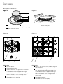
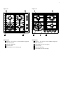
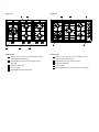
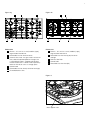
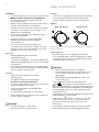
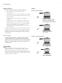
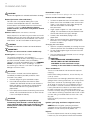
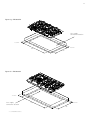
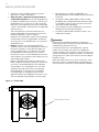
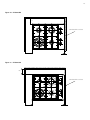
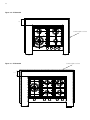
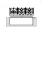
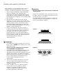
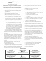
User manual
Gas cooktops EHG313BAEHG643BA
EHG643SAEHG645SA
EHG755SAEHG953SA
EHG953BAEHG955SA
2
WE’RE THINKING OF YOU
Thank you for purchasing an Electrolux appliance.
You’ve chosen a product that brings with it decades
of professional experience and innovation. Ingenious
and stylish, it has been designed with you in mind.
So whenever you use it, you can be safe in the
knowledge that you’ll get great results every time.
Welcome to Electrolux.
BEFORE USING YOUR APPLIANCE
efore you use the cooktop, we recommend that you
B
read through the whole user manual which provides the
description of the cooktop and its functions. To avoid
the risks that are always present when you use a gas
appliance, it is important that the cooktop is installed
correctly and that you read the safety instructions carefully
to avoid misuse and hazards.
For future reference, please store this booklet in a safe
place.
This appliance complies with the requirements of
Australian Standard AS 4551.
CONDITIONS OF USE
This appliance is intended to be used in household and
similar applications such as:
• Staff kitchen areas in shops, offices and
other working environments
• Farm houses
• By clients in hotels, motels and other residential
type environments
• Bed and breakfast type environments.
BEFORE YOU CALL
Please ensure you read the instruction manual fully before
you call for service, or a full service fee could be applicable.
Record model and serial
number here:
Model:
Serial No:
Contents
3
General warnings
4
Part names
8
Using your cooktop
9
Burners
10 Cleaning and care
11 Troubleshooting
12 Technical data
14 Installation instructions
18 Installation procedure
26 Gas connection
27 LP conversion
29 Electrical connection
30 Testing appliance operation
32 Warranty
LEGEND
Warning!
This symbol indicates information concerning your
personal safety.
Caution!
This symbol indicates information on how to avoid
damaging the cooktop.
Important!
This symbol indicates tips and information about use of
the cooktop.
ENVIRONMENT!
This symbol indicates tips and information about
economical and ecological use of the cooktop.
Information on disposal
for users
ENVIRONMENT!
• M
ost of the packaging materials are recyclable. Please
dispose of these materials through your local recycling
depot or by placing them in appropriate collection
containers.
• If you wish to discard this product, please contact your
local authorities and ask for the correct method of
disposal.
3
General Warnings
Please read the user manual carefully and store in a handy
place for later reference. Pass the user manual on to
possible new owners of the cooktop.
Read the following carefully to avoid damage or injury.
Caution!
Read the following carefully to avoid an electric
shock or fire.
It is important to use your cooktop safely. Check these
safety points before using your cooktop.
This symbol indicates never to do this
This symbol indicates always do this
Warning!
• D
o not allow pots to boil dry, as damage to both pan
and cooktop may result.
• Do not operate the cooktop for an extended period of
time without a pot or pan on the burner.
• Do not allow large cookware to overhang the cooktop
onto adjacent benchtop. This will cause scorching to the
benchtop surface.
• Do not allow cooking pots or pans to intrude into the
area which is close to the controls.
• Ensure burner bodies and trivets are properly located
(see Figure 3).
NOTE! You must read these warnings carefully
before installing or using the cooktop. If you need
assistance, contact your Customer Care Department.
The manufacturer will not accept liability, should these
instructions or any other safety instructions incorporated
in this book be ignored.
This appliance is not intended for use by persons
(including children) with reduced physical, sensory
or mental capabilities, or lack of experience and
knowledge, unless they have been given supervision or
instruction concerning use of the appliance by a person
responsible for their safety.
Children should be supervised to ensure they do not
play with this appliance.
During use, this appliance becomes hot. Care should
be taken to avoid touching hot surfaces. To avoid
burns, young children should be kept away.
This appliance must not be used as a space heater.
Keep vents clear of obstructions.
In order to avoid a fire, this appliance must be
kept clean.
Do not spray aerosols in the vicinity of this appliance
while it is in operation.
Do not store flammable materials on or under this
appliance, e.g. aerosols.
Do not remove the trivet and enclose the burner with
a wok stand as this will concentrate and deflect heat
onto the burner.
Do not use large pots or heavy weights which can
bend the trivet or deflect flame onto the burner.
Do not place anything, e.g. asbestos mat between
pan and trivet as serious damage to the cooktop
may occur.
For maximum stability, ensure pots and pans are
centrally located on the trivets.
Handles should be turned away from the front of the
bench to avoid accidents.
Do not modify this appliance.
Only models fitted with flame safeguard can be used
in marine craft, caravans or mobile homes.
4
part names
Description of the burner
Figure 1a
Figure 1b
1
2
3
4
5
1
Burner
4
Injector
2
Skirt
5
Ignition spark plug
3
Flame safeguard sensor
Figure 2b
Figure 2a
1
5
Burner flame ports
1
2
4
3
EHG313BA
1 Dual wok burner
2 Enamelled burner skirt
3 Ceramic Glass hob – the glass hob is resistant to
heat, cold and rapid temperature changes, but
is vulnerable to impact. A pepper mill falling on
the hob could crack it. Never stand or put heavy
loads on the hob, or use as a storage space
4 Control knob
5 Removable cast iron trivet (left)
5
4
2
3
EHG643BA
1 Burners – this unit has a small, medium, large and
dual wok burner
2 Ceramic Glass hob – the glass hob is resistant to
heat, cold and rapid temperature changes, but
is vulnerable to impact. A pepper mill falling on
the hob could crack it. Never stand or put heavy
loads on the hob, or use as a storage space
3 Control knob
4 Enamelled burner skirts
5 Removable cast iron trivet (2 per)
5
Figure 2c
Figure 2d
1
4
2
3
EHG643SA
1 Burners – this unit has a small, medium, large and
dual wok burner
2 Stainless Steel hob
3 Control knob
4 Removable cast iron trivet (2 per)
1
5
2
4
3
EHG645SA
1 Burners – this unit has a small, medium, large and
dual wok burner
2 Removable cast iron trivet (right)
3 Control knob
4 Stainless Steel hob
5 Removable cast iron trivet (left)
6
Figure 2e
Figure 2f
1
1
2
5
5
4
2
3
4
3
EHG755SA
1 Burners – this unit has a small, medium (2 per),
large and dual wok burner
2 Removable cast iron trivet (2 per) for centre
and right
3 Stainless Steel hob
4 Control knob
5 Removable cast iron trivet (left)
EHG953SA
1 Burners – this unit has a small, medium (2 per),
large and dual wok burner
2 Removable cast iron trivet for centre
3 Stainless Steel hob
4 Control knob
5 Removable cast iron trivet (2 off for left and right)
7
Figure 2g
Figure 2h
1
6
5
2
3
4
EHG953BA
1 Burners – this unit has a small, medium (2 per),
large and dual wok burner
2 Removable cast iron trivet for centre
3 Ceramic Glass hob – the glass hob is resistant to
heat, cold and rapid temperature changes, but
is vulnerable to impact. A pepper mill falling on
the hob could crack it. Never stand or put heavy
loads on the hob, or use as a storage space
4 Control knob
5 Removable cast iron trivet (2 off for left and right)
6 Enamelled burner skirts
1
5
4
2
3
EHG955SA
1 Burners – this unit has a small, medium (2 per),
large and dual wok burner
2 Removable cast iron trivet (2 per) for centre
and right
3 Stainless Steel hob
4 Control knob
5 Removable cast iron trivet (left)
Figure 3
Wok support trivet
8
Using your cooktop
Installation
• A
n authorised person must install this appliance and
MUST provide a Certificate of Compliance.
This certificate should be retained along with
purchase information.
• Before using the appliance, ensure that all packing
materials are removed from the appliance.
• In order to avoid any potential hazard, the installation
instructions in this booklet, and any labels on the
appliance must be followed.
• Ensure that all specified vents, openings and air
spaces are not blocked.
• Where the appliance is built into a benchtop,
the benchtop material must be capable of
withstanding 85°C.
• Ensure that the duplicate rating label (in the
instruction pack) is attached to a readily accessible
adjacent surface, so that the cooktop can be easily
identified in the case of a service call.
Servicing
• S
ervicing MUST only be carried out by
authorised personnel.
• To maintain safe operation, it is recommended that the
product be inspected every five years by an authorised
service person.
• If the supply cord is damaged, it must be replaced by
the manufacturer, its service agent or similarly qualified
persons in order to avoid a hazard.
Cleaning
• A
lways ensure the appliance is turned off
before cleaning.
• This appliance contains aluminium fittings.
Do not use caustic based cleaners.
• Do not use steam cleaners as this may cause moisture
build up on electrical components.
• Always clean the appliance immediately after
any food spillage.
• Do not place any components in a dishwasher.
• Refer to page 10 for care and cleaning instructions for
stainless/ ceramic hob panel.
Caution!
• Do not place burners in a dishwasher.
• Do not place trivets in the dishwasher.
Controls
Each burner is controlled by a control knob. The markings
on the control panel indicate which burner the knob
controls, and the setting for that burner (see Figure 4).
Figure 4
Dual wok burner
Other burners
NOTE! Gas controls turn anticlockwise from ‘OFF’ and have
limited movement.
Lighting burners
Electronic ignition: These cooktops are fitted with
mains powered ignition. When the appliance has been
connected and the power is on, depressing any knob
will release sparks to all burners.
Caution!
• Keep hands clear of burners when lighting.
• If burner does not light within 5 seconds, turn knob
to ‘OFF’ position, allow gas to disperse, then try
lighting again.
• Burners MUST be operated between ‘HIGH’ and
‘LOW’ settings only.
To light a burner, the knob must be turned to the
or
‘HIGH’ position, then pushed down as far as
possible for approximately 5 seconds. If the flame goes out
when the knob is released simply depress the knob again,
this time holding it down with slightly more force for the
same length of time.
The height of the flame can be varied by turning the control
knob toward the ‘LOW’ position.
Note! When the wok burner is turned to low only the
small inner ring stays lit. This is a normal function of
the dual wok burner to provide a very low power
flame option.
In the absence of electrical power, carry out the ignition
directly to the burner with a hand held ignition source.
9
Burners
Choice of burner
For your convenience there is a choice of burners:
• A small burner for special low heat and
slow cooking.
• A medium burner for normal cooking and simmering
(one on the four burner models and two on the five
burner models).
• A large burner for fast heating and large pots
and pans.
• A wok burner for very fast heating using a wok or
large pot or pan. This wok burner is also a “dual”
burner and therefore results in a small low powered
flame when the burner is turned down. This is
achieved by only supplying gas to the inner ring of
the wok burner.
To conserve gas place the pan centrally over the burner
and adjust the flame so that it does not extend past the
edge of the pan (Figure 5). Do not boil food too rapidly.
A vigorous boil will not cook food any faster, and will
waste energy.
Pots and pans
All common pots and pans; aluminium, stainless steel,
cast iron, ceramic, etc., may be used on your new gas
cooktop. Ensure that the pots or pans are steady and have
flat bases to avoid dangerous spill-over of hot liquids and
wasted energy.
Caution!
Never use asbestos mats, wire mats or grids, or
aluminium foil as it can lead to overheating, cracked
enamel or broken glass. The warranty will be void if
these items are used and cause a failure. Woks should
only be used on the wok burner and wok support trivet
(refer to Figure 3 on page 7).
Figure 5
Choice of flame height
7
Incorrect – flame too high
and will cause gas waste
and possible handle damage.
3
Correct flame height.
Gas saved.
Choice of cooking utensils
3
For a large burner,
use a large utensil.
3
For a small burner,
use a small utensil.
10
Cleaning and care
Caution!
Ensure the appliance is off and cool before cleaning.
Enamel (on burner skirts and trivets)
Persistent stains may require rubbing with a nylon
scourer or creamed powder cleansers. Household
enamel cleaners are available, follow the manufacturer’s
instructions in their use. Harsh abrasive cleaners,
powder cleaners, steel wool or wax polishes should
not be used.
Stainless steel (Models with Stainless Steel hob)
Simply wipe with a soft cloth using warm water and a mild
detergent and rinse with clean water. Where stainless steel
has become extremely dirty or discoloured, use a stainless
steel cleaner – but be sure to follow the brushing lines.
Caution!
Do not use abrasive cleaners or harsh solvents.
Important!
Scrapers are to be used on ceramic models only
Ceramic glass (on models with glass hob)
The specially treated glass in the product is
manufactured using the latest technology to the highest
possible standards for both safety and reliability.
However, it must be remembered that as it is CERAMIC
GLASS, it may break. Treat it accordingly. To clean
the ceramic glass hob use a soft cloth or sponge with
detergent and warm water.
Caution!
If the surface is cracked, switch off the appliance
immediately to avoid the possibility of electric shock.
If the hob is very soiled:
1.Remove soilage using the razor blade scraper.
2.Use a hob cleaner product after there has been
sufficient time allowed for the hob to cool. Shake the
bottle and apply a small quantity of cleaner directly
onto the hob. Rub clean using a damp cloth or
paper towels.
3.Use a damp cloth to remove all remaining traces of the
cleaner, which could otherwise burn on when the hob
is next used. Wipe the hob dry.
Caution!
Use the scraper supplied to remove spillages
immediately, while the hob is still hot! Especially
sugar and foods with a high sugar content (eg. jam),
melted plastics and foil, all of which can damage
the hob if left.
Razor blade scraper
Use the scraper to remove spillages from the ceramic hob.
How to use the razor blade scraper:
1.Pull back the protective cover until the blade is visible.
2.Make sure that the razor blade is clean and not worn.
There is a risk, otherwise, that it might damage the
hob. New razor blades can be bought
from pharmacies.
3.Angle scraper at approx. 45° and scrape away the
spillage. The razor blade can be pressed down hard
onto the hob without causing any damage.
4.Carefully clean the blade by wiping it with a
paper towel.
5. When you have finished, press the protective cover
forwards as far as it will go. Keep the scraper out of
the reach of children.
Changing the razor blade:
1.Open the scraper by completely unscrewing the screw
and then place the new razor blade at the front edge.
2.Put the scraper together again and screw the screw
back into place.
3.Press the protective cover forwards as far as it will go
to cover the razor blade.
Caution!
THE RAZOR BLADE SCRAPER SHOULD
BE KEPT WELL OUT OF THE REACH OF
CHILDREN. Use the razor blade scraper
carefully, as the razor blade is extremely sharp.
Trivets and burners
These can all be lifted off and removed for separate
cleaning.
NOTE! When refitting the burners, ensure that they are
correctly seated.
Ensure burners are thoroughly dried after cleaning or
spillage. When cleaning the burners, ensure that all the
flame ports are free of any blockage (refer to Figure
1b on page 4). If necessary, use a toothpick or brush
to clear ports. The outer surface of the burner caps
have a polished finish and extra care needs to be taken
to avoid scratching this surface during cleaning. In
instances of heavy soiling, it may be necessary to apply
a non-abrasive cleaning compound and rub with a cloth
until the soiling is removed and then finish with a soft,
dry cloth.
NOTE! DO NOT place trivets or burners in the
dishwasher.
Ignition spark plug and flame safeguard sensor
GENTLY clean the ignition spark plug and flame
safeguard sensor with a damp cloth to avoid lighting
difficulties. Ensure that they are dry before use.
Injector
Ensure the injector remains free of any foreign material.
If necessary, use a thin piece of wire to clear the orifice.
11
Troubleshooting
If you have a problem with the cooktop, check the table
below. You may be able to solve the problem and this
will save you from paying for a service call. You will have
to pay for a service call even in the warranty period if the
problem is one listed below.
Table 1
problem
possible cause
solution
Burner will not light
even though the
sparker is working
• K
nob not held down long enough in ‘HIGH’
position for flame safeguard.
• R
epeat lighting procedure and hold knob
down for 5 seconds in ‘HIGH’ position.
(Refer page 8).
• Gas supply valve turned off.
• Turn on gas supply to appliance.
• Wrong knob turned.
• E
nsure the knob you are turning corresponds
to the burner you want to light.
• Port blockage in ignition area.
• E
nsure that ports in ignition area are clean
and dry.
• Ignition spark plugs wet or dirty.
• Dry or clean ignition spark plugs.
No spark is
obtained when
control knob is
activated
• E
lectricity supply is disconnected or switched
off.
• Switch on electricity or check fuses.
• Ignition spark plugs wet or dirty.
• Dry or clean ignition spark plugs.
Flames uneven or
tending to lift
• Flame ports blocked or wet.
• Clean or dry flame ports.
• Burner cap incorrectly fitted.
• Ensure this component is fitted correctly.
Flames not staying
on when knob is
released
• K
nob not held down long enough in ‘HIGH’
position for flame safeguard
to engage.
• R
epeat lighting procedure and hold knob
down for 5 seconds in ‘HIGH’ position.
(Refer page 8).
• K
nob not set between ‘HIGH’
and ‘LOW’
• K
nob MUST be set between
these positions.
• D
irt or spillage on flame
safeguard sensor.
• Clean flame safeguard sensor tip.
Low heat,
slow cooking
• Incorrect cooking pot or pan being used.
• Refer to Figure 5 (page 9).
Benchtop or knobs
overheating
• Incorrect cooking pot or pan used.
• Refer to Figure 5 (page 9).
• Pot or pan not located on burner properly.
• E
nsure pot or pan is centrally located on
burner.
Cooktop stainless
steel discloloured
• Pot or pan being used is too large.
• E
nsure pot sizes used are as per user
manual requirements. Clean with STEEL
POWER (available through spare parts).
Outer ring of wok
burner goes out
when set to low
• This is not a failure. This is a function of the
dual wok burner to give a very low power
flame option.
• No remedy - burner is functioning
as intended.
12
Technical data
We reserve the right to alter these specifications.
This appliance conforms to AS 4551.
Table 2
features
EHG313BA
EHG643BA
EHG643SA
EHG645SA
1
4
4
4
Wok
Yes, dual
Yes, dual
Yes, dual
Yes, dual
Ignition
220-240V
220-240V
220-240V
220-240V
Cast
Cast
Cast
Cast
Hob material
Ceramic glass
Ceramic glass
Stainless steel
Stainless steel
Features
Ignition through
knob
Ignition through
knob
Ignition through
knob
Ignition through
knob
Yes
Yes
Yes
Yes
Black
Black
Stainless steel
Stainless steel
NG, (LP conversion
kit supplied)
NG, (LP conversion
kit supplied)
NG, (LP conversion
kit supplied)
NG, (LP conversion
kit supplied)
Width
320
610
600
595
Depth
520
520
520
530
Height
56
56
45
44
Width
303
570
570
560
Depth
485
490
490
490
Small burner
NA
5.1
5.1
5.1
Medium burner
NA
9.0
9.0
9.0
Large burner
NA
12.1
12.1
12.1
Wok burner
17.0
17.0
17.0
17.0
Total MJ/h
17.0
43.2
43.2
43.2
Cooking zones
Trivet
Flame safeguard
Colours
Gas types
cooktop dimensions mm
cut out dimensions mm
energy rating (NG) – MJ/h
13
Table 2 continued
features
EHG755SA
EHG955SA
EHG953BA
EHG953SA
5
5
5
5
Wok
Yes, dual
Yes, dual
Yes, dual
Yes, dual
Ignition
220-240V
220-240V
220-240V
220-240V
Cast
Cast
Cast
Cast
Hob material
Stainless steel
Stainless steel
Ceramic glass
Stainless steel
Features
Ignition through
knob
Ignition through
knob
Ignition through
knob
Ignition through
knob
Yes
Yes
Yes
Yes
Stainless steel
Stainless steel
Black
Stainless steel
NG, (LP conversion
kit supplied)
NG, (LP conversion
kit supplied)
NG, (LP conversion
kit supplied)
NG, (LP conversion
kit supplied)
Width
745
895
861
860
Depth
530
530
520
520
Height
44
44
55
47
Width
730
880
830
830
Depth
490
490
470
470
5.1
5.1
5.1
5.1
2 x 9.0
2 x 9.0
2 x 9.0
2 x 9.0
Large burner
12.1
12.1
12.1
12.1
Wok burner
17.0
17.0
17.0
17.0
Total MJ/h
52.2
52.2
52.2
52.2
Cooking zones
Trivet
Flame safeguard
Colours
Gas types
cooktop dimensions mm
cut out dimensions mm
energy rating (NG) – MJ/h
Small burner
Medium burner
14
Installation instructions
This appliance must be installed by an authorised person
and in compliance with:
1.AS/NZS 5601.1 Gas Installations Part 1: General
Installations, and AS/NZS 5601.2 Gas Installations
Part 2: LP Gas installations in caravans and boats for
non-propulsive purposes, or the relevant installation
code for gas appliances in your country.
2. The local gas fitting regulations, municipal building
codes, electrical wiring regulations and any other
relevant statutory regulations.
3.The particular instructions as given below.
4.A certificate of compliance MUST be given
to the customer after the application is
successfully installed.
Caution!
Cooktops are supplied set up for natural gas (NG).
To use on LPG, the injectors must be changed using
the conversion kit supplied. Refer LP conversion on
page 24-25.
Figure 6a – EHG313BA
Gas supply
connection location
63 min*
116 min*
490
300
Figure 6b – EHG643BA
Gas supply
connection location
161 min*
130 min*
570
490
* to combustible surface
15
Figure 6c – EHG643SA
Gas supply
connection location
136 min*
120 min*
570
490
Figure 6d – EHG645SA
Gas supply
connection location
146 min*
146 min*
560
490
* to combustible surface
16
Figure 6e – EHG755SA
149 min*
135 min*
Gas supply
connection location
730
490
Figure 6f – EHG953SA
Gas supply
connection location
136 min*
116 min*
830
470
* to combustible surface
17
Figure 6g – EHG953BA
Gas supply
connection location
156 min*
126 min*
830
470
Figure 6h – EHG955SA
124 min*
Gas supply
connection location
146 min*
880
490
* to combustible surface
18
Installation procedure
1.
The bench cutout should be made as per cutout
dimensions in Table 2 and Figure 6.
2.
Adjacent walls, cupboards and protection for
combustible materials: Ensure that the appliance is
installed in accordance with clauses 6.2.5 and 6.10.1.1
of AS/NZS 5601.1, or clauses 6.9.1 and 6.9.5 of AS/
NZS 5601.2 with regard to clearances to combustible
surfaces and materials, and clearances to rangehoods
and exhaust fans.
To ensure clearances of 200mm from burners to
vertical combustible surfaces observe the minimum
distance requirements shown in Figure 7.
Clearances to combustible surfaces may be reduced
if combustible surfaces are protected in accordance
with clause 6.10.1.2 of AS/NZS 5601.1, or clause 6.9.2
of AS/NZS 5601.2.
3.
Barrier: A barrier must be installed to prevent
accidental contact with the cooktop base, where the
base of the cooktop is accessible from below (i.e.
Inside a cupboard, etc.). An impression has been
incorporated into the base to ensure a minimum
clearance of 15mm is maintained between the base
and the barrier. This barrier may be made of any noncombustible, rigid material.
Note: An alternative to the above is to purchase a
barrier shield from Electrolux spare parts (P/No. ACC
072) which can be fitted directly to the underside
of the product. This shield protects the user from
accidently touching certain areas of the product.
Barrier protection is not necessary if the product
is installed above an underbench oven or similar
appliance and/or if the cupboard construction is such
that the underside of the cooktop is not accessible.
4.For Ceramic Glass models a FOAM SEAL has
been provided and is to be applied along the perimeter
of the hob.
5.For Stainless Steel models MASTIC TAPE has been
provided and is to be placed around the bench cutout
as specified in Figure 8. Take care to ensure that the
seals meet without overlapping.
6.Fit the pull down clamps supplied to ensure that the
cooktop cannot move after installation.
7.On Stainless Steel models remove any excess seal
visible after installation.
WARNING!
Failure to fix the cooktop to the bench could result in
loosening of the gas connection through movement of the
cooktop and a gas leak may result.
Four clamps and screws are supplied with 4-burner
models and six clamps and screws are supplied with
5-burner models. Fit the clamps as shown in Figure 8. No
clamps are needed for model EHG313BA as it is fitted with
spring clips on the sides which locate on the inner edge of
the bench cutout.
When benchtops are less than 33mm in thickness, it may
be necessary to fit a spacer between the benchtop and
each clamp to ensure clamps can be tightened sufficiently.
Figure 7a – EHG313BA
48
Combustible surface
106
106
19
Figure 7b – EHG643BA
116
Combustible surface
142
15
Figure 7c – EHG643SA
106
Combustible surface
121
13
20
Figure 7d – EHG645SA
115
Combustible surface
129
113
Combustible surface
Figure 7e – EHG755SA
115
142
126
21
Figure 7f – EHG953SA
Combustible surface
90
121
no minimum distance
requirement
Combustible surface
Figure 7g – EHG953BA
101
141
no minimum distance
requirement
22
Combustible surface
Figure 7h – EHG955SA
115
117
101
Figure 8 – Clamp fitment
Hob
Seal
Benchtop
Burner Box
Clamp
Screw
23
Figure 8a - Mastic seal position for model EHG643SA
10mm
10mm
10mm
10mm
Figure 8b - Mastic seal position for model EHG645SA
25mm
12mm
12mm
24
Figure 8c - Mastic seal position for model EHG755SA
25mm
Figure 8d - Mastic seal position for model EHG953SA
20mm
20mm
10mm
10mm
25
Figure 8e - Mastic seal position for model EHG955SA
25mm
26
Operation on N.G./S.N.G.
Gas connection
This appliance is supplied for use with Natural Gas.
However, it can be converted for use with LPG.
Refer to LP conversion on page 24 & 25.
Supply pipe sizing
The total hourly gas consumption for the appliance is
shown on the data label. The required supply pressure
(i.e. at inlet to appliance regulator) for each gas type is
shown on the data label, and given in Table 3 (page 24).
Use this information in conjunction with the length of run,
number of elbows, tees and bends, the available service
pressure and the supply requirements of other installed
appliances to determine a suitable pipe size.
For assistance in this matter refer to the appropriate
section of AS/NZS 5601.1 or AS/NZS 5601.2.
An AGA certified class B or D flexible connection may
be used to connect the cooktop in accordance with
AS/NZS 5601.1, in particular section 5.9 and clause
6.10.1.8, or AS/NZS 5601.2, in particular section 2.11.
Where a hose assembly is used and the cooktop is in the
installed position, the hose assembly shall be suitable for
connection to a fixed consumer piping outlet located at
a point 800 – 850mm above the floor and in the region
outside the width of the appliance to a distance of 250mm.
The point of connection to consumer piping must be
accessible with appliance installed.
Elbow positioning
It is possible to reposition the elbow if required by
loosening the locking nut and elbow by using two
spanners. Re-tighten the entire assembly after the elbow
has been repositioned. When fitting elbow to appliance,
ensure that the sealing washer is fitted.
Note to Installer: Assembly of elbow to manifold
at rear of unit requires two spanners to secure locking
nut and ensure leak free connection. For this reason the
elbow is best secured onto cooktop manifold before
installing unit into benchtop.
Regulator
An appliance regulator is provided. The regulator must be
positioned so that the pressure test nipple is accessible
when the appliance is installed.
Connect the gas supply to the ½” B.S.P. internal thread
inlet of the regulator. Refer to ‘bench cutout’ (Figure 6) for
connection point position.
Regulators are supplied pre-adjusted and configured by
the component maker for use with Natural Gas.
The appliance installer is not required to make an
adjustment to obtain the correct outlet pressure setting.
An arrow on the base of the regulator indicates the
direction of gas flow when the inlet and outlet of the
regulator is orientated correctly. When the regulator has
been fitted check for leaks from the connections with
soapy water.
27
Operation on N.G./S.N.G.
Checking the gas supply
Assembly of Regulator
The assembly of the regulator to the cooktop manifold
is achieved via the elbow union and sealing washer
supplied, refer to figure 9.
The ½” parallel thread connects to the manifold, and the
sealing washer is placed between the manifold end and
the flat face on the elbow.
The ½” tapered thread connects to the outlet of
the regulator, and is sealed on the thread using
approved thread sealing tape or approved thread
sealing compound.
The inlet of the regulator is a ½” parallel thread and
is connected to consumer piping or hose assembly.
Regulators are supplied pre-adjusted and configured
by the component maker for use with Natural Gas.
The appliance installer is not required to make an
adjustment to obtain the correct outlet pressure setting.
An arrow on the base of the regulator indicates the
direction of gas flow when the inlet and outlet of the
regulator is orientated correctly. When the regulator has
been fitted check for leaks from the connections with
soapy water.
Figure 9
Manifold
endform
Female nut
Sealing
washer
½” Parallel
thread
½” Tapered thread
Seal using approved
sealing tape or
approved thread
sealing compound
1. Check the manometer zero point is correct.
2.Connect the manometer to the cooktop pressure
point. This is located on the regulator.
3.Turn on the gas supply and electricity and try to
ignite the gas.
NOTE! It will take additional time to light the gas for the
first time as air needs to be purged from the pipes.
4. With the appliance operating check the outlet pressure
• when all burners of the appliance are operating
at maximum,
• when the smallest burner of the appliance is
operating at minimum.
Under these conditions the outlet pressure should not
vary from the nominal outlet pressure of 1.00kPa by
more than ±0.20kPa.
If the regulator appears to not be performing satisfactorily,
then check the following points:
1.If the outlet pressure is consistently too low then the
inlet pressure may be too low and adjustment of an
upstream regulator may be needed, or an upstream
regulator or valve with insufficient flow capacity may
be present in the gas supply line. If this is suspected
then it may be necessary to repeat the checks whilst
measuring both the inlet and outlet pressure to
determine if the inlet pressure is in the range
1.13 – 5kPa.
2. Check that the regulator has been fitted to the gas
supply line in the correct orientation, the arrow on the
base of the body indicates the direction of gas flow.
Once these checks have been completed, if the
regulator still fails to perform in a satisfactory manner it
should be replaced.
Flat face
Outlet
LP Conversion – Important
This appliance is fitted with Natural Gas
burner injectors.
Please follow the procedure below if a conversion to suit
LP gas is required.
The conversion kit contains appropriate LPG injectors
and 1 LPG sticker.
1.Remove the hotplate burners to access the hotplate
injectors. Replace the factory fitted NG injectors with
the appropriate injectors, as supplied (see Table 3).
Regulator
Inlet
Table 3
burner type
natural gas (nominal test point pressure: 1.00kPa)
LPG (nominal test point pressure: 2.60kPa)
injector size (mm)
gas consumption (MJ/h)
injector size (mm)
gas consumption (MJ/h)
Small burner
1.00
5.1
0.55
4.2
Medium burner
1.35
9.0
0.70
6.5
Large burner
1.60
12.1
0.90
10.7
Wok burner
0.85 + 2 x 1.25
17.0
0.46 + 2 x 0.73
17.0
28
2.Unscrew the hex nut from the regulator. The hex
nut, brass washer and nylon insert will disengage as
an assembly.
3.Unclip the nylon insert and nut assembly by rotating
the insert ¼ turn, and pulling it free.
4.Turn over the insert and clip back into position.
5. Refit the hex nut assembly to the regulator ensuring
that it is fully screwed down. The regulator is now
set for connection to LP.
6.Turn on the gas supply and at each new connection
check for leaks using soapy water: each hotplate
valve should be turned on, one at a time, and the
injector hole blanked off for several seconds.
7. The operation of the regulator can be confirmed by
connecting a manometer to the pressure test point
located on the side of the regulator body adjacent to
the outlet.
With the appliance operating check the
outlet pressure:
• when all burners of the appliance are operating
at maximum,
• when the smallest burner of the appliance is
operating at minimum.
Under these conditions the outlet pressure should not vary
from the nominal outlet pressure of 2.60kPa by more the
+/-0.52kPa.
8.If the regulator appears to not be performing
satisfactorily then check the following points:
• If the outlet pressure is consistently too low then
the inlet pressure may be too low and adjustment
of an upstream regulator may be needed, or an
upstream regulator or valve with insufficient flow
capacity may be present in the gas supply line.
If this is suspected then it may be necessary to
repeat the checks whilst measuring both the
inlet and outlet pressure to determine if the inlet
pressure is in the range 2.75 – 7.00kPa.
• Check that the insert has been fitted correctly as
per diagram figure 10. Check that the hex nut is
fully screwed down.
• Check that the regulator has been fitted to the
gas supply line in the correct orientation, the arrow
on the base of the body indicates the direction of
gas flow.
Once these checks have been completed, if the
regulator still fails to perform in a satisfactory manner it
should be replaced.
9. One by one, turn the knobs to minimum and screw
in the bypass screw (accessible when the knob is
removed) until a small stable flame results. Turn the
knob to maximum and then back to minimum to
ensure that the correct minimum flame is maintained.
10. Attach the LPG sticker to the cooker, near the gas
supply inlet. Cover the Natural Gas label that is
factory fitted.
Use of hose assembly
Ensure that the hose assembly is restrained from
accidental contact with the flue outlet of an underbench
oven or any other hot surface of an adjacent appliance.
Hex nut
assembly, fully
screwed down
Figure 10
Hex nut assembly,
removed
from regulator
and insert
disassembled
Insert
oriented for
natural gas
operation
Insert
oriented
for LPG
operation
29
Electrical connection (220-240 Volts)
The appliance is supplied with a standard 7.5 Amp
service cord terminated by a 3-pin plug for connection
to a standard household socket. The electrical supply is
required to power the electronic ignition system.
NOTE! It will be necessary for servicing purposes to
disconnect the electrical power supply. The power
point should therefore be accessible after the appliance
is installed, as specified in the local wiring regulations.
Diagram 1 is a schematic of the wiring in the appliance.
WEIGHT of the unit is printed on the appliance
packaging label.
Diagram 1a – All models except EHG313BA
DANGER
220-240 VOLTS AC
DISCONNECT FROM SUPPLY
BEFORE REMOVING PANEL
boDY
E
N
L
220-240V
ignition
box
TO BURNER SPARK PLUGS
knob
ignition
switches
Diagram 1b – model EHG313BA
DANGER
220-240 VOLTS AC
DISCONNECT FROM SUPPLY
BEFORE REMOVING PANEL
boDY
E
N
L
220-240V
ignition
box
TO BURNER SPARK PLUG
knob
ignition
switches
30
Testing appliance operation
After installation, test the appliance and ensure that
it operates correctly before handing it over to the
customer. The following procedure is recommended:
1.Turn on the gas and electricity supply and attempt
ignition on all burners, both separately and in
combination. (For correct procedure refer to page 8
Lighting Burners). Note that additional time needs to
be allowed for the initial lighting as air has to be purged
from the pipes.
2.Observe the flame appearance on each burner
(Figure 11). If it is much larger or much smaller than
expected, the injector size and supply pressure require
checking. Where a flame is unsatisfactory, refer to
the Troubleshooting Guide (page 11) to correct the
fault. If the Troubleshooting Guide does not solve the
problem, call the Service Centre.
3. When all the foregoing is satisfactory, check the
turndown (minimum or low) setting on each burner,
as this may need adjustment. Valves have a bypass
controlling screw, which may be accessed by
removing the knob. This screw will be located on a
particular area of the valve (refer Figure 12). Normally,
this will have been correctly set at the factory for use
on Natural Gas (NG) and should not
require adjustment.
Important!
If the appliance has been converted to LPG, then the
bypass screw will HAVE to be screwed in until a small,
stable flame results.
Please ensure the supply pressure has been
checked PRIOR to any adjustment.
4.If the appliance cannot be adjusted to perform safely
inform the customer of the problem and affix an
appropriate warning notice to the appliance. If the fault
appears to be dangerous the appliance should be
disconnected. If a minor fault exists, the customer may
wish to use the appliance while awaiting service.
If a fault cannot be fixed, please call the
Service Centre.
5. The customer should be advised that, in the event
of a fault, the local service organisation or the
retailer from whom the appliance was purchased
should be contacted.
6. When satisfied that the unit is operating correctly,
turn off and instruct the customer on correct
operation as outlined in this booklet. Ask the
customer to operate the controls to ensure that
the correct procedure is understood.
Caution!
Servicing must only be carried out by an authorised
service person.
Injector sizes required for various gas types are shown
in Table 3 (page 24). The appliance test point pressure
for each gas type is also shown.
For model identification after installation, an additional
data plate sticker has been provided. This sticker is to
be stuck onto adjacent cabinetry.
Figure 11
Flame size adjusted to maximum
Flame size adjusted to minimum
Figure 12
Bypass screw
31
Notes
32
Notes
33
Warranty
FOR SALES IN AUSTRALIA AND NEW ZEALAND
APPLIANCE: BUILT-IN OVEN, COOKTOP
AND FLOOR MOUNTED COOKER
This document sets out the terms and conditions of the product
warranties for Electrolux Appliances. It is an important document.
Please keep it with your proof of purchase documents in a safe place
for future reference should you require service for your Appliance.
1. In this warranty
(a) ‘acceptable quality’ as referred to in clause 10 of this warranty has
the same meaning referred to in the ACL;
(b) ‘ACL’ means Trade Practices Amendment (Australian Consumer
Law) Act (No.2) 2010;
(c) ‘Appliance’ means any Electrolux product purchased by you
accompanied by this document;
(d) ‘ASC’ means Electrolux’ authorised service centres;
(e) ‘Electrolux’ means Electrolux Home Products Pty Ltd of 163
O’Riordan Street, Mascot, NSW 2020, ABN 51 004 762 341 in
respect of Appliances purchased in Australia and Electrolux (NZ)
Limited of 3-5 Niall Burgess Road, Mount Wellington, in respect
of Appliances purchased in New Zealand;
(f) ‘major failure’ as referred to in clause 10 of this warranty has the
same meaning referred to in the ACL and includes a situation when
an Appliance cannot be repaired or it is uneconomic for Electrolux, at
its discretion, to repair an Appliance during the Warranty Period;
(g) ‘Warranty Period’ means:
(i) where the Appliance is used for personal, domestic or household
use (i.e. normal single family use) as set out in the instruction
manual, the Appliance is warranted against manufacturing
defects in Australia for 24 months and in New Zealand for 24
months, following the date of original purchase of the Appliance;
(ii) where the Appliance is used for commercial purposes (including
being used to directly assist a business or where the Appliance is
used in a multi-family communal or share type environment), the
Appliance will then be warranted against manufacturing defects
in Australia for 3 months and in New Zealand for 3 months,
following the date of original purchase of the Appliance.
(h) ‘you’ means the purchaser of the Appliance not having purchased
the Appliance for re-sale, and ‘your’ has a corresponding meaning.
2. This warranty only applies to Appliances purchased and used in Australia
or New Zealand and is in addition to (and does not exclude, restrict, or
modify in any way) any non-excludable statutory warranties in Australia
or New Zealand.
3. During the Warranty Period Electrolux or its ASC will, at no extra charge
if your Appliance is readily accessible for service, without special
equipment and subject to these terms and conditions, repair or replace
any parts which it considers to be defective. Electrolux or its ASC may
use remanufactured parts to repair your Appliance. You agree that
any replaced Appliances or parts become the property of Electrolux.
This warranty does not apply to light globes, batteries, filters or similar
perishable parts.
4. Parts and Appliances not supplied by Electrolux are not covered by
this warranty.
5. You will bear the cost of transportation, travel and delivery of the
Appliance to and from Electrolux or its ASC. If you reside outside of the
service area, you will bear the cost of:
6. Proof of purchase is required before you can make a claim under
this warranty.
7. You may not make a claim under this warranty unless the defect claimed
is due to faulty or defective parts or workmanship. Electrolux is not liable
in the following situations (which are not exhaustive):
(a) the Appliance is damaged by:
(i) accident
(ii) misuse or abuse, including failure to properly maintain or service
(iii) normal wear and tear
(iv) power surges, electrical storm damage or incorrect power supply
(v) incomplete or improper installation
(vi) incorrect, improper or inappropriate operation
(vii) insect or vermin infestation
(viii) failure to comply with any additional instructions supplied with
the Appliance;
(b) the Appliance is modified without authority from Electrolux in writing;
(c) the Appliance’s serial number or warranty seal has been removed
or defaced;
(d) the Appliance was serviced or repaired by anyone other than
Electrolux, an authorised repairer or ASC.
8. This warranty, the contract to which it relates and the relationship
between you and Electrolux are governed by the law applicable where
the Appliance was purchased. Where the Appliance was purchased in
New Zealand for business purposes the Consumer Guarantee Act does
not apply.
9. To the extent permitted by law, Electrolux excludes all warranties and
liabilities (other than as contained in this document) including liability for
any loss or damage whether direct or indirect arising from your purchase,
use or non use of the Appliance.
10. For Appliances and services provided by Electrolux in Australia,
the Appliances come with a guarantee by Electrolux that cannot be
excluded under the Australian Consumer Law. You are entitled to a
replacement or refund for a major failure and for compensation for any
other reasonably foreseeable loss or damage. You are also entitled to
have the Appliance repaired or replaced if the Appliance fails to be of
acceptable quality and the failure does not amount to a major failure.
The benefits to you given by this warranty are in addition to your other
rights and remedies under a law in relation to the Appliances or services
to which the warranty relates.
11. At all times during the Warranty Period, Electrolux shall, at its discretion,
determine whether repair, replacement or refund will apply if an
Appliance has a valid warranty claim applicable to it.
12. For Appliances and services provided by Electrolux in New Zealand,
the Appliances come with a guarantee by Electrolux pursuant to the
provisions of the Consumer Guarantees Act, the Sale of Goods Act and
the Fair Trading Act.
13. To enquire about claiming under this warranty, please follow these steps:
(a) carefully check the operating instructions, user manual and the terms
of this warranty;
(b) have the model and serial number of the Appliance available;
(c) have the proof of purchase (e.g. an invoice) available;
(a) travel of an authorised representative;
(b) transportation and delivery of the Appliance to and from Electrolux or
its ASC,
In all instances, unless the Appliance is transported by Electrolux or an
Electrolux authorised representative, the Appliance is transported at the
owner’s cost and risk while in transit to and from Electrolux or its ASC.
(d) telephone the numbers shown below.
14. You accept that if you make a warranty claim, Electrolux and its ASC
may exchange information in relation to you to enable Electrolux to meet
its obligations under this warranty.
Important Notice
Before calling for service, please ensure that the steps listed in point 13 above have been followed.
FOR SERVICE
or to find the address of your nearest
state service centre in Australia
PlEASE CAll 13 13 49
For the cost of a local call (Australia only)
FOR SERVICE
or to find the address of your nearest
authorised service centre in New Zealand
FREE CAll 0800 10 66 10
(New Zealand only)
GOV_Warr_Apr11
SERVICE AUSTRAlIA
ELECTROLUX HOME PRODUCTS
www.electrolux.com.au
SERVICE NEW ZEAlAND
ELECTROLUX HOME PRODUCTS
www.electrolux.co.nz
FOR SPARE PARTS
or to find the address of your nearest
state spare parts centre in Australia
PlEASE CAll 13 13 50
For the cost of a local call (Australia only)
FOR SPARE PARTS
or to find the address of your nearest
state spare parts centre in New Zealand
FREE CAll 0800 10 66 20
(New Zealand only)
Electrolux Home Products Australia
telephone: 1300 363 640
fax:
1800 350 067
email:[email protected]
web:www.electrolux.com.au
Electrolux Home Products New Zealand
telephone: 0800 234 234
fax:
0800 363 600
email:[email protected]
web:www.electrolux.co.nz
The Thoughtful Design Innovator.
Do you remember the last time you opened a gift that made you say
“Oh! How did you know? That’s exactly what I wanted!” That’s the kind
of feeling that the designers at Electrolux seek to evoke in everyone who
chooses or uses one of our products. We devote time, knowledge, and
a great deal of thought to anticipating and creating the kind of appliances
that our customers really need and want.
This kind of thoughtful care means innovating with insight. Not design for design’s
sake, but design for the user’s sake. For us, thoughtful design means making
appliances easier to use and tasks more enjoyable to perform, freeing our
customers to experience that ultimate 21st century luxury, ease of mind. Our aim
is to make this ease of mind more available to more people in more parts of their
everyday lives, all over the world. So when we say we’re thinking of you,
you know we mean just that.
The “Thinking of you” promise from Electrolux goes beyond meeting the needs of
today’s consumers. It also means we’re committed to making appliances safe for
the environment—now and for future generations.
Electrolux. Thinking of you.
Share more of our thinking at www.electrolux.com.au or www.electrolux.co.nz
P/No. 305 6209 00
© 2013 Electrolux Home Products Pty Ltd.
ABN 51 004 762 341
EMAN_GAS_HOBS_UM_Jul13