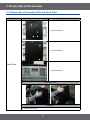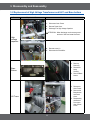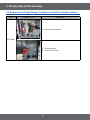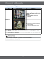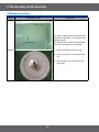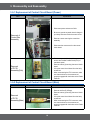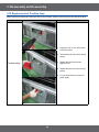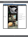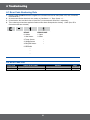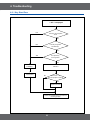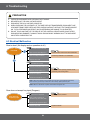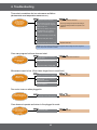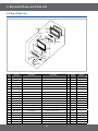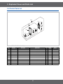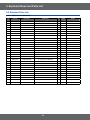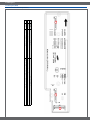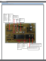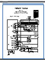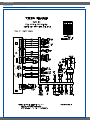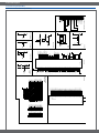
1
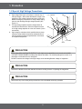
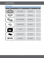
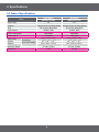
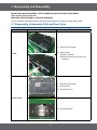
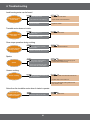
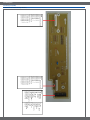
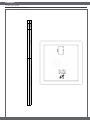
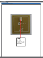
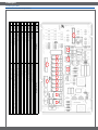
BASIC:
SMH7185BG
MODEL:
SMH9207ST
MODEL CODE: SMH9207ST/XAC
1. Precaution
2. Product Specification
3. Disassembly and Reassembly
4. Troubleshooting
5. Exploded Views and Part List
6. PCB Diagrams
7. Wiring Diagrams
8. Schematic Diagrams
Refer to the service manual in the GSPN(see rear cover) for the more information.
• Contents
1. Precaution. . . . . . . . . . . . . . . . . . . . . . . . . . . . . . . . . . . . . . . . . . . . . . . . . . . . . . . . . . . . . . . . . . . . . . . . . . . . . . 3
1-1 Safety precautions. . . . . . . . . . . . . . . . . . . . . . . . . . . . . . . . . . . . . . . . . . . . . . . . . . . . . . . . . . . . . . . . . . . . . 4
1-2 Special High Voltage Precautions . . . . . . . . . . . . . . . . . . . . . . . . . . . . . . . . . . . . . . . . . . . . . . . . . . . . . . . . . 5
2. Specifications . . . . . . . . . . . . . . . . . . . . . . . . . . . . . . . . . . . . . . . . . . . . . . . . . . . . . . . . . . . . . . . . . . . . . . . . . . . 6
2-1 Features. . . . . . . . . . . . . . . . . . . . . . . . . . . . . . . . . . . . . . . . . . . . . . . . . . . . . . . . . . . . . . . . . . . . . . . . . . . . . 6
2-2 Accessory. . . . . . . . . . . . . . . . . . . . . . . . . . . . . . . . . . . . . . . . . . . . . . . . . . . . . . . . . . . . . . . . . . . . . . . . . . . . 7
2-3 Table of Specifications. . . . . . . . . . . . . . . . . . . . . . . . . . . . . . . . . . . . . . . . . . . . . . . . . . . . . . . . . . . . . . . . . . 8
3. Disassembly and Reassembly. . . . . . . . . . . . . . . . . . . . . . . . . . . . . . . . . . . . . . . . . . . . . . . . . . . . . . . . . . . . . . 9
3-1 Disassembly of Assembly Grille and Panel Outer. . . . . . . . . . . . . . . . . . . . . . . . . . . . . . . . . . . . . . . . . . . . . 9
3-2 Replacement of High Voltage Transformer and HVC and Base bottom . . . . . . . . . . . . . . . . . . . . . . . . . . . 11
3-3 Replacement of Magnetron. . . . . . . . . . . . . . . . . . . . . . . . . . . . . . . . . . . . . . . . . . . . . . . . . . . . . . . . . . . . . 13
3-4 Replacement of Door Assembly. . . . . . . . . . . . . . . . . . . . . . . . . . . . . . . . . . . . . . . . . . . . . . . . . . . . . . . . . . 14
3-5 Replacement of Fuse. . . . . . . . . . . . . . . . . . . . . . . . . . . . . . . . . . . . . . . . . . . . . . . . . . . . . . . . . . . . . . . . . . 16
3-6 Replacement of Drive Motor . . . . . . . . . . . . . . . . . . . . . . . . . . . . . . . . . . . . . . . . . . . . . . . . . . . . . . . . . . . . 16
3-7 Replacement of stirrer motor. . . . . . . . . . . . . . . . . . . . . . . . . . . . . . . . . . . . . . . . . . . . . . . . . . . . . . . . . . . . 17
3-8 Removal of stirrer. . . . . . . . . . . . . . . . . . . . . . . . . . . . . . . . . . . . . . . . . . . . . . . . . . . . . . . . . . . . . . . . . . . . . 18
3-9-1 Replacement of Control Circuit Board (Power). . . . . . . . . . . . . . . . . . . . . . . . . . . . . . . . . . . . . . . . . . . . . 19
3-9-2 Replacement of Control Circuit Board (Main). . . . . . . . . . . . . . . . . . . . . . . . . . . . . . . . . . . . . . . . . . . . . . 19
3-10 Replacement of Cooktop lamp. . . . . . . . . . . . . . . . . . . . . . . . . . . . . . . . . . . . . . . . . . . . . . . . . . . . . . . . . . 20
3-11 Replacement of Oven Light. . . . . . . . . . . . . . . . . . . . . . . . . . . . . . . . . . . . . . . . . . . . . . . . . . . . . . . . . . . . 21
4. Troubleshooting . . . . . . . . . . . . . . . . . . . . . . . . . . . . . . . . . . . . . . . . . . . . . . . . . . . . . . . . . . . . . . . . . . . . . . . . 22
4-1 Error Code Numbering Rule. . . . . . . . . . . . . . . . . . . . . . . . . . . . . . . . . . . . . . . . . . . . . . . . . . . . . . . . . . . . . 22
4-2 Error Code List. . . . . . . . . . . . . . . . . . . . . . . . . . . . . . . . . . . . . . . . . . . . . . . . . . . . . . . . . . . . . . . . . . . . . . . 22
4-3 Electrical Malfunction. . . . . . . . . . . . . . . . . . . . . . . . . . . . . . . . . . . . . . . . . . . . . . . . . . . . . . . . . . . . . . . . . . 24
5. Exploded Views and Parts List . . . . . . . . . . . . . . . . . . . . . . . . . . . . . . . . . . . . . . . . . . . . . . . . . . . . . . . . . . . . 27
5-1 Exploded Views. . . . . . . . . . . . . . . . . . . . . . . . . . . . . . . . . . . . . . . . . . . . . . . . . . . . . . . . . . . . . . . . . . . . . . 27
5-2 Main Parts List. . . . . . . . . . . . . . . . . . . . . . . . . . . . . . . . . . . . . . . . . . . . . . . . . . . . . . . . . . . . . . . . . . . . . . . 28
5-3 Door Parts List. . . . . . . . . . . . . . . . . . . . . . . . . . . . . . . . . . . . . . . . . . . . . . . . . . . . . . . . . . . . . . . . . . . . . . . 30
5-4 Control Parts List. . . . . . . . . . . . . . . . . . . . . . . . . . . . . . . . . . . . . . . . . . . . . . . . . . . . . . . . . . . . . . . . . . . . . 31
5-5 Standard Parts List. . . . . . . . . . . . . . . . . . . . . . . . . . . . . . . . . . . . . . . . . . . . . . . . . . . . . . . . . . . . . . . . . . . . 32
6. PCB Diagrams. . . . . . . . . . . . . . . . . . . . . . . . . . . . . . . . . . . . . . . . . . . . . . . . . . . . . . . . . . . . . . . . . . . . . . . . . . 33
6-1 PCB Diagrams (ML9M) . . . . . . . . . . . . . . . . . . . . . . . . . . . . . . . . . . . . . . . . . . . . . . . . . . . . . . . . . . . . . . . . 33
7. Wiring Diagrams . . . . . . . . . . . . . . . . . . . . . . . . . . . . . . . . . . . . . . . . . . . . . . . . . . . . . . . . . . . . . . . . . . . . . . . . 39
7-1 Wiring Diagrams. . . . . . . . . . . . . . . . . . . . . . . . . . . . . . . . . . . . . . . . . . . . . . . . . . . . . . . . . . . . . . . . . . . . . . 39
8. Schematic Diagrams. . . . . . . . . . . . . . . . . . . . . . . . . . . . . . . . . . . . . . . . . . . . . . . . . . . . . . . . . . . . . . . . . . . . . 41
8-1 Schematic Diagrams (ML9-Main). . . . . . . . . . . . . . . . . . . . . . . . . . . . . . . . . . . . . . . . . . . . . . . . . . . . . . . . . 41
2
1. Precaution
3
1. Precaution
Follow these special safety precautions. Although the microwave oven is completely safe during ordinary use,
repair work can be extremely hazardous due to possible exposure to microwave radiation, as well as potentially
lethal high voltages and currents.
1-1 Safety precautions (
)
13. Design Alteration Warning: Use exact replacement
parts only, i.e.,only those that are specified in
thedrawings and parts lists of this manual. This
is especially important for the Interlock switches,
described above. Never alter or add to the
mechanical or electrical design of the MWO.
Any design changes or additions will void the
manufacturer’s warranty. Always unplug the unit’s
AC power cord from the AC power source before
attempting to remove or reinstall any component or
assembly.
14. Never defeat any of the B+ voltage interlocks. Do not
apply AC power to the unit (or any of its assemblies)
unless all solid-state heat sinks are correctly
installed.
15. Some semiconductor (“solid state”) devices
are easily damaged by static electricity. Such
components are called Electrostatically Sensitive
Devices (ESDs). Examples include integrated
circuits and field-effect transistors. Immediately
before handling any semiconductor components or
assemblies, drain the electrostatic charge from your
body by touching a known earth ground.
16. Always connect a test instrument’s ground lead to
the instrument chassis ground before connecting the
positive lead; always remove the instrument’s ground
lead last.
17. When checking the continuity of the witches or
transformer, always make sure that the power is
OFF, and one of the lead wires is disconnected.
18. Components that are critical for safety are indicated
in the circuit diagram by shading,
or
.
19. Use replacement components that have the same
ratings, especially for flame resistance and dielectric
strength specifications. A replacement part that does
not have the same safety characteristics as the
original might create shock, fire or other hazards.
NOTE : Connect the oven to a 20A. When
connecting the oven to a 15A,make sure that circuit
breaker can operate.
1. All repairs should be done in accordance with the
procedures described in this manual. This product
complies with Federal Performance Standard 21
CFR
2. Microwave emission check should be performed to
prior to servicing if the oven is operative.
3. If the oven operates with the door open :Instruct
the user not to operate the oven and contact
the manufacturer and the center for devices and
radiological health immediately.
4. Notify the Central Service Center if the microwave
leakage exceeds 5 mW/cm2.
5. Check all grounds.
6. Do not power the MWO from a “2-prong” AC cord.
Be sure that all of the built-in protective devices are
replaced. Restore any missing protective shields.
7. When reinstalling the chassis and its assemblies,
be sure to restore all protective devices, including:
nonmetallic control knobs and compartment covers.
8. Make sure that there are no cabinet openings
through which people --particularly children--might
insert objects and contact dangerous voltages.
Examples: Lamp hole,ventilation slots.
9. Inform the manufacturer of any oven foundto have
emission in excess of 5 mW/cm2 ,Make repairs to
bring the unit into compliance at no cost to owner
and try to determine cause. Instruct owner not to use
oven until it has been brought into compliance.
CENTRAL SERVICE CENTER
10. Service technicians should remove their watches
while repairing an MWO.
11. To avoid any possible radiation hazard,replace parts
in accordance with the wiring diagram. Also, use
only the exact replacements for the following parts:
Primary and secondary interlock switches, interlock
monitor switch.
12. If the fuse is blown by the Interlock Monitor Switch:
Replace all of the following at the same time:
Primary, door sensing switch and power relay, as
well as the Interlock Monitor Switch. The correct
adjustment of these switches is described elsewhere
in this manual. Make sure that the fuse has the
correct rating for the particular model being repaired.
4
1. Precaution
1-2 Special High Voltage Precautions
1. High Voltage Warning Do not attempt to measure any of
the high voltages --this includes the filament voltage of the
magnetron. High voltage is present during any cook cycle.
Before touching any components or wiring, always unplug
the oven and discharge the high voltage capacitor (See
Figure 1-1)
2. The high-voltage capacitor remains charged about 30
seconds after disconnection. Short the negative terminal
of the high-voltage capacitor to to the oven chassis. (Use a
screwdriver.)
3. High voltage is maintained within specified limits by closetolerance, safety-related components and adjustments. If
the high voltage exceeds the specified limits, check each
of the special components.
H . V . Capacitor
H . V . Diode
Short
PRECAUTION
There exists HIGH VOLTAGE ELECTRICITY with high current capabilities in the circuits of the HIGH
VOLTAGE TRANSFORMER secondary and filament terminals. It is extremely dangerous to work on or
near these circuits with the oven energized.
DO NOT measure the voltage in the high voltage circuit including filament voltage of magnetron.
PRECAUTION
Servicemen should remove their watches whenever working close to or replacing the magnetron.
PRECAUTION
Never touch any circuit wiring with your hand nor with uninsulated tool during operation.
5
2. Specifications
2-1 Features
Product Features
• Professional Design
Samsung New OTR with Stainless Steel, it has professional look
and the design matches great with other kitchen appliances, so that
it provides harmonious kitchen interior and finally completes total
kitchen solution.
• Turbo vent
With 400CFM ventilation power, New OTR can keep the comfortable
cooking condition by absorbing smoke and odor from cook-top.
Moreover, it provides the silent condition that is equivalent noise
level to other OTR with lower ventilation power.
The Strongest power without additional noise!
That’s the benefit you can feel from New OTR!
• Big Interior capacity for
convenience
With the 2.0 cu.ft capacity, it offers enough space to cook.
The big capacity combined with 1,100 watts of output achieves
superior cooking results.
• Sensor cook
Don’t worry about failure of your cooking!
New OTR’s sensor technology offers the best dish.
Only thing you need to do is just select the cooking menu, and then
you will be satisfied with the cooking results by sensor cook.
• VFD display
With more informative VFD display, the OTR helps you use all the
function it has with ease.
6
2. Specifications
2-2 Accessory
Item
Description
Code No.
Q’ty
TRAY COOKING
DE74-20002A
1
ASSY-GUIDE ROLLER
DE97-00637A
1
ASSY-HOOD DAMPER
DE92-90242D
1
ASSY-HARD WARE
DE92-90505E
1
FILTER AIR
DE63-30011A
2
FILTER CHARCOAL
DE63-00367D
1
RACK-WIRE
DE75-00036B
1
7
2. Specifications
2-3 Table of Specifications
Items
Oven Cavity
Controls
Timer
Power Source
Basic Model
New Model
SMH9207ST/XAA
SMH9207ST/XAC
2.0
10 power levels, including defrost
2.0
10 power levels, including defrost
99 minutes, 99seconds
99 minutes, 99seconds
120VAC, 60Hz
120VAC, 60Hz
1650 Watts
1500 Watts
Power consumption
1100 Watts
Power Output
Oven Cavity
Outside
Shipping
Net/Gross Weight
Export Zone
1/32
Dimensions
(W x H x D inches)
22
7/8
x 10
1000 Watts
7/8
x 14
22
1/32
x 107/8 x 147/8
297/8 x 161/2 x 161/2
297/8 x 161/2 x 161/2
333/8 x 205/32 x 1913/32
333/8 x 205/32 x 1913/32
52.7lbs / 60.6lbs
USA
52.7lbs / 60.6lbs
Canada
8
3. Disassembly and Reassembly
MAGNETRON, MOTOR ASSEMBLY, VENT BLOWER AND HIGH VOLTAGE TRANSFORMER
Oven must be removed from wall.
REMOVING OVEN FROM WALL (2 PEOPLE REQUIRED)
Oven is hooked on metal tabs at bottom of wall mounting plate and to cabinet by (3) top cabinet bolts.
3-1 Disassembly of Assembly Grille and Panel Outer
Parts
Explaination Photo
Explaination
1. Disconnect oven power.
2. Remove Grille.
1) Remove 2 screws
2) Slide the Grille to the left, then pull it
straght out.
Grille
1. Disconnect oven power.
2. Remove Grille.
3. Remove Screw.(7)
Panel Outer
4. Remove Screw.(4)
9
3. Disassembly and Reassembly
3-1 Disassembly of Assembly Grille and Panel Outer
Parts
Explaination Photo
Explaination
5. Remove Screw.(4)
6. Remove Screw.(2)
Panel Outer
7. Remove Screw.(2)
Explaination Photo
Explaination
8. Remove Panel Outer.
10
3. Disassembly and Reassembly
3-2 Replacement of High Voltage Transformer and HVC and Base bottom
Parts
Explaination Photo
Explaination
1. Disconnect Oven Power.
2. Remove Panel Outer.
3. Discharge The High Voltage Capacitor.
ATTENTION : W
hen discharge must become ground
terminal of HVC and metal of around.
High
voltage
capacitor
4. Remove screw.(1)
5. Disconnect the Lead Wire.
Base
Bottom
1. Remove
Screw.(5)
2. Disconnect
Lamp
Housing.
3. Remove Base
bottom.
HV Trans
1. Disconnect
Oven Power.
2. Remove the
Base bottom
and Panel
Outer.
3. Disassembly
the Bracket
Duct upper
after remove
screw.
11
3. Disassembly and Reassembly
3-2 Replacement of High Voltage Transformer and HVC and Base bottom
Parts
Explaination Photo
Explaination
4. Disconnect the Lead Wire.
HV Trans
5. Remove screw.(4)
6. Take out the HV Trans.
12
3. Disassembly and Reassembly
3-3 Replacement of Magnetron
Parts
Explaination Photo
Explaination
Remove the magnetron including the shield
case, permanent magnet, choke coils and
capacitors (all of which are contained in one
assembly).
1. Disconnect all lead wires from the
magnetron.
Magnetron
2. Remove nuts (4) securing the magnetron
to the wave guide.
3. Take out the magnetron very carefully.
NOTE1: W
hen removing the magnetron, make sure that it antenna does not hit any adjacentparts, or it may be
damaged.
NOTE2: W
hen replacing the magnetron, be sure to remount the magnetron gasket in the correct position and make
sure the gasket is in good condition.
PRECAUTION
During replacement, be certain R.F. anode gasket is in place around anode stub.
PERFORM MICROWAVE LEAKAGE TEST
13
3. Disassembly and Reassembly
3-4 Replacement of Door Assembly
Parts
Disassembly Photo
Explaination
Removal of
Door Assembly
1. Disconnect the lead wire.
2. Open the Assembly Door by degree 90º
3. Seperate lifting Assembly Door from Set.
Removal of
Door C
4. Insert flat screwdriver into the gap between Door
“A” and Door “C” to remove Door “C”.
• Becareful when handling Door “C” because it is
fragile.
Removal of Key
Door & Spring
5. Detach the spring and key door from Door.
14
3. Disassembly and Reassembly
3-4 Replacement of Door Assembly
Removal of
Handle
4. Remove 2 screws, then handle is detached from
Door “A”.
Removal of
Door “E”
5. Following the procedure as shown in the figure,
insert and bend a thin metal plate between Door
“E” and Door “A” until you hear the ‘tick’ sound.
• Insertion depth of the thin metal plate should be
0.5mm or less.
6. Remove 4 screw securing Door “E” to Door “A”.
PRECAUTION
PERFORM MICROWAVE LEAKAGE TEST
15
3. Disassembly and Reassembly
3-5 Replacement of Fuse
Parts
Explaination Photo
Explaination
The fuse is located on the noise filter.
1. Disconnect power and remove grilleand
Assembly Control Box.
2. Replace the fuse.
3. When 20A fuse blows out by the operation
of interlock monitor switch failure, replace
the primary interlock switch, secondary
interlock switch, door sensing switch,
interlock monitor switch and power relay.
4. When the above four switches operate
properly, check if any other part such as the
control circuit board, blower motor or high
voltage transformer is defective.
Fuse
Fuse
Fuse
3-6 Replacement of Drive Motor
Parts
Explaination Photo
Explaination
1. Disconnect power and remove Base
bottom screws(5).
2. Remove Base bottom and disconnect the
turntable motor drive.
3. Remove turntable motor screws(1) and pull
the turntable motor out.
4. When replacing the drive motor, be sure to
remount it in the correct position with the
coupler.
5. Connect all the leads to the drive motor.
Drive
Motor
16
3. Disassembly and Reassembly
3-7 Replacement of stirrer motor
Parts
Explaination Photo
Explaination
1. Disconnect power and remove Grille
screws(3).
2. Remove the bracket duct upper.
Stirrer Motor
3. Disconnect the stirrer motor wire.
4. Remove stirrer motor screws(1) and after turn
to arrow direction pull the stirrer motor.
17
3. Disassembly and Reassembly
3-8 Removal of stirrer
Parts
Explaination Photo
Explaination
The stirrer is motor driver and located on the
upper side of the cavity. The oven uses a top
feed wave guide.
The stirrer is located in the wave guide and
the motor is located on the wave guide.
1. Disconnect power and open the door.
Stirrer
2. Remove the clip and turn the stirrer cover
left.
3. Remove stirrer cover and the stirrer will
come with it.
18
3. Disassembly and Reassembly
3-9-1 Replacement of Control Circuit Board (Power)
Parts
Explaination Photo
Explaination
1. Disconnect power and remove Grille.
2. Be sure to ground any static electric charge in
your body and never touch the control circuit.
Removal of
Control Box
Assembly
3. Remove a screw securing the control box
assembly.
4. Disconnect the connectors from the control
circuit board.
1. Pull the lever end of the plastic fastener and
remove the Flexible Printed Circuit(FPC) of
membrane panel.
2. Remove screws (3) securing the control circuit
board.
3. Lift up the control circuit board from the Ass’y
control box.
4. When reconnecting the FPC connector, make
sure that the holes on the connector are
properly engaged with the hooks on the Plastic
Fastener.
Removal
of P.C.B
Assembly(Sub)
3-9-2 Replacement of Control Circuit Board (Main)
Parts
Explaination Photo
Explaination
1. Remove the Door-E(15Page)
2. Remove screws (3) securing the control circuit
board.
3. Lift up the control circuit board from the Ass’y
control box.
4. When reconnecting the FPC connector, make
sure that the holes on the connector are
properly engaged with the hooks on the Plastic
Fastener.
Removal
of P.C.B
Assembly(Main)
19
3. Disassembly and Reassembly
3-10 Replacement of Cooktop lamp
When replacing the night light, make sure that you are wearing gloves to avoid injury from the heat of the bulb.
Parts
Explaination Photo
Explaination
1. Unplug the oven or turn off the power
at the main power.
2. Remove the bulb cover, and mounting
screws.
3. Replace the bulb with a 40 watt
appliance bulb.
Cooktop Lamp
4. Replace the bulb cover and mounting
screws.
5. Turn the power back on at the main
power supply.
20
3. Disassembly and Reassembly
3-11 Replacement of Oven Light
Parts
Explaination Photo
Explaination
1. Disconnect Oven power.
2. Remove the Grille
Oven Light
3. Remove the bracket Duct upper by
remove 1 screw.
4. Replace the bulb with a 40 watt
appliance bulb.
21
4. Troubleshooting
4-1 Error Code Numbering Rule
1. ERROR CODE NUMBERING RULE is applied to a microwave oven and an oven.(CMO, OTR, Grill, Convection,
Commercial etc.)
2. All sensors and devices have their own number. ex) Gas Sensor = 1, Temp. Sensor = 2, ...
3. Of each device, No.1 and No.2 refer to “Open Error” (not sensed) and “Short Error”, respectively.
4. This numbering rule has been applied to models to have been developed since January, 1, 2005. (But, GE or
Customize model are excluded.)
DEVICE
ERROR CASE
0- Others
1- Open
1- Gas Sensor
2- Short
2- Temp. Sensor
•
3- Weight Sensor
•
4- Easy/PH Sensor
•
5- EEPROM
•
•
•
4-2 Error Code List
Error Code
-SE-
Others (E-0X, Letter)
Key Short Error (10 seconds)
22
Solution
Page
Turn off set and restart.
21 Page
4. Troubleshooting
4-2-1 Key Short Error
“- SE -” is displayed.
YES
Is the key not recognized
at all?
NO
YES
Is the key recognized
intermittently?
NO
Is a specific key
not recognized?
YES
NO
The membrane
is defective.
Replace the
Control Panel.
S/W Error
After Power > On,
does the symptom continue?
NO
YES
Replace the PCB.
Perform the operation again and check if it
is working properly.
23
4. Troubleshooting
PRECAUTION
1.
2.
3.
4.
CHECK GROUNDING BEFORE CHECKING FOR TROUBLE.
BE CAREFUL OF THE HIGH VOLTAGE CIRCUIT.
DISCHARGE THE HIGH VOLTAGE CAPACITOR.
WHEN CHECKING THE CONTINUITY OF THE SWITCHES OR TRANSFORMER, DISCONNECT ONE
LEAD WIRE FROM THESE PARTS AND THEN CHECK CONTINUITY WITHOUT THE POWER SOURCE
ON. TO DO OTHERWISE MAY RESULT IN A FALSE READING OR DAMAGE TO YOUR METER.
5. DO NOT TOUCH ANY PART OF THE CIRCUIT OR THE CONTROL CIRCUIT BOARD, SINCE STATIC
DISCHARGE MAY DAMAGE IT. ALWAYS TOUCH GROUND WHILE WORKING ON IT TO DISCHARGE
ANY STATIC CHARGE BUILT UP.
4-3 Electrical Malfunction
Oven is dead. (No display and no operation at all.)
Open or loose lead wire harness
Fuse is OK
Open thermal cutout (Magnetron)
Check fan motor when thermal cutout is defective.
Open low voltage transformer
Check Ass’y PCB when L.V.T is defective.
Defective Ass’y PCB
Shorted lead wire harness
Defective primary latch switch (NOTE
(NOTE 1)
1)
Defective monitor switch (NOTE
(NOTE 1)
1)
Check adjustment of primary, interlock monitor,
power relay, door sensing switch.
Shorted H.V.Capacitor
Shorted H.V.Transformer (NOTE
(NOTE 2)
2)
NOTE 1: All of these switches must be replaced at the same time. (refer to adjustment instructions)
Check continuity of power relay contacts and if it has continuity, replace power relay also.
NOTE 2: When H.V.Transformer is replaced, check diode and magnetron also.
Oven does not accept key input (Program)
Oven does not
accept key input
Key input is not in-Sequence
Refer to operation procedure.
Open or loose connection of
membrane key pad to Ass’y PCB
Shorted or open membrane panel
Timer starts
countdown but
no microwave
Defective Ass’y PCB
Replace PCB main.
Off-alignment of latch switches
24
Adjust door and latch switches.
Open or loose connection of high
Check high voltage component according to
Oven does not
accept key input
Open or loose connection of
membrane key pad to Ass’y PCB
4. Troubleshooting
Shorted or open membrane panel
Defective Ass’y PCB
Replace PCB main.
Timer starts countdown but no microwave oscillation.
(No heat while oven lamp and fan motor turn on.)
Timer starts
countdown but
no microwave
oscillation
Off-alignment of latch switches
Adjust door and latch switches.
Open or loose connection of high
voltage circuit especially magnetron
filament circuit (NOTE)
Check high voltage component according to
component test procedure and replace if it is
defective.
Defective high voltage components
H.V.Transformer H.V. Capacitor
H.V.Diode, H.V.Fuse Magnetron
Open or loose wiring of power relay
Defective primary latch switch
Defective power relay or Ass’y PCB
Replace PCB main.
NOTE: Large contact resistance will bring lower magnetron filament voltage and cause magnetron
to lower output and/or intermittent oscillation.
Oven can program but timer does not start.
Oven can program
but timer does
not start
Oven can program
but timer does
not start
Oven can program
but timer does
Oven not
canstart
program
but timer output
does
Microwave
not start
Microwave
output is low
is low.
Microwave
output is low
Microwave
output is low
Microwave
output is low
Fan motor turns
on when plugged in
Open or loose wiring of secondary
interlock switch
Adjust door and interlock switches.
Open or looseof
wiring
of secondary
Off-alignment
primary
interlock
interlock switch
Adjust door and interlock switches.
Open
or loose
wiring interlock
of secondary
Defective
secondary
S/W
Off-alignment
of primary
interlock
interlock switch
Open or loose wiring of secondary
interlock
Off-alignment
of primary
interlock
Defectiveswitch
secondary
interlock
S/W
Decrease
power source
voltage
(Oven
takesinlonger
time
to cook
Off-alignment of primary interlock
Defective secondary interlock S/W
Open or loose wiring of magnetron
Decrease
in power source voltage
filament
Defectivecircuit.
secondary interlock S/W
(Intermittent oscillation)
Open
or loose
wiring
of magnetron
Decrease
in power
source
voltage
filament
Aging of circuit.
magnetron
(Intermittent
Decrease
in oscillation)
power
source
voltage
Open
or loose
wiring
of magnetron
filament circuit.
Aging or
of loose
magnetron
Open
wiring of magnetron
(Intermittent
oscillation)
filament circuit.
(Intermittent
oscillation)
Aging
magnetron
Loose of
wiring
of door sensing switch
Adjust door and interlock switches.
Fan motor turns on when plugged
in.
Aging of magnetron
Fan motor turns
on when plugged in
Fan motor turns
on when plugged in
Fan
motor
Oven
doesturns
not
on when
plugged
operate
and
return in
to
the plugged
Oven
does not
in mode
operate and return to
Oven
does
not operate
the plugged
Oven
does not
in mode
operate and return to
Oven
does not
the plugged
operateinand
return to
mode
Loud
buzzing
noise
the plugged
can
be
heard
in mode
Loud buzzing noise
can be heard
Loud buzzing noise
can be heard
Loud buzzing noise
can be heard
Turntable motor does
not rotate.
Adjust door and interlock switches.
Consult electrician.
food.)
Consult electrician.
Consult electrician.
Consult electrician.
Consult electrician.
Loose wiring of door sensing switch
Consult electrician.
Loose wiring of door sensing switch
Consult electrician.
Loose wiring of door sensing switch
Defective Ass’y PCB
Consult electrician.
Replace PCB main.
Defective
and return
to Ass’y
the PCB
plugged in mode. Replace PCB main.
Defective Ass’y PCB
Loose fan and fan motor
Defective Ass’y PCB
Replace PCB main.
Tighten screws of fan motor.
Replace PCB main.
Loose
Loose screws
fan and on
fanH.V.Transformer
motor
Tighten screws
screws of
of fan
H.V.Transformer.
Tighten
motor.
Shorted
H.V.Diode
Loose
screws
fan
and on
fanH.V.Transformer
motor
Replace
H.V.Diode.
Tighten screws
of fan
motor.
H.V.Transformer.
Loose fan and fan motor
Loose
screws
on H.V.Transformer
Shorted
H.V.Diode
Tighten screws of fan motor.
Tighten
of H.V.Transformer.
Replacescrews
H.V.Diode.
Loose
screws
H.V.Transformer
Open or
loose on
wiring
of
Shorted H.V.Diode
turntable motor.
25
Tighten
of H.V.Transformer.
Replacescrews
turntable
motor.
Replace H.V.Diode.
Shorted
Open or H.V.Diode
loose
wiring
of
Defective
turntable
motor
Replace H.V.Diode.
Replace turntable motor.
Loose wiring of door sensing switch
(Intermittent
oscillation)
on when plugged in
Aging of magnetron
Fan motor turns
Loose wiring of door sensing switch
on when plugged in
Aging of magnetron
Fan motor turns
Loose wiring of door sensing switch
on when plugged in
Oven does not
Fan motor
turns to
operate
and return
Loose
wiring
of door
Defective
Ass’y
PCB sensing switch
onOven
when
plugged
does
not in
the plugged
Fan
motor
turns
operateinand
return to
mode
Loose
wiring
of door
Defective
Ass’y
PCB sensing switch
onOven
when
plugged
does
not in
the plugged
Loud
buzzing
noise
operate
return
to can be heard.
inand
mode
Defective Ass’y PCB
Oven
does not
the plugged
operateinand
return to
mode
Defective Ass’y PCB
the plugged
Loose fan and fan motor
Oven
does not
inand
mode
Loud buzzing
noise
operate
return
to
Defective
PCB
Loose fan Ass’y
and fan
motor
can
be
heard
Oven
does
not
the plugged
Loose screws on H.V.Transformer
Loud buzzing
noise
operate
return
to
inand
mode
Defective
Ass’y
PCB
Loose fan and fan motor
can
be heard
the plugged
Loose screws on H.V.Transformer
Loud buzzing
Shorted H.V.Diode
in mode noise
Loose fan and fan motor
can be heard
Loose screws on H.V.Transformer
Loud buzzing noise
Shorted H.V.Diode
can be heard
Loose screws
fan and on
fanH.V.Transformer
motor
Shorted H.V.Diode
Turntable
motor
does not rotate.
Loud buzzing
noise
Open or
loose
of
Loose
fan
and wiring
fan motor
can be heard
Loose
screws
on H.V.Transformer
Shorted
H.V.Diode
turntable
motor.
Loud
buzzing
noise
Turntable motor does
Open or loose wiring of
can
heard
notbe
rotate.
Loose
screws
on H.V.Transformer
turntable
motor.
Defective
turntable motor
Shorted H.V.Diode
Turntable motor does
Open or loose wiring of
not rotate.
turntable
motor.
Defective
turntable motor
Shorted H.V.Diode
Turntable motor does
Open or loose wiring of
not rotate.
turntable
motor.
Defective turntable motor
Turntable motor does
Open
wiring
of
not rotate.
Open or
or loose
loose
wiring
of primary
Defective
turntable
motor
turntable
motor.
interlock
switch
Turntable
motor
does
Oven
stops
operation
during
cooking.
Oven stops operation
Open
or
loose
wiring
Open or loose wiring of
of primary
not rotate.
during
cooking
turntable
motor.
Defective
turntable
motor
Turntable
motor
does
interlock switch
Operation
of thermal
cutout (Magnetron)
Oven
stops
operation
Open or loose wiring of primary
not rotate.
during
cooking
Defective
turntable
motor
interlock switch
Operation
of thermal
cutout (Magnetron)
Oven stops operation
Open or loose wiring of primary
during cooking
interlock switch
Operation
of thermal cutout (Magnetron)
Oven stops operation
Open or loose wiring of primary
during cooking
Metallic ware
or cooking
dishes
Operation
of thermal
cutout
(Magnetron)
interlock switch
Oven stops operation
touching
on thewiring
oven of
wall
Open
or
loose
primary
Sparks
Metallic ware or cooking dishes
during
cooking
interlock switch
Operation
ofthe
thermal
(Magnetron)
Sparks.
Oven stops operation
touching ware
on
oven cutout
wall
Ceramic
trimmed
with gold
or
Sparks
Metallic
ware or
cooking
during
cooking
silver
powder
also
causesdishes
sparks
4. Troubleshooting
Sparks
Sparks
Uneven
cooking
Sparks
Uneven
cooking
Sparks
Uneven
cooking
Uneven
cooking.
Uneven cooking
Uneven cooking
Uneven cooking
Noise from the
turntable motor when
Noiseto
from
the
it starts
operate.
turntable motor when
Noiseto
from
the
it starts
operate.
turntable motor when
Noiseto
from
the
it starts
operate.
turntable
motor
Noise
from
thewhen
turntable
it starts
operate.
Noiseto
from
the
turntable motor when
Noiseto
from
the
it starts
operate.
turntable motor when
it starts to operate.
Operation
ofthe
thermal
(Magnetron)
touching ware
on
oven cutout
wall
Ceramic
trimmed
with gold
or
Metallic
ware or
cooking
silver
powder
also
causesdishes
sparks
touching ware
on thetrimmed
oven wall
Ceramic
with gold or
silver
powder
also
causesdishes
sparks
Metallic
ware or
cooking
Ceramic
ware trimmed
with golddue
or
Uneven intensity
of microwave
touching
on the oven
wall
silver
powder
also
causesdishes
sparks
Metallic
ware or
cooking
to its characteristics
Uneven intensity
of microwave
touching
on thetrimmed
oven
wall
Ceramic
ware
with golddue
or
to its characteristics
silver
powder also causes sparks
Uneven intensity
of microwave
Ceramic
ware trimmed
with golddue
or
to its characteristics
silver
powder also causes sparks
Uneven intensity of microwave due
to its characteristics
Uneven intensity of microwave due
to its characteristics
Uneven intensity of microwave due
to its characteristics
Noise may result from the motor
Noise may result from the motor
Noise may result from the motor
Consult electrician.
Consult electrician.
Consult electrician.
Consult
Replaceelectrician.
PCB main.
Consult
Replaceelectrician.
PCB main.
Replace PCB main.
Replace PCB main.
Tighten screws of fan motor.
Replace
PCB main.
Tighten screws
of fan motor.
Tighten screws of H.V.Transformer.
Replace
PCB
main.
Tighten screws of fan motor.
Tighten screws of H.V.Transformer.
Replace H.V.Diode.
Tighten screws of fan motor.
Tighten screws of H.V.Transformer.
Replace H.V.Diode.
Tighten
motor.
Tighten screws
screws of
of fan
H.V.Transformer.
Replace H.V.Diode.
Tighten
of fan
motor.
Replacescrews
turntable
motor.
Tighten
of H.V.Transformer.
Replacescrews
H.V.Diode.
Replace turntable motor.
Tighten screws of H.V.Transformer.
Replace H.V.Diode.
Replace turntable motor.
Replace H.V.Diode.
Replace turntable motor.
Replace
turntable
motor.
Adjust door
and latch
switches.
Replace
turntable
motor.
Adjust door
and latch
switches.
Adjust door and latch switches.
Adjust door and latch switches.
Adjust door and latch switches.
Inform the customer: Do not use any type of
cookware
with
trimming
Adjust door
andmetallic
latch switches.
Inform the customer: Do not use any type of
cookware with metallic trimming
Inform the customer: Do not use any type of
cookware with metallic trimming
Inform the customer: Do not use any type of
cookware with metallic trimming
Inform the customer: Do not use any type of
Wrap thinner
of the
food with aluminum foil.
cookware
withparts
metallic
trimming
Inform the customer: Do not use any type of
Wrap thinner
of the
food with aluminum foil.
cookware
withparts
metallic
trimming
se plastic wrap or cover with a lid.
Wrap thinner parts of the food with aluminum foil.
se plastic wrap or cover with a lid.
Stir once or twice while cooking foods such as
Wrap thinner parts of the food with aluminum foil.
soup,
cocoa,
or or
milk.
se
plastic
wrap
cover with a lid.
Stir once or twice while cooking foods such as
Wrap
thinner
parts
of thewith
fooda with
soup,
cocoa,
or
milk.
se
plastic
wrap
or
cover
lid. aluminum foil.
Stir once or twice while cooking foods such as
Wrap
parts
of the food with aluminum foil.
soup, thinner
cocoa, or
milk.
se
wrap
or while
covercooking
with a lid.
Stirplastic
once or
twice
foods such as
soup,
cocoa,
or milk.
Replace
turntable
motor.
se plastic wrap or cover with a lid.
Stir once or twice while cooking foods such as
Replace turntable motor.
soup, cocoa, or milk.
Stir once or twice while cooking foods such as
Replace turntable motor.
soup, cocoa, or milk.
may it
result
from the
motorNoise
when
starts
to motor
operate.
Replace turntable motor.
Noise may result from the motor
Replace turntable motor.
Noise may result from the motor
Replace turntable motor.
26
5. Exploded Views and Parts List
5-1 Exploded Views
M060
P007
U008
P012
M061
G361
T001
P036
P039
P025
P124
M444
P105
P086
M015
M036
T030
M067
P024
P034
H093
M102
C309
P001
P226
M001
M024
M040
H024
M068
P106
M528
M039 M527
M017
M059
C144
M087
M034
H096
M059
W002
W004
M023
M049
M036
P059
M102
M102
M035 M443
P121
B022
B064
B048
M038
U060
M444
M453
U005
B047
B048
U057
U001
M048
27
M155
B013
P109
M021
5. Exploded Views and Parts List
5-2 Main Parts List
(S.N.A : SERVICE NOT AVAILABLE)
No.
Code No.
Description
Specification
Q’ty
SA/SNA
Remark
B013
DE66-90106B
LEVER SWITCH-LOWER
OTR6,PP,T1.4,-,-,-,-,
1
SA
-
B022
DE96-00414A
ASSY BODY LATCH
RVM-1625BJ,-
1
SA
-
B047
3405-001033
SWITCH-MICRO
125/250VAC,16A,200gf,SPST-N
1
SA
-
B048
3405-001034
SWITCH-MICRO
125/250VAC,16A,200gf,SPST-N
2
SA
-
B064
DE66-00168A
LATCH-BODY
MODULAR-2,PP,-,-,-,-,-
1
SA
-
C144
DE66-20095B
BUTTON-LOCKING
-,-,OTR5,-,-,TB53)
1
SA
C309
DE59-50002A
C-FILM,LEAD-OTHER
10000nF,+10/-5%,220V,#
1
SA
-
G361
DE92-90508A
ASSY HOLDER-NUT
OTR6
1
SA
-
H024
DE60-30015A
NUT-FLANGE
-,MSWR10,P0.8,-,-,-,FEFZY,-,-
4
SA
-
H093
DE61-01181A
BRACKET-CONNECTOR
SMH9207,SECC,T0.5,-,-,
1
SNA
-
H096
DE31-90051A
BLADE-FAN
-,PP,-,D130,-,T,-
1
SA
-
M001
DE64-00754J
PANEL-OUTER
MAYTAG2.0,SECC,T0.4,BLACK
1
SA
-
M015
DE96-00218A
ASSY POWER CORD
UL,Straight,125V/15A,SJT
1
SC
-
M017
DE96-00400D
ASSY NOISE FILTER
-,SN-UF12D,250V/20A,SE
1
SA
-
M021
DE97-00365L
ASSY COVER MOTOR
W/POOL 2.0 GLIDE,-,-,PP
1
SNA
-
M023
DE31-00044B
MOTOR FAN
SMF-U4205A,120V/60Hz,2820rpm,A
1
SNA
-
M024
DE31-00029C
MOTOR VENTILATION
SMV-460UA1-AL,120V,60H
1
SNA
-
M034
DE67-00251A
COUPLER
SMH9207,SPS,-,-,-,-
1
SA
-
M035
OM75P(10)ESGN
ASSY-MGT
1
SA
-
M036
4713-001013
LAMP-INCANDESCENT
130V,40W,ORG,25X73
1
SA
-
M036
4713-001013
LAMP-INCANDESCENT
130V,40W,ORG,25X73
2
SA
-
M038
DE26-00151A
TRANS H.V
SHV-U1850A,120V,60Hz,2310,2460
1
SA
-
M039
2501-001035
C-OIL
860nF,2100V,BK,35x54x75,20mm
1
SA
-
M040
DE61-00115A
BRACKET-HVC
SMH7175,SECC,T0.6,-,-,-,-
1
SA
-
M048
DE61-00905A
BASE-PLATE
MAYTAG2.0,SECC,T0.6
1
SA
-
M049
DE31-10172B
MOTOR SYNCHRONOUS
SM16FBY36P1AW3,OTR,FRE
1
SA
-
M059
DE61-00375A
HOLDER-RACK
OTR-1.5CUFT,PP,-,-,-,-,-
4
SA
-
M060
DE92-90505E
ASSY HARD WARE
SMH7175,-,-
1
SC
-
M061
DE63-00367D
FILTER-CHARCOAL
SMH7175,AL,CARBON,T9,W15
1
SC
-
M067
DE94-02100A
ASSY GRILLE
SMH9207,PC,STS
1
SA
-
M068
DE64-02216A
GRILLE
SMH9207,PC,-,-,-,-,BLK,-
1
SA
-
M087
DE71-60121A
COVER-STIRRER
-,PP,T2.0,W7,L198,-,-,85G,
1
SA
-
M102
DE47-00006A
SOCKET-LAMP
-,OTR7,-,250V,75W,-,250Vx187
2
SA
-
M102
DE47-00006A
SOCKET-LAMP
-,OTR7,-,250V,75W,-,250Vx187
1
SA
-
M155
DE97-00677B
ASSY BASE PLATE
MMV5207,-,T0.6,BASE-PLAT
1
SA
-
M443
DE47-20007A
THERMOSTAT
NT-101,250V 10A/125V 15A,150(
1
SA
-
M444
DE47-20059A
THERMOSTAT
-,NT-101,250V 10A/125V 15A,-,
1
SA
-
M444
DE47-20059A
THERMOSTAT
-,NT-101,250V 10A/125V 15A,-,
1
SA
-
M453
DE47-20034A
THERMOSTAT
-,NT-101,250V 10A/125V 15A,-,
1
SA
-
M527
DE59-00002A
DIODE-H.V
MWO ALL,2CL4512H,-,450mA 13KV,
1
SC
-
M528
DE91-70063D
ASSY HVD
MWO-GE,HV03-12,-,-,RED,-
1
SA
-
P001
DE94-02101A
ASSY STIRRER
SMH9207,ALP T0.5
1
SA
-
P007
DE70-00561A
PLATE-MOUNTING
GE 1.6 NEW APPEARANCE,GI,
1
SA
-
P012
DE92-90242D
ASSY-HOOD DAMPER
JVM-1870,-,JVM250BL OTR
1
SA
-
28
5. Exploded Views and Parts List
5-2 Main Parts List (Continued)
(S.N.A : SERVICE NOT AVAILABLE)
No.
Code No.
Description
Specification
Q’ty
SA/SNA
Remark
P024
DE32-60011A
SENSOR GAS
TGS-880,-,-,-,-,-,-,-,-
1
SC
-
P025
DE61-90111A
HOLDER-SENSOR
-,POM(DURACON-M90-02),-,-,
1
SA
-
P034
DE97-00366H
ASSY DUCT UPPER
SMH9207,FH44N,SENSOR
1
SA
-
P036
DE39-40678D
WIRE HARNESS-S
SMH7185WG/XAA,120V60HZ,86
1
SA
-
P039
DE67-00168B
DUCT-UPPER
SMH7175,PP,BLK,T2.0
1
SA
-
P059
DE63-00419A
COVER-FRONT
MAYTAG2.0,SECC,T0.6,MAYTAG
1
SA
-
P086
DE61-01008A
BRACKET-BARRIER
MHC4/5,SECC,0.5,-,-,-,-
1
SA
-
P105
DE61-00410A
BRACKET-DUCT(U)
SMH7175,SECC,T0.5,W200,L
1
SA
-
P106
DE63-00601A
EARTH-GRILLE
SMH9207,STS301,T0.15,-,-,-,
1
SA
-
P109
DE63-00141B
COVER-MOTOR
AMV5206BAB,PP(V0 ),MAYTAG 2.
1
SA
-
P121
DE61-00411B
BRACKET-DUCT REAR
NEW WAVE / MT 2.0,SECC
1
SA
-
P124
DE60-30063A
NUT-MOUNTING
-,S10C,M6.3,-,-,-,ZNC,-,-
2
SA
-
P226
DE64-02222A
INLAY-GRILLE
SMH9207,STS430,T0.4,-,-,-,-
1
SA
-
T001
DE74-20002A
TRAY-COOKING
-,GLASS,T6,NEG,PI360,1.2CUF
1
SC
-
T030
DE75-00036B
RACK-WIRE
SMH7175,SNCR,W315,D4
1
SA
-
U001
DE94-02136B
ASSY BASE BOTTOM
SMH9207ST/XAC,SECC,T0.4
1
SA
-
U005
DE67-40063A
GLASS-COOK TOP LAMP
-,GLASS,T3.2,W59,L15
1
SA
-
U008
DE63-30011A
FILTER-AIR
-,AL,
2
SA
-
U057
DE63-00100B
COVER-COOKTOP LAMP
OTR-9,SECC,T0.4,-,-,-
1
SC
-
U060
DE61-01179B
BASE-BOTTOM
SMH9207ST/XAA,SECC,T0.4,BLAC
1
SA
-
W002
DE96-00785B
ASSY WIRE HARNESS-A
SMH9207,120V/60Hz,MO
1
SNA
-
W004
DE96-00787A
ASSY WIRE HARNESS-C
SMH9207,120V/60Hz,MO
1
SA
-
29
5. Exploded Views and Parts List
5-3 Door Parts List
D049
D005
D004
D037
C003
D006
D011
C004
D184
C009
D007
D002
Z779
W005
D063
D077
D064
D003
D073
D195
(S.N.A : SERVICE NOT AVAILABLE)
No.
Code No.
Description
Specification
Q’ty
SA/SNA
Remark
C003
C004
DE92-02135A
ASSY PCB-MAIN
RAS-ML9M-00,SMH9207ST/XAA,
1
SA
-
DE34-00333A
SWITCH MEMBRANE
SMH9207ST/XAA,PC,BLACK
1
SA
-
C009
DE64-02268A
WINDOW-DISPLAY
SMH9207,SAN(CR-5381),BLUE
1
SA
-
D002
DE64-02217A
DOOR-A
SMH9207,PC,-,-,-,-,BLK,-
1
SA
-
D003
DE64-02226A
SCREEN-DOOR
SMH9207,REINFORCE GLASS,T3.2
1
SA
-
D004
DE94-01471B
ASSY DOOR E
MAYTAG2.0,-,-,COATING
1
SA
-
D005
DE01-00127A
FILM-DOOR
JVM-1860,POLYESTER,PET,L479,T0
1
SA
-
D006
DE64-00759A
DOOR-C
SMH7175,PP,T1.5,-,-,-,BLK,-
1
SA
-
D007
DE61-00048A
SPRING-KEY
-,HSWR,PI0.95,-,D8.75,L43,-,-
1
SA
-
D011
DE64-01308A
DOOR-KEY
MODULAR-2,POM,-,-,-,-,BLK,-
1
SA
-
D037
DE94-02096A
ASSY DOOR A
SMH9207,PC,STS
1
SA
-
D049
DE94-02095A
ASSY DOOR
SMH9207,PC,STS
1
SA
-
D063
DE64-02220A
HANDLE-BASE UPPER
SMH9207,PC,-,-,-,-,BLK
1
SA
-
D064
DE64-02243A
HANDLE-BASE LOWER
SMH9207,PC,-,-,-,-,BLK
1
SA
-
D073
DE63-00600A
EARTH-DOOR
SMH9207,STS301,T0.15,-,-,-,-
1
SA
-
D077
DE64-02224A
HANDLE-TUBE
SMH9187,Al
1
SA
-
D184
DE67-00250A
CAP-DOOR A
SMH9207,PC,-,-,-,BLK,-
1
SA
-
D195
DE63-00622A
EARTH-DOOR(B)
SMH9207,STS301,T0.15
1
SA
-
W005
DE96-00788A
ASSY WIRE HARNESS-D
SMH9207,120V/60Hz,MO
1
SA
-
Z779
DE64-02221A
INLAY-DOOR
SMH9207,STS430,T0.4,-,-,-,HAI
1
SA
-
30
5. Exploded Views and Parts List
5-4 Control Parts List
C082
P157
C301
C001
W038
C005
Z780
C302
C084
C010
C303
(S.N.A : SERVICE NOT AVAILABLE)
No.
Code No.
Description
Specification
Q’ty
SA/SNA
Remark
C001
DE94-02098A
C005
DE64-02218A
ASSY CONTROL PANEL
SMH9207,STS,PC
1
SA
-
CONTROL-PANEL
SMH9207,PC,-,-,-,-,BLK,-
1
SA
-
C010
DE64-02219A
C082
DE94-02097A
BUTTON-SELECT
SMH9207,PC,-,-,BLK,-
1
SA
-
ASSY CONTROL BOX
SMH9207,120V60HZ,STS,PC
1
SA
-
C084
DE96-00789A
C301
DE92-02136A
ASSY KEY MODULE
SMH9207ST/XAA,DKM-ML9-00
1
SA
-
ASSY PCB-POWER
RAS-ML9P-00,SMH9207ST/XAA
1
SA
-
C302
DE01-00259A
FILM-KEY MODULE
SMH9207,PET,T0.1
1
SA
-
C303
DE63-00603A
EARTH-CONTROL
SMH9207,STS301,T0.15,-,-,-
1
SA
-
P157
DE94-02099A
ASSY BRACKET C/PANEL
SMH9207,SECC,T0.4
1
SA
-
Z780
DE64-02223A
INLAY-CONTROL PANEL
SMH9207,STS430,T0.4,
1
SA
-
31
5. Exploded Views and Parts List
5-5 Standard Parts List
(S.N.A : SERVICE NOT AVAILABLE)
No.
Code No.
Description
Specification
Q’ty
SA/SNA
Remark
1-1
6002-000643
SCREW-TAPPING
TH,+,NO,2S,M4,L10,ZPC(WHT)
2
SNA
-
1-1
6002-001173
SCREW-TAPPING
FH,+,2S,M4,L12,ZPC(BLK),MS
8
SNA
-
1-1
6003-001568
SCREW-TAPTYPE
FH,TORX,B,M4,L16,NI PLT,SW
2
SNA
-
1-1
6006-001170
SCREW-TAPPING
TH,+,WT,TC,M4,L10,ZPC(WHT)
2
SA
-
1-1
DE60-10045A
SCREW-TAPPING
PH,M3,FEFZY
2
SA
-
1-1
DE60-10051A
SCREW-TAPPING
PH,+,M4,L6,NI PLT,SWRCH18A
2
SA
-
1-1
DE60-10062A
SCREW-TAPPING
TH,M4,FEFZB
2
SNA
-
1-1
DE60-10067A
SCREW-TAPPING
TH,2-SLOT,M4,2-SLOT,FEFZB
11
SA
-
1-1
DE60-10080A
SCREW-TAPPING
PWH,+,-,2S,M5,L9,-,SWRCH18
4
SA
-
1-1
DE60-10082I
SCREW-A
2S-4X12,FEFZY
16
SA
-
1-1
DE60-30015A
NUT-FLANGE
-,MSWR10,P0.8,-,-,-,FEFZY,-,-
4
SA
-
1-1
DE92-90508A
ASSY HOLDER-NUT
OTR6
1
SA
-
1-2
DE60-10111A
SCREW-INCH MACH
UNC1/4,L50,SWRCH18A
1
SNA
-
1-2
DE60-20022A
BOLT-TOGGLE
-,-,-,W3/16X75,-,MSWR,-,-,-
3
SNA
-
1-2
DE60-20066A
BOLT-FLAT
-,MSWR10,-,L110,-,UNF1/4,-,-,-
3
SNA
-
1-2
DE60-30022A
NUT-TOGGLE
-,WHT,ZPC2,-,-,-,-,-,-
3
SNA
-
1-2
6001-002033
SCREW-MACHINE
TH,+,M4,L16,ZPC(BLK),SWRCH
2
SNA
-
1-2
6002-000630
SCREW-TAPPING
PH,+,-,2S,M3,L8,ZPC(WHT),S
2
SNA
-
1-2
6006-001170
SCREW-TAPPING
TH,+,WT,TC,M4,L10,ZPC(WHT)
4
SA
-
1-2
DE60-10082I
SCREW-A
2S-4X12,FEFZY
1
SA
-
1-2
6002-000630
SCREW-TAPPING
PH,+,-,2S,M3,L8,ZPC(WHT),S
3
SNA
-
1-2
DE60-10082I
SCREW-A
2S-4X12,FEFZY
1
SA
-
1-2
DE60-10067A
SCREW-TAPPING
TH,2-SLOT,M4,2-SLOT,FEFZB
1
SA
-
1-2
DE60-10082I
SCREW-A
2S-4X12,FEFZY
2
SA
-
1-2
6002-001004
SCREW-TAPPING
TH,+,-,2,M4,L30,ZPC(WHT),S
2
SA
-
1-2
DE60-10082I
SCREW-A
2S-4X12,FEFZY
1
SA
-
1-2
DE60-30063A
NUT-MOUNTING
-,S10C,M6.3,-,-,-,ZNC,-,-
2
SA
-
1-2
DE60-10082I
SCREW-A
2S-4X12,FEFZY
1
SA
-
1-2
DE60-10045A
SCREW-TAPPING
PH,M3,FEFZY
1
SA
-
1-3
DE60-10082I
SCREW-A
2S-4X12,FEFZY
2
SA
-
32
6. PCB Diagrams
6-1 PCB Diagrams (ML9M)
(This Document can not be used without Samsung’s authorization)
3
Parts
No.
Part Name
Number
CN01 MAIN & POWER PBA Connector
CN02 Membrane switch Connector_L
CN03 Membrane switch Connector_R
1
2
3
Function and Rule
Connect Main and Power PBA
A Terminal for Connecting with Left Membrane Switch
A Terminal for Connecting with Right Membrane Switch
2
1
33
6. PCB Diagrams
6-2 PCB Diagrams (ML9M)
(This Document can not be used without Samsung’s authorization)
C N 03
1) N O C O N N E C TIO N
2) K E Y IN -6
3) K E Y IN -5
4) K E Y IN -4
5) K E Y IN -3
6) K E Y IN -2
7) K E Y IN -1
8) K E Y O U T -9
9) K E Y O U T -8
10) K E Y O U T -7
11) K E Y O U T -6
12) K E Y O U T -5
13) K E Y O U T -4
14) K E Y O U T -3
15) K E Y O U T -2
16) K E Y O U T -1
C N 02
1) N O C O N N E C TIO N
2) K E Y IN -6
3) K E Y IN -5
4) K E Y IN -4
5) K E Y IN -3
6) K E Y IN -2
7) K E Y IN -1
8) K E Y O U T -9
9) K E Y O U T -8
10) K E Y O U T -7
11) K E Y O U T -6
12) K E Y O U T -5
13) K E Y O U T -4
14) K E Y O U T -3
15) K E Y O U T -2
16) K E Y O U T -1
C N 01
1) R Y -P O W E R -L
2) R Y -P O W E R -H
3) R Y -IN R U S H
4) G S
5) R Y -B R IG H T
6) K E Y 7-A D
7) R Y -S P A R E
8) V FD FILA M E N T 1
9) R Y -N IG H T
10) V FD FILA M E N T 2
11) R Y -V E N T -H
12) R Y -O P TIO N
13) R Y -V E N T -M
14) -34V
15) R Y -V _D O O R
16) G N D
17) B U ZZE R
18) G N D
19) R Y -V E N T -L
20) + 5V
21) R Y -TT
22) + 5V
23) IN T
24) TC O -S
25) R Y -M A IN
26) S TB
34
6. PCB Diagrams
6-1 PCB Diagrams (KEY-ML9)
(This Document can not be used without Samsung’s authorization)
Parts
No.
Part Name
Number
CN01 Power PBA Connector
1
Function and Rule
A Terminal for Connecting with Power PBA
35
6. PCB Diagrams
6-2 PCB Diagrams (KEY-ML9)
(This Document can not be used without Samsung’s authorization)
C N 01
1) + 5V
2) K E Y 7-A D
3) G N D
36
6. PCB Diagrams
6-1 PCB Diagrams (ML9P)
(This Document can not be used without Samsung’s authorization)
Parts
No.
Number
RY01
RY02
RY03
RY04
RY05
RY06
RY07
RY08
RY09
RY10
RY11
CN01
CN02
CN03
CN04
CN05
CN6
1
2
3
4
5
6
7
8
9
10
11
12
13
14
15
16
17
16
14
Part Name
Main Relay
Inrush Relay
Power High Relay
Power Low Relay
Bright Relay
Night Relay
Spare Relay(for future use)
Turn Table Relay
Vent Low Relay
Vent Mid Relay
Vent High Relay
Power & Relay Connector
Power & Relay Connector
Gas Sensor Connector
Door switch Sensing Connector
MAIN & POWER PBA Connector
Dome Switch Connector
1
17
8
9
13
15
1
1
6
7
1
5
2
Function and Rule
4
3
Fan, Lamp, T/T Control
Inrush Electric Current Decrease
MW Power Control(High Power)
MW Power Control(Low Power)
Turn on High Light
Turn on Low Light
Spare Relay(for future use)
Turn on Turn Table
Turn on Low Ventilation
Turn on Mid Ventilation
Turn on High Ventilation
Connect Power supply and Relay Contact(Inrush, Bright, Night, Spare)
Connect Power supply and Relay Contact(Vent High/Mid/Low, Turn Table, Main)
A Terminal for Connecting with Gas Sensor
A Terminal for Connecting with Door Switch
Connect Main and Power PBA
A Terminal for Connecting with Dome Switch
37
6. PCB Diagrams
6-2 PCB Diagrams (ML9P)
(This Document can not be used without Samsung’s authorization)
C N 05
1) R Y -P O W E R -L
2) R Y -P O W E R -H
3) R Y -IN R U S H
4) G S
5) R Y -B R IG H T
6) K E Y 7-A D
7) R Y -S P A R E
8) V FD FILA M E N T 1
9) R Y -N IG H T
10) V FD FILA M E N T 2
11) R Y -V E N T -H
12) R Y -O P TIO N
13) R Y -V E N T -M
14) -34V
15) R Y -V _D O O R
16) G N D
17) B U ZZE R
18) G N D
19) R Y -V E N T -L
20) + 5V
21) R Y -TT
22) + 5V
23) IN T
24) TC O -S
25) R Y -M A IN
26) S TB
C N 03
1) G A S
2) G A S
3) G A S
4) G A S
S E N S O R (S 1)
S E N S O R (S 2)
S E N S O R (H 1)
S E N S O R (H 2)
CN6
1) + 5V
2) K E Y 7-A D
3) G N D
C N 04
1) D O O R S W ITC H
2) G N D
3) D O O R S W ITC H
4) TC O
5) G N D
C N 02
1) V E N T H IG H
2) N O P IN
3) V E N T M ID
4) N O P IN
5) V E N T LO W
6) N O P IN
7) TU R N TA B LE
8) N O P IN
9) M A IN
C N 01
1) A C P O W E R (LIV E )
2) N O P IN
3) IN R U S H
4) N O P IN
5) B R IG H T / N IG H T
6) N O P IN
7) S P A R E
38
R Y 03
1) P O W E R R E LA Y C O N TA C T 1(H V T P O W E R 1)
A C P O W E R N E U TA L (A C 98V ~ 144V )
2) P O W E R R E LA Y C O N TA C T 2(H V T P O W E R 2)
R Y 04
1) P O W E R R E LA Y C O N TA C T 1(H V T P O W E R 1)
A C P O W E R N E U TA L (A C 98V ~ 144V )
2) P O W E R R E LA Y C O N TA C T 2(H V T P O W E R 3)
7. Wiring Diagrams
7-1 Wiring Diagrams
(This Document can not be used without Samsung’s authorization)
39
7. Wiring Diagrams
7-2 Wiring Diagrams
(This Document can not be used without Samsung’s authorization)
40
8. Schematic Diagrams
8-1 Schematic Diagrams (ML9-Main)
(This Document can not be used without Samsung’s authorization)
5
4
3
2
1
KEY7-AD
RY-BRIGHT
GS
RY-INRUSH
RY-POWER-H
RY-POWER-L
TCO-S
INT
F1
F2
+5V
-34V
CONNECTING WITH SUB PBA
6
RY-SPARE
RY-NIGHT
7
8
9
10
RY-VENT-H
RY-OPTION
11
12
RY-VENT-M
23
RY-MAIN
RY-TT
RY-VENT-L
BUZZER
RY-V_DOOR
13
14
15
16
17
18
19
20
21
24
STB
22
25
+5V
R01
2K
C01
10uF
IC02
ELM7533CBA-S
C05
100nF
IC03
24LC04B
R02
47K
C02
100nF
+5V
R03
4.7K
RESET
MICOM
DISPLAY
62
63
64
65
66
67
68
69
70
71
72
73
74
75
76
4
VFD-2S
VFD-3S
VFD-4S
VFD-5S
VFD-6S
VFD-7S
VFD-8S
VFD-9S
VFD-10S
VFD-11S
VFD-12S
VFD-13S
VFD-14S
VFD-15S
VFD-16S
VFD-17S
NP2
NP1
VFD-7G
VFD-6G
VFD-5G
VFD-4G
VFD-3G
VFD-2G
VFD-1G
VFD-1S
VFD-2S
VFD-3S
VFD-4S
VFD-5S
VFD-6S
VFD-7S
VFD-8S
VFD-9S
VFD-10S
VFD-11S
VFD-12S
VFD-13S
VFD-14S
VFD-15S
VFD-16S
VFD-17S
16
17
18
19
20
21
22
23
24
25
26
27
28
29
30
31
32
33
34
35
36
37
38
39
40
10G
9G
8G
7G
6G
5G
4G
3G
2G
1G
P1
P2
P3
P4
P5
P6
P7
P8
P9
P10
P11
P12
P13
P14
P15
P16
F2
61
VFD-1S
VFD-8G
14
15
12G
11G
F1
60
VFD-1G
VFD-9G
13
13G
42 43 44
F21 F22 F23
59
VFD-2G
VFD-10G
12
14G
16
10
8
VFD-13G
VFD-12G
VFD-18G
5
6
NC
18G
9
47
VFD-14G
STB
80
46
VFD-15G
P17
58
VFD-3G
VFD-11G
11
15G
SDA
1
45
VFD-16G
CN02
12516HS-16
1
CN03
12516HS-16
5
4
2
KO-4
6
KO-1
4
KO-5
7
1
KO-4
5
KO-6
8
KO-1
KO-4
KO-5
6
KO-7
9
KO-1
KO-5
KO-6
7
KO-8
10
3
KO-6
KO-7
8
KO-9
11
KO-2
KO-7
KO-8
9
KEY-1
12
KO-3
KO-8
KO-9
10
KEY-2
13
2
KO-9
KEY-1
11
KEY-3
14
3
KEY-1
KEY-2
12
KEY-4
15
KO-2
KEY-2
KEY-3
13
KEY-5
KO-3
KEY-3
KEY-4
14
KO-3
KEY-4
KEY-5
KEY-6
KO-2
1
2 3
F11 F12 F13
38
57
VFD-4G
VFD-12G
10
16G
+5V
13
56
VFD-5G
VFD-13G
9
17G
-34V
7
55
VFD-6G
VFD-14G
8
IC01
TMP88PU74F
14
54
VFD-7G
VFD-15G
7
78
12
53
VFD-8G
VFD-16G
40
11
52
VFD-9G
VFD-17G
39
19
51
VFD-10G
C03
100nF
28
50
VFD-11G
C04
100nF
DOOR
21
49
OPTION-1
2
44
INT
TCO
31
48
EMCR
BZ
30
RESET
SCL
GAS-S
C-S-I
79
OPTION-2
5
1N4148M
VFD-17G
1N4148M
43
D01
1N4148M
42
D02
23
KEY1
VFD-18G
D03
25
KEY2
VFD-17G
RY-SPARE
37
KEY3
VFD-16G
RY-INRUSH
XTL1
12.5MHz
SDA
RY-VENT-H
SCL
KEY-CONTROL
MEMBRANE
C-S-O
DOOR
DOOR & TCO
R04
4.7K
36
KEY4
VFD-18G
35
KEY5
1N4148M
41
17
34
D04
26
22
33
VFD-15G
1N4148M
RY-POWER-L
77
KEY6
D05
27
20
32
VFD-14G
1N4148M
18
15
3
D06
1N4148M
RY-VENT-L
24
VFD-13G
D07
1N4148M
RY-POWER-H
RY-TT
RY-NIGHT
RY-VENT-M
RY-OPTION
RY-MAIN
RY-BRIGHT
KEY7-AD
29
VFD-12G
D08
4.7K
VFD-11G
R11
4.7K
KEY-5
15
16
KEY-6
16
KEY-6
41
26
YDAW200-26
CN01
+5V
R05
4.7K
BUZZER
RY-V_DOOR
TR101
KRC246
CN04
100nF
R12
4.7K
1N4148M
R13
4.7K
D09
R14
VFD-10G
KEY1
KEY2
KEY3
KEY4
47K
4.7K
47K
R22
R15
47K
R21
KEY5
47K
R20
4.7K
R19
R16
47K
47K
DSP1
VFD33-1802F
R17
R18
C06
100nF
DGND
OPTION
SPARE
KEY6
1nF
R06
10K
+5V
OR02
2K
1nF
C16
TCO
+5V
OR01
2K
OPTION-1
OPTION-2
1nF
6
CLOCK SAVE
D10
1N4148M
C-S-I
R10
47K
C15
C07
100nF
BUZZER
BZ
R09
47K
DGND
1nF
C14
RESET
TR102
KRC246
R23
1M
C10
10uF
DGND
1nF
C13
R07
4.7K
GAS-S
C09
10uF
DGND
1nF
C12
TCO-S
R08
4.7K
C08
100nF
C-S-O
DGND
C11
GAS SENSOR
GS
8. Schematic Diagrams
8-2 Schematic Diagrams (ML9-Sub)
(This Document can not be used without Samsung’s authorization)
PTC101
33ohm
ZNR101
10D471
R01
51K
R02
51K
1
2
PC01
PC817
SOURCE
NEUTRAL
4
3
1N4007
1N4007
D101
D102
1N4007
RY02
G5T-1A-12VDC
4.7K
R05
L101
1mH
C101
22uF
INRUSH
INT
INTERRUPT
TR13
KRC246M
R04
4.7K
+5V
1N4007
D103
D104
+5V
R03
10K
C01
1nF
PTC2
33ohm
C102
22uF
D02
1N4148M
D03
R101
100K
R102
100
D
S5
S6
+12V
C103
1nF
7
D10
1N4007
TR09
KRC246M
TR08
KRC246M
TR07
KRC246M
TR06
KRC246M
TR05
KRC246M
ST101
ST-SM9GV
6
10
SENSOR OPTION
SENSOR : JUMPER
N/SENSOR : UF4007
D108
UF4007
R103
1K
D110
UF4007
D109
UF4007
D107
UF4007
D106
SB140
POWER SUPPLY
2
9
8
1
7
11
4
3
C104
10uF
RY-VENT-L
RY-TT
RY-SPARE
RY-NIGHT
RY-BRIGHT
C03
10uF
C02
100nF
RY-MAIN
RY-POWER-L
RY-POWER-H
RY-INRUSH
RELAY CONTROL
R14
4.7K
R15
4.7K
R16
4.7K
+5V
R17
100
TR12
KRA226-AT
TR01
KRC246M
TR04
KRC246M
KRC246M
TR03
TR02
KRC246M
S7
2
B
1
IC101
TNY276P E
8
S8
D105
1N4007
4
5
6
1N4148M
1N4148M
1N4148M
1N4148M
+12V
C105
470uF
C108
47uF
PC101
PC817
C109
470uF
4
3
3
1
2
4
5
C106
470uF
F1
TR103
KRC246M
-34V
R106
2K
C107
220uF
+5V
ZD101
UZ5.1BSB
+5V
R07
19.1K
R08
100K
R12
470
+5V
RY-V_DOOR
R10
200K
R09
26.1K
L102
3.9uH
+5V-1
F2
TR102
KRA226-AT
1
2
3
4
2
1
+12V
DGND
TCO-S
RY-OPTION
POWER RELAY
OPTION
R13
47K
OR01 1. DEC : INSERT
2K
2. HKE : DELETE
+5V
DGND
STB
OJ101
TR101
KRA226-AT
ZD102
MTZJ4.3B
R06
100K
+12V
+5V
+5V-1
STB
GS
KEY7-AD
R11
1K
GAS SENSOR
R105
1K
R919
220
+5V
+12V
VCC
IC04
KIA75S358
VEE
1
2
3
DGND
F1
+5V
F2
-34V
CN05
YDW200-26
RY-POWER-L
2
1
3
RY-POWER-H
RY-INRUSH
4
6
5
GS
KEY7-AD
7
RY-BRIGHT
RY-SPARE
9
8
RY-NIGHT
10
12
11
13
RY-VENT-H
RY-OPTION
16
15
14
RY-VENT-M
RY-V_DOOR
17
18
19
BUZZER
RY-VENT-L
21
20
RY-TT
TCO-S
INT
26
25
24
23
22
STB
RY-MAIN
42
RY03
DU12D1-1P
D08
D07
D06
D05
1N4148M
D01
1N4148M
1N4148M
D04
POWER-HIGH1N4148M
RY04
DU12D1-1P
MAIN
POWER-LOW
RY01
G5T-1A-12VDC
RY05
G5T-1A-12VDC
BRIGHT
NIGHT
SPARE
T/T
D09
RY-VENT-M
RY-VENT-H
CN03
SMW250-04V_RED
L-IN
LIVE
D11
1N4007
RY06
G5T-1A-12VDC
RY07
G5T-1A-12VDC
RY08
G5T-1A-12VDC
RY09
G5T-1A-12VDC
VENT-LOW
TR10
KRC246M
TR11
KRC246M
CN04
SMW250-05V(RED)
LIVE
1
3
5
7
9
7
5
3
D10
1N4148M
1N4148M
BUZZER
RY-V_DOOR
L-IN
1
RY10
G5T-1A-12VDC
VENT-MID
RY11
G5T-1A-12VDC
D11
CN6
SMW250-03V_WHT
SOURCE
VENT-HIGH
BZ01
CBE2220BA
NEUTRAL
CN01
SMW250-07AV_RED
CN02
SMW250-09AV_RED
GSPN (Global Service Partner Network)
Contry
Web Site
North America
service.samsungportal.com
Latin America
latin.samsungportal.com
CIS
cis.samsungportal.com
Europe
europe.samsungportal.com
China
china.samsungportal.com
Asia
asia.samsungportal.com
Mideast & Africa
mea.samsungportal.com
©Samsung Electronics Co., Ltd. March. 2010
Printed in Korea
Code No. : DE68-05792A