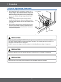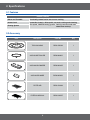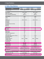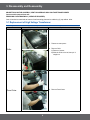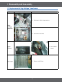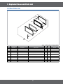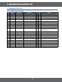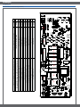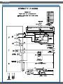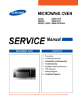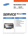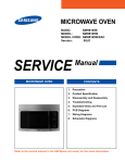
1
BASIC:
MMV1163
MODEL:
SMH9151B
MODEL CODE: SMH9151B/XAA
1. Precaution
2. Product Specification
3. Disassembly and Reassembly
4. Troubleshooting
5. Exploded Views and Part List
6. PCB Diagrams
7. Wiring Diagrams
8. Schematic Diagrams
• Contents
1. Precaution. . . . . . . . . . . . . . . . . . . . . . . . . . . . . . . . . . . . . . . . . . . . . . . . . . . . . . . . . . . . . . . . . . . . . . . . . . . . . . 3
1-1 Safety precautions. . . . . . . . . . . . . . . . . . . . . . . . . . . . . . . . . . . . . . . . . . . . . . . . . . . . . . . . . . . . . . . . . . . . . 4
1-2 Special High Voltage Precautions . . . . . . . . . . . . . . . . . . . . . . . . . . . . . . . . . . . . . . . . . . . . . . . . . . . . . . . . . 5
2. Specifications . . . . . . . . . . . . . . . . . . . . . . . . . . . . . . . . . . . . . . . . . . . . . . . . . . . . . . . . . . . . . . . . . . . . . . . . . . . 6
2-1 Features. . . . . . . . . . . . . . . . . . . . . . . . . . . . . . . . . . . . . . . . . . . . . . . . . . . . . . . . . . . . . . . . . . . . . . . . . . . . . 6
2-2 Accessory. . . . . . . . . . . . . . . . . . . . . . . . . . . . . . . . . . . . . . . . . . . . . . . . . . . . . . . . . . . . . . . . . . . . . . . . . . . . 6
2-3 Table of Specifications. . . . . . . . . . . . . . . . . . . . . . . . . . . . . . . . . . . . . . . . . . . . . . . . . . . . . . . . . . . . . . . . . . 7
3. Disassembly and Reassembly. . . . . . . . . . . . . . . . . . . . . . . . . . . . . . . . . . . . . . . . . . . . . . . . . . . . . . . . . . . . . . 8
3-1 Replacement of High Voltage Transformer . . . . . . . . . . . . . . . . . . . . . . . . . . . . . . . . . . . . . . . . . . . . . . . . . . 8
3-2 Replacement of Magnetron. . . . . . . . . . . . . . . . . . . . . . . . . . . . . . . . . . . . . . . . . . . . . . . . . . . . . . . . . . . . . 10
3-3 Replacement of Door Assembly. . . . . . . . . . . . . . . . . . . . . . . . . . . . . . . . . . . . . . . . . . . . . . . . . . . . . . . . . . 11
3-4 Replacement of Fuse. . . . . . . . . . . . . . . . . . . . . . . . . . . . . . . . . . . . . . . . . . . . . . . . . . . . . . . . . . . . . . . . . . 13
3-5 Replacement of Drive Motor . . . . . . . . . . . . . . . . . . . . . . . . . . . . . . . . . . . . . . . . . . . . . . . . . . . . . . . . . . . . 13
3-6 Removal of stirrer. . . . . . . . . . . . . . . . . . . . . . . . . . . . . . . . . . . . . . . . . . . . . . . . . . . . . . . . . . . . . . . . . . . . . 14
3-7 Replacement of Control Circuit Board. . . . . . . . . . . . . . . . . . . . . . . . . . . . . . . . . . . . . . . . . . . . . . . . . . . . . 15
3-8 Replacement of Cooktop lamp. . . . . . . . . . . . . . . . . . . . . . . . . . . . . . . . . . . . . . . . . . . . . . . . . . . . . . . . . . . 16
3-9 Replacement of Oven Light. . . . . . . . . . . . . . . . . . . . . . . . . . . . . . . . . . . . . . . . . . . . . . . . . . . . . . . . . . . . . 17
4. Troubleshooting . . . . . . . . . . . . . . . . . . . . . . . . . . . . . . . . . . . . . . . . . . . . . . . . . . . . . . . . . . . . . . . . . . . . . . . . 18
4-1 Parts checking method. . . . . . . . . . . . . . . . . . . . . . . . . . . . . . . . . . . . . . . . . . . . . . . . . . . . . . . . . . . . . . . . . 18
4-2 Error Code Numbering Rule. . . . . . . . . . . . . . . . . . . . . . . . . . . . . . . . . . . . . . . . . . . . . . . . . . . . . . . . . . . . . 19
4-3 Error Code List. . . . . . . . . . . . . . . . . . . . . . . . . . . . . . . . . . . . . . . . . . . . . . . . . . . . . . . . . . . . . . . . . . . . . . . 19
4-4 Electrical Malfunction. . . . . . . . . . . . . . . . . . . . . . . . . . . . . . . . . . . . . . . . . . . . . . . . . . . . . . . . . . . . . . . . . . 21
5. Exploded Views and Parts List . . . . . . . . . . . . . . . . . . . . . . . . . . . . . . . . . . . . . . . . . . . . . . . . . . . . . . . . . . . . 38
5-1 Exploded Views. . . . . . . . . . . . . . . . . . . . . . . . . . . . . . . . . . . . . . . . . . . . . . . . . . . . . . . . . . . . . . . . . . . . . . 38
5-2 Main Parts List. . . . . . . . . . . . . . . . . . . . . . . . . . . . . . . . . . . . . . . . . . . . . . . . . . . . . . . . . . . . . . . . . . . . . . . 39
5-3 Door Parts List. . . . . . . . . . . . . . . . . . . . . . . . . . . . . . . . . . . . . . . . . . . . . . . . . . . . . . . . . . . . . . . . . . . . . . . 41
5-4 Control Parts List. . . . . . . . . . . . . . . . . . . . . . . . . . . . . . . . . . . . . . . . . . . . . . . . . . . . . . . . . . . . . . . . . . . . . 42
5-5 Standard Parts List. . . . . . . . . . . . . . . . . . . . . . . . . . . . . . . . . . . . . . . . . . . . . . . . . . . . . . . . . . . . . . . . . . . . 43
6. PCB Diagrams. . . . . . . . . . . . . . . . . . . . . . . . . . . . . . . . . . . . . . . . . . . . . . . . . . . . . . . . . . . . . . . . . . . . . . . . . . 44
6-1 PCB Diagrams. . . . . . . . . . . . . . . . . . . . . . . . . . . . . . . . . . . . . . . . . . . . . . . . . . . . . . . . . . . . . . . . . . . . . . . 44
6-2 PCB Diagrams. . . . . . . . . . . . . . . . . . . . . . . . . . . . . . . . . . . . . . . . . . . . . . . . . . . . . . . . . . . . . . . . . . . . . . . 45
7. Wiring Diagrams . . . . . . . . . . . . . . . . . . . . . . . . . . . . . . . . . . . . . . . . . . . . . . . . . . . . . . . . . . . . . . . . . . . . . . . . 46
7-1 Wiring Diagrams. . . . . . . . . . . . . . . . . . . . . . . . . . . . . . . . . . . . . . . . . . . . . . . . . . . . . . . . . . . . . . . . . . . . . . 46
8. Schematic Diagrams. . . . . . . . . . . . . . . . . . . . . . . . . . . . . . . . . . . . . . . . . . . . . . . . . . . . . . . . . . . . . . . . . . . . . 48
8-1 Schematic Diagrams . . . . . . . . . . . . . . . . . . . . . . . . . . . . . . . . . . . . . . . . . . . . . . . . . . . . . . . . . . . . . . . . . . 48
2
1. Precaution
3
1. Precaution
Follow these special safety precautions. Although the microwave oven is completely safe during ordinary use,
repair work can be extremely hazardous due to possible exposure to microwave radiation, as well as potentially
lethal high voltages and currents.
1-1 Safety precautions (
)
13. Design Alteration Warning: Use exact replacement
parts only, i.e.,only those that are specified in
thedrawings and parts lists of this manual. This
is especially important for the Interlock switches,
described above. Never alter or add to the
mechanical or electrical design of the MWO.
Any design changes or additions will void the
manufacturer’s warranty. Always unplug the unit’s
AC power cord from the AC power source before
attempting to remove or reinstall any component or
assembly.
14. Never defeat any of the B+ voltage interlocks. Do not
apply AC power to the unit (or any of its assemblies)
unless all solid-state heat sinks are correctly
installed.
15. Some semiconductor (“solid state”) devices
are easily damaged by static electricity. Such
components are called Electrostatically Sensitive
Devices (ESDs). Examples include integrated
circuits and field-effect transistors. Immediately
before handling any semiconductor components or
assemblies, drain the electrostatic charge from your
body by touching a known earth ground.
16. Always connect a test instrument’s ground lead to
the instrument chassis ground before connecting the
positive lead; always remove the instrument’s ground
lead last.
17. When checking the continuity of the witches or
transformer, always make sure that the power is
OFF, and one of the lead wires is disconnected.
18. Components that are critical for safety are indicated
in the circuit diagram by shading,
or
.
19. Use replacement components that have the same
ratings, especially for flame resistance and dielectric
strength specifications. A replacement part that does
not have the same safety characteristics as the
original might create shock, fire or other hazards.
NOTE : Connect the oven to a 20A. When
connecting the oven to a 15A,make sure that circuit
breaker can operate.
1.
All repairs should be done in accordance with the
procedures described in this manual. This product
complies with Federal Performance Standard 21
CFR
2. Microwave emission check should be performed to
prior to servicing if the oven is operative.
3. If the oven operates with the door open :Instruct
the user not to operate the oven and contact
the manufacturer and the center for devices and
radiological health immediately.
4. Notify the Central Service Center if the microwave
leakage exceeds 5 mW/cm2.
5. Check all grounds.
6. Do not power the MWO from a “2-prong” AC cord.
Be sure that all of the built-in protective devices are
replaced. Restore any missing protective shields.
7. When reinstalling the chassis and its assemblies,
be sure to restore all protective devices, including:
nonmetallic control knobs and compartment covers.
8. Make sure that there are no cabinet openings
through which people --particularly children--might
insert objects and contact dangerous voltages.
Examples: Lamp hole,ventilation slots.
9. Inform the manufacturer of any oven foundto have
emission in excess of 5 mW/cm2 ,Make repairs to
bring the unit into compliance at no cost to owner
and try to determine cause. Instruct owner not to use
oven until it has been brought into compliance.
CENTRAL SERVICE CENTER
10. Service technicians should remove their watches
while repairing an MWO.
11. To avoid any possible radiation hazard,replace parts
in accordance with the wiring diagram. Also, use
only the exact replacements for the following parts:
Primary and secondary interlock switches, interlock
monitor switch.
12. If the fuse is blown by the Interlock Monitor Switch:
Replace all of the following at the same time:
Primary, door sensing switch and power relay, as
well as the Interlock Monitor Switch. The correct
adjustment of these switches is described elsewhere
in this manual. Make sure that the fuse has the
correct rating for the particular model being repaired.
4
1. Precaution
1-2 Special High Voltage Precautions
1.
2.
3.
High Voltage Warning Do not attempt to measure any of
the high voltages --this includes the filament voltage of the
magnetron. High voltage is present during any cook cycle.
Before touching any components or wiring, always unplug
the oven and discharge the high voltage capacitor (See
Figure 1-1)
The high-voltage capacitor remains charged about 30
seconds after disconnection. Short the negative terminal
of the high-voltage capacitor to to the oven chassis. (Use a
screwdriver.)
High voltage is maintained within specified limits by closetolerance, safety-related components and adjustments. If
the high voltage exceeds the specified limits, check each
of the special components.
H . V . Capacitor
H . V . Diode
Short
PRECAUTION
There exists HIGH VOLTAGE ELECTRICITY with high current capabilities in the circuits of the HIGH
VOLTAGE TRANSFORMER secondary and filament terminals. It is extremely dangerous to work on or
near these circuits with the oven energized.
DO NOT measure the voltage in the high voltage circuit including filament voltage of magnetron.
PRECAUTION
Servicemen should remove their watches whenever working close to or replacing the magnetron.
PRECAUTION
Never touch any circuit wiring with your hand nor with uninsulated tool during operation.
5
2. Specifications
2-1 Features
Product Features
• Stirrer and Turntable
Continually rotates food to ensure even cooking.
• Instant Cook
Instant On Controls - Allow quick, one touch cooking and reheating.
• Venting System
Two speed, 300CFM venting system - Q
uickly removes smokr and
steam from cook top
2-2 Accessory
Item
Description
Code No.
Q’ty
TRAY-COOKING
DE63-00536A
1
ASSY-GUIDE ROLLER
DE92-90495C
1
ASSY-HOOD DAMPER
DE92-90242D
1
ASSY-HARD WARE
DE92-90505G
1
FILTER-AIR
DE63-00196A
1
FILTER-CHARCOAL
DE63-00367E
1
6
2. Specifications
2-3 Table of Specifications
Items
Cavity Size (cu.ft.)
Power
Power Source
Output Power (Watts)
Power Consumption (Watts/Amp)
Characteristics
Control Method
Display
Sensor
Cooking Timer
Power Level
Auto Defrost
Auto Reheat
One Touch Instant Cook Pads
Soften/Melt
More/Less
Cooking Stages
Add 30 sec
One Minute
Clock
Kitchen Timer
Weight Option
Reminder End Signal On/Off
Child Safety Lock
Clock System Option (12 hrs / 24 hrs)
Demonstration Mode
Numeric Pads
Turntable Distribution
Turntable On/Off
End Signal Sound
Vent Fan CFM
Vent Orientation
Vent Fan Control
Cooktop Lighting
Cabinet Colour
Cavity Interior
Cabinet Dimensions W x H x D (inches)
Net Weight (lb)
Shipping Properties
Shipping Dimensions W x H x D (inches)
Loading Q’ty (sets / 40ft)
Shipping Weight (lb)
Basic Model
New Model
MMV1163
SMH9151B
1.6
1.6
120 V / 60 Hz
1000
1580/13.5
120 V / 60 Hz
1000
1580/13.5
Touch
LED
No
99 min. 99 sec.
10
Yes
Yes
Yes
Yes
Yes
2
Yes
No
Yes
Yes
Oz
No
Yes
12 hrs
No
0-9
Stirrer + Turntable
No
Yes
220
Horizontal
Hi/Lo/Off
Hi/Lo/Off
STSS/Black/White
Epoxy
29 7/8 x 16 1/2 x 15 1/16
STSS: 45.9 lbs / Plastic: 44.6
lbs
Touch
LED
No
99 min. 99 sec.
10
Yes
Yes
Yes
Yes
Yes
2
No
Yes
Yes
Yes
Oz
No
Yes
12 hrs
No
0-9
Stirrer + Turntable
No
Yes
220
Vertical
Hi/Lo/Off
Hi/Lo/Off
STSS/Black/White/Silver
Epoxy
29 7/8 x 16 1/2 x 15 1/16
33 3/8 x 19 15/16 x 19 13/32
330 (Jumbo)
STSS: 53.4 lbs / Plastic: 52.1
lbs
7
STSS: 45.9 lbs / Plastic: 44.5 lbs
33 3/8 x 19 15/16 x 19 13/32
330 (Jumbo)
STSS: 53.4 lbs / Plastic: 52.0 lbs
3. Disassembly and Reassembly
MAGNETRON, MOTOR ASSEMBLY, VENT BLOWER AND HIGH VOLTAGE TRANSFORMER
Oven must be removed from wall.
REMOVING OVEN FROM WALL (2 PEOPLE REQUIRED)
Oven is hooked on metal tabs at bottom of wall mounting plate and to cabinet by (3) top cabinet bolts.
3-1 Replacement of High Voltage Transformer
Parts
Explaination Photo
Explaination
1.
Disconnect oven power.
Grille
2.
Remove Grille.
1) Remove 2 screws
2) Slide the Grille to the left, then pull it
straght out.
Panel Outer
3.
Remove Panel Outer.
8
3. Disassembly and Reassembly
3-1 Replacement of High Voltage Transformer
Parts
Explaination Photo
Explaination
4.
Discharge the High voltage capacitor.
5.
Disconnect all the leads.
High
voltage
capacitor
Base
Bottom
HV Trans
6.
7.
9
Take out the HV Trans.
Remove Base
bottom.
3. Disassembly and Reassembly
3-2 Replacement of Magnetron
Parts
Explaination Photo
Explaination
Remove the magnetron including the shield
case, permanent magnet, choke coils and
capacitors (all of which are contained in one
assembly).
1. Disconnect all lead wires from the
magnetron.
Magnetron
2.
3.
Remove nuts (4) securing the magnetron
to the wave guide.
Take out the magnetron very carefully.
NOTE1: W
hen removing the magnetron, make sure that it antenna does not hit any adjacentparts, or it may be
damaged.
NOTE2: W
hen replacing the magnetron, be sure to remount the magnetron gasket in the correct position and make
sure the gasket is in good condition.
PRECAUTION
During replacement, be certain R.F. anode gasket is in place around anode stub.
PERFORM MICROWAVE LEAKAGE TEST
10
3. Disassembly and Reassembly
3-3 Replacement of Door Assembly
Parts
Disassembly Photo
Explaination
Removal of
Door Assembly
Removal of
Door C
Removal of Key
Door & Spring
11
1.
Insert flat screwdriver into the gap between Door
“A” and Door “C” to remove Door “C”. Be careful
when handling Door “C” because it is fragile.Then
remove the door assembly.
2.
Insert flat screwdriver into the gap between Door
“A” and Door “C” to remove Door “C”.
• Becareful when handling Door “C” because it is
fragile.
3.
Detach the spring and key door from Door.
3. Disassembly and Reassembly
3-3 Replacement of Door Assembly
Removal of
Handle
Removal of
Door “E”
PRECAUTION
PERFORM MICROWAVE LEAKAGE TEST
12
4.
Remove 2 screws, then handle is detached from
Door “A”.
5.
Following the procedure as shown in the figure,
insert and bend a thin metal plate between Door
“E” and Door “A” until you hear the ‘tick’ sound.
• Insertion depth of the thin metal plate should be
0.5mm or less.
3. Disassembly and Reassembly
3-4 Replacement of Fuse
Parts
Explaination Photo
Explaination
The fuse is located on the noise filter.
1. Disconnect power and remove grille.
2. Replace the fuse.
3. When 20A fuse blows out by the operation
of interlock monitor switch failure, replace
the primary interlock switch, secondary
interlock switch, door sensing switch,
interlock monitor switch and power relay.
4. When the above four switches operate
properly, check if any other part such as the
control circuit board, blower motor or high
voltage transformer is defective.
Fuse
3-5 Replacement of Drive Motor
Parts
Explaination Photo
Explaination
1.
2.
Drive
Motor
3.
4.
5.
13
Disconnect power and remove bottom plate
screws(5).
Remove bottom plate and disconnect the
turntable motor drive.
Remove turntable motor screws(1) and pull
the turntable motor out.
When replacing the drive motor, be sure to
remount it in the correct position with the
coupler.
Connect all the leads to the drive motor.
3. Disassembly and Reassembly
3-6 Removal of stirrer
Parts
Explaination Photo
Explaination
The stirrer is motor driver and located on the
upper side of the cavity. The oven uses a top
feed wave guide.
The stirrer is located in the wave guide and
the motor is located on the wave guide.
Stirrer
14
1.
Disconnect power and open the door.
2.
Remove the clip and turn the stirrer cover
left.
3.
Remove stirrer cover and the stirrer will
come with it.
3. Disassembly and Reassembly
3-7 Replacement of Control Circuit Board
Parts
Explaination Photo
Explaination
Removal of
Control Box
Assembly
1.
Disconnect power and remove grille.
2.
Be sure to ground any static electric charge in
your body and never touch the control circuit.
3.
Remove a screw securing the control box
assembly.
4.
Disconnect the connectors from the control
circuit board.
1.
Pull the lever end of the plastic fastener and
remove the Flexible Printed Circuit(FPC) of
membrane panel.
Remove screws (4) securing the control circuit
board.
Lift up the control circuit board from the Ass’y
control box.
When reconnecting the FPC connector, make
sure that the holes on the connector are
properly engaged with the hooks on the Plastic
Fastener.
2.
Removal of
P.C.B Assembly
3.
4.
15
3. Disassembly and Reassembly
3-8 Replacement of Cooktop lamp
When replacing the night light, make sure that you are wearing gloves to avoid injury from the heat of the bulb.
Parts
Explaination Photo
Explaination
Cooktop Lamp
16
1.
Unplug the oven or turn off the power
at the main power.
2.
Remove the bulb cover, and mounting
screws.
3.
Replace the bulb with a 40 watt
appliance bulb.
4.
Replace the bulb cover and mounting
screws.
5.
Turn the power back on at the main
power supply.
3. Disassembly and Reassembly
3-9 Replacement of Oven Light
Parts
Explaination Photo
Oven Light
17
Explaination
1.
Remove the Grille
2.
Remove the COVER LAMP by push
the hook and put up the lever.
3.
Replace the bulb with a 40 watt
appliance bulb.
4. Troubleshooting
4-1 Parts checking method
Parts
Photo
Good
No Good
Fuse
0.1 ~ 1 Ω
100 MΩ exceed
T.C.O
0.1 ~ 1 Ω
100 MΩ exceed
H.V Trans
1~9Ω
100 MΩ exceed
Convection
100 ~ 990 Ω
100 MΩ exceed
Fan Motor
10 ~ 99 Ω
100 MΩ exceed
Grill Heater
10 ~ 99 Ω
100 MΩ exceed
18
4. Troubleshooting
4-2 Error Code Numbering Rule
1.
2.
3.
4.
ERROR CODE NUMBERING RULE is applied to a microwave oven and an oven.(CMO, OTR, Grill, Convection,
Commercial etc.)
All sensors and devices have their own number. ex) Gas Sensor = 1, Temp. Sensor = 2, ...
Of each device, No.1 and No.2 refer to “Open Error” (not sensed) and “Short Error”, respectively.
This numbering rule has been applied to models to have been developed since January, 1, 2005. (But, GE or
Customize model are excluded.)
DEVICE
ERROR CASE
0- Others
1- Open
1- Gas Sensor
2- Short
2- Temp. Sensor
•
3- Weight Sensor
•
4- Easy/PH Sensor
•
5- EEPROM
•
•
4-3 Error Code List
•
Gas Sensor
Error
Code
E-11
Gas Sensor Error
Case (E-1X)
Open
E-12
Short
E-13
T1 Max Time Error
E-14
Dry Up / No Load
Solution
Check Sensor part ,connection of sensor housing and PCB’s
connector.
Page
21 Page
22 Page
23 Page
Insert food and restart.
Temp Sensor
Error
Code
E-21
E-22
E-23
E-24
E-25
E-26
Temp. Sensor Error Case (E-2X)
Open
Short
T1 Max Time Error (Preheating not
completed)
Over temperature error
In case abnormal temperature is
sensed at Micro Cook
In case the temperature is not over
the fixed AD in first 3 minutes after
cooking by heater starts.
Solution
Check sensor part and connection of sensor
housing and PCB’s connector.
Page
21 Page
22 Page
30 Page
Check heater.
33 Page
Cool down set and restart.
33 Page
Check sensor and heater.
30 Page
Eeprom Error
Error Code
E-51
E-53
E-54
EEPROM Error Case (E-5X)
Open (Sense Failure)
Read/Write Error
Zero not to be set
Solution
Replace EEPROM and restart.
19
Page
28 Page
4. Troubleshooting
Weight Sensor
Error
Code
E-31
E-32
Gas Sensor Error Case (E-1X)
Solution
E-35
Open (When value of HEX is above “FF” for 5 seconds)
Short
In case the initial value of HEX is under “14” for 30
seconds while a weight sensor in operation.
In case the initial value of K calculated by a weight
sensor is above and under “±28” as value of HEX.
In case the value of A is “-” as a weight sensor calculates.
E-36
In case the door opens during sensor cooking.
E-33
E-34
Page
21 Page
22 Page
Check Sensor.
25 Page
Cancel the present mode and
restart from the begining.
26 Page
Easy/Ph Sensor
Error
Code
Easy/PH Sensor Error Case (E4)
E-41
Open
E-42
Short
E-43
T1 Max Time Error
E-44
E-45
E-46
Dry Up
Cooling Error (3minutes)
Primary Open Error(3minutes)
E-47
The door opens during cooking
Solution
Page
21 Page
22 Page
Check Sensor.
Insert food and restart.
Remove moisture from sensor and restart.
Check Sensor.
Cancel the present mode and restart from the
begining.
23 Page
23 Page
26 Page
21 Page
26 Page
Humidity Sensor
Error Code
E-61
E-62
E-63
Humidity Sensor Error Case (E-6X)
Open
Short
T1 Max Time Error
Solution
Check Sensor.
Page
21 Page
22 Page
23 Page
Others
Error
Code
-SEE-02
E-03
E-04
E-05
E-06
Others (E-0X, Letter)
Key Short Error (10 seconds)
Cooking Time Setting Over Error (MWO)
Cooking Time Setting Over Error (Grill)
Cooking Time Setting Over Error
(Convection)
Cooking Time Setting Over Error
(Combination)
It fails to sense that the swing heater has
stopped for 20 seconds during cooking.
Solution
Page
Turn off set and restart.
24 Page
Check each mode’s setting time.
30 Page
Check Swing heater’s motor and connector.
34 Page
20
4. Troubleshooting
4-4 Electrical Malfunction
4-4-1 E-11, E-21, E-27, E-29, E-2B, E-31, E-32, E-41, E-46, E-61
Sensor Open Error (E-11, E-21, E-27, E-29, E-2B, E-31, E-32, E-41, E-46, E-61)
YES
Connect the sensor.
Is the sensor disconnected?
NO
Connect the
wire properly.
NO
Is the sensor wire
connected properly?
: Check if the sensor housing
is inserted into the connector
of the main PCB.
sensor
: Check if the sensor wire is damaged, if the
housing is loose and if the sensor and the
wire are properly connected.
YES
housing
S/W Error
Does the voltage change
as the humidity, temperature
and weight change?
NO
NO
After Power -> On, does
the symptom continue?
The sensor is out of order.
YES
Replace the PCB.
Replace the sensor.
Perform the operation again and check if it
is working properly.
21
connector
: Check if the voltage of the GND and sensor
changes using a digital multi-meter
by forcefully changing the humidity, temperature
and weight.
4. Troubleshooting
4-4-2 E-12, E-22, E-28, E-32, E2A, E-2C ,E-42, E-2C, E-42 or E-62
Sensor Short Error (E-12, E-22, E-28, E-32, E2A, E-2C, E-42, or E-62)
: Check if both terminals of the
sensor are slightly shorted.
Remove the shorted part
of the temperature sensor.
YES
Is the sensor shorted?
sensor
NO
Remove any foreign
Substance from the
shorted part.
YES
Is the sensor terminal part
of the PCB shorted?
NO
S/W Error
YES
Does the voltage change
as the humidity, temperature
and weight cha
NO
NO
After Power > On, does
the symptom continue?
The sensor is out of order.
YES
Replace the PCB.
Replace the sensor.
Perform the operation again and
check if it is working properly.
22
: Check if the sensor and related
parts such as the connector or
soldering parts are slightly shorted.
sensor
terminal
: Check if the voltage of the GND and
sensor changes using a digital multi-meter
by forcefully changing the humidity,
temperature and weight.
connector
4. Troubleshooting
4-4-3 E-13, E-14, E-43, E-44, E-63
Sensor Max Time Error (E-13, E-14, E-43, E-44, E-63)
Insert food
and heat it again.
YES
Does it heat up without
placing food into it?
: Since heating without placing food into
the oven may damage the product, take care.
NO
Place food with
moisture into it and
heat it again.
YES
Does it heat with completely
dried food?
: Since heating completely dried food
may burn the food, take care.
NO
Remove the an
foreign substance
or obstacle.
YES
Is any foreign substance
on the sensor or is something acting as an
obstacle in front of the sensor?
NO
The sensor is out of order.
Replace the sensor.
Perform the operation again and check if it
is working properly.
23
: If the sensor is contaminated by a foreign
substance, it may fail to detect the humidity.
4. Troubleshooting
4-4-4 -SE-
Key Short Error (- SE -)
YES
Is the key not recognized
at all?
NO
YES
Is the key recognized
intermittently?
NO
Is a specific key
not recognized?
YES
NO
The membrane
is defective.
S/W Error
Replace the
Control Panel.
NO
After Power > On,
does the symptom continue?
YES
Replace the PCB.
Perform the operation again and check if it
is working properly.
membrane
Connector
24
4. Troubleshooting
4-4-5 E-33, E-34 or E-35
Weight Sensor Error (E-33, E-34 or E-35)
Has the turntable
been placed over the roller
properly?
NO
Place the turntable over
the roller properly.
Remove the foreign
substance.
YES
YES
Is the weight sensor
contaminated by any foreign
substance?
NO
Place the food
in the center.
YES
Does the roller turn
and press against the
weight sensor?
NO
The sensor is out of order.
Replace the sensor.
Perform the operation again and check if it
is working properly.
25
: Check if the turntable turns abnormally
because food is placed on one side
only, or if it turns irregularly,
or if it is slanted and the
weight sensor is not pressed.
4. Troubleshooting
4-4-6 E-36 or E-47
Door Open Error(PH-Sensor, Weight Sensor), (E-36 or E-47)
Close the door.
YES
Was the door open during
the operation?
NO
Check the Door S/W
and the housing.
NO
Is the door sensing part normal?
YES
S/W Error
NO
After Power > On,
does the symptom continue?
YES
Replace the PCB.
Perform the operation again and check if it
is working properly.
26
: Check the housing connected to
the door S/W and PCB and if it is
opened or shorted intermittently.
4. Troubleshooting
4-4-7 E-45
Cooling Error (E-45)
Remove any moisture
of the sensor.
: To remove moisture from the sensor,
open the door for 5 minutes.
YES
Is the sensor wet?
sensor
NO
Check the sensor
terminal and housing.
YES
Is the sensor voltage over 3V?
: Check if the GND and sensor terminal
is maintained over 3V continuously during
the initial cooking course using a multimeter.
NO
Replace
the sensor.
Does the same symptom
continue after replacing
the sensor?
NO
YES
S/W Error
NO
After Power > On,
does the symptom continue?
YES
Replace the PCB.
Perform the operation again and check if it
is working properly.
27
sensor
terminal
4. Troubleshooting
4-4-8 E-51, E-53 or E-54
EEPROM Error (E-51, E-53, or E-54)
Insert and solder
an EEPROM
NO
EEPROM이
삽입been
되었는가?
Has the EEPROM
inserted?
: An R4LCO40 or 24LCO4 EEPROM
is to be used. Check if a proper EEPROM
has been installed.
YES
Replace the
EEPROM and repair
the short circuit.
YES
IsEEPROM
the EEPROM
terminal
opened or
단자가
Open/Short
is there
a short-circuit?
되었는가?
NO
EEPROM Defect
Replace the EEPROM
YES
Does it work properly?
NO
S/W Error
S/W 오동작
NO
After Power > On,
does the symptom continue?
YES
Replace the PCB.
Perform the operation again and check if it
is working properly.
28
MICOM
EEPROM
4. Troubleshooting
4-4-11 E-0b, E-2b, E-2C, 0t
Cooling Fan Motor Sensor Error
(E-0b, E-2b, E-2C, Ot)
Is the temperature
sensor of the PCB open?
YES
An “E-2b” error
occurred.
NO
Insert the
temperature sensor.
Was there a shortcircuit in the temperature
sensor of the PCB?
YES
An “E-2C, 0t” error occurred.
NO
Repair the short circuit.
Is the temperature
of the PCB over 90°C?
YES
An “E-0b” error
occurred.
NO
NO
Is the Cooling Motor
rotating?
S/W Error
YES
Check the Motor
drive part.
The temperature
sensor is out of order.
NO
Replace the
temperature sensor.
After Power > On,
does the symptom
continue?
YES
Replace the PCB.
Perform the operation again and check if it
is working properly.
29
4. Troubleshooting
4-4-12 E-23, E-26
Preheating Error (E-08, E-23, E-26)
: Check the voltages of
both heater terminals.
Check the heater
related drive part.
NO
Does the heater work?
YES
Replace the
heater.
YES
Is the heater temperature
very low?
NO
Reconnect the
temperature
sensor properly.
NO
Heater
terminal
: After operating the heater for more then
10 minutes check if the heater temperature
remains low.
Is the temperature sensor
connected properly?
YES
Replace the
heater.
YES
Is the resistance
between the heater terminals
more then a few MΩ?
: A normal heater’s resistance is a few Ω.
A short circuit increases the resistance
to a few MΩ.
NO
S/W Error
Heater
terminal
NO
After Power > On,
does the symptom continue?
YES
Replace the PCB.
Perform the operation again and check if it
is working properly.
30
4. Troubleshooting
4-4-13 E-02, E-03, E-04 or E-05
Cooling Time Over Selection Error
(E-02, E-03, E-04, or E-05)
Is this
happening during
the MW operation?
YES
NO
Is it
happening during
the Grill operation?
NO
YES
NO
Over Time is
set?
Over Time is
set?
Is it
happening during
the Convection
operation?
YES
An “E-02” error
occurred.
NO
NO
YES
Over Time is
set?
Is it
happening during
the Combination
operation?
NO
YES
YES
An “E-03” error
occurred.
Over Time is
set?
YES
An “E-04” error
occurred.
NO
YES
Press the Cancel
key to cancel the
current state.
An “E-05” error
occurred.
Press the Cancel
key to cancel the
current state.
Repeat the operation and check
if it is working properly.
: Since the max. time may differ
depending on the model,
refer to the IB
For example,
Ex)
31
MW Mode
Max Time
Grill
60 mins
Convection
45 mins
Conbination
45 mins
4. Troubleshooting
4-4-14 E-24
“E-09,
E-24,
E-0A” 가 표시된다
Oven
Temperature
Error
An “E-09” error
occurred.
YES
(E-24)
Is the oven internal temperature
maintained over 320 degrees?
NO
An “E-24, E-0A” error
occurred.
YES
Has the oven internal temperature
reached over 350 degrees?
NO
Reconnect the
temperature
sensor properly.
NO
Is the temperature
NO sensor
connectivity normal?
YES
Off
TurnOven을
the oven
off하고
and let
it 충분히
cool sufficiently.
식힌다.
Check
and repair
히터
the구동부를
heater
점검
수리한다
drive
part if
necessary.
NO
Is the Heater
connectivity normal?
YES
S/W Error
NO
After Power > On,
does the symptom
continue?
YES
Replace the PCB.
Perform the operation again and check
if it is working properly
sensor
housing
32
4. Troubleshooting
4-4-15 E-25
Initial Temperature Error
(at MW mode), (E-25)
Is the oven in MW mode?
NO
YES
An “E-25” error
occurred.
Press the Cancel key.
YES
Is the internal temperature
over 200 degrees?
NO
Press the Cancel
key to cancel the
current state.
Connect it
properly
and try again.
NO
Is the sensor connectivity
normal?
YES
S/W Error
NO
After Power > On,
does the symptom continue?
YES
Replace the PCB.
Perform the operation again and check if it
is working properly.
33
4. Troubleshooting
4-4-16 E-06
Swing Heater Detection Error (E-06)
Is the oven in
Bake Toast mode?
NO
YES
After waiting for 20 seconds,
check if the micro-switch has
been detected.
NO
Has the switch heater
operated for 20 seconds?
YES
Has the micro-switch
been detected?
NO
The micro-switch is
defective Replace it.
YES
micro
switch
Is connectivity housing
of the micro-switch normal?
YES
S/W Error
NO
After Power > On,
does the symptom continue?
YES
Replace the PCB.
Perform the operation again and
check if it is working properly.
34
NO
Connect the
micro-switch properly.
4. Troubleshooting
4-4-17 If oven malfunction
*Inspection method
Oven does not operate.
NO
Is Fuse OK?
Is Primary interlock
switch normal?
NO
YES
YES
Is the magnetron
temperature switch normal?
NO
Is Power Relay normal?
NO
Replace switch
NO
Power supply circuit check point
YES
Is SMPS power supply
cirduit normal?
NO
Do check power supply
circuit
NO
NO
Do check
Relay control circuit
NO
YES
Is the IC01 output of
PCB normal?
Relay control circuit check point
Is high voltage dioed
normal?
YES
Checking high
voltagecircuts
Is high voltage dioed
normal?
NO
YES
Is high voltage
capacitor normal?
NO
YES
Is magnetron normal?
35
NO
4. Troubleshooting
4-4-18 If button malfunction
Buttons of the control panel do not work.
Are button pressed
in the correct order?
NO
Is the connector of the
control panel normal?
Refer to User Manual
Tact type
YES
*Inspection method
NO
YES
Replace PCB.
Menbrane type
36
4. Troubleshooting
4-4-19 If food is not heated even though an oven works
Food is not heated even though an oven works.
Is the latch switch
operating normally?
NO
*Inspection method
Method to control latch switch
YES
Checking high voltage circuits
37
5. Exploded Views and Parts List
5-1 Exploded Views
P007
P012
P013
M086
P032
M024
P014
M061
P039
T017
M015
M001
M036
U003
T001
M030
P030
M206
P426
M040
M068
M039
M041
M042
M098
M029
P001
H018 M202
M023
T036
M034
T037
M036
M111
U003
B006
M051
C081
U007
M049
P109
M017
B002
M087
M155
U001
W002
U005
U012
B001
B001
B013
B018
M038
P123 M131
P122
M131
P090
U008 M060
P087
P088
P091
P089
38
M048
5. Exploded Views and Parts List
5-2 Main Parts List
(SNA : SERVICE NOT AVAILABLE)
No.
Code No.
Description
Specification
Q’ty
SA/
SNA
Remark
B001
3405-001034
SWITCH-MICRO
125/250VAC,16A,200GF,SPST-N
2
SA
-
B002
3405-001033
SWITCH-MICRO
125/250VAC 16A,200GF,SPSTNC
1
SA
-
B006
DE66-00168A
LATCH-BODY
MODULAR-2,PP,-,-,-,-,-
1
SA
-
B013
DE66-90106B
LEVER-SWITCH LOWER
PP,T1.4,-,-,2.0g,OTR
1
SA
-
B018
DE96-00414A
ASSY BODY LATCH
RVM-1625BJ,-
1
SA
-
C081
DE66-20095B
BUTTON-LOCK
-,-,OTR5,-,-,TB53)
1
SA
COVER STIRRER
H018
DE31-90051A
BLADE-FAN
P.P,T,D130,-,-,-,-
1
SA
-
M001
DE64-02083B
PANEL-OUTER
MODULAR3,SECC,T0.4,-,-,-,BLA
1
SA
-
M015
DE96-00218C
ASSY POWER CORD
UL,USA,125V/15A,1000MM,2
1
SA
-
M017
DE96-00400A
ASSY NOISE FILTER
SN-UF12A,250V20A,OTR7,
1
SA
CAVITY UPPER
M023
DE31-10155T
MOTOR-FAN
SMF-437UA3,120V60HZ,2780RPM
1
SA
-
M024
DE31-00028L
MOTOR VENTILATION
-,SMV-280UAL,-,-,-,-,2
1
SA
-
M029
DE47-20007A
THERMOSTAT
PW-2N(160/60)187Z,250V7.5A,16
1
SA
MGT
M030
DE47-20196A
THERMOSTAT
NT-101NA(8XV)P,100/0,250V/7.5
1
SA
CAVITY UPPER
M034
DE67-00236A
COUPLER
MMV1163,SPS,-,-,-,MODULAR-3
1
SA
-
M036
4713-001013
LAMP-INCANDESCENT
130V,-,40W,ORG,E17/20,
1
SA
DUCT UPPER
M036
4713-001013
LAMP-INCANDESCENT
130V,-,40W,ORG,E17/20,
1
SA
-
M038
DE26-00143C
TRANS H.V
SHV-U1750C,120V,60HZ,2380V/3.5
1
SNA
-
M039
2501-001011
C-OIL
910nF,2100V,BK,54x35x75mm,20mm
1
SA
-
M040
DE61-00115A
BRACKET-HVC
SMH7175,SECC,T0.6,-,-,-,-
1
SA
-
M041
DE91-70063D
ASSY-HVD
HV03-12,MWO-GE,RED
1
SA
-
M042
DE59-00002A
DIODE-H.V
2CL4512H,450mA, 13KV,MWO ALL,
1
SA
-
M048
DE61-01048A
BASE-PLATE
MODULAR3,SECC,T0.5,-,-,-,-
1
SNA
-
M049
DE31-10172B
MOTOR SYNCHRONOUS
SM16FBY36P1AW3,OTR,-,F
1
SA
T/T
M051
DE63-00532A
COVER-MGT
MODULAR3,PP,-,-,-,-,-,-,-
1
SA
-
M060
DE92-90505G
ASSY-HARD WARE
MMV1153,-,-,-
1
SA
-
M061
DE63-00367E
FILTER-CHARCOAL
MODULAR-2,AL,CARBON,T9,W
1
SA
FILLER SET
M068
DE64-02139D
GRILLE
SMH9151,PC,-,-,-,-,SILVER,1.5
1
SA
-
M086
DE63-00541A
COVER-LAMP
MD3,SECC,0.4,-,-,-,-,-,-
1
SA
DUCT UPPER
M087
DE63-00534A
COVER-STIRRER
MODULAR3,PP,-,-,-,-,-,-,-
1
SA
-
M098
DE61-00164A
HOLDER-WIRE
OTR8,PP(JI350),-,-,-,NTR,-
1
SA
CAVITY UPPER
M111
DE61-30129A
SUPPORTER-PCB
-,DASS-T9N,-,-,-,-,-
3
SA
N/FILTER +
C/UPPER
M131
DE66-00123A
WIRE-SADDLE
JE620/610BF/WF,-,-,-,-
1
SA
ASSY BASE-PLATE
M131
DE66-00123A
WIRE-SADDLE
JE620/610BF/WF,-,-,-,-
1
SA
-
M155
DE94-01926A
ASSY BASE PLATE
MODULAR 3,SECC,T0.5,-
1
SNA
-
M202
DE81-01614A
SPRING-BLADE
D1,0/D9.8,X7XCOILS=5,-,-,-,
1
SNA
-
M206
DE96-00269A
ASSY-HVC
SMH7175,0.91UF HVC
1
SA
-
P001
DE94-01917A
ASSY STIRRER
MMV1163,ALP T0.5
1
SA
-
P007
DE70-00561A
PLATE-MOUNTING
GE 1.6 NEW APPEARANCE,GI,
1
SA
-
P012
DE92-90242D
ASSY-HOOD DAMPER
JVM-1870,JVM250BL OTR4,
1
SA
-
P013
DE71-60051B
COVER-DAMPER
JVM-1870,-,0.22,68,248.4,-,
1
SNA
-
P014
DE72-40022A
DAMPER-MAIN
-,SECC,-,W28,L650,OTR4,-,T0.
1
SNA
-
P030
DE59-50002A
CAPACITOR-MOTOR
SH-M 10UF,220V10UF,-,DMB
1
SA
39
CAVITY UPPER
5. Exploded Views and Parts List
5-2 Main Parts List (Continued)
(SNA : SERVICE NOT AVAILABLE)
No.
Code No.
Description
P032
DE92-90508A
ASSY-HOLDER NUT
P039
DE67-00232A
P087
DE60-10111A
P088
P089
Specification
Q’ty
SA/
SNA
Remark
OTR6,-,-,-,-,-
2
SA
DUCT-UPPER
MODULAR3,PP,T1.5,-,-,-,-
1
SA
-
SCREW-LAG
-,-,-,-,MSWR,W1/4X50,-,-,-,-
1
SNA
-
DE60-20022A
BOLT-TOGGLE
MSWR,W3/16X75,-,-,-,-,-,-,-
2
SNA
-
DE60-20066A
BOLT-FLAT
UNF1/4,L110,MSWR10,-,-,OTR6,-,
2
SNA
-
P090
DE60-30022A
NUT-TOGGLE
SBC1,ZPC2,WHT,-,-,-,-,-,-
2
SNA
-
P091
DE63-10011A
GROMMET
-,MS,-,-,-,DACB-16,-,-,-
1
SNA
-
P109
DE63-00533B
COVER-MOTOR
MODULAR3,PP TB53
1
SA
-
P122
DE47-20059A
THERMOSTAT
PW-2N(8XV),125V15A,V,120/0,23
1
SA
-
P123
DE47-20034A
THERMOSTAT
40/70,M5,-,-,-,-,-,-
1
SA
-
P426
DE63-00549A
COVER FRONT
;MODULAR3,SECC,T0.5,-,-,-,-,-
1
SA
-
T001
DE63-00536A
TRAY-COOKING
MODULAR3,GLASS,T5.0,-,-,-,C
1
SA
-
T017
DE92-90495C
ASSY GUIDE ROLLER
MD3 1.5/1.7,SPS,TEFLON
1
SA
-
T036
DE31-00055A
BLADE-STIRRER
MODULAR3,ALP1050,-,-,-,T0.
1
SNA
-
PANEL OUTER
T037
DE61-01061A
HOLDER-STIRRER
MD3,SPS,-,-,-,-,-
1
SNA
-
U001
DE97-00679J
ASSY BASE BOTTOM
MD3 SMH8165B,SECC,T0.4,
1
SNA
-
U003
DE47-00006A
HOLDER-LAMP
250V,75W,250X187 2POLE,OTR
1
SA
-
U003
DE47-00006A
HOLDER-LAMP
250V,75W,250X187 2POLE,OTR
1
SA
-
U005
DE67-40063A
GLASS-COOKTOP LAMP
-,GLASS,T3.2,W59,L159
1
SA
-
U007
DE61-00857E
BASE-BOTTOM
MAYTAG1.5/1.6,SECC,T0.4,-,-,
1
SA
-
U008
DE63-00196A
FILTER-AIR
SMH7175,AL-MESH,T2.0,W150,L34
1
SA
-
U012
DE63-00100B
COVER-COOKTOP LAMP
OTR-9,SECC,T0.4,-,-,-
1
SA
-
W002
DE96-00740A
ASSY WIRE HARNESS-A
MMV1163DA,120V/60HZ,
1
SA
-
40
5. Exploded Views and Parts List
5-3 Door Parts List
D006
D005
D004
D011
D007
D024
D002
D020
D049
(SNA : SERVICE NOT AVAILABLE)
No.
Code No.
Description
Specification
Q’ty
SA/SNA
Remark
D002
DE64-01949F
DOOR-A
SMH9151S,PC,-,-,-,-,SILVER,NO
1
SNA
D004
DE94-01469G
ASSY DOOR-E
MAYTAG1.5/1.6,-,COATING
1
SA
ASSY DOOR
-
D005
DE01-00091A
FILM-DOOR
-,POLYESTER,-,L458,T0.015,W198
1
SA
-
D006
DE64-02056A
DOOR-C
SMH8165,PP,-,-,-,-,-,ARCADIA
1
SA
-
D007
DE61-00048A
SPRING-KEY
BLUING,HSWR,PI1.95,D8.75,L43
1
SA
-
D011
DE64-01308A
DOOR-KEY
MODULAR-2,POM,-,-,-,-,BLK,-
1
SA
-
D020
DE94-01814A
ASSY HANDLE
SMH8165BG/XAA,-,BLK,ARCADIA
1
SA
ASSY DOOR
D024
DE64-02053A
SCREEN-DOOR(B)
SMH8165,TEMPERED GLASS,T3
1
SA
-
D049
DE94-01811L
ASSY DOOR
SMH9151S,PC,SILVER,NO LOGO
1
SA
-
41
5. Exploded Views and Parts List
5-4 Control Parts List
C082
C003
C001
P157
C005
C009
C004
(SNA : SERVICE NOT AVAILABLE)
No.
C001
Code No.
DE94-01806K
Description
ASSY CONTROL PANEL
Specification
SMH9151S,SILVER,PC,1.
Q’ty
SA/SNA
1
SNA
C003
RAS-SM6L-01
ASSY PCB PARTS
SMH9151,SMPS,120V60HZ
1
SNA
C004
DE34-00304F
SWITCH MEMBRANE
SMH9151B/XAA,MD3,-,-,PET
1
SA
Remark
ASSY CTRL BOX
ASSY CTRL BOX
ASSY CTRL PANEL
C005
DE64-01950D
CONTROL-PANEL
SMH9151S,PC,-,-,-,-,SILVER
1
SNA
ASSY CTRL PANEL
C009
DE64-00766A
WINDOW-DISPLAY
SMH7175,SAN,T2.0,SMOG
1
SA
ASSY CTRL PANEL
C082
DE94-01807N
ASSY CONTROL BOX
SMH9151S,120V60HZ,SILVE
1
SA
-
P157
DE94-01810B
ASSY BRACKET C/PANEL
SMH8165,-,-,MD3-LED
1
SNA
42
ASSY CTRL BOX
5. Exploded Views and Parts List
5-5 Standard Parts List
(S.N.A : SERVICE NOT AVAILABLE)
Level
Code No.
Description
Specification
Q’ty
SA/
SNA
Remark
1-1
6002-000643
SCREW-TAPPING
TH,+,2S,M4,L10,ZPC(YEL),SW
2
SNA
C/FRONT + B/PLATE,C/UPPER + C/FRONT
1-1
6002-001173
SCREW-TAPPING
FH,+,2S,M4,L12,ZPC(BLK),MS
5
SNA
GRILLE,P/OUTER SIDE
1-1
6003-001568
SCREW-TAPTITE
FH,TORX,-,B-TITE,M4,L14,NI
2
SNA
BODY LATCH
1-1
6006-001170
SCREW-ASSY TAPP
WS,TH,+,M4,L10,ZPC(YEL)
2
SA
N/FILTER GROUND,P/CORD GROUND
1-1
DE60-10045A
SCREW-TAP PH
-,-,FEFZY,-,PH,M3,-,L6,-,-
2
SA
MGT + TCO
1-1
DE60-10051A
SCREW-TAP PH
-,-,MSWR,-,PH,M4,-,L6,-,-
1
SA
T/T MOTOR
1-1
DE60-10062A
SCREW-TAP TH
-,-,FEFZB,-,TH,M4,-,L12,-,-
3
SNA
C/FRONT + C/BOX,P/OUTER + D/UPPER
1-1
DE60-10067A
SCREW-TAP TH
-,-,FEFZB,2-SLOT,TH,M4,-,L8
8
SA
BASE BOTTOM,P/OUTER SIDE
1-1
DE60-10080A
SCREW-WASHER
-,-,-,-,M5,L12,-,2S,-,-
6
SA
HVT,MGT
1-1
DE60-10082I
SCREW-A
-,-,-,-,2S-4X10,FEFZY,-,-,-,-
18
SA
C/BACK + B/PLATE,C/BACK + M/PLATE,C/BACK
+ P/OUTER,C/BACK + V/T MOTOR,C/UPPER +
BKT MGT,C/UPPER + BK
1-1
DE92-90508A
ASSY-HOLDER NUT
OTR6,-,-,-,-,-
2
SA
PANEL OUTER
1-2
DE60-10111A
SCREW-LAG
-,-,-,-,MSWR,W1/4X50,-,-,-,-
1
SNA
-
1-2
DE60-20022A
BOLT-TOGGLE
MSWR,W3/16X75,-,-,-,-,-,-,-
2
SNA
-
1-2
DE60-20066A
BOLT-FLAT
UNF1/4,L110,MSWR10,-,-,OTR6,-,
2
SNA
-
1-2
DE60-30022A
NUT-TOGGLE
SBC1,ZPC2,WHT,-,-,-,-,-,-
2
SNA
-
1-2
6002-000630
SCREW-TAPPING
PH,+,2S,M3,L8,ZPC(YEL),SWR
4
SNA
ASSY-PCB
1-2
DE60-10062A
SCREW-TAP TH
-,-,FEFZB,-,TH,M4,-,L12,-,-
2
SNA
HANDLE
1-2
6002-001004
SCREW-TAPPING
TH,+,2,M4,L30,ZPC(YEL),SWR
2
SA
-
1-2
DE60-10045A
SCREW-TAP PH
-,-,FEFZY,-,PH,M3,-,L6,-,-
2
SA
-
1-2
6006-001170
SCREW-ASSY TAPP
WS,TH,+,M4,L10,ZPC(YEL)
1
SA
ASSY DIODE
1-2
DE60-10067A
SCREW-TAP TH
-,-,FEFZB,2-SLOT,TH,M4,-,L8
1
SA
-
43
6. PCB Diagrams
6-1 PCB Diagrams
(This Document can not be used without Samsung’s authorization)
⑬
⑦ ⑥ ⑧ ⑤ ① ⑨ ②
④
⑩
③
Function and Rule
⑪
Part Name
⑫
Main Relay
Inrush Relay
Power High Relay
Power Low Relay
Bright Relay
Vent High Relay
Vent Low Relay
Vent Mid Relay
Night Relay
Inrush Connector
Power & Relay Connector
Parts
No.
Number
RY01
RY02
RY03
RY04
RY05
RY06
RY07
RY08
RY09
CN01
CN02
Door switch Sensing Connector
Membrane switch Connector
1
2
3
4
5
6
7
8
9
10
11
CN03
CN04
Fan, Lamp, T/T Control
Inrush Electric Current Decrease
MW Power Control(High Power)
MW Power Control(Low Power)
Turn on High Light
Turn on High Ventilation
Turn on Low Ventilation
Turn on Mid Ventilation
Turn on Low Light
A Terminal for Inrush Circuit
A Terminal for Connecting with Power supply & Relay
Contact(Load Control)
A Terminal for Connecting with Door Switch
A Terminal for Connecting with Membrane Switch
12
13
44
6. PCB Diagrams
6-2 PCB Diagrams
(This Document can not be used without Samsung’s authorization)
CN03
1) DOOR SWITCH1 (RY_12V)
2) GND
3) DOOR SWITCH1 (12V)
4) GND
CN04
1) KEY OUTPUT1
2) KEY OUTPUT2
3) KEY OUTPUT3
4) KEY OUTPUT4
5) KEY OUTPUT5
6) KEY OUTPUT6
7) KEY OUTPUT7
8) KEY OUTPUT8
9) KEY INPUT1
10) KEY INPUT2
11) KEY INPUT3
12) KEY INPUT4
13) KEY INPUT5
14) ENCODER COMMON (ENCODER S/W MODEL)
CN02
1) MAIN RELAY
2) NO PIN
3) BRIGHT / NIGHT RELAY
4) NO PIN
5) VENT LOW RELAY
6) NO PIN
7) VENT HIGH RELAY
8) NO PIN
9) VENT MID RELAY
CN01
1) POWER (LIVE)
2) NO PIN
3) INRUSH CIRCUIT (MODEL OPTION)
RY04
1) POWER RELAY CONTACT1(HVT POWER1)
AC POWER NEUTAL (AC98V ~ 144V)
2) POWER RELAY CONTACT2(HVT POWER3)
RY03
1) POWER RELAY CONTACT1(HVT POWER1)
AC POWER NEUTAL (AC98V ~ 144V)
2) POWER RELAY CONTACT2(HVT POWER2)
45
7. Wiring Diagrams
7-1 Wiring Diagrams
(This Document can not be used without Samsung’s authorization)
46
7. Wiring Diagrams
7-1 Wiring Diagrams
(This Document can not be used without Samsung’s authorization)
47
8. Schematic Diagrams
8-1 Schematic Diagrams
(This Document can not be used without Samsung’s authorization)
LIVE
R101
51K
PC101
PC817
1N4007
1N4007
D101
D102
1N4007
1N4007
D103
D104
INTERRUPT
+5V
R16
R02
4.7K
OR01
2K
TR14
KRC246M
4.7K
PTC1
390M
ZNR1
10D471
+5V
R01
10K
4
3
INT
L101
1mH
2K
2
1
5
R105
510K
IC101
LNK564P
C103
1nF
D105
1N4007
BP
S8
D
S1
S7
FB
S2
7
8
4
3
C104
POWER SUPPLY
SOURCE
C101 C102
4.7uF 4.7uF
R104
SOURCE
RY-INRUSH
RELAY CONTROL
TR02
KRC246M
R12
RY-POWER-H
6
10
ST1
BCK-1605_EE1616
1
2
4
5
D106
1N4007
100nF
3
2
1
4
5
R14
470
R107
3K
R106
47K
+5V
CN03
SMW250-05V_WHT
LIVE
R102
51K
1
2
INRUSH
RY02
G5T-1A-12VDC
D02
MM4148
POWER-HIGH
TR03
4.7K
RY-POWER-L
RY-POW-CON
D107
UF4007
C105
1uF
+12V
+12V
C107
470uF
R05
10K
C01
10uF
R03
2K
+5V
2K
R15
C10
100nF
IC02
78L05
IC03
7033P
C05
100nF
+5V
+5V
C108
47uF
+5V
RESET
RESET
R18
2K
C16
100nF
DOOR
DOOR
R04
4.7K
TR12
KRC246M
TCO
+5V
C03
100nF
C04
100nF
LED-S4
LED-S3
LED-S2
LED-S1
9
10
11
12
13
e
d
c
b
a
DISPLAY
LED-S1
LED-S5
MICOM
12
LED-S2
IC01
TPM87PH47U
VDD
11
C09
22nF
40
VAref
10
LED-S3
LED-S7
LED-S6
6
7
8
uc_lc
g
f
DOV
LED-S8
1G
LED-S4
1
2G
LED-S5
2
3G
9
3
4G
8
LED-D1
LED-D2
LED-D3
4
TEST
LED-S7
LED-D1
6
LED-D2
LED-S8
3
LED-D3
5
1
LED-D4
LED-D5
+5V
X
X
X
X
X
X
OPTION OPTION OPTION OPTION OPTION
4
3
1
2
5
X
X
MODEL
RVM1435
X
5
0
START/
PAUSE
VENT
FAN
SURFACE
LIGHT
D16
1N4148M
O
D14
1N4148M
4
BEVERAGE
POWER
TIME
LEVEL COOK1&2
9
D15
1N4148M
RVM1625
D13
1N4148M
3
8
5
13
KRA226-AT
TR15
KRA226-AT
TR16
KRA226-AT
TR17
KRA226-AT
TR18
LED-S6
RESET
44
KEYIN_1
LED-D4
KEYIN_2
LED-D5
39
KEYIN_3
43
38
KEYIN_4
KEY-OUT
2
37
KEYIN_5
42
34
36
41
BZ
24
35
D12
1N4148M
2
7
TIMER
CLEAR/ AUTO
ADD
DEFROST POPCORN 30SEC
OFF
DELAY
START
TR19
KRA226-AT
7
14
X-IN
X-OUT
DOOR
32
PDO
RY-MAIN
30
NC3
RY-INRUSH
NC4
RY-POWER-H
28
NC2
27
NC1
25
4
21
19
RY-NIGHT
23
RY-VENT-H
TIME
DEFROST
CLOCK
REHEAT
6
1
D11
1N4148M
CN04
12516HS-14
RY-POWER-L
C15
31
1nF
20
C14
RY-VENT-M
1nF
RY-VENT-L
C13
22
1nF
33
C12
MODEL OPTION
VSS
R11
47K
18
LED-S2
17
RESET
29
C07
R10
47K
26
16
15
INT
20pF
XTL1
8MHz
R09
47K
RY-BRIGHT
20pF
R08
47K
RY-POW-CON
C08
R07
47K
1nF
TCO
KEY-INPUT
KEYIN_1
C11
D17
1N4148M
D18
1N4148M
OPTION
1
OPTION
2
OPTION
3
4
OPTION
OPTION
5
48
RY03
DU12D1-1P
KRC246M
R13
4.7K
C06
100nF
RY-MAIN
RY-BRIGHT
KEYIN_2
KEYIN_3
KEYIN_4
KEYIN_5
1nF
LED-S3
DSP1
CSE-4046G-10
KEY-OUT
MM4148
D03
TR04
KRC246M
+5V
TR10
KRA226-AT
TR01
KRC246M
TR05
KRC246M
BZ
BUZZER
TR13
KRC246M
LED-S8
DU12D1-1P
MM4148
D04
TR11
KRC246M
C02
10uF
D01
MM4148
D05
MM4148
RY-NIGHT
+12V
R06
1K
RY-V
BZ01
CBE2220BA
LED-S7
POWER-LOW
RY04
MAIN
RY01
G5T-1A-12VDC
BRIGHT
RY05
G5T-1A-12VDC
NIGHT
RY09
G5T-1A-12VDC
TR06
KRC246M
RY-VENT-H
RY-VENT-M
RY-VENT-L
LED-S6
PTC2
390M
NEUTRAL
D10
1T4
D06
MM4148
TR07
KRC246M
TR08
KRC246M
TR09
KRC246M
LED-S5
1
3
1
3
5
7
RY06
G5T-1A-12VDC
D07
D09
MM4148
D08
MM4148
VENT(HIGH) MM4148
RY07
G5T-1A-12VDC
RY08
G5T-1A-12VDC
VENT(MID)
VENT(LOW)
RY-V
+12V
LED-S4
LIVE
9
LIVE
NEUTRAL
CN01
SMW250-03AV_RED
CN02
SMW250-09AV_RED
GSPN (Global Service Partner Network)
Contry
Web Site
North America
service.samsungportal.com
Latin America
latin.samsungportal.com
CIS
cis.samsungportal.com
Europe
europe.samsungportal.com
China
china.samsungportal.com
Asia
asia.samsungportal.com
Mideast & Africa
mea.samsungportal.com
© Samsung Electronics Co., Ltd. January. 2009
Printed in Korea
Code No. : DE68-05276A