1
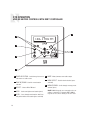
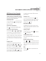
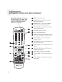
ST2 Smart Tuner
Dual AM/FM Tuner
Installation Manual
IMPORTANT SAFEGUARDS
11.Grounding or Polarization - Precaution should be taken so that the
grounding or polarization means of an appliance is not defeated.
12.Power Cord Protection - Power supply cords should be routed so that
they are not likely to be walked on or pinched by items placed upon or
against them, paying particular attention to cords at plugs, receptacles,
and the point where they exit from the appliance.
WARNING: TO REDUCE THE RISK OF FIRE OR ELECTRIC SHOCK,
DO NOT EXPOSE THIS APPLIANCE TO RAIN OR MOISTURE.
CAUTION: TO REDUCE THE RISK OF ELECTRIC SHOCK, DO NOT
REMOVE COVER. NO USER - SERVICEABLE PARTS INSIDE.
REFER SERVICING TO QUALIFIED SERVICE PERSONNEL.
14.Non-use Periods - The power cord of the appliance should be
unplugged from the outlet when left unused for a long period of time.
15.Object and Liquid Entry - Care should be taken so that objects do not
fall and liquids are not spilled into the enclosure through the openings.
The lightning flash with arrowhead symbol, within an equilateral
triangle, is intended to alert the user to the presence of uninsulated
“dangerous voltage” within the product’s enclosure that may be of
sufficient magnitude to constitute a risk of electric shock to persons.
16.Damage Requiring Service - The appliance should be serviced by qualified service personnel when:
The exclamation point within an equilateral triangle is intended to
alert the user to the presence of important operating and maintenance (servicing) instructions in the literature accompanying the
appliance.
B. Objects have fallen, liquid has been spilled into the appliance; or
If you have any questions please call Russound Inc. at
1-800-638-8055 or 603-659-5170.
E. The appliance has been dropped or the enclosure is damaged.
Safety Instructions:
1. Read Instructions - All the safety and operating instructions should be
read before the appliance is operated.
2. Retain Instructions - The safety and operating instructions should be
retained for future reference.
3. Heed Warnings - All warnings on the appliance in the operating instructions should be adhered to.
4. Follow Instructions - All operating and user instructions should be followed.
5. Water and Moisture - The appliance should not be used near water; for
example, near a bathtub, washbowl, kitchen sink, laundry tub, in a wet
basement, or near a swimming pool.
6. Carts and Stands - The appliance should be used only
with a cart or stand that is recommended by the
manufacturer. An appliance and cart combination
should be moved with care. Quick stops, excessive
force and uneven surfaces may cause the appliance
and cart combination to overturn.
7. Wall or Ceiling Mounting - The appliance should be mounted to a wall
or ceiling only as recommended by the manufacturer.
8. Ventilation - The appliance should be situated so that its location or
position does not interfere with its proper ventilation. For example, the
appliance should not be situated on a bed, sofa, rug, or similar surface
that may block the ventilation openings, or placed in a built-in installation, such as a bookcase or cabinet that may impede the flow of air
through the ventilation openings.
9. Heat - The appliance should be situated away from heat sources such
as radiators, heat registers, stoves, or other appliances (including
amplifiers) that produce heat.
10.Power Sources - The appliance should be connected to a power supply
only of the type described in the operating instructions or as marked on
the appliance.
2
13.Cleaning - The appliance should be cleaned only as recommended by
the manufacturer.
A. The power supply cord or the plug has been damaged; or
C. The appliance has been exposed to rain; or
D.The appliance does not appear to operate normally; or
17.Servicing - The user should not attempt to service the appliance beyond
that described in the operating instructions. All other servicing should
be referred to qualified service personnel.
Precautions:
1. Power – WARNING: BEFORE TURNING ON THE POWER FOR THE
FIRST TIME, READ THE FOLLOWING SECTION CAREFULLY.
2. Do Not Touch The ST2 With Wet Hands – Do not handle the ST2 or
power cord when your hands are wet or damp. If water or any other liquid enters the ST2 cabinet, unplug the unit from power immediately and
take the ST2 to a qualified service person for inspection.
3. Location of ST2 – Place the ST2 in a well-ventilated location. Take special care to provide plenty of ventilation on all sides of the ST2 especially when it is placed in an audio rack. If ventilation is blocked, the ST2
may overheat and malfunction. Do not expose the ST2 to direct sun
light or heating units as the ST2 internal components temperature may
rise and shorten the life of the components. Avoid damp and dusty
places.
4. Care – From time to time you should wipe off the front and side panels
of the cabinet with a soft cloth. Do not use rough material, thinners,
alcohol or other chemical solvents or cloths since this may damage the
finish or remove the panel lettering.
This device complies with Part 15B of the FCC Rules.
Operation is subject to the following two conditions: (1) This
device may not cause harmful interference, and (2) this device
must accept any interference received, including interference
that may cause undesired operation.
Changes or modifications not expressly approved by
Russound could void the user’s authority to operate this equipment.
TABLE OF CONTENTS
Product Introduction..........................................................................................................4-5
Component Guide
ST2 Front Panel ..................................................................................................................6
ST2 Rear Panel ...................................................................................................................7
ST2-RC Remote Control .......................................................................................................8
ST2 Setup and Connections
Basic Connections...............................................................................................................9
CAV6.6 Connections .........................................................................................................10
CA Series and ST2-KP Connections ....................................................................................11
Antenna Connections ....................................................................................................12-13
ST2 Operation
Front Panel Controls ..........................................................................................................14
ST2-RC Remote Control .....................................................................................................15
ST2-KP Keypad Control......................................................................................................16
UNO-S2 Keypad Controls with RNET Controller ...............................................................17-18
SRC2 Remote Control with RNET Controller....................................................................19-20
ST2 Tuner Programming
ST2 Chassis Setup Menu ...................................................................................................21
Source Number .........................................................................................................21
Update Firmware .......................................................................................................21
Factory Initialization ...................................................................................................22
System Info...............................................................................................................23
Tuner Setup Menu for AM/FM.............................................................................................23
Memory Name...........................................................................................................23
Bank Name ...............................................................................................................23
Region ......................................................................................................................24
Backup and Restore .........................................................................................................24
Programming RNET Controller............................................................................................25
Technical Specifications.................................................................................................26
Warranty .........................................................................................................................27
3
INTRODUCTION
DESCRIPTION
Thank you for choosing the Russound ST2 Smart
Tuner. Whether you are adding radio to an existing system, expanding a CA Series system or
taking advantage of a CAV6.6 or CAM6.6 controller’s robust RNET® communication link, the
ST2 Tuner is designed to meet your needs.
The ST2 Tuner gives you two radios in one. The
two AM/FM tuner modules share one set of controls and display on the front of the unit, but
each runs independently. This arrangement
allows two different broadcasts at the same time
in a multi-room audio distribution system.
In addition to the traditional AM/FM broadcast
tuner function, the ST2 Tuner can store up to 72
favorites, or memory presets. These are stored
in groups of six called banks. There are six
banks for each tuner. Each preset and each bank
can be given a custom name of your choice.
The ST2 Tuner can be controlled from the front
panel or by the dedicated ST2-KP tuner keypad.
It can also be controlled by the ST2-RC IR remote
aimed at the tuner’s front panel IR receiver. The
ST2-RC IR codes can be learned into any IR
learning remote control for easy system integration. It can also be controlled by IR signals
received through the IR connections on the rear
panel from IR repeating system commonly used
in distributed audio systems.
If the ST2 Tuner is part of an RNET-enabled system such as the CAV6.6-S2 system, the tuner
can be controlled through an UNO-S2 keypad.
The ST2 Tuner also has an RS-232 port to support fully bi-directional integration into wholehouse control systems such as Crestron® and
AMX®.
4
FEATURES
• Dual AM/FM Tuners
• Compact single rack unit chassis
(Rack mount ears included)
• Six banks of six memory presets each per
tuner for storing AM/FM station settings
(72 total presets)
• Two Favorite presets per tuner with ST2-RC
• Stereo or mono mode
• Local or distant mode
• Dedicated IR remote control
• Individual IR direct inputs for each tuner
• Front panel IR receiver
• Supports optional ST2-KP tuner keypads
• RNET connections send tuner frequency and
control information to UNO keypad display
• RS-232 control and programming. User
settings can be backed up and restored.
INSTALLATION APPLICATIONS
RNET-enabled System
When the ST2 Tuner is used with an RNETenabled device such as the CAV6.6 and is connected to it through the Link In or Link Out port,
the tuner will be controlled by the CAV6.6
through the UNO-S2 keypad. Through RNET,
tuner information such as Tuner 1 or 2, station
frequency, preset names and AM/FM band is displayed on UNO-S2 keypads. An additional RNET
device can be connected to an existing ST2 by
using the Link Out of the first unit into the Link In
of the second unit.
Before using the ST2 tuner with a Russound
RNET controller, you must assign source
numbers to Tuner 1 and 2 in the ST2 Setup
Menu AND complete the controller’s Source
Setup procedure to identify the tuner as a
“Peripheral“ command type device.
INTRODUCTION
IR-controlled System
CA Series The ST2 Tuner can be controlled by infrared
commands received through the two IR connections on the rear panel. The ST2 contains two
individual tuners, which makes it act as two
sources in the CA system. There are two source
audio outputs and two IR connections - one for
each tuner in the ST2. You will need at least one
IR link cable (Russound P/N 09-0508) for these
connections. There are two unique IR code sets
for Tuner 1 and Tuner 2, which allow each to be
controlled independently from either IR connection. These codes can be learned from the ST2RC remote control into the CAS-RC remote control. If you are using an IR-controlled system from
another manufacturer, installation should be similar. The ST2 IR codes may be learned into many
other manufacturers’ remote controls that have
learning capability for unified control over the A-V
equipment.
BOX CONTENTS
The ST2 Tuner comes with the parts needed to
setup and operate the component. These
include:
•
•
•
•
•
•
•
ST2 Tuner (two AM/FM modules)
ST2-RC remote control
12VDC power supply
AM loop antenna (2)
FM antenna (2)
RCA audio cable (2)
Rack mount ears
If any of these parts are missing, please call
Russound at 800-638-8055 ext. 501 for
assistance.
Note: Optional ST2-KP keypads can be used to
provide control for the ST2 Tuner and are
designed to be used with IR-controlled systems.
RS-232 Controlled System
The ST2 Tuner can be controlled using the RNET
protocol provided via the RS-232 port on the
rear panel. It can also be controlled by any
RS-232-enabled control system (e.g., Crestron,
AMX). Information on RS-232 operation is available to dealers in the Document Center on the
Russound web site, www.russound.com.
5
COMPONENT GUIDE
ST2 FRONT PANEL
1
4
2
3
5
6
7
8
9
13
6
10
12
11
1
MAIN POWER SWITCH - Turns power on and off
2
POWER ON/OFF LED - Indicates power on or off
3
REMOVABLE COVER LENS - Covers the selection buttons on the tuner
4
BANK SELECT BUTTON - Selects bank 1-6
5
MEMORY SELECT BUTTONS - Sets and selects memory presets 1-6 for each bank
6
IR RECEIVER - Receives IR signal from remote control
7
LCD PANEL - 12-character backlit display shows station, custom names, etc.
8
TUNER 1/TUNER 2 - Backlit tuner selection indicator
9
TNR SEL - Selects Tuner 1 or Tuner 2, and accesses tuner setup menus
10
BAND - Selects AM or FM band, enters menu selections when programming
11
ST/MONO - Selects stereo or mono mode for AM/FM, and Distant/Local reception
12
MEM PRESET UP/DOWN - Selects memory presets starting with last preset, and toggles through
menu features
13
TUNE UP/DOWN - Manually selects radio stations, toggles through menu settings
COMPONENT GUIDE
ST2 REAR PANEL
1
2
NEWMARKET, NH U.S.A.
3
ST2
Smart Tuner
RS-232
LINK
KEYPAD PORTS
5
FM COAX
6
LOOP
ANTENNA
IR
7
TUNER 2
AUDIO OUTPUT
L
R
FM COAX
8
9
10
LOOP
ANTENNA
IR
11
TUNER 1
AUDIO OUTPUT
L
R
12
Serial#
12VDC 1.25A
MADE IN KOREA
INTERFACE
IN
4
OUT
TUNER 2
TUNER 1
1
RNET LINK IN/LINK OUT - Links to other Russound components that are RNET compatible, displays frequency and other information on the UNO keypads
2
RS-232 INTERFACE - The RS-232 Interface allows the tuner to be controlled by PC or other devices
that have an RS-232 Interface. The RS-232 Interface also allows for firmware updates and programming (DB9 Cable)
3
KEYPAD PORTS - RJ-45 Keypad ports for ST2-KP tuner keypads in dedicated, non-RNET systems (Do not connect UNO keypads to these ports)
4
FM COAX - FM Antenna threaded F-connection (75 ohms)
5
LOOP ANTENNA - AM antenna connection (300 ohms)
6
IR INPUT - IR control input (direct IR control per tuner)
7
AUDIO OUTPUT - Line level audio signal outputs (RCA Cable)
8
FM COAX - FM Antenna threaded F-connection (75 ohms)
9
LOOP ANTENNA - AM antenna connection (300 ohms)
10
IR INPUT - IR control input (direct IR control per tuner)
11
AUDIO OUTPUT - Line level audio signal outputs (RCA Cable)
12
POWER SUPPLY - 12VDC external power supply connection
7
COMPONENT GUIDE
ST2-RC REMOTE CONTROL
1
1
POWER - Puts the tuner in/out of standby mode
2
TUNER CONTROL - Select Tuner 1 or
Tuner 2 and all subsequent button presses affect
that tuner
2
3
TUNER 1
4
BANK SELECT - Used for direct bank selection
5
TUNE SELECT - Used for direct station selec-
TUNER 2
(numeric input 1-6)
3
15
14
1
2
3
4
5
6
7
8
9
MEM
0
13
AM/FM
6
5
7
6
TUN
7
E
SEEK
12
LOC/
DX
LOCAL/DISTANCE - Optimizes station reception
10
OK - Confirms direct entries
11
STEREO/MONO - Selects stereo or mono
broadcast
9
8
TUNE UP/DOWN - Scrolls through station
numbers
13
10
SEEK UP/DOWN - Seeks the next tuned station
9
12
TUNE
FAV 1/FAV 2 - Sets/Selects Favorite 1 or 2
preset selection on ST2 tuner
up/down
8
ST/
MONO
11
8
FAV 2
OK
TUNE UP/DOWN - Incrementally scrolls through
station numbers
BANK
TUNE
FAV 1
SEEK
tion (numeric input)
4
TUNE
MEM
NUMERIC INPUT - Number buttons for direct
selection of station, bank, preset
PWR
MEM UP/DOWN - Scrolls through preset stations within selected bank
14
AM/FM - Selects AM or FM band
15
MEM SELECT - Used for direct memory select
(numeric input 1-6)
ST2 SETUP AND CONNECTIONS
BASIC CONNECTIONS
Power
To power the tuner, connect the 12VDC external
power supply by inserting the power supply jack
into the power supply connection on the tuner’s
rear panel.
ST2-KP RJ-45 Connection Wiring
Audio Output
Connect one end of a dual RCA audio cable to
the Tuner 1 Audio Output connection. Keep proper channel identity. Attach the other end of the
RCA cables to the source input of the audio control system. Repeat the same procedure for the
Tuner 2 Audio Output.
IR Connections
The ST2 Tuner can be controlled by infrared
commands received through the two IR connections on the rear panel. The ST2 Tuner component contains two tuners, which must be set up
as two sources. There are two IR connections one for each tuner in the ST2. You will need two
IR link cables (Russound P/N 09-0508) for these
connections. There is a unique IR code set each
for Tuner 1 and Tuner 2, which allow each to be
controlled independently. These codes can be
learned from the ST2-RC remote into learningcapable remotes and keypads. If you are using
an IR-controlled system from another manufacturer, installation should be similar. The ST2 IR
codes may be learned into many other manufacturers’ remote controls that have learning capability for unified control over the A-V equipment.
RNET Connection
To link the ST2 to an RNET-compatible device,
use a CAT-5 passthrough patch cable with similar wiring terminations at each end. Connect one
end of the cable to the RNET Link In of the ST2
tuner, and connect the other end of the patch
cable to the RNET Link Out connection on the
RNET-compatible device.
ST2-KP Keypad to ST2 Connection
(Non-RNET System)
The ST2-KP connects to the ST2 tuner with
CAT-5 cable, using an RJ-45 (T568A) jack on the
tuner connection end of the cable. Be sure to
use the keypad ports for the ST2-KP and NOT
the RNET link ports. The ST2 tuner provides
connections for up to two ST2-KP keypads. An
SA-ZX3 Keypad Splitter can be used to add additional keypads.
Note: ST2-KP keypads are designed for use
with IR-controlled systems (non-RNET systems).
When the ST2 Tuner is a component of an RNET
system such as CAV6.6, the RNET-system
UNO-S2 keypads are used.
Rack Mount Installation
The ST2 can be mounted in a standard component rack using the rack ears provided. Line up
the rack ear’s two rows of screw holes with the
three screw holes on the side of the tuner. Use
the screws provided to secure the rack ears
onto the unit on both sides. The ST2 tuner
should not be installed above a high heat-producing component such as a power amplifier.
9
ST2 SETUP AND CONNECTIONS
CAV6.6 CONNECTIONS
UNO-S2
keypads
NEWMARKET, NH U.S.A.
LINK
ST2
Smart Tuner
RS-232
IN
KEYPAD PORTS
FM COAX
LOOP
ANTENNA
IR
TUNER 2
AUDIO OUTPUT
L
R
FM COAX
ST2 Tuner
LOOP
ANTENNA
IR
TUNER 1
AUDIO OUTPUT
L
R
Serial#
12VDC 1.5A
MADE IN KOREA
INTERFACE
AM loop antenna
FM antenna
FM antenna
AM loop antenna
OUT
CAV6.6
RCA Cable
Source Connections with CAV6.6 Controller/Amplifier
The diagram depicts a typical setup using the ST2 Tuner with a CAV6.6 amplifier. Each tuner in the
ST2 unit must be connected as a separate source for audio inputs. UNO-S2 keypads are connected
to the CAV6.6 keypad ports, NOT the ports on the ST2 Tuner.
10
ST2 SETUP AND CONNECTIONS
CA SERIES AND ST2-KP CONNECTIONS
RCA Cable
IR Link Cable
Pos (+)
Source
Neg (–)
KPL
ST2-KP
LINK
ST2
Smart Tuner
RS-232
INTERFACE
IN
KEYPAD PORTS
FM COAX
LOOP
ANTENNA
IR
TUNER 2
AUDIO OUTPUT
L
R
FM COAX
LOOP
ANTENNA
IR
TUNER 1
AUDIO OUTPUT
L
R
Serial#
12VDC 1.25A
MADE IN KOREA
NEWMARKET, NH U.S.A.
OUT
IR Link Cable
ST2 Tuner
RCA Cable
RCA Cable
CAS44
Source Connections with CA Series Controller/Amplifier
The diagram depicts a typical setup using the ST2 Tuner with a CAS44 controller amplifier. Each
tuner in the ST2 unit must be connected as a separate source for audio inputs.
CAT-5 Cable
ST2-KP Connections to ST2 Tuner (Non-RNET Systems)
The diagram depicts a standard ST2-KP keypad connection to the keypad port on the back of the
ST2. The keypad uses a 110 punchdown connection and an RJ-45 T568A connection to the tuner.
11
ST2 SETUP AND CONNECTIONS
ANTENNA CONNECTIONS
AM Antenna
External Antenna
Connect the included loop antenna for AM reception to the back panel, attaching the GND
(ground) and AM ends to the appropriate connections for each tuner.
It is recommended to use an external outdoor or
attic-mounted long wire antenna for best performance for AM/FM reception. For AM, use a
75-ohm to 300-ohm balun at the AM connection
on the tuner, and attach the 75-ohm coax cable
to the balun. For FM, attach the desired length
of 75-ohm coax cable directly to the FM connection on the tuner.
FM Antenna
Attach the included FM antenna to the FM COAX
connection on the back panel by pushing the
F-type quick-connect termination of the antenna
onto the FM connection.
Long wire antenna
75-ohm coax
Outdoor antenna
LINK
ST2
Smart Tuner
RS-232
INTERFACE
IN
KEYPAD PORTS
FM COAX
LOOP
ANTENNA
IR
OUT
TUNER 2
AUDIO OUTPUT
L
R
FM COAX
LOOP
ANTENNA
IR
TUNER 1
AUDIO OUTPUT
L
R
Serial#
12VDC 1.25A
MADE IN KOREA
NEWMARKET, NH U.S.A.
300 ohm
to 75 ohm
balun
FM antenna
75-ohm coax
AM loop antenna
ST2 Tuner
Connecting an Indoor and Outdoor Antenna
The diagram above depicts a typical setup using the ST2 Tuner with the included FM antenna and AM
loop antenna. Also shown are two outdoor antenna options (not included). (Diagram not to scale)
12
ST2 SETUP AND CONNECTIONS
ANTENNA CONNECTIONS
Antenna
Lead In Wire
Electric
Service
Equipment
Grounding
Conductors
Ground
Clamps
Power Service
Grounding
Electrode System
Grounding an Outdoor Antenna
If the tuner is used with an outdoor antenna, the antenna must be grounded against static charges
and voltage surges. Consult the instructions that came with the antenna or contact the antenna manufacturer for proper installation instructions. The diagram gives a general depiction of how an outdoor
antenna should be grounded. For complete guidelines on antenna grounding procedures, please consult the National Electrical Code, Section 810, ANSI/NFPA No. 70-1984.
13
ST2 OPERATION
FRONT PANEL CONTROLS
Front Panel Operation
Memory Preset programming
Turning the unit on
From the front panel, perform these steps:
To turn the unit on, push the On/Off button up on the
front panel. Pushing the On/Off button down turns the
tuner off.
1. Select a tuner using
2. Use
.
to choose from one of six banks (1-6).
Selecting the desired tuner
From the front panel, use
to toggle between
Tuner 1 and Tuner 2. A backlight shows behind the
selected label TUNER 1 (green) or TUNER 2 (amber)
to indicate the active tuner. In addition, the LCD panel
is also backlit green for Tuner 1 and amber for Tuner
2. Each time a tuner is selected the display will
refresh with the current station or preset, and all subsequent memory preset entries will be associated
with that selected tuner.
3. Select the desired band (AM/FM) using
.
4. Tune to the desired station.
5. Push the desired memory preset (M1 through M6)
button for more than 2 seconds. When the memory
preset is saved, the appropriate preset number (M1
through M6) and SAVED appears on the LCD. The
selected station setting reappears after the button is
released.
Recalling a Memory Preset
Selecting the desired band
Push
to switch between AM and FM reception.
Selecting the desired frequency
Press and release
and
for manual tuning.
Selecting Stereo or Mono Output
Press and release
to toggle between stereo and
mono mode. STEREO or MONO appears briefly on the
screen when selecting mode.
Selecting Distant or Local Reception
Press and hold
to toggle between distant and
local mode. DISTANT or LOCAL appears briefly on the
screen when selecting mode. Normal operation is in
Distant mode. In cities, antennas can pick up multipath signals when they bounce off buildings and get
doubled. The Local mode limits the noise associated
with these reflected signals.
Bank/Memory Presets
Each tuner has six banks of preset memory settings,
and each bank holds six presets for a total of 36 possible presets for each tuner (72 total presets).
Presets are associated with the tuner that is selected
at the time the preset is saved.
14
To recall a memory preset, use
to select the
desired bank, then press the desired preset button
(M1 to M6). In addition to direct selection, the memory presets can be accessed by using
and
scroll through all presets for the bank selected.
to
Backup and Restore
Once all of the tuner settings are completed, it may
be advisable to create a backup of the programmed
settings for future use. The backup will then be available in case tuner settings need to be restored. The
“RNET Backup Utility” is available through the
Document Center at www.russound.com. Also
required are a DB9 male-to-female cable and laptop
or desktop PC.
ST2 OPERATION
ST2-RC REMOTE CONTROL
ST2-RC Remote Control Operation
Selecting Stereo or Mono Output
Turning the unit on
To take the ST2 tuner out of standby mode, push
PWR
or any other button except TUNER 1 or
TUNER 2.
Selecting the desired tuner
(Note: To change the tuner that is audio-active, you
must have some other system control in place to
change the source)
TUNER 1
TUNER 2
To control a tuner, push
or
. When
pressed, these buttons will be backlit green for Tuner
1 and amber for Tuner 2. After a tuner is selected,
the next button press refreshes the display with the
current station or preset for that tuner, and all subsequent button presses and memory preset entries will
be associated with that selected tuner.
Selecting the desired band
AM/FM
Push
ST/
MONO
Press
to toggle between stereo and mono mode.
STEREO or MONO appears briefly on the screen when
selecting mode. Normal operation is in stereo mode.
On a preset, the stereo/mono setting is saved for
that preset.
Selecting Distant or Local Reception
LOC/
DX
Press
to toggle between Distant and Local
mode. DISTANT or LOCAL appears briefly on the
screen when selecting mode. Normal operation is in
Distant mode.
Recalling a Memory Preset
To recall a memory preset, select the desired tuner,
press
BANK
to select the desired bank, then press
MEM
and enter the desired preset number (1 to 6).
The memory presets can also be accessed by using
to switch between AM and FM reception.
Selecting the desired frequency
TUNE
Use
and
for manual tuning. To move quickly
through the stations, press and hold either of the
Tune buttons for more than 1.5 seconds.
TUNE
MEM
and
to scroll through all presets for the
selected bank.
MEM
Saving Favorites
The remote control stores two “favorites” (similar to
memory presets) per tuner. These are set simply by
selecting either Tuner 1 or Tuner 2, setting the
TUNE
To directly select a station, press
, and enter
the three- or four-digit station frequency (1071 for
107.1, etc.). European regions use five-digit station
frequencies.
Frequency Seek
desired frequency and pressing and holding
FAV 1
or
FAV 2
until “FAV1 (2) saved” appears on the tuner.
Stored Favorites are then recalled by pressing either
FAV 1
or
FAV 2
.
The SEEK function is performed by pressing and
releasing
to seek lower frequencies or
for
higher frequencies. SEEK tuning begins at the current
frequency, seeks upward and stops at the next tuned
station. Pushing
continues the SEEK function.
Once the highest frequency is reached, the tuner continues in SEEK mode at the lowest frequency.
15
ST2 OPERATION
ST2-KP KEYPAD CONTROL
ST2-KP Keypad Operation
1
5
Turning the keypad on/off
To activate the ST2-KP, press
. Press
to
power down the keypad display. The keypad remains
powered until the ST2 Tuner is turned off.
1
ST2-KP Keypad Display
The 5-character backlit display shows frequency and
band, plus presets. Messages scroll twice, then display the first 5 characters.
Selecting the desired tuner
To select a different tuner, press and hold
. (If the
keypad has been hardware jumper-selected to Tuner
1 or Tuner 2, it will not switch between the two
tuners.) The backlight color of the display will be
green for Tuner 1 and amber for Tuner 2. Each time
a tuner is selected the display will refresh with the
current station or preset for that tuner, and all subsequent button presses and memory preset entries will
be associated with that selected tuner.
2
Push
3
Use
to switch between AM or FM band.
3
Selecting the desired frequency
2
and
or
Selecting a Bank
To select a bank, select the desired tuner, then press
and hold
or
to select the desired bank. The
bank name will show on the display.
Recalling a Memory Preset
To recall a memory preset, press and release
to scroll through the presets for the selected
bank. (Memory presets must be stored for ST2-KP
recall)
16
3
for manual tuning. To move quickly
for more than 1.5 seconds. European frequencies show in .05 MHz increments.
4
5
Selecting the desired band
through the channels, press and hold either
4
ST2-KP Keypad-Front Panel
or
4
1
ST2 OPERATION
UNO-S2 KEYPAD CONTROL WITH RNET CONTROLLER
UNO-S2 Keypad Operation
Frequency Scan
NOTE: To control the ST2 Tuner through the
UNO-S2 keypad, the tuner must be configured
as a source using the RNET Controller programming steps.
To scan, press and hold then release
Turning the unit on
The tuner is power managed by the RNETenabled controller. If the tuner is in standby
mode, any button press of the UNO-S2 keypad
will bring the tuner out of standby mode.
tuner scans through tuned stations with a 5-second preview before moving to the next station.
To end scanning, press
On the UNO-S2 keypad, press
to select
again.
Selecting a Bank
To select a bank, press and hold
up or
Selecting the desired tuner
. The
for bank
for bank down. The bank’s name will
be temporarily displayed on the UNO-S2.
either Tuner 1 or Tuner 2 by choosing the
Recalling a Memory Preset
tuner’s preassigned source number.
Press
Selecting the desired band
ry presets for the selected bank. This procedure
Push
will step through all of the presets in the current
to toggle between AM band and FM
to scroll through the memo-
bank, then loop back to start at the first one.
band reception.
Only configured presets will be displayed.
Selecting the desired frequency
Use
and
and
for manual tuning. The fre-
Mute
quency will appear on the keypad and the active
Press
tuner. To move quickly through the stations,
put.
press and hold either
or
to mute/unmute the tuner audio out-
for more than
1.5 seconds.
Frequency Seek
A press on
will seek the next higher tune-
able station. If a tuneable station is not found,
end the SEEK function by pressing
again.
17
ST2 OPERATION
UNO-S2 KEYPAD CONTROLS WITH RNET CONTROLLER
1
6
104.1 MHz FM
5
2
4
3
1
TUNER SELECTION - Scrolls through sources to
select tuner as audio source
2
MUTE - Mutes/unmutes tuner audio output
6
BANK SELECT - Used for bank selection (press
TUNE UP/DOWN - Used for manual station
selection
3
SELECT - Selects AM or FM band
4
SEEK - Seeks next higher tuned station (press)
4
SCAN - Scans through tuned stations with 5-second preview before next station (press and hold)
18
5
and hold)
6
MEM UP/DOWN - Scrolls through memory preset
stations (press)
NOTE: UNO-S2 keypads are connected to the controller to control the ST2 through RNET. UNO-S2
keypads do not connect directly to the ST2 Tuner.
ST2 OPERATION
SRC2 REMOTE CONTROL WITH RNET CONTROLLER
SRC2 Remote Control Operation
is reached, the tuner continues SEEK mode at the
Turning the unit on
lowest frequency.
The tuner is power managed by the RNET-enabled
controller. If the tuner is in standby mode, any button
press of the SRC2 will bring the tuner out of standby
mode when used with the UNO keypad.
Frequency Scan
To scan, press and hold then release
. The
tuner scans through tuned stations with a 5-second
Selecting the tuner
To select a tuner, push
until the desired tuner
is selected, or use the numeric source inputs at the
preview before moving to the next station. To end
scanning, press
again.
bottom of the SRC2.
Bank/Memory Presets
Selecting the desired band
The AM/FM tuner has six banks of preset memory
Push
settings, and each bank holds six presets for a total
to toggle between AM/FM reception.
of 36 possible presets.
Selecting the desired frequency
Selecting a Bank
Use the Channel
and
or
and
To select a bank, press and hold
for bank up
for manual tuning. To move quickly through the staor
for bank down.
tions, press and hold the button for more than 1.5
seconds. To directly select a station, enter the threeor four-digit channel or frequency (1071 for 107.1,
etc.). European regions use five-digit station frequen-
Saving a Memory Preset
Press and hold numeric buttons (1-6) for saving memory presets.
cies.
Recalling a Memory Preset
Frequency Seek
Press
or
or
higher frequency station press
. Press
. To seek
for
rently selected bank. Only configured presets will be
displayed.
lower frequencies. Tuning begins at the current fre-
Mute
quency, seeks upward (or downward) and stops at the
Press the
next tuned station. Pushing
audio output.
or
to scroll through a loop dis-
play of all the configured memory presets for the cur-
The SEEK function is performed by pressing and
releasing the Select
and
again con-
button to mute/unmute the tuner
tinues the SEEK function. Once the highest frequency
19
ST2 OPERATION
SRC2 REMOTE CONTROL WITH RNET CONTROLLER
RUSSOUND SELECTION - “R” must be
the selected source for control of the
controller and any connected components. Select “R” before sending
SRC2 remote commands.
1
POWER - Powers off the zone
2
NUMERIC INPUT - (press) Number buttons for
direct input of frequency
2
MEMORY PRESETS - (press and hold) Number
buttons (1-6) for saving memory presets
3
TUNE UP/DOWN - Incrementally scrolls through
channels or tuned stations
1
4 OK - Confirms numeric selection
2
5
PLAY - Selects AM or FM band
6
SCAN - (press and hold) Scans through tuned stations with 5-second preview before next station
6
SEEK UP/DOWN - (press) Seeks next tuned
station up or down
7
MEM UP/DOWN - (press) Scrolls through memory
presets for selected bank
3
7
BANK UP/DOWN - (press and hold) Used for bank
selection
4
8
TUNER SELECTION - Select AM/FM Tuner by its
assigned source number
3
9
PAUSE - Mutes/unmutes tuner audio output
11
10
9
5
6
10 SEEK UP/DOWN - Seeks next tuned station up or
down
11 TUNE UP/DOWN - Incrementally scrolls through
7
8
20
tuned stations
ST2 TUNER PROGRAMMING
ST2 TUNER SETUP MENU
ST2 Tuner Setup Menus
Note: The Setup Menu procedures must be performed from the ST2 Tuner front panel.
The ST2 Tuner Setup Menus provide setup and naming procedures for the ST2 main chassis, and
each AM/FM tuner module. These procedures include source number assignments, assigning a custom name to a memory preset or a bank, choosing a region for AM/FM operation (US or Euro), factory initialization and system information.
If the ST2 is used with a non-RNET system, the ST2 can be connected and operated without any
setup programming. Follow the setup menus if custom names are desired, or for system information.
If the ST2 is used with an RNET system such as CAV6.6, the following minimum setup must be performed for the ST2 to be properly controlled by the RNET controller.
1. ST2 Chassis Setup Menu - Assign source numbers to Tuner 1 and Tuner 2.
2. RNET Controller Source Setup Menu - Configure the source numbers assigned in step 1 for Tuners
1 and 2, and assign command type PERIPHERAL.
NOTE: Once the programming procedures are completed, cycle power first to the Tuner and then to
the RNET controller (must be powered on last) to establish a connection.
ST2 Chassis Setup Menu
Source Number (Chassis)
The Source Number procedure permits Tuner 1
and Tuner 2 to be assigned the proper source
numbers to be used in an RNET system.
Note: The source number must be assigned as
PERIPHERAL in the RNET controllers.
Note: Each of the ST2 modules can be configured as source number “unassigned” if the module is used in another system (e.g., home theater) or will not be used as a source in the RNET
system.
1. Enter the Setup Menu by pressing and holding
the TNR SEL button.
2. TUNER SETUP appears. Press MEM Up/Down
until SOURCE NUM appears on the tuner.
3. Press BAND. TUNER # appears.
4. Press the Tune Up/Down buttons to select the
Tuner #.
5. Press BAND. SOURCE NUM appears.
6. Press the Tune Up/Down buttons to scroll
through the source numbers 1-6.
7. Press BAND to select the source number.
8. Repeat the process for the next tuner.
9. Press TNR SEL to exit the Source Number
menu.
Update Firmware (Chassis)
The Update Firmware procedure allows the ST2
tuner’s OS firmware to be updated. The procedure is performed using a DB9 serial cable with
one end connected to the RS-232 port on the
back of the tuner and the other connected to a
PC or laptop. If an OS firmware update is available, it can be obtained through the Document
Center at www.russound.com.
(continued)
21
ST2 TUNER PROGRAMMING
ST2 TUNER SETUP MENU
Press and Hold
TNR SEL button
TNR
SEL
ST2 Chassis Setup Procedures
TNR
SEL
TUNER
SETUP
Menu
SOURCE
NUM
Procedure
UPDATE
FIRMW
Procedure
FACTORY
INIT
Procedure
SYSTEM
INFO
Procedure
Chassis
Setup
Menu
TNR
SEL
TUNER
#
HOLD
BAND
This
Procedure
returns the
ST2 Tuner
to its
Factory
settings
After update
cycle Power
Are you sure
SOURCE
NUM
Start
Update
YES
NO
Cycle Power
Please wait
Cycle Power
Update Firmware (Chassis) (cont’d)
1. Enter the Setup Menu by pressing and holding
the TNR SEL button.
2. TUNER SETUP appears. Press MEM Up/Down
until UPDATE FIRMW appears on the tuner.
3. Press BAND to enter the UPDATE FIRMW menu.
4. “Hold BAND” appears on the tuner.
5. While pressing and holding BAND, “After
update cycle power” appears on the tuner display.
6. When “Start Update” appears on the tuner display, start the update program. “Finished” will
then appear in firmware’s update window on the PC.
7. Cycle power to the tuner.
Factory Initialization (Chassis)
The Factory Initialization procedure allows the
erasure of all programmed settings and returns
22
them to the factory default settings.
1. Enter the Setup Menu by pressing and holding
the TNR SEL button.
2. TUNER SETUP appears. Press MEM Up/Down
until FACTORY INIT appears on the tuner.
3. Press BAND to enter the FACTORY INIT menu.
4. “Are you sure” appears on the tuner. Using the
Tune Up/Down buttons, view the “Yes” and “No”
selections.
5. Press BAND to select. A “No” selection
returns to the top of the Factory Init menu. A
“Yes” begins the initialization.
6. “Please wait” appears on the tuner during the
process and “Cycle Power” appears when complete.
7. Cycle power on the ST2 tuner.
ST2 TUNER PROGRAMMING
ST2 TUNER SETUP MENU
System Info (Chassis)
1. Enter the Setup Menu by pressing and holding
the TNR SEL button.
2. TUNER SETUP appears. Press MEM Up/Down
until SYSTEM INFO appears on the tuner.
3. Press BAND.
4. Press BAND at “Build Time” to view.
5. Press MEM Up/Down to advance.
6. Press BAND at “Build Date” to view.
7. Press MEM Up/Down to advance.
8. Press BAND at “Version” to view.
9. Press TNR SEL to exit the System Info menu.
appears again.
10. Press BAND to access the Memory Name
entry screen.
11. Press Tune Up/Down to select a character
and MEM Up/Down to change a character position. Up to 12 characters can be entered one by
one. A blinking cursor indicates the placement of
the character being entered.
12. Press BAND when memory name is entered.
13. SAVE CHANGES will appear.
14. Press Tune Up/Down to select Yes or No.
15. Press BAND to save memory name. The
Memory Name menu returns to the Tuner #
prompt to name other presets, or press TNR
SEL to exit the Memory Name menu.
(END OF ST2 CHASSIS SETUP)
Bank Name (AM/FM)
The System Info menu shows the ST2 Tuner’s
manufacturing build properties.
Tuner Setup Menu for AM/FM
It is important to select the desired tuner
(Tuner 1 or Tuner 2) using the TNR SEL button BEFORE accessing the Tuner Setup
Menus.
Memory Name (AM/FM)
A memory preset must be created and saved
before it can be named. Once it is saved, the
preset’s Tuner #, Bank # and Memory # must be
entered in the following procedure.
1. Enter the Setup Menu by pressing and holding
the TNR SEL button.
2. TUNER SETUP appears. Press BAND again.
3. MEMORY NAME appears on the tuner.
4. Press BAND.
5. Bank # appears.
6. Press the Tune Up/Down buttons to select the
Bank #.
7. Press BAND to advance.
8. Press the Tune Up/Down buttons to select a
Memory #.
9. Press BAND to advance. MEMORY NAME
A custom name can be assigned to each of the
six banks of each tuner.
1. Enter the Setup Menu by pressing and holding
the TNR SEL button.
2. TUNER SETUP appears. Press BAND.
3. MEMORY NAME appears. Press MEM
Up/Down until BANK NAME appears on the tuner.
4. Press BAND.
5. Bank # appears.
6. Press BAND to advance.
7. Press the Tune Up/Down buttons to select the
Bank #.
8. Press BAND. BANK NAME appears again.
9. Press BAND to access the Bank Name entry
screen.
10. Press Tune Up/Down to select a character
and MEM Up/Down to change a character position. Up to 12 characters can be entered one by
one. A blinking cursor indicates the placement of
the character being entered.
11. Press BAND when bank name is entered.
12. SAVE CHANGES will appear.
13. Press Tune Up/Down to select Yes or No.
(continued)
23
ST2 TUNER PROGRAMMING
ST2 TUNER SETUP MENU
Bank Name (AM/FM) (cont’d)
Backup and Restore
14. Press BAND to save bank name. The Bank
Name menu returns to the Tuner # prompt to
name other banks, or press TNR SEL to exit the
Bank Name menu.
Once the tuner settings are completed, it may be
advisable to create a backup of the programmed
settings for future use. The backup will then be
available in case tuner settings need to be
restored.The backup and restore PC application
“RNET Backup” is available through the
Document Center at www.russound.com. Also
required are a DB9 male-to-female cable and laptop or desktop PC.
Region (AM/FM)
The Region procedure assigns either US or Euro
to the tuner. The difference between the two is
that US FM frequencies operate in .2 MHz increments, while European FM frequencies operate in
.05 MHz increments.
(END OF AM/FM TUNER SETUP)
Press TNR SEL
button to select
AM/FM Tuner
TNR
SEL
AM/FM Setup Menu
TNR
SEL
TUNER
SETUP
Menu
SOURCE
NUM
Procedure
UPDATE
FIRMW
Procedure
FACTORY
INIT
Procedure
SYSTEM
INFO
Procedure
Chassis
Setup
Menu
TNR
SEL
MEM
NAME
Procedure
REGION
Procedure
BANK
NAME
Procedure
TNR
SEL
TNR
SEL
BANK #
MEMORY #
MEMORY
NAME
BANK #
BANK
NAME
Selects
character
Selects
character
position
Repeat
for each
character
in name
Selects
character
Selects
character
position
Repeat
for each
character
in name
SAVE
CHANGES?
24
SAVE
CHANGES?
AM/FM
Setup
Menu
ST2 TUNER PROGRAMMING
PROGRAMMING RNET CONTROLLER
To Program an RNET controller to operate with the ST2 Tuner:
(refer to the controller’s Instruction Manual for details)
1. Enter the Setup Menu by pressing the Setup button on the side of the UNO-S2 keypad.
2. SOURCE SETUP will appear. If programming a CAM6.6, press the Next button once for Source
Setup. Enter the Source Setup Menu by pressing the Play button on the UNO-S2 keypad.
3. BASIC SETUP will appear. Enter the Basic Setup Menu by pressing the Play button again.
4. SOURCE NUM will appear. Use + and - buttons to select the source number to which Tuner 1 is
connected. Press the Play button to enter your choice.
5. SOURCE NAME will appear. Use + and - buttons to select the name for the source (e.g., Tuner 1).
Press the Play button to enter your choice.
6. COMMAND TYPE will appear. Select PERIPHERAL from the list. Press the Play button to enter this
choice.
7. SAVE CHANGES? appears. Select “Yes” and press the Play button to save changes.
8. SOURCE NUM appears again. Repeat steps 4 through 7 to configure the second tuner.
9. Press the Setup button three times to back out of the Installation Menu.
Source Configuration Note:
When the ST2 Tuner is used with the CAV6.6 or other RNET controller, it is configured as an RNET
command type PERIPHERAL and is connected via the RNET bus. This makes the tuner behave as a
fully integrated device with UNO keypad support. Each tuner must be set up with a unique source
number (1 - 6) or unassigned. An unassigned tuner is not controlled by the RNET bus.
Key Function Note: When using the tuner with the CAV6.6 or other RNET system, do not reassign
keypad and remote buttons for tuner control in the controller Key Configuration Menu. When the tuner
is assigned the PERIPHERAL command type in the controller Setup Menu, key assignments and functions are automatically assigned and will operate as shown in the preceding UNO-S2 keypad and
SRC2 remote control diagrams.
25
TECHNICAL SPECIFICATIONS
ST2 Smart Tuner
Dimensions:
17"W x 8"D x 1.8"H (43 x 20.3 x 4.4 cm)
Weight:
7 lbs. (3.2kg)
Power Supply:
12VDC 1.25A
Frequency Range:
AM 530 - 1710 kHz
FM 87.7 - 107.9 MHz
FM Antenna impedance:
Impedance:
75 ohm unbalanced
300 ohm balanced
AM
Sensitivity @ S/N:
Image rejection:
S/N ratio:
20dB 55 dBu
33dB
45 dB
FM
Sensitivity @ S/N:
26
30 dB 6dB max 12 dBu
Image rejection:
80 dB
S/N ratio:
60 dB
WARRANTY & REPAIR
The Russound ST2 Tuner is fully guaranteed against all defects in materials and workmanship for two
(2) years from the date of purchase. During this period, Russound will replace any defective parts and
correct any defect in workmanship without charge for either parts or labor.
For this warranty to apply, the unit must be installed and used according to its written instructions. If
service is necessary, it must be performed by Russound. The unit must be returned to Russound at
the owner's expense and with prior written permission. Accidental damage and shipping damage are
not considered defects, nor is damage resulting from abuse or from servicing by an agency or person not specifically authorized in writing by Russound.
This Warranty does not cover:
• Damage caused by abuse, accident, misuse, negligence,
or improper installation or operation
• Power surges and lightning strikes
• Normal wear and maintenance
• Products that have been altered or modified
• Any product whose identifying number, decal, serial number, etc.
has been altered, defaced or removed
Russound sells products only through authorized Dealers and Distributors to ensure that customers
obtain proper support and service. Any Russound product purchased from an unauthorized dealer or
other source, including retailers, mail order sellers and online sellers will not be honored or serviced
under existing Russound warranty policy. Any sale of products by an unauthorized source or other
manner not authorized by Russound shall void the warranty on the applicable product.
Damage to or destruction of components due to application of excessive power voids the warranty on
those parts. In these cases, repairs will be made on the basis of the retail value of the parts and
labor. To return for repairs, the unit must be shipped to Russound at the owner's expense, along with
a note explaining the nature of service required. Be sure to pack the unit in a corrugated container
with at least three (3) inches of resilient material to protect the unit from damage in transit.
Before returning a unit for repair, call Russound at (603) 659-5170 for a Return Authorization number.
Write this number on the shipping label and ship to:
Russound
ATTN: Service
5 Forbes Road
Newmarket, NH 03857
Due to continual efforts to improve product quality as new technology and techniques become available, Russound/FMP, Inc. reserves the right to revise system specifications without notice.
27
Russound
5 Forbes Road, Newmarket, NH 03857
tel 603.659.5170 • fax 603.659.5388
e-mail: [email protected]
www.russound.com
E. & O.E.
281150 Rev. 4 02/06/06
Copyright © 2006 Russound® All rights reserved.
All trademarks are property of their respective owners.