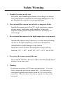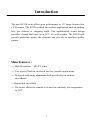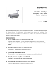
1
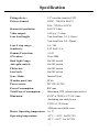
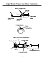
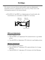
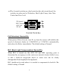
EZ350
Hi gh Resol uti on Weatherproof Camera
User’s Manual
and
Operation Instructions
Notice
This manual is presented to the users of EZ350 by EverFocus Electronics
Corp. With years of engineering researches, EverFocus has spared no effort
to provide the high quality products to the worldwide users. For the policy
of continual product improvement, EverFocus reserves the right to make
changes to the product specifications and documentation without notice.
All the components of the products, including accessories, components, and
outlook, are based on the agreements of each deals to satisfy all kinds of
users. Meanwhile, please be advised that every step of operation must
follow the instruction of this manual to keep EZ350 working under the best
condition. Please notice that EverFocus will not be charged any claims or
renewing cases resulted from inappropriate operation.
Table of Contents
Safety Warning … … … … … … … … … … … … … … … … 1
Introduction… … … … … … … … … … … … … … … … … ..2
Specification… … … … … … … … … … … … … … … … … .3
Major Parts Names… ..… … … … … … … … … … … .… ..4
Installation Instructions… … … … … … … … … … .… .… 5
Settings… … … … … … … … … … … … … … … … … … … .7
Safety Warning
1. Handle the camera with care.
Be careful when handling the camera, do not drop it or subject
it to strong shock or vibration to prevent any damages to it. Do
not disassemble it or place it on an unstable base.
2.
Do not install the camera near electric or magnetic fields.
Installed the camera away from TV, radio transmitter, magnet,
electric motor, transformer, audio speakers because the
magnetic fields generate from above devices will distort the
video image.
3. Do not install the camera in the high temperature environment.
Installed the camera away from stoves, or other heat generating
devices as the high temperature could cause deformation,
discoloration or other damages of the camera.
Install the camera at where the temperature range will stay
between -35℃~ +50℃ for DC12V, -45℃~+50℃ for AC24V
.
4. Never face the camera toward the sun.
Never aim the camera at the sun or other extremely bright objects
whether it is in use or not.
5. Cleaning
Do not touch the surface of CCD sensor by hand directly. Use a soft
cloth to remove the dirt from the camera body. Use lens tissue or a
cotton tipped applicator and ethanol to clean the CCD sensor and the
camera lens. When the camera is not in use, put the cover cap on the
lens mount.
1
Introduction
The new EZ350 series offers great performance in 1/3”image format color
CCD camera. The EZ350 is ideal for outdoor applications such as parking
lots, gas stations or shopping malls. The sophisticated circuit design
provides a heater that turns on at 10℃ for cold weather. The EZ350 will
provide protection against the elements and provide an excellent quality
picture.
Main Features :
??
High Resolution: 480 TV Lines.
??
Two types of built-in vari-focal lens for versatile applications.
??
Designed with sturdy aluminum shell specifically for outdoor
surveillance.
??
Removable sun shield.
??
The heater allows the camera to be used in extremely low temperature
to -46°
C.
2
Specification
Pickup device:
1/3” interline transfer CCD
Picture element:
NTSC: 768(H) x 494(V)
PAL: 752(H) x 582(V)
Horizontal resolution:
480 TV Lines
Video output:
1.0Vp-p, 75 ohm
Lens focal length:
Vari-focal lens f=3.5~8mm /
Vari-focal lens f=9~22mm
Lens F stop range:
1.6~360
Sensitivity:
1.42 lux/F=1.6
Gamma Correction:
>0.45
S/N ration:
Over 48db
Back light Comp.:
On/Off switch
Auto gain control:
On/Off switch
Flickerless:
On/Off switch
Line Lock:
On/Off switch
Sync. Mode:
Internal Sync.
Weather proof rate
IP 66
Power source:
DC12V/AC24V
Power Consumption:
5W max
Total Power Consumption:
Maximum 12W (when heater active)
Dimension:
83(W) x 70(H) x 172.5(L) mm
-Including sun shield cover
57(D) x 132(L)mm
-Without sun shield cover
Heater Operating temperature
10 °
C
Operating temperature:
-35℃~ +50℃ for DC12V
-45℃~+50℃ for AC24V
3
Major Parts Names and Their Functions
Back Fixing Plate
Swivel
Screw
Sun Shield
Cover
Set-Screw
Assembly
Screw
Mounting
Base
Fixing Screw
Front
Fixing Plate
IRIS ALC/Level Adjustment
Focus Zoom
O-ring Seal
Lens
Heater
Mounting Bracket
Control Switch
4
Installation Instructions
1. Using the supplied screws, mount the bracket base on the desired
location.
2. Connect the BNC connector of the camera to a monitor or other video
device through a 75 ohm type coaxial cable with BNC female connector
at cable extension.
3. Connect the AC24V or DC12V regulated power source of the camera
(power jack) to the power-in jack with 2mm plug. For DC12V power
source, please make sure the power plug is center+ outer- for heater
normal operation.
4. Our factory settings is for you to get the best image within about 3~5
meters (for veri-focal lens f=3.5~8mm) or 5~10 meters (for veri-focal
lens f=9~22mm) . If it is out of focus, or any other adjustment is required,
follow the procedures below.
a. Remove the fixing screw in the front, which hold the sun shield
cover. Remove the sun shield cover.
b. Twist open and carefully remove the housing cover.
(Please pay attention to prevent damage to the “O”-Ring seal.)
c. Loosen the focal lens and focus locking screws.
d. Adjust the lens to bring the subject into focus.
(Caution: Heater elements could be hot! When camera power is on,
use caution when adjusting the camera.)
e. Retighten the screws.
f. Please refer to the Settings section for the details of the other
adjustments. Adjust accordingly if necessary.
5
g. When all the adjustments and settings are completed, overlaying the
cover gently. Be careful not to damage to the “O”-Ring and camera
components.
h. To reassemble the sun shield, match the hole on the sun shield to
the back fixing plate of camera, Fix the screw on the front fixing plate.
Make sure the wider side of the fixing plate holds the edge of the
camera well.
5. Attach the camera onto the mounting bracket.
6. Loosen the swivel screw and point the camera to the desired direction.
7. Tighten the swivel screw. To strengthen the fixing power of the swivel
screw, tighten the set-screw with the set-screw wrench. (supplied)
Notes:
(A) Make wiring connections only after it has been determined that
power has been disconnected.
(A) There is a desiccant pack attached to the housing base under the
camera which is designed to absorb any moisture trapped inside the
housing during adjustment.
To avoid excessive moisture build up,
it is recommended that the camera not be installed in rainy or
excessively damp conditions.
It is also advisable to limit the
number of times the housing cover is removed.
The desiccant pack
can be replaced if condensation develops inside the housing.
6
Settings
The camera is set up at factory and normally requires no adjustments.
Sometimes, however, adjustments may be necessary. Please refer to the
following description for the function details.
??The IRIS ALC and IRIS Level adjustments are located on the side
circuit board, use a screwdriver to adjust if it’s necessary.
IRIS Level
Adjustment
IRIS ALC
Adjustment
Control Switches
IRIS Level Adjustment
To adjust brightness level –
?? Turn the IRIS Level Adjustment VR counterclockwise to get darker
picture.
?? Turn the IRIS level adjustment VR clockwise to get brighter picture.
IRIS ALC Adjustment
To select light metering method –
?? Turn the IRIS ALC Adjustment VR counterclockwise for Average
Metering.
?? Turn the IRIS ALC Adjustment VR clockwise for Peak Metering.
7
??The 4 control switches are also located on the side circuit board, the
switches in orders are for Flickerless, Back Light Comp, Auto Gain
Control and Line Lock.
FL Normal
BLC Normal
AGC Off
LL Off
On
On
On
On
Control Switches
FL(Flickerless) Normal/On
When picture flicker fiercely, turn FL on, then the camera will stabilize the
speed of electronic shutter at 1/100(NTSC) or 1/120(PAL) automatically,
and reduce the flicker immediately. The default setting is Normal.
BLC (Back Light Compensation) Normal/On
When BLC is turned on, the AGC, ES and IRIS operating point is
determined by averaging over the center area instead of entire field-of-view,
so that a dimly-lit foreground object at center area can be clearly
distinguished from brightly-lit backgrounds.
BLC should not be used unless it is needed to compensate for back-lit. The
default setting is Normal.
8
AGC (Automatic Gain Control) Off/On
AGC ON: The sensitivity increases automatically when light is low.
AGC OFF: A-low-noise picture is obtained under a low light condition.
The default setting is On.
LL (Line-Lock) Off/On
To select the sync mode between Internal Sync.(LL off) and Line-Lock
(LL on).
Set the line-lock off, the camera will synchronize to the internal time base.
Set the line-lock on, the camera’s vertical synchronization can be driven by
the AC signal in the power lines.
The default setting is Off
Note: Line-Lock sync mode operation is possible only when used with an
AC power source; it’s not possible with a DC power source.
9
EverFocus Electronics Corp.
Head Office:
European Office:
12F, No.79 Sec. 1 Shin-Tai Wu Road,
Hsi-Chi, Taipei, Taiwan
TEL: +886-2-26982334
FAX: +886-2-26982380
www.everfocus.com.tw
Albert-Einstein-Strasse 1
D-46446 Emmerich, Germany
www.everfocus.de
TEL: 49-2822-9394-0
FAX: 49-2822939495
USA Office:
Beijing Office:
2445 Huntington Drive, San Marino,
CA 91108, U.S.A.
TEL: +1-626-844-8888
FAX: +1-626-844-8838
www.everfocus.com
Room 609, Technology Trade
Building,
Shandgdi Information Industry Base,
Haidian District, Beijing,China
TEL: +86-10-62973336
FAX: +86-10-62971432
www.everfocus.com.cn
Japan Office:
1809 WBG MARIBU East 18F,
2-6 Nakase.Mihama-ku.
Chiba city 261-7118, Japan
TEL : +81-43-212-8188
FAX : +81-43-297-0081
www.everfocus.com.tw
MZ35G00100