1
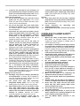
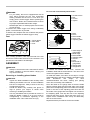
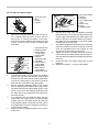
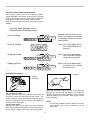
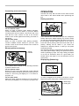
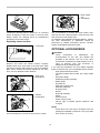
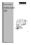
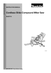
ENGLISH (Original instructions)
INSTRUCTION MANUAL
Cordless Planer
DKP140
DKP180
011751
IMPORTANT: Read Before Using.
1
ENGLISH (Original instructions)
SPECIFICATIONS
Model
DKP140
DKP180
Planing width
82 mm
Planing depth
1.6 mm
2 mm
Shiplapping depth
9 mm
No load speed (min-1)
15,000
Overall length
329 mm
Net weight
3.3 kg
333 mm
3.4 kg
Rated voltage
D.C. 14.4 V
D.C. 18 V
• Due to our continuing program of research and development, the specifications herein are subject to change without notice.
• Specifications and battery cartridge may differ from country to country.
• Weight, with battery cartridge, according to EPTA-Procedure 01/2003
END004-6
Wear ear protection
Symbols
The following show the symbols used for the equipment.
Be sure that you understand their meaning before use.
・ Read instruction manual.
Cd
Ni-MH
Li-ion
・
ENG900-1
Vibration
The vibration total value (tri-axial
determined according to EN60745:
Only for EU countries
Do not dispose of electric equipment or
battery pack together with household
waste material!
In observance of the European
Directives, on Waste Electric and
Electronic Equipment and Batteries and
Accumulators and Waste Batteries and
Accumulators and their implementation
in accordance with national laws, electric
equipment and batteries and battery
pack(s) that have reached the end of
their life must be collected separately
and returned to an environmentally
compatible recycling facility.
vector
sum)
Model DKP140
Work mode : planing softwood
Vibration emission (ah) : 3.5 m/s2
Uncertainty (K) : 1.5 m/s2
Model DKP180
Work mode : planing softwood
Vibration emission (ah) : 4.5 m/s2
Uncertainty (K) : 1.5 m/s2
ENG901-1
•
ENE001-1
Intended use
The tool is intended for planing wood.
•
The declared vibration emission value has been
measured in accordance with the standard test
method and may be used for comparing one tool
with another.
The declared vibration emission value may also be
used in a preliminary assessment of exposure.
ENG905-1
Noise
The typical A-weighted noise level determined according
to EN60745:
•
Model DKP140
Sound pressure level (LpA) : 80 dB (A)
Uncertainty (K) : 3 dB (A)
The noise level under working may exceed 80 dB (A).
•
Model DKP180
Sound pressure level (LpA) : 84 dB (A)
Sound power level (LWA) : 95 dB (A)
Uncertainty (K) : 3 dB (A)
2
WARNING:
The vibration emission during actual use of the
power tool can differ from the declared emission
value depending on the ways in which the tool is
used.
Be sure to identify safety measures to protect the
operator that are based on an estimation of
exposure in the actual conditions of use (taking
account of all parts of the operating cycle such as
the times when the tool is switched off and when it
is running idle in addition to the trigger time).
ENH101-16
Electrical safety
4.
Power tool plugs must match the outlet. Never
modify the plug in any way. Do not use any
adapter plugs with earthed (grounded) power
tools. Unmodified plugs and matching outlets will
reduce risk of electric shock.
5.
Avoid body contact with earthed or grounded
surfaces such as pipes, radiators, ranges and
refrigerators. There is an increased risk of
electric shock if your body is earthed or grounded.
6.
Do not expose power tools to rain or wet
conditions. Water entering a power tool will
increase the risk of electric shock.
7.
Do not abuse the cord. Never use the cord for
carrying, pulling or unplugging the power tool.
Keep cord away from heat, oil, sharp edges or
moving parts. Damaged or entangled cords
increase the risk of electric shock.
8.
When operating a power tool outdoors, use an
extension cord suitable for outdoor use. Use of
a cord suitable for outdoor use reduces the risk of
electric shock.
9.
If operating a power tool in a damp location is
unavoidable, use a ground fault circuit
interrupter (GFCI) protected supply. Use of an
GFCI reduces the risk of electric shock.
Personal safety
10. Stay alert, watch what you are doing and use
common sense when operating a power tool. Do
not use a power tool while you are tired or under
the influence of drugs, alcohol or medication. A
moment of inattention while operating power tools
may result in serious personal injury.
11. Use personal protective equipment. Always
wear eye protection. Protective equipment such
as dust mask, non-skid safety shoes, hard hat, or
hearing protection used for appropriate conditions
will reduce personal injuries.
12. Prevent unintentional starting. Ensure the
switch is in the off-position before connecting
to power source and/or battery pack, picking
up or carrying the tool. Carrying power tools
with your finger on the switch or energising power
tools that have the switch on invites accidents.
13. Remove any adjusting key or wrench before
turning the power tool on. A wrench or a key left
attached to a rotating part of the power tool may
result in personal injury.
14. Do not overreach. Keep proper footing and
balance at all times. This enables better control
of the power tool in unexpected situations.
15. Dress properly. Do not wear loose clothing or
jewellery. Keep your hair, clothing, and gloves
away from moving parts. Loose clothes, jewellery
or long hair can be caught in moving parts.
For European countries only
EC Declaration of Conformity
We Makita Corporation as the responsible
manufacturer declare that the following Makita
machine(s):
Designation of Machine:
Cordless Planer
Model No./ Type: DKP140, DKP180
are of series production and
Conforms to the following European Directives:
2006/42/EC
And are manufactured in accordance with the following
standards or standardised documents:
EN60745
The technical documentation is kept by:
Makita International Europe Ltd.
Technical Department,
Michigan Drive, Tongwell,
Milton Keynes, Bucks MK15 8JD, England
06.06.2013
000230
Tomoyasu Kato
Director
Makita Corporation
3-11-8, Sumiyoshi-cho,
Anjo, Aichi, 446-8502, JAPAN
GEA006-2
General Power Tool Safety
Warnings
WARNING Read all safety warnings and all
instructions. Failure to follow the warnings and instructions
may result in electric shock, fire and/or serious injury.
Save all warnings and
instructions for future reference.
The term "power tool" in the warnings refers to your
mains-operated (corded) power tool or battery-operated
(cordless) power tool.
Work area safety
1.
Keep work area clean and well lit. Cluttered or
dark areas invite accidents.
2.
Do not operate power tools in explosive
atmospheres, such as in the presence of
flammable liquids, gases or dust. Power tools
create sparks which may ignite the dust or fumes.
3.
Keep children and bystanders away while
operating a power tool. Distractions can cause
you to lose control.
3
contact accidentally occurs, flush with water. If
liquid contacts eyes, additionally seek medical
help. Liquid ejected from the battery may cause
irritation or burns.
Service
28. Have your power tool serviced by a qualified
repair person using only identical replacement
parts. This will ensure that the safety of the power
tool is maintained.
29. Follow instruction for lubricating and
changing accessories.
30. Keep handles dry, clean and free from oil and
grease.
16.
If devices are provided for the connection of
dust extraction and collection facilities, ensure
these are connected and properly used. Use of
dust collection can reduce dust-related hazards.
Power tool use and care
17. Do not force the power tool. Use the correct
power tool for your application. The correct
power tool will do the job better and safer at the
rate for which it was designed.
18. Do not use the power tool if the switch does
not turn it on and off. Any power tool that cannot
be controlled with the switch is dangerous and
must be repaired.
19. Disconnect the plug from the power source
and/or the battery pack from the power tool
before making any adjustments, changing
accessories, or storing power tools. Such
preventive safety measures reduce the risk of
starting the power tool accidentally.
20. Store idle power tools out of the reach of
children and do not allow persons unfamiliar
with the power tool or these instructions to
operate the power tool. Power tools are
dangerous in the hands of untrained users.
21. Maintain power tools. Check for misalignment
or binding of moving parts, breakage of parts
and any other condition that may affect the
power tool’s operation. If damaged, have the
power tool repaired before use. Many accidents
are caused by poorly maintained power tools.
22. Keep cutting tools sharp and clean. Properly
maintained cutting tools with sharp cutting edges
are less likely to bind and are easier to control.
23. Use the power tool, accessories and tool bits
etc. in accordance with these instructions,
taking into account the working conditions
and the work to be performed. Use of the power
tool for operations different from those intended
could result in a hazardous situation.
Battery tool use and care
24. Recharge only with the charger specified by
the manufacturer. A charger that is suitable for
one type of battery pack may create a risk of fire
when used with another battery pack.
25. Use power tools only with specifically
designated battery packs. Use of any other
battery packs may create a risk of injury and fire.
26. When battery pack is not in use, keep it away
from other metal objects, like paper clips,
coins, keys, nails, screws or other small metal
objects, that can make a connection from one
terminal to another. Shorting the battery
terminals together may cause burns or a fire.
27. Under abusive conditions, liquid may be
ejected from the battery; avoid contact. If
GEB064-2
CORDLESS PLANER SAFETY
WARNINGS
1.
2.
3.
4.
5.
6.
7.
8.
9.
10.
11.
12.
13.
14.
15.
16.
4
Wait for the cutter to stop before setting the
tool down. An exposed rotating cutter may
engage the surface leading to possible loss of
control and serious injury.
Use clamps or another practical way to secure
and support the workpiece to a stable platform.
Holding the work by your hand or against the body
leaves it unstable and may lead to loss of control.
Rags, cloth, cord, string and the like should
never be left around the work area.
Avoid cutting nails. Inspect for and remove all
nails from the workpiece before operation.
Use only sharp blades. Handle the blades very
carefully.
Be sure the blade installation bolts are
securely tightened before operation.
Hold the tool firmly with both hands.
Keep hands away from rotating parts.
Before using the tool on an actual workpiece,
let it run for a while. Watch for vibration or
wobbling that could indicate poor installation
or a poorly balanced blade.
Make sure the blade is not contacting the
workpiece before the switch is turned on.
Wait until the blade attains full speed before
cutting.
Always switch off and wait for the blades to
come to a complete stop before any adjusting.
Never stick your finger into the chip chute.
Chute may jam when cutting damp wood.
Clean out chips with a stick.
Do not leave the tool running. Operate the tool
only when hand-held.
Always change both blades or covers on the
drum, otherwise the resulting imbalance will
cause vibration and shorten tool life.
Use only Makita blades specified in this
manual.
17.
Always use the correct dust mask/respirator
for the material and application you are
working with.
SAVE THESE INSTRUCTIONS.
Tips for maintaining maximum battery life
1.
SAVE THESE INSTRUCTIONS.
WARNING:
DO NOT let comfort or familiarity with product
(gained from repeated use) replace strict adherence
to safety rules for the subject product.
MISUSE or failure to follow the safety rules stated in
this instruction manual may cause serious personal
injury.
2.
3.
ENC007-8
IMPORTANT SAFETY
INSTRUCTIONS
4.
FOR BATTERY CARTRIDGE
1.
Before using battery cartridge, read all
instructions and cautionary markings on (1)
battery charger, (2) battery, and (3) product
using battery.
2.
Do not disassemble battery cartridge.
3.
If operating time has become excessively
shorter, stop operating immediately. It may
result in a risk of overheating, possible burns
and even an explosion.
4.
If electrolyte gets into your eyes, rinse them
out with clear water and seek medical
attention right away. It may result in loss of
your eyesight.
5.
Do not short the battery cartridge:
(1) Do not touch the terminals with any
conductive material.
(2) Avoid storing battery cartridge in a
container with other metal objects such as
nails, coins, etc.
(3) Do not expose battery cartridge to water
or rain.
A battery short can cause a large current flow,
overheating, possible burns and even a
breakdown.
6.
Do not store the tool and battery cartridge in
locations where the temperature may reach or
exceed 50 ゚ C (122 ゚ F).
7.
Do not incinerate the battery cartridge even if
it is severely damaged or is completely worn
out. The battery cartridge can explode in a fire.
8.
Be careful not to drop or strike battery.
9.
Do not use a damaged battery.
10. Follow your local regulations relating to
disposal of battery.
5
Charge the battery cartridge before completely
discharged.
Always stop tool operation and charge the
battery cartridge when you notice less tool
power.
Never recharge a fully charged battery
cartridge.
Overcharging shortens the battery service life.
Charge the battery cartridge with room
temperature at 10 ゚ C - 40 ゚ C (50 ゚ F - 104 ゚ F).
Let a hot battery cartridge cool down before
charging it.
Charge the battery cartridge once in every six
months if you do not use it for a long period of
time.
•
When the tool is overloaded:
At this time, release the switch trigger,
remove the battery cartridge and remove
causes of overload and then pull the switch
trigger again to restart.
When battery cells get hot:
If any operation of the switch trigger, the
motor will remain stopped. At this time, stop
use of the tool and cool or charge the battery
cartridge after removing it from the tool.
When the remaining battery capacity gets low:
If any operation of the switch trigger, the motor
will remain stopped. At this time, remove the
battery cartridge from the tool and charge it .
•
FUNCTIONAL DESCRIPTION
CAUTION:
Always be sure that the tool is switched off and the
battery cartridge is removed before adjusting or
checking function on the tool.
•
Installing or removing battery cartridge
1. Button
2. Red indicator
3. Battery cartridge
1
2
•
Adjusting depth of cut
3
1. Pointer
2. Knob
1
011755
•
•
•
•
Always switch off the tool before installing or
removing of the battery cartridge.
To remove the battery cartridge, slide it from the tool
while sliding the button on the front of the cartridge.
To install the battery cartridge, align the tongue on
the battery cartridge with the groove in the housing
and slip it into place. Always insert it all the way
until it locks in place with a little click. If you can
see the red indicator on the upper side of the
button, it is not locked completely. Install it fully
until the red indicator cannot be seen. If not, it may
accidentally fall out of the tool, causing injury to
you or someone around you.
Do not use force when installing the battery
cartridge. If the cartridge does not slide in easily, it
is not being inserted correctly.
2
011737
Depth of cut may be adjusted by simply turning the knob
on the front of the tool so that the pointer points the
desired depth of cut.
Switch action
1
2
1. Lock-off lever
2. Switch trigger
Battery protection system
(Battery cartridge with a star mark)
1
1. Star mark
011738
CAUTION:
Before installing the battery cartridge into the tool,
always check to see that the switch trigger
actuates properly and returns to the "OFF" position
when released.
•
Do not pull the switch trigger hard without pressing
the lock-off lever. This can cause switch breakage.
To prevent the switch trigger from being accidentally
pulled, a lock-off lever is provided. To start the tool, slide
the lock-off lever and pull the switch trigger. Release the
switch trigger to stop.
•
011389
The battery cartridge with a star mark is equipped with
the protection system, which automatically cuts off the
output power for its long service life.
The tool stops during operation when the tool and/or
battery are placed under the following situation. This is
caused by the activation of protection system and does
not show the tool trouble.
6
For tool with conventional planer blades
WARNING:
For your safety, this tool is equipped with lock-off
lever which prevents the tool from unintended
starting. NEVER use the tool if it runs when you
simply pull the switch trigger without pressing the
lock-off lever. Return tool a MAKITA service center
for proper repairs BEFORE further usage.
•
NEVER tape down or defeat purpose and function
of lock-off lever.
To prevent the switch trigger from being accidentally
pulled, a lock-off button is provided.
To start the tool, depress the lock-off button and pull the
switch trigger. Release the switch trigger to stop.
•
1
4
1. Socket wrench
2. Bolt
3. Loosen
4. Tighten
3
2
011740
1
Foot
1. Planer blade
2. Rear base
3. Foot
2
3
4
5
1. Bolts
2. Drum
3. Planer blade
4. Drum cover
5. Adjusting plate
002555
1
2
3
011739
2
3
4
5
6
7
After a cutting operation, raise the back side of the tool
and a foot comes under the level of the rear base. This
prevents the tool blades to be damaged.
ASSEMBLY
1
8
9
•
CAUTION:
Always be sure that the tool is switched off and the
battery cartridge is removed before carrying out
any work on the tool.
002556
To remove the blades on the drum, unscrew the
installation bolts with the socket wrench. The drum cover
comes off together with the blades.
To install the blades, first clean out all chips or foreign
matter adhering to the drum or blades. Use blades of the
same
dimensions
and
weight,
or
drum
oscillation/vibration will result, causing poor planing
action and, eventually, tool breakdown.
Place the blade on the gauge base so that the blade
edge is perfectly flush with the inside edge of the gauge
plate. Place the adjusting plate on the blade, then simply
press in the heel of the adjusting plate flush with the
back side of the gauge base and tighten two screws on
the adjusting plate. Now slip the heel of the adjusting
plate into the drum groove, then fit the drum cover on it.
Tighten all the installation bolts evenly and alternately
with the socket wrench.
Repeat the above procedures for the other blade.
Removing or installing planer blades
•
•
•
1. Inside edge of
gauge plate
2. Blade edge
3. Planer blade
4. Adjusting plate
5. Screws
6. Heel
7. Back side of
gauge base
8. Gauge plate
9. Gauge base
CAUTION:
Tighten the blade installation bolts carefully when
attaching the blades to the tool. A loose installation
bolt can be dangerous. Always check to see they
are tightened securely.
Handle the blades very carefully. Use gloves or
rags to protect your fingers or hands when
removing or installing the blades.
Use only the Makita wrench provided to remove or
install the blades. Failure to do so may result in
overtightening or insufficient tightening of the
installation bolts. This could cause an injury.
7
For tool with mini planer blades
6
1
1
4
1. Socket wrench
2. Bolt
3. Loosen
4. Tighten
3
5
7
2
4
3
2
1. Mini planer blade
2. Groove
3. Set plate
4. Hex. flange head
bolts
5. Drum cover
6. Drum
7. Adjusting plate
002566
6.
011740
1.
Remove the existing blade, if the tool has been in
use, carefully clean the drum surfaces and the
drum cover. To remove the blades on the drum,
unscrew the three installation bolts with the socket
wrench. The drum cover comes off together with
the blades.
1
2
3
4
5
6
7
8
9
10
7.
1. Pan head screw
2. Adjusting plate
3. Planer blade
locating lugs
4. Gauge plate
5. Heel of
adjusting plate
6. Set plate
7. Inside flank of
gauge plate
8. Gauge base
9. Back side of
gauge base
10. Mini planer blade
8.
9.
10.
002565
2.
3.
4.
5.
To install the blades, loosely attach the adjusting
plate to the set plate with the pan head screws
and set the mini planer blade on the gauge base
so that the cutting edge of the blade is perfectly
flush with the inside flank of the gauge plate.
Set the adjusting plate/set plate on the gauge
base so that the planer blade locating lugs on the
set plate rest in the mini planer blade groove, then
press in the heel of the adjusting plate flush with
the back side of the gauge base and tighten the
pan head screws.
It is important that the blade sits flush with the
inside flank of the gauge plate, the planer blade
locating lugs sit in the blade groove and the heel
of the adjusting plate is flush with the back side of
the gauge base. Check this alignment carefully to
ensure uniform cutting.
Slip the heel of the adjusting plate into the groove
of the drum.
8
Set the drum cover over the adjusting plate/set
plate and screw in the three hex flange head bolts
so that a gap exists between the drum and the set
plate to slide the mini planer blade into position.
The blade will be positioned by the planer blade
locating lugs on the set plate.
The blade's lengthwise adjustment will need to be
manually positioned so that the blade ends are
clear and equidistant from the housing on one
side and the metal bracket on the other.
Tighten the three hex flange head bolts (with the
socket wrench provided) and rotate the drum to
check clearances between the blade ends and the
tool body.
Check the three hex flange head bolts for final
tightness.
Repeat procedures 1 - 9 for the other blade.
For the correct planer blade setting
Your planing surface will end up rough and uneven,
unless the blade is set properly and securely. The blade
must be mounted so that the cutting edge is absolutely
level, that is, parallel to the surface of the rear base.
Refer to some examples below for proper and improper
settings.
(A) Front base (Movable shoe)
(B) Rear base (Stationary shoe)
Correct setting
(A)
(B)
Although this side view cannot
show it, the edges of the blades
run perfectly parallel to the rear
base surface.
Cause: One or both blades fails to
have edge parallel to rear
base line.
Nicks in surface
Gouging at start
(A)
Gouging at end
(A)
(B)
Cause: One or both blade edges
fails to protrude enough in
relation to rear base line.
(B)
Cause: One or both blade edges
protrudes too far in relation
to rear base line.
EN0004-1
Dust bag (accessory)
1. Fastener
1. Nozzle
2. Dust bag
1
1
2
007802
When the dust bag is about half full, remove the dust
bag from the tool and pull the fastener out. Empty the
dust bag of its contents, tapping it lightly so as to remove
particles adhering to the insides which might hamper
further collection.
011741
For tool without nozzle
Remove the chip cover and install the nozzle (optional
accessory). Attach the dust bag onto the nozzle . The
nozzle is tapered. When attaching the dust bag, push it
onto the nozzle firmly as far as it will go to prevent it from
coming off during operation.
For tool with nozzle
Attach the dust bag onto the nozzle. The nozzle is tapered.
When attaching the dust bag, push it onto the nozzle firmly as
far as it will go to prevent it from coming off during operation.
NOTE:
•
If you connect a Makita vacuum cleaner to this tool,
more efficient and cleaner operations can be
performed.
9
Connecting a vacuum cleaner
OPERATION
Hold the tool firmly with one hand on the knob and the
other hand on the switch handle when performing the
tool.
Planing operation
1. Start
2. End
1
011757
For tool without nozzle
When you wish to perform clean planing operation,
connect a Makita vacuum cleaner to your tool. Before
connecting the vacuum cleaner, remove the chip cover
from the tool. Then connect a hose of the vacuum
cleaner to the nozzle (optional accessory) as shown in
the figures.
For tool with nozzle
When you wish to perform clean planing operation,
connect a Makita vacuum cleaner to your tool. Then
connect a hose of the vacuum cleaner to the nozzle as
shown in the figures.
2
011759
First, rest the tool front base flat upon the workpiece
surface without the blades making any contact. Switch
on and wait until the blades attain full speed. Then move
the tool gently forward. Apply pressure on the front of
tool at the start of planing, and at the back at the end of
planing. Planing will be easier if you incline the
workpiece in stationary fashion, so that you can plane
somewhat downhill.
The speed and depth of cut determine the kind of finish.
The power planer keeps cutting at a speed that will not
result in jamming by chips. For rough cutting, the depth
of cut can be increased, while for a good finish you
should reduce the depth of cut and advance the tool
more slowly.
Elbow (optional accessory)
1. Elbow
2. Nozzle
Shiplapping (Rabbeting)
1
2
011758
Use of elbow allows change of chip discharge direction
to perform cleaner work.
For tool without nozzle
Remove the chip cover and install the nozzle (optional
accessory). Attach the elbow (optional accessory) on the
nozzle of the tool by just slipping on it. To remove it,
just pull it out.
For tool with nozzle
Attach the elbow (optional accessory) on the nozzle of
the tool by just slipping on it. To remove it, just pull it out.
002580
To make a stepped cut as shown in the figure, use the
edge fence (guide rule) which is obtained as accessory.
1. Blade edge
2. Cutting line
2
1
011752
10
Draw a cutting line on the workpiece. Insert the edge
fence into the hole in the front of the tool. Align the blade
edge with the cutting line.
2
1. Screw
2. Edge fence
(optional
accessory)
1
011748
To make a chamfering cut as shown in the figure, align
the "V" groove in the front base with the edge of the
workpiece and plane it.
011760
Adjust the edge fence until it comes in contact with the
side of the workpiece, then secure it by tightening the
screw.
MAINTENANCE
•
•
CAUTION:
Always be sure that the tool is switched off and the
battery cartridge is removed before attempting to
perform inspection or maintenance.
Never use gasoline, benzine, thinner, alcohol or
the like. Discoloration, deformation or cracks may
result.
Sharpening the planer blades
For conventional blades only
011761
When planing, move the tool with the edge fence flush
with the side of the workpiece. Otherwise uneven
planing may result.
Maximum shiplapping (rabbeting) depth is 9 mm.
1. Sharpening
holder
1
002588
Always keep your blades sharp for the best performance
possible. Use the sharpening holder (optional
accessory) to remove nicks and produce a fine edge.
010183
You may wish to add to the length of the fence by
attaching an extra piece of wood. Convenient holes are
provided in the fence for this purpose, and also for
attaching an extension guide (optional accessory).
1
5
2
Chamfering
3
1. Wing nut
2. Blade (A)
3. Blade (B)
4. Side (D)
5. Side (C)
4
002589
First, loosen the two wing nuts on the holder and insert
the blades (A) and (B), so that they contact the sides (C)
and (D). Then tighten the wing nuts.
003634
11
1. Brush holder
cap
2. Screwdriver
1
2
002590
011750
Immerse the dressing stone in water for 2 or 3 minutes
before sharpening. Hold the holder so that the both
blades contact the dressing stone for simultaneous
sharpening at the same angle.
Use a screwdriver to remove the brush holder caps.
Take out the worn carbon brushes, insert the new ones
and secure the brush holder caps.
To maintain product SAFETY and RELIABILITY, repairs,
any other maintenance or adjustment should be
performed by Makita Authorized Service Centers,
always using Makita replacement parts.
Replacing carbon brushes
1. Limit mark
OPTIONAL ACCESSORIES
CAUTION:
These
accessories
or
attachments
are
recommended for use with your Makita tool
specified in this manual. The use of any other
accessories or attachments might present a risk of
injury to persons. Only use accessory or
attachment for its stated purpose.
If you need any assistance for more details regarding
these accessories, ask your local Makita Service Center.
•
High-speed steel Planer blade
•
Tungsten-carbide Planer blade (For longer blade
life)
•
Mini planer blade
•
Sharpening holder assembly
•
Blade gauge
•
Set plate set
•
Edge fence (Guide rule)
•
Extension guide set
•
Dressing stone
•
Nozzle
•
Dust bag assembly
•
Elbow
•
Socket wrench
•
Plastic carrying case
•
Various type of Makita genuine batteries and
chargers
•
1
001145
Remove and check the carbon brushes regularly.
Replace when they wear down to the limit mark. Keep
the carbon brushes clean and free to slip in the holders.
Both carbon brushes should be replaced at the same
time. Use only identical carbon brushes.
1. Chip cover
2. Screwdriver
1
2
011749
1. Nozzle
2. Screwdriver
1
2
NOTE:
•
Some items in the list may be included in the tool
package as standard accessories. They may differ
from country to country.
011753
Use a screwdriver to remove the chip cover or nozzle.
12
13
14
15
Makita Corporation
Anjo, Aichi, Japan
885273A220
16
www.makita.com