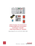
1
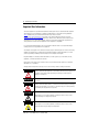
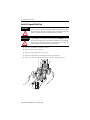
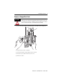
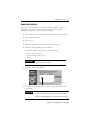
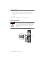
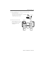
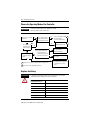
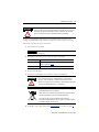
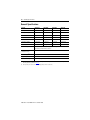
Installation Instructions
GuardLogix Controllers
Catalog Numbers 1756-L61S, 1756-L62S, 1756-L63S,
1756-LSP
Topic
Page
North American Hazardous Location Approval
3
Environment and Enclosure Information
4
General Safety Information
4
Preventing Electrostatic Discharge
4
Prepare the Chassis
5
Make Sure That You Have All of the Components
5
Install a CompactFlash Card
6
Remove a CompactFlash Card
7
Connect the Battery
8
Install the Controller into the Chassis
9
Check the BAT Status Indicator
10
Check the OK Status Indicator
10
Update the Controller
11
Connect a Serial Cable
12
Choose the Operating Mode of the Controller
14
Replace the Battery
14
General Specifications
16
Environmental Specifications
17
Certifications
18
Additional Resources
19
2
GuardLogix Controllers
Important User Information
Solid state equipment has operational characteristics differing from those of electromechanical equipment.
Safety Guidelines for the Application, Installation and Maintenance of Solid State Controls (publication
SGI-1.1 available from your local Rockwell Automation sales office or online at
http://literature.rockwellautomation.com) describes some important differences between solid state
equipment and hard-wired electromechanical devices. Because of this difference, and also because of the
wide variety of uses for solid state equipment, all persons responsible for applying this equipment must
satisfy themselves that each intended application of this equipment is acceptable.
In no event will Rockwell Automation, Inc. be responsible or liable for indirect or consequential damages
resulting from the use or application of this equipment.
The examples and diagrams in this manual are included solely for illustrative purposes. Because of the many
variables and requirements associated with any particular installation, Rockwell Automation, Inc. cannot
assume responsibility or liability for actual use based on the examples and diagrams.
No patent liability is assumed by Rockwell Automation, Inc. with respect to use of information, circuits,
equipment, or software described in this manual.
Reproduction of the contents of this manual, in whole or in part, without written permission of Rockwell
Automation, Inc., is prohibited.
Throughout this manual, when necessary, we use notes to make you aware of safety considerations.
WARNING
IMPORTANT
ATTENTION
Identifies information about practices or circumstances that can cause an explosion in
a hazardous environment, which may lead to personal injury or death, property
damage, or economic loss.
Identifies information that is critical for successful application and understanding of
the product.
Identifies information about practices or circumstances that can lead to personal injury
or death, property damage, or economic loss. Attentions help you to identify a hazard,
avoid a hazard, and recognize the consequences.
SHOCK HAZARD
Labels may be on or inside the equipment, for example, a drive or motor, to alert
people that dangerous voltage may be present.
BURN HAZARD
Labels may be on or inside the equipment, for example, a drive or motor, to alert
people that surfaces may be dangerous temperatures.
Publication 1756-IN045E-EN-P - October 2009
GuardLogix Controllers
3
North American Hazardous Location Approval
The following information applies when operating
this equipment in hazardous locations.
Informations sur l’utilisation de cet équipement en
environnements dangereux .
Products marked “CL I, DIV 2, GP A, B, C, D” are suitable for
use in Class I Division 2 Groups A, B, C, D, Hazardous
Locations and nonhazardous locations only. Each product is
supplied with markings on the rating nameplate indicating
the hazardous location temperature code. When combining
products within a system, the most adverse temperature
code (lowest “T” number) may be used to help determine
the overall temperature code of the system. Combinations
of equipment in your system are subject to investigation by
the local Authority Having Jurisdiction at the time of
installation.
Les produits marqués "CL I, DIV 2, GP A, B, C, D" ne conviennent
qu’à une utilisation en environnements de Classe I Division 2
Groupes A, B, C, D dangereux et non dangereux. Chaque produit
est livré avec des marquages sur sa plaque d’identification qui
indiquent le code de température pour les environnements
dangereux. Lorsque plusieurs produits sont combinés dans un
système, le code de température le plus défavorable (code de
température le plus faible) peut être utilisé pour déterminer le
code de température global du système. Les combinaisons
d’équipements dans le système sont sujettes à inspection par les
autorités locales qualifiées au moment de l’installation.
WARNING
EXPLOSION HAZARD
RISQUE D’EXPLOSION
AVERTISSEMENT
• Do not disconnect equipment
• Couper le courant ou s’assurer que
unless power has been removed
l’environnement est classé non
or the area is known to be
dangereux avant de débrancher
nonhazardous.
l'équipement.
• Do not disconnect connections to
• Couper le courant ou s'assurer que
this equipment unless power has
l’environnement est classé non
been removed or the area is
dangereux avant de débrancher les
known to be nonhazardous.
connecteurs. Fixer tous les
Secure any external connections
connecteurs externes reliés à cet
that mate to this equipment by
équipement à l'aide de vis, loquets
using screws, sliding latches,
coulissants, connecteurs filetés ou
threaded connectors, or other
autres moyens fournis avec ce produit.
• La substitution de composants peut
means provided with this
rendre cet équipement inadapté à une
product.
• Substitution of components may
utilisation en environnement de Classe
impair suitability for Class I,
I, Division 2.
• S’assurer que l’environnement est
Division 2.
• If this product contains batteries,
classé non dangereux avant de
they must only be changed in an
changer les piles.
area known to be nonhazardous.
Publication 1756-IN045E-EN-P - October 2009
4
GuardLogix Controllers
Environment and Enclosure Information
ATTENTION
Environment and Enclosure
This equipment is intended for use in a Pollution Degree 2 industrial environment, in
overvoltage Category II applications (as defined in IEC 60664-1), at altitudes up to 2000 m
(6562 ft) without derating.
This equipment is considered Group 1, Class A industrial equipment according to IEC/CISPR
Publication 11. Without appropriate precautions, there may be difficulties with
electromagnetic compatibility in residential and other environments due to conducted and
radiated disturbances.
This equipment is supplied as open type equipment. It must be mounted within an enclosure
that is suitably designed for those specific environmental conditions that will be present and
appropriately designed to prevent personal injury resulting from accessibility to live parts.
The enclosure must have suitable flame-retardant properties to prevent or minimize the
spread of flame, complying with a flame spread rating of 5VA, V2, V1, V0 (or equivalent) if
non-metallic. The interior of the enclosure must be accessible only by the use of a tool.
Subsequent sections of this publication may contain additional information regarding specific
enclosure type ratings that are required to comply with certain product safety certifications.
In addition to this publication, see:
• Industrial Automation Wiring and Grounding Guidelines, for additional installation
requirements, Allen-Bradley publication 1770-4.1.
• NEMA Standards 250 and IEC 60529, as applicable, for explanations of the degrees of
protection provided by different types of enclosure.
General Safety Information
ATTENTION
Personnel responsible for the application of safety-related Programmable
Electronic Systems (PES) shall be aware of the safety requirements in the
application of the system and shall be trained in using the system.
Preventing Electrostatic Discharge
ATTENTION
This equipment is sensitive to electrostatic discharge, which can cause internal
damage and affect normal operation. Follow these guidelines when you handle
this equipment:
•Touch a grounded object to discharge potential static.
•Wear an approved grounding wriststrap.
•Do not touch connectors or pins on component boards.
•Do not touch circuit components inside the equipment.
•Use a static-safe workstation, if available.
•Store the equipment in appropriate static-safe packaging when not in use.
Publication 1756-IN045E-EN-P - October 2009
GuardLogix Controllers
5
Prepare the Chassis
Before you install a controller, follow these preliminary steps.
1. Install a ControlLogix chassis (catalog number 1756-A4/B, 1756-A7/B,
1756-A10/B, or 1756-A17/B) according to the ControlLogix Chassis
Installation Instructions, publication 1756-IN080.
2. Install one of the following ControlLogix power supplies according to the
corresponding installation instructions.
For this power supply
1756-PA72
1756-PB72
1756-PA75
1756-PB75
Follow the instructions in this publication
ControlLogix Power Supplies Installation Instructions, publication 1756-IN078.
ControlLogix Power Supplies Installation Instructions, publication 1756-IN613.
1756-PA75R(1)
1756-PB75R(1)
(1)
ControlLogix Redundant Power Supplies Installation Instructions, publication 1756-IN573.
A 1756-PSCA2/A redundant power-supply chassis adapter is required for use with redundant power supplies. Refer
to ControlLogix Redundant Power Supplies Chassis Adapter Module Installation Instructions, publication 1756-IN590.
Make Sure That You Have All of the Components
A key and the 1756-BA2 battery ship with the 1756-L6xS
controller, while the 1756-LSP safety partner ships with
the 1756-BA2 battery.
If you want to connect a device to the serial port of the
controller (for example, connect a computer to the
controller), use a 1756-CP3 serial cable.
You can use a 1784-CF64 or 1784-CF128 CompactFlash card with GuardLogix
controllers, firmware revision 18 and later.
IMPORTANT
You must use a 1756-L6xS primary controller and a 1756-LSP safety partner to
achieve SIL 3/PLe.
Publication 1756-IN045E-EN-P - October 2009
6
GuardLogix Controllers
Install a CompactFlash Card
WARNING
ATTENTION
When you insert or remove the CompactFlash card an electrical arc can occur.
This could cause an explosion in hazardous location installations. Be sure that
power is removed or the area is nonhazardous before proceeding.
If you are not sure of the contents of the CompactFlash card, before you install
the card, turn the keyswitch of the controller to the PROG position. Depending
on the contents of the card, a power cycle or fault could cause the card to load
a different project or operating system into the controller.
1. Turn the keyswitch to the PROG position.
2. Open the door of the controller.
3. Push the CompactFlash latch to the left.
4. Insert the CompactFlash card with the A-B logo pointing left.
5. Release the latch and make sure it slides over the CompactFlash card.
COMPACT
FLASH
1-DCD
2-RXD
3-TXD
4-DTR
5-GND
DSR-6
RTS-7
CTS-8
N/C-9
RS232
1
To
Insert 1
2
To Eject
1+2
1
2
UP
BATTERY
DATE
1
2
BATTERY
PORT
Publication 1756-IN045E-EN-P - October 2009
GuardLogix Controllers
7
Remove a CompactFlash Card
WARNING
When you insert or remove the CompactFlash card an electrical arc can occur.
This could cause an explosion in hazardous location installations. Be sure that
power is removed or the area is nonhazardous before proceeding.
1. If the OK status indicator is flashing green, wait until it turns solid green.
COMPACT
FLASH
1-DCD
2-RXD
3-TXD
4-DTR
5-GND
DSR-6
RTS-7
CTS-8
N/C-9
RS232
1
To
Insert 1
2
To Eject
1+2
1
2
UP
BATTERY
DATE
1
2
BATTERY
PORT
2. Open the door of the controller.
3. Push and hold the CompactFlash latch to the left.
4. Push the eject button and remove the card.
5. Release the latch.
Publication 1756-IN045E-EN-P - October 2009
8
GuardLogix Controllers
Connect the Battery
This controller contains a lithium battery, which is intended to be replaced during
the life of the product.
WARNING
When you connect or disconnect the battery, an electrical arc can occur. This
could cause an explosion in hazardous location installations. Be sure that
power is removed or the area is nonhazardous before proceeding.
For safety information on the handling of lithium batteries, including handling
and disposal of leaking batteries, see Guidelines for Handling Lithium
Batteries, publication AG 5-4.
ATTENTION
Store batteries in a cool, dry environment. We recommend 25 °C (77 °F) with
40%…60% relative humidity. You may store batteries for up to 30 days
between -45…85 °C (-49…185 °F), such as during transportation. To avoid
possible leakage, do not store batteries above 60 °C (140 °F) for more than
30 days.
To maintain the memory of the controller while the controller is without power,
connect a battery. Follow the procedure for both the 1756-L6xS controller and
1756-LSP safety partner.
IMPORTANT
Connect only a 1756-BA2 battery to the controller. If you connect a different
battery, you may damage the controller.
Follow these steps to install a new 1756-BA2
battery:
1. Insert the battery as shown.
2. Connect the battery:
+ Red
- Black
1
3. Write the date you installed the battery
on the battery label and attach the
label to the inside of the controller
door.
2
DATE
Publication 1756-IN045E-EN-P - October 2009
3
GuardLogix Controllers
9
Install the Controller into the Chassis
WARNING
When you insert or remove the module while backplane power is on, an
electrical arc can occur. This could cause an explosion in hazardous location
installations.
Be sure that power is removed or the area is nonhazardous before proceeding.
Repeated electrical arcing causes excessive wear to contacts on both the
module and its mating connector. Worn contact may create electrical
resistance that can affect module operation.
1. Insert the key into the 1756-L6xS controller.
2. Turn the key to the PROG position.
1
2
The 1756-LSP safety partner does not have a keyswitch.
3. Align the circuit board with the top and
bottom guides in the chassis.
4. Slide the controller into the chassis.
The controller is fully installed when it is
flush with the power supply or other
installed modules and the top and
bottom latches are engaged.
IMPORTANT
You must install the 1756-LSP safety partner in the slot immediately to
the right of the 1756-L6xS controller. Follow steps 3 and 4 above to
install the 1756-LSP safety partner.
Publication 1756-IN045E-EN-P - October 2009
10
GuardLogix Controllers
Check the BAT Status Indicator
Follow these steps for both the 1756-L6xS controller and 1756-LSP safety partner.
1. Turn on the chassis power.
2. Check the status of the BAT indicator.
If
Then
Off
Go to Update the Controller on page 11.
On
Go to step 3.
BAT Status
Indicator
3. Check that the battery is correctly
connected to the controller or safety
partner.
4. If the BAT status indicator remains on, install another battery.
5. If the BAT status indicator remains on after you complete step 4, contact
your Rockwell Automation representative or local distributor.
Check the OK Status Indicator
Follow these directions for both the 1756-L6xS controller
and 1756-LSP safety partner.
If the OK
Indicator
is
Then
Next step
Solid
green
The controller is OK and its
firmware has been updated.
No further action is required.
Flashing
red
The controller is OK but it
requires a firmware update.
Go to Update the Controller
below.
Publication 1756-IN045E-EN-P - October 2009
OK
Status
Indicator
GuardLogix Controllers
11
Update the Controller
Follow these steps for the 1756-L6xS controller. With ControlFlash, version 8
(RSLogix 5000, version 18) software, the 1756-LSP safety partner updates
automatically, when the 1756-L6xS controller is updated.
1. Connect the controller or chassis to the same network as your workstation.
2. Start ControlFlash software.
3. Choose Next >.
4. Select the catalog number of the controller and choose Next >.
5. Expand the network until you see the controller.
To expand a network one level, do one of the following:
• Double-click the network.
• Select the network and press
→.
• Click + .
IMPORTANT
If the required network is not shown, first configure a driver for
the network in RSLinx software.
6. Select the controller and click OK.
42900
7. Select the revision level to which you want to update the controller and
choose Next >.
IMPORTANT
If the Revision list is empty, download a new upgrade kit. An upgrade
kit ships on a supplemental CD along with RSLogix 5000 software.
Note that some older upgrade kits do not work with new controllers.
Publication 1756-IN045E-EN-P - October 2009
12
GuardLogix Controllers
8. To start the update of the controller, click Finish and then click Yes.
After the controller is updated, the status dialog box displays ‘Update
complete’.
9. Click OK.
10. To close ControlFlash software, click Cancel and then Yes.
Connect a Serial Cable
WARNING
If you connect or disconnect the serial cable with power applied to this
module or the serial device on the other end of the cable, an electrical arc
can occur. This could cause an explosion in hazardous location installations.
Make sure that power is removed or the area is nonhazardous before
proceeding.
Use the serial port on the 1756-L6xS controller for RS-232 communication.
Serial Port
Publication 1756-IN045E-EN-P - October 2009
GuardLogix Controllers
13
To connect a workstation to the serial port, use one of these cables:
• 1756-CP3 serial cable
• 1747-CP3 cable from the SLC product
family (If you use this cable, the
controller door may not close.)
If you make your own serial cable:
• limit the length to 15.2 m (50 ft).
• wire the connectors as shown.
• attach the shield to both
connectors.
Workstation End
Workstation
Controller End
Controller
1 CD
1 CD
2 RDX
2 RDX
3 TXD
3 TXD
4 DTR
4 DTR
COMMON
COMMON
6 DSR
6 DSR
7 RTS
7 RTS
8 CTS
8 CTS
9
9
Publication 1756-IN045E-EN-P - October 2009
14
GuardLogix Controllers
Choose the Operating Mode of the Controller
IMPORTANT • Controller communication occurs regardless of mode.
• All modes produce and consume tags.
Do you need to schedule
a network?
Do you want to prevent
RSLogix 5000 software
from changing the mode?
Yes
No
Turn the keyswitch to PROG A
and then to REM
(Remote Program mode).
No
Yes
B
Do you want to
execute the logic
in the controller?
No
Yes
Do you want the logic
to control the output
devices?
Yes
No
Do you want to prevent
RSLogix 5000 software from:
• changing the mode?
• downloading a project? Yes
• performing online edits?
Turn the keyswitch to
PROG (Program mode).
Turn the keyswitch to RUN
and then to REM
(Remote Run mode).
Turn the keyswitch to RUN
(Run mode).
No
A Outputs revert to their configured state for Program mode.
B This includes Message (MSG) instructions.
A
1. Turn the keyswitch to REM.
2. Go online with RSLogix 5000
software and choose Test
mode.
A
Replace the Battery
ATTENTION
To prevent possible battery leakage, even if the BAT LED is off, replace a
1756-BA2 battery according to the following schedule.
If the temperature 2.54 cm (1 Replace the battery within
in.) below the chassis is
0…35 °C (32 °…95 °F)
No replacement is required until the BAT LED turns on
36…40 °C (96 °…104 °F)
3 years
41…45 °C (105 °…113 °F)
2 years
46…50 °C (114 °…122 °F)
16 months
51…55 °C (123 °…131 °F)
11 months
56…60 °C (132 °…140 °F)
8 months
Publication 1756-IN045E-EN-P - October 2009
GuardLogix Controllers
WARNING
15
When you connect or disconnect the battery, an electrical arc can occur. This
could cause an explosion in hazardous location installations. Be sure that
power is removed or the area is nonhazardous before proceeding.
Because the GuardLogix controller is a 1oo2 controller (two processors), we
strongly recommend that both controller batteries be replaced at the same time.
Follow this procedure to replace the battery.
1. Turn on the chassis power.
IMPORTANT
If you remove the battery and lose power, the project in the controller
will be lost.
2. Determine if the battery shows signs of leakage or damage.
If
Then
Yes
Before handling the battery, review Guidelines for Handling Lithium
Batteries, publication AG-5.4
No
Go to the next step.
3. Remove the old battery.
4. Dispose of the old battery in accordance with local regulations.
ATTENTION
Do not incinerate or dispose of lithium batteries in general trash
collection. They may explode or rupture violently. Follow all local
regulations for disposal of these materials. You are legally responsible
for hazards created during disposal of your battery.
This product contains a sealed lithium battery which may need to be
replaced during the life of the product.
At the end of its life, the battery contained in this product should be
collected separately from any unsorted municipal waste.
The collection and recycling of batteries helps protect the
environment and contributes to the conservation of natural resources
as valuable materials are recovered.
5. To install a new battery, follow the Connect the Battery procedure on page 8.
Publication 1756-IN045E-EN-P - October 2009
16
GuardLogix Controllers
General Specifications
Cat. No.
1756-L61S
1756-L62S
1756-L63S
1756-LSP
Memory - standard tasks
2 MB
4 MB
8 MB
N/A
Memory - safety task
1 MB
1 MB
3.75 MB
(2)
Backplane current at 5V DC
1200 mA
1200 mA
1200 mA
1200 mA
Backplane current at 24V DC
14 mA
14 mA
14 mA
14 mA
Power dissipation
3.5 W
3.5 W
3.5 W
3.5 W
Thermal dissipation
11.9 BTU/hr
11.9 BTU/hr
11.9 BTU/hr
11.9 BTU/hr
Weight, approx.
0.32 kg (11.3 oz)
0.32 kg (11.3 oz)
0.32 kg (11.3 oz)
0.32 kg (11.3 oz)
Isolation voltage
30V (continuous), Basic Insulation Type, RS232 to system
Type tested at 720V DC for 60 seconds
North American
Temperature Code
T4A
Wiring category(1)
Category 2 on communications ports
Programming cable
1756-CP3 or 1747-CP3 serial cable
Replacement battery
1756-BA2 (0.50 g lithium)
(1)
Use this Conductor Category information for planning conductor routing. Refer to Industrial Automation Wiring and
Grounding Guidelines, publication 1770-4.1.
(2)
Safety memory is the same as the corresponding primary controller (1756-L6xS).
Publication 1756-IN045E-EN-P - October 2009
GuardLogix Controllers
17
Environmental Specifications
Attribute
Value
Temperature,
operating
IEC 60068-2-1 (Test Ad, Operating Cold),
IEC 60068-2-2 (Test Bd, Operating Dry Heat),
IEC 60068-2-14 (Test Nb, Operating Thermal Shock):
• 0…60 °C (32…140 °F)
Temperature, storage
IEC 60068-2-1 (Test Ab, Un-packaged Non-operating Cold),
IEC 60068-2-2 (Test Bb, Un-packaged Non-operating Dry Heat),
IEC 60068-2-14 (Test Na, Un-packaged Non-operating Thermal Shock):
• -40…85 ° C (-40…185 °F)
Relative humidity
IEC 60068-2-30 (Test Db, Un-packaged Damp Heat):
5…95% noncondensing
Vibration
IEC60068-2-6 (Test Fc, Operating): 2 g @ 10…500 Hz
Operating shock
IEC60068-2-27 (Test Ea, Unpackaged Shock): 30 g
Nonoperating shock
IEC60068-2-27 (Test Ea, Unpackaged Shock): 50 g
Emissions
CISPR 11: Group 1, Class A
ESD immunity
IEC 61000-4-2:
• 6 kV contact discharges
• 8 kV air discharges
Radiated RF immunity
IEC 61000-4-3:
• 10V/m with 1 kHz sine-wave 80% AM from 80…2000 MHz
• 10V/m with 200 Hz 50% Pulse 100% AM @ 900 MHz
• 10V/m with 200 MHz 50% Pulse 100% AM @ 1890 MHz
• 1V/m with 1 kHz sine-wave 80% AM from 2000…2700 MHz
EFT/B immunity
IEC 61000-4-4:
• ±4 kV @ 5 kHz on communication ports
Surge transient
immunity
IEC 61000-4-5:
±2 kV line-earth (CM) on communication ports
Conducted RF
immunity
IEC 61000-4-6:
10V rms with 1 kHz sine-wave 80% AM from 150 kHz…80 MHz
Enclosure type rating
None (open-style)
Publication 1756-IN045E-EN-P - October 2009
18
GuardLogix Controllers
Certifications
When marked, the components have the following certifications. See the Product
Certification link at http://ab.com for current Declarations of Conformity,
Certificates, and other certification details.
Certification
Description
Functional
Certified by TÜV: capable of SIL 1 to 3, according to IEC 61508; and PLe/Cat. 4 according to
ISO 13849-1
Safety(1)
Certified by UL: capable of SIL 3, see UL File E256621.
c-UL-us
UL Listed Industrial Control Equipment, certified for US and Canada. See UL File E65584.
UL Listed for Class I, Division 2 Group A,B,C,D Hazardous Locations, certified for U.S. and
Canada. See UL File E194810.
CSA
CSA Certified Process Control Equipment. See CSA File LR54689C.
CSA Certified Process Control Equipment for Class I, Division 2 Group A,B,C,D Hazardous
Locations. See CSA File LR69960C.
FM
FM Approved Equipment for use in Class I, Division 2 Group A, B, C, D Hazardous Locations
CE
European Union 2004/108/EC EMC Directive, compliant with:
• EN 61000-6-4; Industrial Emissions
• EN 61326-1; Meas./Control/Lab., Industrial Requirements
• EN 61000-6-2; Industrial Immunity
• EN 61131-2; Programmable Controllers (Clause 8, Zone A & B)
C-Tick
Australian Radiocommunications Act, compliant with: AS/NZS CISPR 11; Industrial
Emissions
(1)
When used with specified software versions and as described in the GuardLogix Controller Systems Safety
Reference Manual, publication 1756-RM093.
Publication 1756-IN045E-EN-P - October 2009
GuardLogix Controllers
19
Additional Resources
Resource
Description
GuardLogix Controllers User Manual, publication
1756-UM020
Information on configuration and programming
specific to the GuardLogix system
GuardLogix Controller Systems Safety Reference
Manual, publication 1756-RM093
Information on the Safety concept of the GuardLogix
controller system
GuardLogix Safety Application Instruction Set
Reference Manual, publication 1756-RM095
Information on the GuardLogix Safety Application
Instruction Set
Logix5000 Controllers Common Procedures
Programming Manual, publication 1756-PM001
Information on programming Logix5000 controllers
Industrial Automation Wiring and Grounding
Guidelines, publication 1770-4.1
In-depth information on grounding and wiring
programmable controllers
Publication 1756-IN045E-EN-P - October 2009
Rockwell Automation Support
Rockwell Automation provides technical information on the Web to assist you in
using its products. At http://support.rockwellautomation.com, you can find
technical manuals, a knowledge base of FAQs, technical and application notes,
sample code and links to software service packs, and a MySupport feature that you
can customize to make the best use of these tools.
For an additional level of technical phone support for installation, configuration and
troubleshooting, we offer TechConnect support programs. For more information,
contact your local distributor or Rockwell Automation representative, or visit
http://support.rockwellautomation.com.
Installation Assistance
If you experience a problem within the first 24 hours of installation, please review
the information that's contained in this manual. You can also contact a special
Customer Support number for initial help in getting your product up and running.
United States
1.440.646.3434
Monday – Friday, 8 a.m. – 5 p.m. EST
Outside United
States
Please contact your local Rockwell Automation representative for any
technical support issues.
New Product Satisfaction Return
Rockwell Automation tests all of its products to ensure that they are fully
operational when shipped from the manufacturing facility. However, if your
product is not functioning and needs to be returned, follow these procedures.
United States
Contact your distributor. You must provide a Customer Support case number
(call the phone number above to obtain one) to your distributor in order to
complete the return process.
Outside United
States
Please contact your local Rockwell Automation representative for the return
procedure.
Allen-Bradley, Rockwell Automation, and TechConnect are trademarks of Rockwell Automation, Inc.
Trademarks not belonging to Rockwell Automation are property of their respective companies.
Publication 1756-IN045E-EN-P - October 2009
Supersedes Publication 1756-IN045D-EN-P - July 2008
PN-53510
Copyright © 2009 Rockwell Automation, Inc. All rights reserved. Printed in the U.S.A.