1
( &$( %##)$!(!%$ &%''%&
'& $)"
&& )#& +
$)" ''#"* )#& %$ !(!%$
!
DANGER
DANGER indicates an imminently hazardous situation that, if not avoided, will
result in death or serious injury.
DANGER is limited to the most extreme situations.
!
WARNING
WARNING indicates a potentially hazardous situation that, if not avoided, could
result in death or serious injury, and/or property damage.
!
CAUTION
CAUTION indicates a potentially hazardous situation that, if not avoided, could
result in minor or moderate injury, and/or damage to property.
CAUTION is also used for property-damage-only accidents.
Copyright 2000 by Siemens Energy & Automation, Inc.
All Rights Reserved — Printed in USA
Reproduction, transmission, or use of this document or contents is not permitted without express consent of
Siemens Energy & Automation, Inc. All rights, including rights created by patent grant or registration of a utility model or design, are
reserved.
Since Siemens Energy & Automation, Inc., does not possess full access to data concerning all of the uses and applications of
customer’s products, we do not assume responsibility either for customer product design or for any infringements of patents or rights
of others which may result from our assistance.
MANUAL PUBLICATION HISTORY
SIMATIC 505 Ethernet TCP/IP Communication Processor User Manual
Order Manual Number: PPX:505-8132-1
Refer to this history in all correspondence and/or discussion about this manual.
Event
Date
Description
Original Issue
Second Issue
05/96
04/00
Original Issue (2806136–0001)
Second Issue (2806136–0002)
LIST OF EFFECTIVE PAGES
Pages
Cover/Copyright
History/Effective Pages
iii — ix
1-1 — 1-17
2-1 — 2-23
3-1 — 3-21
4-1 — 4-4
5-1 — 5-12
A-1 — A-3
B-1 — B-22
C-1 — C-8
D-1 — D-24
E-1 — E-4
F-1 — F-1
Registration
Description
Second
Second
Second
Second
Second
Second
Second
Second
Second
Second
Second
Second
Second
Second
Second
Pages
Description
Contents
Preface
Chapter 1
1.1
1.2
1.3
1.4
1.5
Module Description
Introduction . . . . . . . . . . . . . . . . . . . . . . . . . . . . . . . . . . . . . . . . . . . . . . . . . . . . . . . . . . . . . . . . . . . .
1-2
Ethernet Ports . . . . . . . . . . . . . . . . . . . . . . . . . . . . . . . . . . . . . . . . . . . . . . . . . . . . . . . . . . . . . . . . . . .
Serial Ports . . . . . . . . . . . . . . . . . . . . . . . . . . . . . . . . . . . . . . . . . . . . . . . . . . . . . . . . . . . . . . . . . . . . . .
LED Indicators . . . . . . . . . . . . . . . . . . . . . . . . . . . . . . . . . . . . . . . . . . . . . . . . . . . . . . . . . . . . . . . . . .
ACTIVE . . . . . . . . . . . . . . . . . . . . . . . . . . . . . . . . . . . . . . . . . . . . . . . . . . . . . . . . . . . . . . . . . . . . . . . . .
XMT . . . . . . . . . . . . . . . . . . . . . . . . . . . . . . . . . . . . . . . . . . . . . . . . . . . . . . . . . . . . . . . . . . . . . . . . . . . .
RCV . . . . . . . . . . . . . . . . . . . . . . . . . . . . . . . . . . . . . . . . . . . . . . . . . . . . . . . . . . . . . . . . . . . . . . . . . . . .
LB . . . . . . . . . . . . . . . . . . . . . . . . . . . . . . . . . . . . . . . . . . . . . . . . . . . . . . . . . . . . . . . . . . . . . . . . . . . . . .
AUI . . . . . . . . . . . . . . . . . . . . . . . . . . . . . . . . . . . . . . . . . . . . . . . . . . . . . . . . . . . . . . . . . . . . . . . . . . . . .
POL . . . . . . . . . . . . . . . . . . . . . . . . . . . . . . . . . . . . . . . . . . . . . . . . . . . . . . . . . . . . . . . . . . . . . . . . . . . .
COL . . . . . . . . . . . . . . . . . . . . . . . . . . . . . . . . . . . . . . . . . . . . . . . . . . . . . . . . . . . . . . . . . . . . . . . . . . .
1-3
1-4
1-6
1-6
1-6
1-6
1-6
1-7
1-7
1-7
Functional Overview . . . . . . . . . . . . . . . . . . . . . . . . . . . . . . . . . . . . . . . . . . . . . . . . . . . . . . . . . . . .
1-8
PLC Server Function . . . . . . . . . . . . . . . . . . . . . . . . . . . . . . . . . . . . . . . . . . . . . . . . . . . . . . . . . . . . .
PLC Client Function . . . . . . . . . . . . . . . . . . . . . . . . . . . . . . . . . . . . . . . . . . . . . . . . . . . . . . . . . . . . .
1-8
1-10
TCP/IP Overview . . . . . . . . . . . . . . . . . . . . . . . . . . . . . . . . . . . . . . . . . . . . . . . . . . . . . . . . . . . . . . . .
1-12
Connectionless Delivery . . . . . . . . . . . . . . . . . . . . . . . . . . . . . . . . . . . . . . . . . . . . . . . . . . . . . . . . .
Connection Oriented Delivery . . . . . . . . . . . . . . . . . . . . . . . . . . . . . . . . . . . . . . . . . . . . . . . . . . .
Socket Interface . . . . . . . . . . . . . . . . . . . . . . . . . . . . . . . . . . . . . . . . . . . . . . . . . . . . . . . . . . . . . . . .
Summary . . . . . . . . . . . . . . . . . . . . . . . . . . . . . . . . . . . . . . . . . . . . . . . . . . . . . . . . . . . . . . . . . . . . . . .
1-12
1-12
1-12
1-12
PLC Command Interface . . . . . . . . . . . . . . . . . . . . . . . . . . . . . . . . . . . . . . . . . . . . . . . . . . . . . . . .
1-13
505–CP2572 WX and WY Words . . . . . . . . . . . . . . . . . . . . . . . . . . . . . . . . . . . . . . . . . . . . . . . . . .
Command Block . . . . . . . . . . . . . . . . . . . . . . . . . . . . . . . . . . . . . . . . . . . . . . . . . . . . . . . . . . . . . . .
Typical Command Operation . . . . . . . . . . . . . . . . . . . . . . . . . . . . . . . . . . . . . . . . . . . . . . . . . . .
1-13
1-14
1-15
Getting Started . . . . . . . . . . . . . . . . . . . . . . . . . . . . . . . . . . . . . . . . . . . . . . . . . . . . . . . . . . . . . . . . .
1-16
Assigning an IP Address . . . . . . . . . . . . . . . . . . . . . . . . . . . . . . . . . . . . . . . . . . . . . . . . . . . . . . . . .
Choosing and Implementing a Module Startup Method . . . . . . . . . . . . . . . . . . . . . . . . . .
Setting Module Switches . . . . . . . . . . . . . . . . . . . . . . . . . . . . . . . . . . . . . . . . . . . . . . . . . . . . . . . .
Installing the Module in the PLC I/O Base . . . . . . . . . . . . . . . . . . . . . . . . . . . . . . . . . . . . . . . . .
Logging the Module in the PLC I/O Configuration . . . . . . . . . . . . . . . . . . . . . . . . . . . . . . . .
Connecting the Module to the Network . . . . . . . . . . . . . . . . . . . . . . . . . . . . . . . . . . . . . . . . . .
Checking Out the Module . . . . . . . . . . . . . . . . . . . . . . . . . . . . . . . . . . . . . . . . . . . . . . . . . . . . . .
Using the Module . . . . . . . . . . . . . . . . . . . . . . . . . . . . . . . . . . . . . . . . . . . . . . . . . . . . . . . . . . . . . . .
1-16
1-16
1-16
1-16
1-16
1-17
1-17
1-17
Contents
iii
Chapter 2
2.1
2.2
2.3
2.4
2.5
2.6
2.7
Installation Planning . . . . . . . . . . . . . . . . . . . . . . . . . . . . . . . . . . . . . . . . . . . . . . . . . . . . . . . . . . . .
2-2
Ethernet Media . . . . . . . . . . . . . . . . . . . . . . . . . . . . . . . . . . . . . . . . . . . . . . . . . . . . . . . . . . . . . . . . .
Serial Communications . . . . . . . . . . . . . . . . . . . . . . . . . . . . . . . . . . . . . . . . . . . . . . . . . . . . . . . . . .
Establishing Network Parameters . . . . . . . . . . . . . . . . . . . . . . . . . . . . . . . . . . . . . . . . . . . . . . . . .
Power Requirements . . . . . . . . . . . . . . . . . . . . . . . . . . . . . . . . . . . . . . . . . . . . . . . . . . . . . . . . . . . .
Unpacking the Module . . . . . . . . . . . . . . . . . . . . . . . . . . . . . . . . . . . . . . . . . . . . . . . . . . . . . . . . . .
2-2
2-2
2-2
2-3
2-4
Setting the 505-CP2572 Switches . . . . . . . . . . . . . . . . . . . . . . . . . . . . . . . . . . . . . . . . . . . . . . . . .
2-5
Serial Port Protocol . . . . . . . . . . . . . . . . . . . . . . . . . . . . . . . . . . . . . . . . . . . . . . . . . . . . . . . . . . . . . .
Serial Port Baud Rate . . . . . . . . . . . . . . . . . . . . . . . . . . . . . . . . . . . . . . . . . . . . . . . . . . . . . . . . . . . .
Port 1 Hardware Handshaking . . . . . . . . . . . . . . . . . . . . . . . . . . . . . . . . . . . . . . . . . . . . . . . . . . .
Network Startup Options . . . . . . . . . . . . . . . . . . . . . . . . . . . . . . . . . . . . . . . . . . . . . . . . . . . . . . . .
EEPROM Write Protect . . . . . . . . . . . . . . . . . . . . . . . . . . . . . . . . . . . . . . . . . . . . . . . . . . . . . . . . . . .
AUI Power Source Switch . . . . . . . . . . . . . . . . . . . . . . . . . . . . . . . . . . . . . . . . . . . . . . . . . . . . . . . .
2-6
2-7
2-7
2-8
2-9
2-9
Physical Installation . . . . . . . . . . . . . . . . . . . . . . . . . . . . . . . . . . . . . . . . . . . . . . . . . . . . . . . . . . . . .
2-10
Inserting the Module into the I/O Base . . . . . . . . . . . . . . . . . . . . . . . . . . . . . . . . . . . . . . . . . . .
Power Up . . . . . . . . . . . . . . . . . . . . . . . . . . . . . . . . . . . . . . . . . . . . . . . . . . . . . . . . . . . . . . . . . . . . . . .
Checking PLC Login . . . . . . . . . . . . . . . . . . . . . . . . . . . . . . . . . . . . . . . . . . . . . . . . . . . . . . . . . . . .
2-10
2-10
2-10
Using PLC Logic to Start the Network Server . . . . . . . . . . . . . . . . . . . . . . . . . . . . . . . . . . . . . . .
2-11
Ladder Logic Example . . . . . . . . . . . . . . . . . . . . . . . . . . . . . . . . . . . . . . . . . . . . . . . . . . . . . . . . . .
2-17
Automatically Starting the Network Server . . . . . . . . . . . . . . . . . . . . . . . . . . . . . . . . . . . . . . . .
2-18
Storing Network Parameters in EEPROM (PC Method) . . . . . . . . . . . . . . . . . . . . . . . . . . . . .
Selecting the AUTOSTART Startup Method . . . . . . . . . . . . . . . . . . . . . . . . . . . . . . . . . . . . . . . .
2-18
2-18
Connecting Cables . . . . . . . . . . . . . . . . . . . . . . . . . . . . . . . . . . . . . . . . . . . . . . . . . . . . . . . . . . . . .
2-19
Connecting to the 10BaseT Port . . . . . . . . . . . . . . . . . . . . . . . . . . . . . . . . . . . . . . . . . . . . . . . . .
Connecting to the AUI Port . . . . . . . . . . . . . . . . . . . . . . . . . . . . . . . . . . . . . . . . . . . . . . . . . . . . . .
Connecting to the Serial Ports . . . . . . . . . . . . . . . . . . . . . . . . . . . . . . . . . . . . . . . . . . . . . . . . . . .
2-19
2-20
2-21
Module Checkout . . . . . . . . . . . . . . . . . . . . . . . . . . . . . . . . . . . . . . . . . . . . . . . . . . . . . . . . . . . . . .
2-22
Power On . . . . . . . . . . . . . . . . . . . . . . . . . . . . . . . . . . . . . . . . . . . . . . . . . . . . . . . . . . . . . . . . . . . . . .
Ethernet (10BaseT Connector) . . . . . . . . . . . . . . . . . . . . . . . . . . . . . . . . . . . . . . . . . . . . . . . . . . .
Ethernet (AUI Connector) . . . . . . . . . . . . . . . . . . . . . . . . . . . . . . . . . . . . . . . . . . . . . . . . . . . . . . .
TCP/IP . . . . . . . . . . . . . . . . . . . . . . . . . . . . . . . . . . . . . . . . . . . . . . . . . . . . . . . . . . . . . . . . . . . . . . . . . .
Serial Ports . . . . . . . . . . . . . . . . . . . . . . . . . . . . . . . . . . . . . . . . . . . . . . . . . . . . . . . . . . . . . . . . . . . . . .
2-22
2-22
2-23
2-23
2-23
Chapter 3
3.1
iv
Installation
Client Commands
Overview of Client Commands . . . . . . . . . . . . . . . . . . . . . . . . . . . . . . . . . . . . . . . . . . . . . . . . . .
3-2
Create Socket Command . . . . . . . . . . . . . . . . . . . . . . . . . . . . . . . . . . . . . . . . . . . . . . . . . . . . . . .
Close Socket Command . . . . . . . . . . . . . . . . . . . . . . . . . . . . . . . . . . . . . . . . . . . . . . . . . . . . . . . .
Memory Transfer Commands . . . . . . . . . . . . . . . . . . . . . . . . . . . . . . . . . . . . . . . . . . . . . . . . . . . .
Word Transfer – Write Remote . . . . . . . . . . . . . . . . . . . . . . . . . . . . . . . . . . . . . . . . . . . . . . . . . . . .
Word Transfer – Read Remote . . . . . . . . . . . . . . . . . . . . . . . . . . . . . . . . . . . . . . . . . . . . . . . . . . .
Word Transfer – Memory Exchange (Firmware Version 4.7 and above) . . . . . . . . . . . . .
Application Example – Start Network Server Command Block . . . . . . . . . . . . . . . . . . . . .
3-2
3-5
3-6
3-6
3-8
3-10
3-13
Contents
Create Socket Command Block . . . . . . . . . . . . . . . . . . . . . . . . . . . . . . . . . . . . . . . . . . . . . . . . .
Word Transfer Command Block . . . . . . . . . . . . . . . . . . . . . . . . . . . . . . . . . . . . . . . . . . . . . . . . . .
PLC Ladder Logic Example . . . . . . . . . . . . . . . . . . . . . . . . . . . . . . . . . . . . . . . . . . . . . . . . . . . . . .
Chapter 4
4.1
3-14
3-15
3-15
Module Operation
General Module Operation . . . . . . . . . . . . . . . . . . . . . . . . . . . . . . . . . . . . . . . . . . . . . . . . . . . . . .
4-2
Ethernet TCP/IP Operation . . . . . . . . . . . . . . . . . . . . . . . . . . . . . . . . . . . . . . . . . . . . . . . . . . . . . .
Serial Port Operation . . . . . . . . . . . . . . . . . . . . . . . . . . . . . . . . . . . . . . . . . . . . . . . . . . . . . . . . . . . .
NITP Mode . . . . . . . . . . . . . . . . . . . . . . . . . . . . . . . . . . . . . . . . . . . . . . . . . . . . . . . . . . . . . . . . . . . . .
CAMP/NITP Mode . . . . . . . . . . . . . . . . . . . . . . . . . . . . . . . . . . . . . . . . . . . . . . . . . . . . . . . . . . . . . .
PLC Select Mode . . . . . . . . . . . . . . . . . . . . . . . . . . . . . . . . . . . . . . . . . . . . . . . . . . . . . . . . . . . . . . .
Serial Redirect Operation . . . . . . . . . . . . . . . . . . . . . . . . . . . . . . . . . . . . . . . . . . . . . . . . . . . . . . .
4-2
4-3
4-3
4-3
4-4
4-4
Chapter 5
Troubleshooting
5.1
General Troubleshooting Techniques . . . . . . . . . . . . . . . . . . . . . . . . . . . . . . . . . . . . . . . . . . . . .
5-2
5.2
General Module Problems . . . . . . . . . . . . . . . . . . . . . . . . . . . . . . . . . . . . . . . . . . . . . . . . . . . . . . .
5-3
5.3
Network Communications Problems . . . . . . . . . . . . . . . . . . . . . . . . . . . . . . . . . . . . . . . . . . . . .
5-4
5.4
Serial Communications Problems . . . . . . . . . . . . . . . . . . . . . . . . . . . . . . . . . . . . . . . . . . . . . . . .
5-6
Baud Rate Mismatch . . . . . . . . . . . . . . . . . . . . . . . . . . . . . . . . . . . . . . . . . . . . . . . . . . . . . . . . . . . .
Hardware Handshaking Error . . . . . . . . . . . . . . . . . . . . . . . . . . . . . . . . . . . . . . . . . . . . . . . . . . . .
Protocol Problems . . . . . . . . . . . . . . . . . . . . . . . . . . . . . . . . . . . . . . . . . . . . . . . . . . . . . . . . . . . . . .
5-6
5-6
5-6
5.5
Intermittent Serial Communications Problems . . . . . . . . . . . . . . . . . . . . . . . . . . . . . . . . . . . . .
5-7
5.6
PLC Logic Problems . . . . . . . . . . . . . . . . . . . . . . . . . . . . . . . . . . . . . . . . . . . . . . . . . . . . . . . . . . . . .
5-8
5.7
Development and Debugging Tips . . . . . . . . . . . . . . . . . . . . . . . . . . . . . . . . . . . . . . . . . . . . . . .
5-10
Manual Triggering . . . . . . . . . . . . . . . . . . . . . . . . . . . . . . . . . . . . . . . . . . . . . . . . . . . . . . . . . . . . . .
5-10
Appendix A
505-CP2572 Connectors
RS–232 Connector Port (1) . . . . . . . . . . . . . . . . . . . . . . . . . . . . . . . . . . . . . . . . . . . . . . . . . . . . . . .
RS–422 Connector (Port 2) . . . . . . . . . . . . . . . . . . . . . . . . . . . . . . . . . . . . . . . . . . . . . . . . . . . . . . .
10BaseT Connector . . . . . . . . . . . . . . . . . . . . . . . . . . . . . . . . . . . . . . . . . . . . . . . . . . . . . . . . . . . . .
AUI Connector . . . . . . . . . . . . . . . . . . . . . . . . . . . . . . . . . . . . . . . . . . . . . . . . . . . . . . . . . . . . . . . . .
AUI Power . . . . . . . . . . . . . . . . . . . . . . . . . . . . . . . . . . . . . . . . . . . . . . . . . . . . . . . . . . . . . . . . . . . . . .
Appendix B
A-1
A-2
A-2
A-3
A-3
Error Codes
B.1
505-CP2572 System Errors . . . . . . . . . . . . . . . . . . . . . . . . . . . . . . . . . . . . . . . . . . . . . . . . . . . . . . .
B-2
B.2
General Memory Transfer Errors . . . . . . . . . . . . . . . . . . . . . . . . . . . . . . . . . . . . . . . . . . . . . . . . . .
B-5
B.3
PLC Server Errors . . . . . . . . . . . . . . . . . . . . . . . . . . . . . . . . . . . . . . . . . . . . . . . . . . . . . . . . . . . . . . . .
B-9
B.4
PLC Client Errors . . . . . . . . . . . . . . . . . . . . . . . . . . . . . . . . . . . . . . . . . . . . . . . . . . . . . . . . . . . . . . . .
B-15
505-CP2572 Internal Errors . . . . . . . . . . . . . . . . . . . . . . . . . . . . . . . . . . . . . . . . . . . . . . . . . . . . . . .
B-22
Contents
v
Appendix C
Reference Material
C.1
Hexadecimal to ASCII Conversion Table . . . . . . . . . . . . . . . . . . . . . . . . . . . . . . . . . . . . . . . . .
C-2
C.2
Monitoring the AUI/10BaseT Bit. . . . . . . . . . . . . . . . . . . . . . . . . . . . . . . . . . . . . . . . . . . . . . . . . .
C-3
C.3
Writing Network Parameters to EEPROM (PLC Method) . . . . . . . . . . . . . . . . . . . . . . . . . . . . .
C-4
C.4
Reading Network Parameters from EEPROM (PLC Method) . . . . . . . . . . . . . . . . . . . . . . . . .
C-6
C.5
WX / WY Quick Reference . . . . . . . . . . . . . . . . . . . . . . . . . . . . . . . . . . . . . . . . . . . . . . . . . . . . . . .
C-8
Appendix D
D.1
PLC Command Interface
General Description . . . . . . . . . . . . . . . . . . . . . . . . . . . . . . . . . . . . . . . . . . . . . . . . . . . . . . . . . . . .
D-2
Command Processing Modes . . . . . . . . . . . . . . . . . . . . . . . . . . . . . . . . . . . . . . . . . . . . . . . . . . .
Command Processing Procedure . . . . . . . . . . . . . . . . . . . . . . . . . . . . . . . . . . . . . . . . . . . . . . . .
D-3
D-3
WX/WY Description . . . . . . . . . . . . . . . . . . . . . . . . . . . . . . . . . . . . . . . . . . . . . . . . . . . . . . . . . . . . .
D-4
Module Status Word . . . . . . . . . . . . . . . . . . . . . . . . . . . . . . . . . . . . . . . . . . . . . . . . . . . . . . . . . . . .
D-5
D.3
Module Control Word . . . . . . . . . . . . . . . . . . . . . . . . . . . . . . . . . . . . . . . . . . . . . . . . . . . . . . . . . . .
D-7
D.4
Command Control and Command Status Words . . . . . . . . . . . . . . . . . . . . . . . . . . . . . . . . . .
D-8
D.2
Command Control Word . . . . . . . . . . . . . . . . . . . . . . . . . . . . . . . . . . . . . . . . . . . . . . . . . . . . . . . .
D-8
Command Status Word . . . . . . . . . . . . . . . . . . . . . . . . . . . . . . . . . . . . . . . . . . . . . . . . . . . . . . . . .
D-9
Command Slots WY5–WY8 . . . . . . . . . . . . . . . . . . . . . . . . . . . . . . . . . . . . . . . . . . . . . . . . . . . . . . D-10
WX2 and WY4 Relationships . . . . . . . . . . . . . . . . . . . . . . . . . . . . . . . . . . . . . . . . . . . . . . . . . . . . . D-11
Command Blocks . . . . . . . . . . . . . . . . . . . . . . . . . . . . . . . . . . . . . . . . . . . . . . . . . . . . . . . . . . . . . . . D-12
D.5
Command Timing Diagrams . . . . . . . . . . . . . . . . . . . . . . . . . . . . . . . . . . . . . . . . . . . . . . . . . . . . . D-14
Coupled Mode Timing (CMD Mode=1) . . . . . . . . . . . . . . . . . . . . . . . . . . . . . . . . . . . . . . . . . .
Uncoupled Mode Timing (CMD=0) . . . . . . . . . . . . . . . . . . . . . . . . . . . . . . . . . . . . . . . . . . . . . . .
Command Error Timing . . . . . . . . . . . . . . . . . . . . . . . . . . . . . . . . . . . . . . . . . . . . . . . . . . . . . . . . . .
PLC Error Timing . . . . . . . . . . . . . . . . . . . . . . . . . . . . . . . . . . . . . . . . . . . . . . . . . . . . . . . . . . . . . . . . .
Command Abort Timing . . . . . . . . . . . . . . . . . . . . . . . . . . . . . . . . . . . . . . . . . . . . . . . . . . . . . . . .
D.6
D-14
D-16
D-18
D-20
D-22
General Command Considerations . . . . . . . . . . . . . . . . . . . . . . . . . . . . . . . . . . . . . . . . . . . . . . D-24
Appendix E
IP Address Information
E.1
IP Address Nomenclature . . . . . . . . . . . . . . . . . . . . . . . . . . . . . . . . . . . . . . . . . . . . . . . . . . . . . . .
E-2
E.2
Subnet Mask . . . . . . . . . . . . . . . . . . . . . . . . . . . . . . . . . . . . . . . . . . . . . . . . . . . . . . . . . . . . . . . . . . .
E-3
Port Number . . . . . . . . . . . . . . . . . . . . . . . . . . . . . . . . . . . . . . . . . . . . . . . . . . . . . . . . . . . . . . . . . . . .
E-4
Appendix F
vi
Contents
Specifications
List of Figures
1-1
1-2
1-3
1-4
1-5
1-6
1-7
505-CP2572 Module . . . . . . . . . . . . . . . . . . . . . . . . . . . . . . . . . . . . . . . . . . . . . . . . . . . . . . . . . . . . . . .
505-CP2572 Ethernet Ports . . . . . . . . . . . . . . . . . . . . . . . . . . . . . . . . . . . . . . . . . . . . . . . . . . . . . . . . .
505-CP2572 Serial Ports . . . . . . . . . . . . . . . . . . . . . . . . . . . . . . . . . . . . . . . . . . . . . . . . . . . . . . . . . . . .
LED Indicators . . . . . . . . . . . . . . . . . . . . . . . . . . . . . . . . . . . . . . . . . . . . . . . . . . . . . . . . . . . . . . . . . . . . .
PLC Server Function . . . . . . . . . . . . . . . . . . . . . . . . . . . . . . . . . . . . . . . . . . . . . . . . . . . . . . . . . . . . . . .
PLC Client Function . . . . . . . . . . . . . . . . . . . . . . . . . . . . . . . . . . . . . . . . . . . . . . . . . . . . . . . . . . . . . . .
505-CP2572 PLC Interface . . . . . . . . . . . . . . . . . . . . . . . . . . . . . . . . . . . . . . . . . . . . . . . . . . . . . . . . .
1-2
1-3
1-4
1-6
1-8
1-10
1-15
2-1
2-2
2-3
2-4
2-5
2-6
2-7
2-8
2-9
2-10
2-11
Switch Locations for the 505-CP2572 . . . . . . . . . . . . . . . . . . . . . . . . . . . . . . . . . . . . . . . . . . . . . . .
Port Protocol Settings . . . . . . . . . . . . . . . . . . . . . . . . . . . . . . . . . . . . . . . . . . . . . . . . . . . . . . . . . . . . . .
Baud Rate Settings . . . . . . . . . . . . . . . . . . . . . . . . . . . . . . . . . . . . . . . . . . . . . . . . . . . . . . . . . . . . . . . .
Handshake Settings . . . . . . . . . . . . . . . . . . . . . . . . . . . . . . . . . . . . . . . . . . . . . . . . . . . . . . . . . . . . . . .
Network Startup Options . . . . . . . . . . . . . . . . . . . . . . . . . . . . . . . . . . . . . . . . . . . . . . . . . . . . . . . . . . .
EEPROM Write Protect Switch . . . . . . . . . . . . . . . . . . . . . . . . . . . . . . . . . . . . . . . . . . . . . . . . . . . . . .
Sample I/O Configuration Chart . . . . . . . . . . . . . . . . . . . . . . . . . . . . . . . . . . . . . . . . . . . . . . . . . . .
Example of an IP Address in Hexadecimal . . . . . . . . . . . . . . . . . . . . . . . . . . . . . . . . . . . . . . . . . .
PLC Logic Example . . . . . . . . . . . . . . . . . . . . . . . . . . . . . . . . . . . . . . . . . . . . . . . . . . . . . . . . . . . . . . . .
10BaseT Connection . . . . . . . . . . . . . . . . . . . . . . . . . . . . . . . . . . . . . . . . . . . . . . . . . . . . . . . . . . . . .
AUI Connection . . . . . . . . . . . . . . . . . . . . . . . . . . . . . . . . . . . . . . . . . . . . . . . . . . . . . . . . . . . . . . . . . .
2-5
2-6
2-7
2-7
2-8
2-9
2-10
2-16
2-17
2-19
2-20
3-1
3-2
3-3
3-4
505-CP2572 Timing Diagram . . . . . . . . . . . . . . . . . . . . . . . . . . . . . . . . . . . . . . . . . . . . . . . . . . . . . . .
Client Ladder Logic Example: Part 1 . . . . . . . . . . . . . . . . . . . . . . . . . . . . . . . . . . . . . . . . . . . . . . . .
Client Ladder Logic Example: Part 2 . . . . . . . . . . . . . . . . . . . . . . . . . . . . . . . . . . . . . . . . . . . . . . . .
Client Ladder Logic Example: Part 3 . . . . . . . . . . . . . . . . . . . . . . . . . . . . . . . . . . . . . . . . . . . . . . . .
3-17
3-19
3-20
3-21
A-1
A-2
A-3
A-4
A-5
RS–232 Connector Pin-Out . . . . . . . . . . . . . . . . . . . . . . . . . . . . . . . . . . . . . . . . . . . . . . . . . . . . . . . .
RS–422 Connector Pin-Out . . . . . . . . . . . . . . . . . . . . . . . . . . . . . . . . . . . . . . . . . . . . . . . . . . . . . . . .
10BaseT Connector . . . . . . . . . . . . . . . . . . . . . . . . . . . . . . . . . . . . . . . . . . . . . . . . . . . . . . . . . . . . . . .
AUI Connector . . . . . . . . . . . . . . . . . . . . . . . . . . . . . . . . . . . . . . . . . . . . . . . . . . . . . . . . . . . . . . . . . . .
AUI Power . . . . . . . . . . . . . . . . . . . . . . . . . . . . . . . . . . . . . . . . . . . . . . . . . . . . . . . . . . . . . . . . . . . . . . . .
A-1
A-2
A-2
A-3
A-3
D-1
D-2
D-3
D-4
D-5
D-6
D-7
PLC Command Interface . . . . . . . . . . . . . . . . . . . . . . . . . . . . . . . . . . . . . . . . . . . . . . . . . . . . . . . . .
WX/WY Map . . . . . . . . . . . . . . . . . . . . . . . . . . . . . . . . . . . . . . . . . . . . . . . . . . . . . . . . . . . . . . . . . . . . .
Coupled Mode Timing . . . . . . . . . . . . . . . . . . . . . . . . . . . . . . . . . . . . . . . . . . . . . . . . . . . . . . . . . . . .
Uncoupled Mode Timing . . . . . . . . . . . . . . . . . . . . . . . . . . . . . . . . . . . . . . . . . . . . . . . . . . . . . . . . . .
Command Error Timing . . . . . . . . . . . . . . . . . . . . . . . . . . . . . . . . . . . . . . . . . . . . . . . . . . . . . . . . . . . .
PLC Error Timing . . . . . . . . . . . . . . . . . . . . . . . . . . . . . . . . . . . . . . . . . . . . . . . . . . . . . . . . . . . . . . . . . . .
Command Abort Timing . . . . . . . . . . . . . . . . . . . . . . . . . . . . . . . . . . . . . . . . . . . . . . . . . . . . . . . . . .
D-2
D-4
D-15
D-17
D-18
D-20
D-22
Contents
vii
List of Tables
1-1 505-CP2572 WX and WY Words . . . . . . . . . . . . . . . . . . . . . . . . . . . . . . . . . . . . . . . . . . . . . . . . . . . . .
1-13
2-1 505-CP2572 Serial Port Protocol Options . . . . . . . . . . . . . . . . . . . . . . . . . . . . . . . . . . . . . . . . . . . .
2-2 Startup Network Command Block . . . . . . . . . . . . . . . . . . . . . . . . . . . . . . . . . . . . . . . . . . . . . . . . . .
2-3 Startup Option Bits . . . . . . . . . . . . . . . . . . . . . . . . . . . . . . . . . . . . . . . . . . . . . . . . . . . . . . . . . . . . . . . .
2-6
2-12
2-13
D-1 Module Control Word (WY3) . . . . . . . . . . . . . . . . . . . . . . . . . . . . . . . . . . . . . . . . . . . . . . . . . . . . . . .
D-7
D-2 Command Slots . . . . . . . . . . . . . . . . . . . . . . . . . . . . . . . . . . . . . . . . . . . . . . . . . . . . . . . . . . . . . . . . . . D-10
F-1 Physical and Environmental Specifications . . . . . . . . . . . . . . . . . . . . . . . . . . . . . . . . . . . . . . . . . .
viii
Contents
F-1
Preface
This user manual provides installation and operation instructions for the
505-CP2572 Ethernet TCP/IP Communication Processor Module. The
information in this manual is directed to individuals who will be installing,
maintaining, and troubleshooting the module.
We assume you are familiar with the installation and operation of:
•
Series 505 programmable controllers
•
Ethernet local area networks
•
Transmission Control Protocol/Internet Protocol
Refer to the appropriate user documentation for specific information on
Series 505 programmable controllers and I/O modules.
SIMATIC 505-CP2572 Ethernet TCP/IP User Manual
Preface
ix
Chapter 1
Module Description
1.1
1.2
1.3
1.4
1.5
Introduction . . . . . . . . . . . . . . . . . . . . . . . . . . . . . . . . . . . . . . . . . . . . . . . . . . . . . . . . . . . . . . . . . . . .
1-2
Ethernet Ports . . . . . . . . . . . . . . . . . . . . . . . . . . . . . . . . . . . . . . . . . . . . . . . . . . . . . . . . . . . . . . . . . . .
Serial Ports . . . . . . . . . . . . . . . . . . . . . . . . . . . . . . . . . . . . . . . . . . . . . . . . . . . . . . . . . . . . . . . . . . . . . .
LED Indicators . . . . . . . . . . . . . . . . . . . . . . . . . . . . . . . . . . . . . . . . . . . . . . . . . . . . . . . . . . . . . . . . . .
ACTIVE . . . . . . . . . . . . . . . . . . . . . . . . . . . . . . . . . . . . . . . . . . . . . . . . . . . . . . . . . . . . . . . . . . . . . . . . .
XMT . . . . . . . . . . . . . . . . . . . . . . . . . . . . . . . . . . . . . . . . . . . . . . . . . . . . . . . . . . . . . . . . . . . . . . . . . . . .
RCV . . . . . . . . . . . . . . . . . . . . . . . . . . . . . . . . . . . . . . . . . . . . . . . . . . . . . . . . . . . . . . . . . . . . . . . . . . . .
LB . . . . . . . . . . . . . . . . . . . . . . . . . . . . . . . . . . . . . . . . . . . . . . . . . . . . . . . . . . . . . . . . . . . . . . . . . . . . . .
AUI . . . . . . . . . . . . . . . . . . . . . . . . . . . . . . . . . . . . . . . . . . . . . . . . . . . . . . . . . . . . . . . . . . . . . . . . . . . . .
POL . . . . . . . . . . . . . . . . . . . . . . . . . . . . . . . . . . . . . . . . . . . . . . . . . . . . . . . . . . . . . . . . . . . . . . . . . . . .
COL . . . . . . . . . . . . . . . . . . . . . . . . . . . . . . . . . . . . . . . . . . . . . . . . . . . . . . . . . . . . . . . . . . . . . . . . . . .
1-3
1-4
1-6
1-6
1-6
1-6
1-6
1-7
1-7
1-7
Functional Overview . . . . . . . . . . . . . . . . . . . . . . . . . . . . . . . . . . . . . . . . . . . . . . . . . . . . . . . . . . . .
1-8
PLC Server Function . . . . . . . . . . . . . . . . . . . . . . . . . . . . . . . . . . . . . . . . . . . . . . . . . . . . . . . . . . . . .
PLC Client Function . . . . . . . . . . . . . . . . . . . . . . . . . . . . . . . . . . . . . . . . . . . . . . . . . . . . . . . . . . . . .
1-8
1-10
TCP/IP Overview . . . . . . . . . . . . . . . . . . . . . . . . . . . . . . . . . . . . . . . . . . . . . . . . . . . . . . . . . . . . . . . .
1-12
Connectionless Delivery . . . . . . . . . . . . . . . . . . . . . . . . . . . . . . . . . . . . . . . . . . . . . . . . . . . . . . . . .
Connection Oriented Delivery . . . . . . . . . . . . . . . . . . . . . . . . . . . . . . . . . . . . . . . . . . . . . . . . . . .
Socket Interface . . . . . . . . . . . . . . . . . . . . . . . . . . . . . . . . . . . . . . . . . . . . . . . . . . . . . . . . . . . . . . . .
Summary . . . . . . . . . . . . . . . . . . . . . . . . . . . . . . . . . . . . . . . . . . . . . . . . . . . . . . . . . . . . . . . . . . . . . . .
1-12
1-12
1-12
1-12
PLC Command Interface . . . . . . . . . . . . . . . . . . . . . . . . . . . . . . . . . . . . . . . . . . . . . . . . . . . . . . . .
1-13
505–CP2572 WX and WY Words . . . . . . . . . . . . . . . . . . . . . . . . . . . . . . . . . . . . . . . . . . . . . . . . . .
Command Block . . . . . . . . . . . . . . . . . . . . . . . . . . . . . . . . . . . . . . . . . . . . . . . . . . . . . . . . . . . . . . .
Typical Command Operation . . . . . . . . . . . . . . . . . . . . . . . . . . . . . . . . . . . . . . . . . . . . . . . . . . .
1-13
1-14
1-15
Getting Started . . . . . . . . . . . . . . . . . . . . . . . . . . . . . . . . . . . . . . . . . . . . . . . . . . . . . . . . . . . . . . . . .
1-16
Assigning an IP Address . . . . . . . . . . . . . . . . . . . . . . . . . . . . . . . . . . . . . . . . . . . . . . . . . . . . . . . . .
Choosing and Implementing a Module Startup Method . . . . . . . . . . . . . . . . . . . . . . . . . .
Setting Module Switches . . . . . . . . . . . . . . . . . . . . . . . . . . . . . . . . . . . . . . . . . . . . . . . . . . . . . . . .
Installing the Module in the PLC I/O Base . . . . . . . . . . . . . . . . . . . . . . . . . . . . . . . . . . . . . . . . .
Logging the Module in the PLC I/O Configuration . . . . . . . . . . . . . . . . . . . . . . . . . . . . . . . .
Connecting the Module to the Network . . . . . . . . . . . . . . . . . . . . . . . . . . . . . . . . . . . . . . . . . .
Checking Out the Module . . . . . . . . . . . . . . . . . . . . . . . . . . . . . . . . . . . . . . . . . . . . . . . . . . . . . .
Using the Module . . . . . . . . . . . . . . . . . . . . . . . . . . . . . . . . . . . . . . . . . . . . . . . . . . . . . . . . . . . . . . .
1-16
1-16
1-16
1-16
1-16
1-17
1-17
1-17
SIMATIC 505-CP2572 Ethernet TCP/IP User Manual
Module Description
1-1
1.1
Introduction
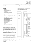
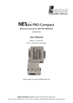
The 505-CP2572 Ethernet TCP/IP Communication Processor is a single
wide I/O module for SIMATIC 505 controllers (Figure 1-1). The 505-CP2572
provides connectivity to Ethernet local area networks and allows the PLC to
communicate with other network nodes using the Transmission Control
Protocol/ Internet Protocol (TCP/IP). Using the 505-CP2572, other devices
on the network can acquire data from the PLC, send data and programs to
the PLC, and exercise supervisory control over the PLC operation. The PLC
can also use the facilities of the 505-CP2572 to send messages to another
node on the network.
The 505-CP2572 attaches to all Ethernet media specified by IEEE 802.3
including 10Base5 (“thick” coaxial cable), 10Base2 (“thin” coaxial cable),
10BaseT (unshielded twisted pair cabling), FOIRL (fiberoptic cable) and
10BaseFL (fiberoptic cable). 10BaseT cabling can be attached directly to the
505-CP2572 via an RJ–45 connector. Other IEEE 802.3 media may be
connected to the AUI (Attachment Unit Interface) port via a user supplied
transceiver.
The 505-CP2572 also provides two serial ports that can be used to access
the PLC or to configure the module. Both serial ports can operate
concurrently.
The 505-CP2572 module itself requires no customer programming. All
configuration options can be set by module switches or written to module
EEPROM via a serially attached personal computer. Optionally, PLC logic
can be used to set module configuration and to control the operation of the
module.
Figure 1-1 505-CP2572 Module
1-2
Module Description
SIMATIC 505-CP2572 Ethernet TCP/IP User Manual
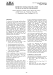
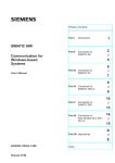
Ethernet Ports
The 505-CP2572 provides an IEEE 802.3 10BaseT port and an IEEE 802.3
AUI port. The 10BaseT port connects to Unshielded Twisted Pair (UTP)
cable using an RJ–45 connector. The 15 pin AUI connector is used to attach
a transceiver to the 505-CP2572. The transceiver, in turn, connects to the
desired Ethernet medium. Different transceivers are available for the
various 802.3 media. Thus, using a transceiver, the 505-CP2572 can connect
to coaxial, UTP, or fiber optic cable. See Figure 1-2.
ETHERNET
TCPAP
ACTIVE
10bT
PORT 1
PORT 2
AUI
10bT
AUI PWR
505–2572
AUI
AUI PWR
505–2572
Figure 1-2 505-CP2572 Ethernet Ports
Only one of the Ethernet ports is active at a time. The 505-CP2572
automatically selects the port to be used based on the signal received. If a
signal known as a link beat is detected on the 10BaseT port, then the
10BaseT port will be selected. If a link beat is not detected on the 10BaseT
port, then the AUI port will be selected.
The auto-selection feature allows you to run redundant cabling, if you wish.
If the link beat is lost on the primary 10BaseT port (typically indicating a
cable problem), the 505-CP2572 will automatically switch over to the AUI
port. When the link beat returns on the 10BaseT port, the module will
switch back to the 10baseT port. A bit in the Module Status Word can be
used by PLC logic to monitor which port is active. If bit 6 is on, then the
AUI port is selected; if the bit is off, then the 10BaseT port is selected. See
Appendix C for more information.
SIMATIC 505-CP2572 Ethernet TCP/IP User Manual
Module Description
1-3
Introduction (continued)
Ethernet transceivers are typically powered from the AUI port. The
505-CP2572 will supply the AUI port with power derived from the PLC
backplane. In certain configurations, however, you may wish to conserve
backplane power. For these circumstances, the 505-CP2572 provides a
connector that allows you to attach an external 12 VDC power supply. The
external power supply can then supply power to the AUI port. Refer to
Chapter 2 of this manual for installation details.
Serial Ports
The 505-CP2572 is equipped with two serial ports, (Figure 1-3). These ports
are provided for use with module configuration and diagnostic programs. In
addition, the ports may be used to access the local PLC. Devices that
communicate with the PLC using the Non Intelligent Terminal Protocol
(NITP) can access the PLC processor as if they were directly connected to
the PLC program port.
Optionally, NITP commands sent to a serial port can be redirected to
another node on the TCP/IP network. Using this feature, a SIMATIC
TISOFT program running on a PC connected to a 505-CP2572 serial port
can access another PLC on the network.
ETHERNET
TCPAP
ACTIVE
PORT 1
PORT 1
PORT 2
10bT
PORT 2
AUI
AUI PWR
505–2572
Figure 1-3 505-CP2572 Serial Ports
1-4
Module Description
SIMATIC 505-CP2572 Ethernet TCP/IP User Manual
Port 1 uses a male DB9 connector to provide a subset of RS–232C. Port 2
provides an RS–422 electrical interface using a female DB9 connector. Since
the pin configurations of the ports match those of SIMATIC 545 PLCs and
the PPX: 505-2571 Programming Port Expander module, standard cables
can be used. The ports may be configured via switches for baud rates of
1200, 2400, 9600, or 19,200. Optionally, PLC logic can be used to set the
communications parameters for the ports. Both ports can operate
concurrently with the Ethernet port; however, heavy serial port activity may
degrade network performance. See Appendix A for a diagram showing the
port pin configurations.
SIMATIC 505-CP2572 Ethernet TCP/IP User Manual
Module Description
1-5
Introduction (continued)
LED Indicators
The 505-CP2572 provides an array of LEDs that inform the user of the
module status and communications activity, (Figure 1-4). The functions of
the LEDs are described below.
ETHERNET
TCPAP
ACTIVE
ACTIVE
XMT
RCV
1
2
E
PORT 1
LB
ALM
POL
COL
PORT 2
10bT
AUI
AUI PWR
505–2572
Figure 1-4 LED Indicators
ACTIVE
Active Status Indicates the status of the module hardware. Solid
illumination indicates the module status is good. Slow blinking indicates the
module has detected a fault condition. Rapid blinking indicates that the
network parameters have not been set or are invalid.
XMT
Transmit There is one LED each for Serial Port 1, Serial Port 2, and
Ethernet which lights when data is transmitted on the applicable port.
RCV
Receive There is one LED each for Serial Port 1, Serial Port 2, and
Ethernet. These LEDs will light when a signal is received on the applicable
port. The Ethernet LED will flash when any network traffic is detected, not
just valid packets or packets addressed to the module.
LB
Link Beat Indicates that a link beat signal is being received on the
10BaseT port and that the 10BaseT port is selected. This LED should be lit
if 10BaseT is being used.
1-6
Module Description
SIMATIC 505-CP2572 Ethernet TCP/IP User Manual
AUI
Attachment Unit Interface Lights to indicate that the AUI port is
selected for Ethernet communications. If a link beat is not detected on the
10BaseT port, the AUI port will be automatically selected.
NOTE: The fact that the AUI LED is lit does not indicate that the attached
transceiver is operating properly.
POL
Polarity Reversed Lights when the polarity for the UTP cable connected
to the 10BaseT port has been reversed. This is a warning only, since the
505-CP2572 hardware will correct for reversed polarity.
COL
Collision Lights when a collision is detected. Some collisions are normal
when using Ethernet. Excessive collision activity may indicate faulty cable
termination, defective transceivers, or an overloaded network.
SIMATIC 505-CP2572 Ethernet TCP/IP User Manual
Module Description
1-7
1.2
Functional Overview
The 505-CP2572 can operate as both a PLC server and a PLC client. As a
PLC server, the 505-CP2572 responds to messages sent by another network
node. As a PLC client, the 505-CP2572 initiates messages on command from
the PLC.
PLC Server
Function
The 505-CP2572 can function as a server to clients who wish to access the
PLC. Figure 1-5 illustrates the typical message dialog between the client,
the 505-CP2572, and the PLC.
1) Command Message
4) Response Message
Client Node
2
5
7
2
2) PLC Command
3) PLC Response
P
L
C
Server PLC/505-CP2572
Figure 1-5 PLC Server Function
1-8
1.
The client node sends a command message to the 505-CP2572 via
TCP/IP. For example, the client may request that the 505-CP2572 read
and return 25 words of V-memory.
2.
Based the contents of a command message, the 505-CP2572 sends
commands and data to the PLC processor via the backplane. For
example, the 505-CP2572 would issue the applicable command to the
PLC to retrieve 25 words of V-memory.
3.
The PLC processor responds to the command via the backplane. In the
example, the PLC would return 25 V-memory words.
4.
After the PLC responds, the 505-CP2572 builds the appropriate
message and returns it to the client node. In this example, the
505-CP2572 would build a network message containing the 25 words of
data and send it to the client that requested it.
Module Description
SIMATIC 505-CP2572 Ethernet TCP/IP User Manual
Messages between the 505-CP2572 and the client node are encapsulated in
the TCP/IP protocol. The client device must create the TCP/IP packet
containing the command and must process responses from the 505-CP2572
returned via TCP/IP, (Figure 1-6). The client node may be a suitably
programmed computer or another 505-CP2572 on the network (see next
section). Please reference the 505-CP2572 Programming Reference Manual
for details regarding the message interface.
The 505-CP2572 will support multiple concurrent client/server sessions.
To operate the 505-CP2572 as a PLC server, no PLC logic changes are
required. However, you may wish to add PLC logic to set the network
parameters for the module (section 2.4 Using PLC Logic to Start the
Network Server).
SIMATIC 505-CP2572 Ethernet TCP/IP User Manual
Module Description
1-9
Functional Overview (continued)
PLC Client Function
The 505-CP2572 can also function as a PLC Client. As a PLC Client, the
505-CP2572 acts as an agent for the PLC; it sends messages to other nodes
and processes the responses under control of the PLC logic. Data in the PLC
program specifies the recipient and data contents of the message. PLC logic
sets a “trigger” bit to cause the 505-CP2572 to send the message.
2) Command Message
P
L
C
1) 2572 Command
4) 2572 Response
2
5
7
2
3) Response Message
Client PLC/505-CP2572
Server Node
Figure 1-6 PLC Client Function
In the example above:
1-10
1.
When the PLC detects a specified event, it sends a command to the
local 505-CP2572. For example, the command could be to read 5 words
from another node on the network.
2.
Based on the command, the 505-CP2572 then sends the applicable
command via TCP/IP to the specified network (server) node.
3.
The server node processes the command and returns a response via
TCP/IP. In the example, the server node would return a message
containing the specified words.
4.
The 505-CP2572 processes the network message and notifies the PLC
that the operation is complete. In the example, the 505-CP2572 would
place the words in a specified PLC memory location and signal
completion of the task.
Module Description
SIMATIC 505-CP2572 Ethernet TCP/IP User Manual
The 505-CP2572 can support multiple concurrent client sessions. The server
node shown in Figure 1-6 could be another 505-CP2572 or a computer
programmed to process the commands and send the appropriate responses.
Information describing the PLC logic required for client operation can be
found in Chapter 3 of this manual.
The 505-CP2572 can support multiple server sessions and multiple client
sessions concurrently. Therefore, networked PLCs can use the facilities of
the 505-CP2572 to participate in multi-session peer-to-peer
communications.
SIMATIC 505-CP2572 Ethernet TCP/IP User Manual
Module Description
1-11
1.3
TCP/IP Overview
The 505-CP2572 uses TCP/IP (Transmission Control Protocol/Internet
Protocol) to transport messages between the module and other nodes on the
network. TCP/IP is a suite of protocols which provide routing and delivery
services for messages between application programs running on different
processors (called hosts in TCP/IP terminology). You may select between
connectionless (packet based) or connection–oriented (stream based)
delivery services.
Connectionless
Delivery
Connectionless delivery services allow you to send a message to another
node without previously establishing a logical connection to the other node.
TCP/IP provides a format known as the User Datagram Protocol (UDP) for
sending and receiving connectionless messages. Connectionless delivery is
simple to implement and consumes a small amount of system resources.
However, delivery of UPD messages is not confirmed by the network
protocol. It is left to higher level protocols to acknowledge receipt of a
message. Since the Common ASCII Message Protocol (CAMP) used with the
505-CP2572 will acknowledge receipt of a command message, UDP is the
preferred protocol for most applications, such as process monitoring, which
obtain data from the PLC.
Connection
Oriented Delivery
With connection–oriented services, you must first establish a logical
connection (known as a virtual circuit) before network nodes can exchange
messages. TCP/IP uses the Transmission Control Protocol (TCP) to
implement connection–oriented services. TCP provides guaranteed delivery
and message flow control. If a message is not delivered correctly, the TCP
protocol will automatically retry. Since TCP is stream oriented, meaning the
application program sees a properly sequenced stream of data rather than
individual packets, it is often used for file transfer applications such as
program downloads. You may choose to use TCP for applications, such as
data logging, which require a specific piece of data be delivered in order.
Socket Interface
TCP/IP uses a standard structure known as a socket, for the application
program interface. The de facto socket standard is the Berkeley Socket,
named for the University of California at Berkeley, who originally
distributed TCP/IP. Originally, the Berkeley Sockets were used with only
the UNIX operating system. Today, software which implements the
Berkeley Socket standard is available for MS-DOS, IBM OS/2, and
Microsoft Windows. Microsoft, in conjunction with several TCP/IP
software providers, has established the Winsock standard to promote
interoperability among TCP/IP software using Windows.
Summary
The TCP/IP protocol is used to send and receive messages via the network.
It will function over the local Ethernet network or over Wide Area
Networks. TCP/IP supports both connectionless (UDP) and connection
oriented (TCP) services. UDP is usually sufficient for most applications
because the higher level application protocol (CAMP) incorporates an
acknowledgment to commands. TCP/IP network software for an IBM
compatible personal computer is readily available from a wide range of
sources.
1-12
Module Description
SIMATIC 505-CP2572 Ethernet TCP/IP User Manual
1.4
PLC Command Interface
Some 505-CP2572 functions require that you use PLC logic to control the
operation of the module. The 505-CP2572 provides a standard PLC logic
interface for sending messages and processing responses. The interface
consists of two parts.
•
Module WX/WY Words – used by PLC logic to control command
execution and monitor status.
•
Command Blocks – contiguous V-memory words used to store command
parameters.
Refer to Appendix D for a complete description of the WX/WY usage
including command timing diagrams.
505–CP2572 WX
and WY Words
The 505-CP2572 logs in as a Special Function module and is assigned two
WX words and six WY words. PLC logic uses the WY words to select the
Command Block and to trigger the command execution. The status of the
module and of command execution can be monitored via the WX words.
The words are used as shown in Table 1-1.
Table 1-1 505-CP2572 WX and WY Words
Word
Function
Description
WX1
Module Status
The high 8 bits contain module status bits. The lower 8 bits are a
counter that increments approximately once per second.
WX2
Command Status
Contains bits that the 505-CP2572 sets to indicate the status of command processing. There are four sets of 4 bits each. The four sets correspond to the four command slots and to the four sets of Command
Control bits in WY4.
WY3
Module Control
Contains bits which your PLC logic can use to control general module
functions (e.g. reset the module).
WY4
Command Control
Contains bits which PLC logic uses to control command processing by
the 505-CP2572. There are four sets of 4 bits. The four sets correspond
to the four command slots and to the four sets of Command Status bits
in WX2.
WY5
Command Slot 1
Contains the V-memory address of the Command Block used with the
first set of command and status bits.
WY6
Command Slot 2
Contains the V-memory address of the Command Block used with the
second set of command and status bits.
WY7
Command Slot 3
Contains the V-memory address of the Command Block used with the
third set of command and status bits.
WY8
Command Slot 4
Contains the V-memory address of the Command Block used with the
fourth set of command and status bits.
SIMATIC 505-CP2572 Ethernet TCP/IP User Manual
Module Description
1-13
Command Block
A Command Block is a contiguous group of V-memory words used to store
values which specify the specific module command that will be executed and
how the command will be processed. For example, the Command Block for a
Word Transfer – Read Remote command specifies:
•
The command number
•
The connection number
•
The beginning memory address in the remote PLC
•
The number of words to transfer
•
The beginning V-memory address in the local PLC where the answer
will be stored
The exact content of the Command Block will vary with the command being
issued. The Command Block is typically created in programming software
such as TISOFT, and stored permanently in PLC V-memory.
Figure 1-7 illustrates how the module WX/WY words and the command
blocks are used together. The 505-CP2572 writes values in the WX words,
the PLC writes values in the WY words. WX1 and WY3 contains bits allow
the PLC to monitor and control module global status. WY4 and WX2 contain
bits that allow the PLC to trigger commands and monitor command status.
The Command Slots contain the starting address of the Command Blocks.
To use the module command interface, your PLC logic typically loads a
Command Slot with the address of the desired command block. It then sets
a corresponding trigger bit in WY4 to cause the 505-CP2572 to execute the
command. Your logic then monitors the condition of the command status
bits in WX2 to determine whether the command completed successfully.
1-14
Module Description
SIMATIC 505-CP2572 Ethernet TCP/IP User Manual
Module WX/WY
WX1
MODULE STATUS WORD
WX2
COMMAND STATUS WORD
WY3
MODULE CONTROL WORD
WY4
COMMAND CONTROL WORD
WY5
COMMAND SLOT 1
WY6
COMMAND SLOT 2
WY7
COMMAND SLOT 3
WY8
COMMAND SLOT 4
ÎÎÎ
ÎÎÎ
ÎÎÎ
ÎÎÎ
ÎÎÎ
ÎÎÎ
ÎÎÎ
ÎÎÎ
ÎÎÎ
ÎÎÎ
ÎÎÎ
ÎÎÎ
Command Blocks
Figure 1-7 505-CP2572 PLC Interface
Typical Command
Operation
To execute a typical command, such as a Start Network Server, you first
create and store the Command Block in V-memory. The easiest way to
accomplish this is by using programming software such as TISOFT.
Alternately, you can use PLC logic to build the command block.
Once you have created the command block, you can use PLC logic to:
•
Load the address of the Command Block into a Command Slot.
•
Trigger the command using the set of bits in the Command Control
word that correspond to the Command Slot.
•
Monitor the status of the command using the set of bits in the
Command Status word that correspond to the Command Slot.
For example, assume you have logged in the module at WX1 and you want
to execute a Start Network Server command block located at V500.
•
Using TISOFT, you enter the command block data into PLC V-memory,
starting at V500.
•
Create PLC logic to write the value of 500 into WY5 (Command Slot 1).
•
Create the logic to control the Command Control bits associated with
Command Slot 1. In this case, the logic sets the Command Mode bit
(WY4.2) and the Command Trigger bit (WY4.3).
SIMATIC 505-CP2572 Ethernet TCP/IP User Manual
Module Description
1-15
1.5
Getting Started
Assigning an IP
Address
Before proceeding you must determine what IP address you will assign to
the module. If you are connecting to an existing network, your network
administrator will provide this information. If you plan on connecting your
network to the Internet you should contact the Internet Network
Information Center (NIC) for IP address assignment. If you are installing a
stand-alone network, you may choose any set of IP addresses as long as they
adhere to IP addressing conventions. See Appendix E of this manual for a
description of the IP Address numbering conventions.
Choosing and
Implementing a
Module Startup
Method
Before the 505-CP2572 will accept TCP/IP messages, the module Network
Server must be started. You can use PLC logic to assign the IP address and
to start the Network Server or you can have the module automatically start
the Network Server using an IP address stored in the 505-CP2572
EEPROM. See Chapter 2 for a description of these methods. If you choose to
use PLC logic, you will need to create a command block and incorporate a
few rungs of ladder into your program. See Section 2.4, Using PLC Logic to
Start the Network Server.
Setting Module
Switches
Module dipswitches configure the serial ports and select the startup
method. If you are using PLC logic to start the Network Server and wish to
use the standard serial port settings, ensure all dipswitches are in the off
position. See Section 2.2 Setting the 505-CP2572 Switches for a complete
description.
Installing the
Module in the PLC
I/O Base
The 505-CP2572 is a single wide module that installs in a standard 505
PLC rack. For best performance you should install the 505-CP2572 in the
first I/O slot of the local base. Chapter 2 describes unpacking and
installation of the module.
Logging the
Module in the PLC
I/O Configuration
When you initially install the module in the PLC I/O base, you must log the
module into the PLC I/O configuration. The 505-CP2572 logs in as 2 WX
and 6 WY words. See Checking PLC Login in Chapter 2.
NOTE: The module will not operate properly until it has been logged in.
1-16
Module Description
SIMATIC 505-CP2572 Ethernet TCP/IP User Manual
Connecting the
Module to the
Network
You can choose to connect the module directly to 10BaseT cabling or, via a
transceiver, to any IEEE 802.3 compliant media. See Section 2.6,
Connecting Cables.
Checking Out the
Module
You can use both the module indicators and commonly available software to
ensure the module is operating properly. Section 2.7, Module Checkout
describes this procedure. Chapter 4 also describes the module operation.
Using the Module
Assuming you have completed the above steps successfully, the 505-CP2572
is ready for use as a PLC Server. If you wish to implement PLC Client
functions, refer to Chapter 3 of this manual.
SIMATIC 505-CP2572 Ethernet TCP/IP User Manual
Module Description
1-17
Chapter 2
Installation
2.1
2.2
2.3
2.4
2.5
2.6
2.7
Installation Planning . . . . . . . . . . . . . . . . . . . . . . . . . . . . . . . . . . . . . . . . . . . . . . . . . . . . . . . . . . . .
2-2
Ethernet Media . . . . . . . . . . . . . . . . . . . . . . . . . . . . . . . . . . . . . . . . . . . . . . . . . . . . . . . . . . . . . . . . .
Serial Communications . . . . . . . . . . . . . . . . . . . . . . . . . . . . . . . . . . . . . . . . . . . . . . . . . . . . . . . . . .
Establishing Network Parameters . . . . . . . . . . . . . . . . . . . . . . . . . . . . . . . . . . . . . . . . . . . . . . . . .
Power Requirements . . . . . . . . . . . . . . . . . . . . . . . . . . . . . . . . . . . . . . . . . . . . . . . . . . . . . . . . . . . .
Unpacking the Module . . . . . . . . . . . . . . . . . . . . . . . . . . . . . . . . . . . . . . . . . . . . . . . . . . . . . . . . . .
2-2
2-2
2-2
2-3
2-4
Setting the 505-CP2572 Switches . . . . . . . . . . . . . . . . . . . . . . . . . . . . . . . . . . . . . . . . . . . . . . . . .
2-5
Serial Port Protocol . . . . . . . . . . . . . . . . . . . . . . . . . . . . . . . . . . . . . . . . . . . . . . . . . . . . . . . . . . . . . .
Serial Port Baud Rate . . . . . . . . . . . . . . . . . . . . . . . . . . . . . . . . . . . . . . . . . . . . . . . . . . . . . . . . . . . .
Port 1 Hardware Handshaking . . . . . . . . . . . . . . . . . . . . . . . . . . . . . . . . . . . . . . . . . . . . . . . . . . .
Network Startup Options . . . . . . . . . . . . . . . . . . . . . . . . . . . . . . . . . . . . . . . . . . . . . . . . . . . . . . . .
EEPROM Write Protect . . . . . . . . . . . . . . . . . . . . . . . . . . . . . . . . . . . . . . . . . . . . . . . . . . . . . . . . . . .
AUI Power Source Switch . . . . . . . . . . . . . . . . . . . . . . . . . . . . . . . . . . . . . . . . . . . . . . . . . . . . . . . .
2-6
2-7
2-7
2-8
2-9
2-9
Physical Installation . . . . . . . . . . . . . . . . . . . . . . . . . . . . . . . . . . . . . . . . . . . . . . . . . . . . . . . . . . . . .
2-10
Inserting the Module into the I/O Base . . . . . . . . . . . . . . . . . . . . . . . . . . . . . . . . . . . . . . . . . . .
Power Up . . . . . . . . . . . . . . . . . . . . . . . . . . . . . . . . . . . . . . . . . . . . . . . . . . . . . . . . . . . . . . . . . . . . . . .
Checking PLC Login . . . . . . . . . . . . . . . . . . . . . . . . . . . . . . . . . . . . . . . . . . . . . . . . . . . . . . . . . . . .
2-10
2-10
2-10
Using PLC Logic to Start the Network Server . . . . . . . . . . . . . . . . . . . . . . . . . . . . . . . . . . . . . . .
2-11
Ladder Logic Example . . . . . . . . . . . . . . . . . . . . . . . . . . . . . . . . . . . . . . . . . . . . . . . . . . . . . . . . . .
2-17
Automatically Starting the Network Server . . . . . . . . . . . . . . . . . . . . . . . . . . . . . . . . . . . . . . . .
2-18
Storing Network Parameters in EEPROM (PC Method) . . . . . . . . . . . . . . . . . . . . . . . . . . . . .
Selecting the AUTOSTART Startup Method . . . . . . . . . . . . . . . . . . . . . . . . . . . . . . . . . . . . . . . .
2-18
2-18
Connecting Cables . . . . . . . . . . . . . . . . . . . . . . . . . . . . . . . . . . . . . . . . . . . . . . . . . . . . . . . . . . . . .
2-19
Connecting to the 10BaseT Port . . . . . . . . . . . . . . . . . . . . . . . . . . . . . . . . . . . . . . . . . . . . . . . . .
Connecting to the AUI Port . . . . . . . . . . . . . . . . . . . . . . . . . . . . . . . . . . . . . . . . . . . . . . . . . . . . . .
Connecting to the Serial Ports . . . . . . . . . . . . . . . . . . . . . . . . . . . . . . . . . . . . . . . . . . . . . . . . . . .
2-19
2-20
2-21
Module Checkout . . . . . . . . . . . . . . . . . . . . . . . . . . . . . . . . . . . . . . . . . . . . . . . . . . . . . . . . . . . . . .
2-22
Power On . . . . . . . . . . . . . . . . . . . . . . . . . . . . . . . . . . . . . . . . . . . . . . . . . . . . . . . . . . . . . . . . . . . . . .
Ethernet (10BaseT Connector) . . . . . . . . . . . . . . . . . . . . . . . . . . . . . . . . . . . . . . . . . . . . . . . . . . .
Ethernet (AUI Connector) . . . . . . . . . . . . . . . . . . . . . . . . . . . . . . . . . . . . . . . . . . . . . . . . . . . . . . .
TCP/IP . . . . . . . . . . . . . . . . . . . . . . . . . . . . . . . . . . . . . . . . . . . . . . . . . . . . . . . . . . . . . . . . . . . . . . . . . .
Serial Ports . . . . . . . . . . . . . . . . . . . . . . . . . . . . . . . . . . . . . . . . . . . . . . . . . . . . . . . . . . . . . . . . . . . . . .
2-22
2-22
2-23
2-23
2-23
SIMATIC 505-CP2572 Ethernet TCP/IP User Manual
Installation
2-1
2.1
Installation Planning
Ethernet Media
The 505-CP2572 attaches directly to 10BaseT Media (Unshielded Twisted
Pair) via the RJ-45 connector. Should you choose another Ethernet medium,
you must obtain the appropriate transceiver to attach to the AUI port.
Ensure that the cables you use for Ethernet communications meet the IEEE
802.3 specifications and are appropriate for the area in which you are
operating.
NOTE: Check your cabling carefully. Faulty cables and/or connectors are the
leading cause of Ethernet communications problems.
Serial
Communications
If you wish to connect a device to a 505-CP2572 serial port, you should
make sure that the electrical interface and the communications parameters
for the serial port and the attached devices are compatible. In addition, you
should ensure that the correct message protocol has been selected.
Usually, you will use the DIP switches on the module to configure both the
serial port communications parameters and the port protocol. The DIP
switch settings are explained in Section 2.2.
The RS-232 port is configured as DTE. If the device requires hardware
handshaking for flow control, you should refer to the device documentation
for information on connecting the RTS, CTS, DCD, DTR, and DSR lines.
Establishing
Network
Parameters
Before the 505-CP2572 can communicate on a TCP/IP network, you must
establish the network parameters. These include an IP Address and Subnet
Mask for the module, a TCP/UDP port number for the PLC Network Server
function, and, if your network contains a router, the IP address of the
Default Router. See Appendix E for a complete description of TCP/IP
address nomenclature. You may also wish to refer to general publications
describing TCP/IP.
There are two methods for establishing the network parameters. One
method allows you to use the PLC program to set the IP address and other
network parameters. The second method allows you to load the information
directly from data stored in EEPROM on the 505-CP2572. You will need to
decide which method best suits your requirements.
If you choose to establish the network parameters using PLC logic, the
505-CP2572 will wait for the PLC to initiate network startup. Using a
special 505-CP2572 startup command, the PLC can set the network
parameters. When the module is reset for any reason (for example, during
module replacement), the PLC must restart the server software and re–load
the network parameters. The PLC logic to perform this function is described
in Section 2.4. Since the IP information is reloaded from the PLC and is not
stored in the module, the IP address remains with the PLC, even if the
505-CP2572 modules are swapped.
2-2
Installation
SIMATIC 505-CP2572 Ethernet TCP/IP User Manual
If you choose to obtain the network parameters from the EEPROM, the
module automatically initiates network startup based on the values in
EEPROM. No PLC logic is required to set the network parameters. Since
the IP address is not associated with the PLC program, you can download a
common program to multiple PLCs using the TCP/IP network. However, if
you arbitrarily swap 505-CP2572 modules between PLCs, the IP address
will move with the module. The effect of inadvertently swapping IP
addresses would probably be undesirable, since communications directed at
one PLC would actually be going to another PLC.
!
WARNING
If you choose to obtain the network parameters from EEPROM, be aware that
the IP address remains with the module. Therefore, arbitrarily swapping the
modules between PLCs could cause unpredictable behavior in the controller,
resulting in damage to equipment and/or injury to personnel.
Ensure your maintenance procedures safeguard against inadvertent module
swaps.
NOTE: Unless your application requirements dictate otherwise, it is
recommended that you allow the PLC to establish the network parameters.
NOTE: You will need to specify the IP address of the module, the logical port
number for the PLC server function, subnet mask, and the IP address of the
default router. You may need to obtain this information from your network
administrator before you begin.
Power
Requirements
The 505-CP2572 requires 6 watts of +5 VDC power, not including any power
supplied to a transceiver connected to the AUI port. If your media
configuration requires a transceiver and you wish to power it from the AUI
port, you should include the transceiver power requirement in your power
calculations. The formula for slot power calculation is: P = 6 + (TP x 1.15)
where P = total power slot requirement in watts and TP = transceiver power
requirement in watts. IEEE 802.3 specifications allow a transceiver to draw
a maximum of 500 ma at 12 VDC from the AUI port. In practice, many
transceivers draw considerably less. Should the total power required exceed
the backplane limitation, you may power the AUI from an external 12 VDC
power supply. The 505-CP2572 module provides a front panel connector for
attaching an external AUI power supply.
SIMATIC 505-CP2572 Ethernet TCP/IP User Manual
Installation
2-3
Installation Planning (continued)
NOTE: The AUI external power circuit contains a reverse protection diode
which may induce up to a 0.5 volt drop. Most transceivers can tolerate this
voltage drop. If your transceiver cannot, you should adjust your external
power supply to compensate.
!
CAUTION
If you are using a transceiver, make sure that you have included the power
requirements for the transceiver in your calculations. Failure to do so could
result in damage to equipment.
Before you insert the module into the I/O base, ensure that the PLC power
supply capacity is not exceeded.
Unpacking the
Module
Open the shipping carton and remove the special anti-static bag that
contains the module. After discharging any static build-up, remove the
module from the static bag. Do not discard the static bag. Always use this
bag for protection against static damage when the module is not inserted
into the I/O base.
!
CAUTION
The components on the 505-CP2572 module printed circuit card can be
damaged by static electricity discharge.
To prevent this damage, the module is shipped in a special anti-static bag.
Static control precautions should be followed when removing the module from
the bag, and when handling the printed circuit card during configuration.
2-4
Installation
SIMATIC 505-CP2572 Ethernet TCP/IP User Manual
2.2
Setting the 505-CP2572 Switches
Switches on the 505-CP2572 are used to select the following:
•
Serial Port Protocol
•
Serial Port Baud Rate
•
Hardware Handshaking for the RS–232 Port
•
Network Startup Option
•
EEPROM Write Protect
•
AUI Power
See Figure 2-1 for switch locations. Switchblock SW1 controls the settings
for Serial Port 1 (RS–232). Switchblock SW2 controls the settings for serial
port 2 (RS–422). Switchblock SW2 also sets the Network Startup Option
and the EEPROM protection.
Switch Block SW1
Switch Block SW2
AUI Power
Figure 2-1 Switch Locations for the 505-CP2572
NOTE: The switch settings are read by the module at startup only. If you
change the switch settings, you must reset the module by removing and
restoring power before the new settings will take effect.
SIMATIC 505-CP2572 Ethernet TCP/IP User Manual
Installation
2-5
Setting the 505-CP2572 Switches (continued)
Serial Port Protocol
Switches 6, 7, and 8 on each switch block are used to set the protocol used
by the port. Table 2-1 shows the serial port protocol options.
Table 2-1 505-CP2572 Serial Port Protocol Options
Protocol
Description
Use
CAMP/NITP
Supports both CAMP (Common
ASCII Message Protocol) and NITP
(Non–Intelligent Terminal
Protocol). The CAMP protocol
typically contains module specific
commands. TISOFT typically
generates NITP messages.
CAMP is used to perform special
functions such as writing network
parameters to EEPROM and
establishing a connection for
redirected serial data. NITP
typically contains PLC specific
commands.
NITP Only
Rejects message formats which are
not strictly NITP compliant.
Applications which require strict
adherence to the NITP
specifications
Loopback
Loopback generates a series of
ASCII characters which may be
directed back to the serial port via
a loopback connector.
Testing serial ports and cables.
PLC Select
Allows the PLC logic to select the
port protocol.
Custom port protocols using
loadable protocol managers.
8
7
6
5
4
3
Port
Protocol
Switch 6
Position
CAMP/NITP Server
NITP Only Server
Open
Switch 7
Position
Open
Switch 8
Position
Open
Open
Open
Closed
Loopback
Closed
Open
Open
PLC Select
Closed
Closed
Closed
2
1
Figure 2-2 Port Protocol Settings
NOTE: You should set the switches to use the CAMP/NITP protocol unless
you have a specific reason to do otherwise. Switch settings not shown are
reserved and should not be used.
2-6
Installation
SIMATIC 505-CP2572 Ethernet TCP/IP User Manual
Serial Port Baud
Rate
You can individually set the default baud rate settings for each serial port.
Refer to the diagram below for both Switchblock SW1 and Switchblock SW2.
See Figure 2-1 for switchblock locations.
8
7
6
5
4
3
Baud
Rate
Switch 1
Position
1200
Closed
Switch 2
Position
Closed
2400
Closed
Open
9600
Open
Open
19200
Open
Closed
2
1
Figure 2-3 Baud Rate Settings
Port 1 Hardware
Handshaking
Hardware handshaking for port 1 can be disabled or to enabled via a switch
on Switchblock SW1. If hardware handshaking is enabled, the attached
device must raise CTS before the 505-CP2572 will transmit data. See the
diagram below. The switches on some modules may be labeled Open and
Closed. The Closed position is equivalent to on.
8
7
6
5
Hardware
Handshaking
Switch 3
Position
Disabled
Open
Enabled
Closed
4
3
2
1
SW 1
Figure 2-4 Handshake Settings
NOTE: Unless the device you are attaching explicitly requires hardware
handshaking, you should leave hardware handshaking disabled.
SIMATIC 505-CP2572 Ethernet TCP/IP User Manual
Installation
2-7
Setting the 505-CP2572 Switches (continued)
Network Startup
Options
Switch 4 on Switchblock SW2 allows you to select how the 505-CP2572
starts up the PLC Network Server function. If you set the switch to PLC
Start, then the 505-CP2572 will wait for the PLC to issue a Start Network
Server command (see Section 2.4). The command block for this command
contains the network parameters (including IP address).
Switch 4
8
7
6
5
4
Startup Mode
Position
PLC Start
Open
Auto Start
Closed
3
2
1
SW2
Figure 2-5 Network Startup Options
If you set the switch to the Autostart position, then the 505-CP2572 will
automatically start the Network Server function, obtaining the network
data from EEPROM on the 505-CP2572. The switches on some modules
may be labeled Open and Closed. The Closed position is equivalent to on.
Before you can use the Autostart option you must store your network data
in EEPROM. You can use either PLC logic or a serially attached PC with a
Siemens supplied program to write the EEPROM. The data will remain
stored in EEPROM until changed. See page 2-18 for information on writing
EEPROM. The IP address stored in the EEPROM has purposely been set to
an invalid IP address at the factory.
Unless you have a significant reason to do otherwise, you should set the
switch to PLC Start and use PLC logic to start the Network Server. Then, if
you swap out a module, the PLC will automatically load the new module
with the correct IP address information and other network parameters. If
you choose the Autostart option, your maintenance procedures should guard
against inadvertent module swaps, since the IP address will move with the
module.
2-8
Installation
SIMATIC 505-CP2572 Ethernet TCP/IP User Manual
EEPROM Write
Protect
Switch 5 on switchblock SW2 protects the data in the EEPROM from being
overwritten. When Write Protect is on, the network parameters stored in
the EEPROM cannot be changed by the PLC program or by a PC attached
to a serial port. If a program attempts to write to the EEPROM when the
Write Protect switch is on, the 505-CP2572 will return an error code.
See Section 2.4 for procedures used to start the PLC network server using
PLC logic. See Section 2.5 and Section 2.6 for information on reading and
writing the module EEPROM.
Switch 5
8
7
6
5
4
EPROM Write
Protect
Position
Protect Off
Open
Protect On
Closed
3
2
1
SW2
Figure 2-6 EEPROM Write Protect Switch
The 505-CP2572 is shipped with all DIP switches in the Off (Open) position.
This corresponds to:
Baud Rate
Hardware Handshaking
Serial Port Protocol
Network Startup Mode
EEPROM Write Protect
AUI Power Source
Switch
9600
DISABLED
CAMP/NITP
PLC START
PROTECT OFF
The AUI power source switch is used to select whether power for the AUI
port is obtained from the PLC power supply or whether an external power
source is used. See Figure 2-1 for the location of the AUI Power Source
Switch. If you want to power the transceiver from the PLC, set the switch to
Internal. If you want to use an external power supply or have a transceiver
which supplies its own power, you must set the switch to the External
position.
NOTE: If the switch is set to the External position and you do not apply
external power, no power is applied to the AUI port. If you are having
problems with your transceiver, check the position of this switch.
SIMATIC 505-CP2572 Ethernet TCP/IP User Manual
Installation
2-9
2.3
Physical Installation
Inserting the
Module into the I/O
Base
Hold the top and bottom of the bezel and slide the module carefully into the
slot, pushing it all the way into the base. If you have inserted the module
correctly, you will feel a slight increase in resistance as the module mates
with the base backplane connector. Once the module is fully seated in the
slot, tighten the captive screws at the top and bottom to hold the module in
place. To remove the module from the I/O base, loosen the captive screws,
then remove the module. Take care not to damage the connector at the back
of the module when inserting or removing the module.
Power Up
Turn on the base power supply. Once the 505-CP2572 diagnostics have
completed and the network parameters are set, the ACTIVE indicator
should illuminate. If the indicator does not illuminate or exhibits a blinking
pattern, see Chapter 5 of this manual for troubleshooting information.
Checking PLC
Login
Next, log the module into the PLC I/O configuration. The 505-CP2572 logs
in as a special function module with 2 WX and 6 WY words. To configure the
PLC I/O refer to your SIMATIC TISOFT Programming Reference Manual.
In the example below, the 505-CP2572 module is installed into slot 1 on I/O
base 0 and will be logged in starting at address 1. Your configuration may
differ.
I/O MODULE DEFINITION FOR CHANNEL . . . . . 1
SLOT
01
02
.
.
.
15
16
I/O
ADDRESS
BASE . . . 00
NUMBER OF BIT AND WORD I/O
X
Y
WX
WY
SPECIAL
FUNCTION
. . . . . 0001 . . . . . . 00 . . . . 00 . . . . 02 . . . 06 . . . . . . . YES
. . . . . 0000 . . . . . . 00 . . . . 00 . . . . 00 . . . 00 . . . . . . . NO
. . . . . 0000 . . . . . . 00 . . . . 00 . . . . 00 . . . 00 . . . . . . . NO
. . . . . 0000 . . . . . . 00 . . . . 00 . . . . 00 . . . 00 . . . . . . . NO
Figure 2-7 Sample I/O Configuration Chart
After you read the I/O base, if the number of WX and WY words are the
same as those shown in the example above and Special function = YES,
then the PLC can recognize the module. Change the address as required by
your application and save the result. If the line is blank or erroneous,
re-check the module to ensure that it is firmly seated in the I/O base slot.
Generate the PLC I/O configuration chart again by reading the I/O base. If
the problem persists, contact your distributor.
NOTE: If you do not log the module in correctly, it will not function properly.
2-10
Installation
SIMATIC 505-CP2572 Ethernet TCP/IP User Manual
2.4
Using PLC Logic to Start the Network Server
The Start Network Server command is used when you want to establish the
network parameters using PLC logic. When you use PLC logic to set the
network parameters, you can ensure that the IP address is directly
associated with the PLC and not the module.
NOTE: Before you can use PLC logic to start up the PLC network server
function, the Network Startup Option switch must be set to PLC Start.
See Figure 2-5.
The 505-CP2572 uses the PLC V-memory to store command information and
the module WX/WY words to control execution of the commands. If you are
not familiar with this interface, please refer to Appendix D of this manual.
Also see the ladder logic example (Figure 2-9).
NOTE: If you store the network parameters in EEPROM and use the module
Autostart switch option, you are not required to execute this command.
The network data parameters are set by the PLC when the Start Network
Server command block is executed. This block is shown in Table 2-2. In the
table, a bold entry is a required value. A non-bold entry is a recommended
value which you should use unless you have reason to do otherwise. Values
for the command block entries are shown in both hexadecimal and decimal
(integer) format. If you are using TISOFT, you can configure a chart to
display the values either way.
This command should be executed only when the 505-CP2572 has set the
Network Configuration Required bit (Net Cfg). The Net Cfg bit is set shortly
after power is first applied to the module or after the module is reset for any
reason. It remains on until the network parameters have been set. If you
have chosen the PLC Start option for network startup, you must
successfully complete this command before the 505-CP2572 will respond to
any other network commands. See the ladder logic example (Figure 2-9).
NOTE: When you trigger the Start Network Server command, if the
command block contains invalid data, the 505-CP2572 will return an error
code and then halt. To recover, you must correct the command block entry
and reset the module by cycling power.
SIMATIC 505-CP2572 Ethernet TCP/IP User Manual
Installation
2-11
Using PLC Logic to Start the Network Server (continued)
Table 2-2 Startup Network Command Block
Offset
Description
Hex value
Decimal
Value
0
Command Error Word
0000
0
1
Command (Start Network Server)
0004
4
2
Connection Number (19291 – 19299)
4B62
19298
3
Protocol Manager Number
0023
35
4
Startup Option Bits (see description below)
0000
0
5
TCP Keep Alive Interval in seconds (0=default to 60
seconds)
0000
0
6
IP Address of this Module (High 16 bits)
7
IP Address of this Module (Low 16 bits)
8
TCP / UDP Port Number
05E1
1505
9
IP Address of Default Router (High 16 bits)
10
IP Address of Default Router (Low 16 bits)
11
Max Number of TCP Connections (0=default)
0000
0
12
Subnet Mask (High 16 bits)
0000
0
13
Subnet Mask (Low 16 bits)
0000
0
14
Unused – reserved for future use (Set to 0)
0000
0
15
Unused – reserved for future use (Set to 0)
0000
0
Offset 0 Error Word – Set to 0 so that any previous error code is cleared.
Offset 1 Command Code – The Command for Start Network Server is 4.
Offset 2 Connection Number – You should set this to number in the range
of 19291 to 19299 to prevent inadvertent conflict with any client
connections you may create. The value of 19298 is used in the
examples.
Offset 3 Protocol Manager Number – Protocol Managers control the
operation of the serial and network ports. Protocol Manager 35 (23 hex)
selects the PLC Network Server.
Offset 4 Startup Option Bits – These bits allow you to configure certain
options for the PLC server. The bits are used as follows:
2-12
Installation
SIMATIC 505-CP2572 Ethernet TCP/IP User Manual
Table 2-3 Startup Option Bits
Bit 1
TCP Server Disable
0 = TCP Enabled
1 = TCP Disabled
Bit 2
UDP Server Disable
0 = UDP Enabled
1 = UDP Disabled
Bit 3
Echo Server Disable
0 = Server Enabled
1 = Server Disabled
Bit 4–16
Reserved
(set to 0)
TCP Server Disable Setting this bit to 1 will disable TCP connections to
the PLC server. The 505-CP2572 will reject attempts by a remote client to
connect via TCP to the server. However, you can still initiate a client TCP
connection from this PLC. A setting of 0 (TCP Enabled) is the normal mode.
UDP Server Disable Setting this bit to 1 will disable UDP
(connectionless) protocol for the server. The 505-CP2572 will reject all UDP
datagrams sent to the server. However, you can still initiate a client UDP
connection from this PLC. A setting of 0 (UDP Enabled) is the normal mode.
Echo Server Disable Setting this bit to 1 will disable the TCP and UDP
echo servers (Port 7). TCP connection attempts and UDP datagrams
directed to port 7 will be rejected by the 505-CP2572. A setting of 0 (Echo
Server Enabled) is the normal mode.
You might choose to disable TCP for the server if you need additional
process slots for creating client network connections. Disabling TCP frees
two process slots which allows you to create two additional network
connections. When you disable TCP, the server will still process UDP
messages.
You might choose to disable UPD if you want to support only
connection-oriented conversations. This option can provide a means to limit
the transaction load on the PLC server, since you can also control the
number of TCP connections allowed (see offset 11). You may also choose to
disable UDP if you need an additional process slot for a TCP/IP socket.
When you disable UDP, the 505-CP2572 is able to support one additional
TCP server connection or PLC Client network connection.
You might choose to disable both TCP and UDP if you are using the
505-CP2572 in client mode only. Note that you must have at least one
enabled 505-CP2572 server or computer host server somewhere on the
network to respond to your messages. This option frees up three additional
process slots.
SIMATIC 505-CP2572 Ethernet TCP/IP User Manual
Installation
2-13
Using PLC Logic to Start the Network Server (continued)
The Echo Servers (TCP and UDP) provide a handy diagnostic tool for
checking out TCP/IP communications at a level higher than Ping. You may
wish to disable the Echo Servers if you need to obtain more process slots for
the 505-CP2572 PLC server. Disabling the Echo servers frees up two
process slots.
Unless you have a specific reason to do otherwise, use the defaults.
NOTE: You cannot disable TCP, UDP, and the ECHO servers simultaneously.
At least one must be enabled in order to start the network server.
Offset 5 TCP Keep Alive Interval – This value specifies the amount of
elapsed time (in seconds) without any messages from the client
application before the 505-CP2572 will automatically close a server
TCP socket. If the value is set to 0, then the 505-CP2572 will explicitly
default to 60 seconds. A value of 65000 or greater will disable keep
alive.
Offset 6–7 IP Address – Offset 6 should contain the high 16 bits of the
module IP address. Offset 7 should contain the low 16 bits of the IP
address. An IP address of 0.0.0.0 (0000 0000 hex) or greater than
223.255.255.255 (DFFF FFFF hex) is will return an error.
Offset 8 TCP/UDP Port – This will be the port ID used to connect to the
505-CP2572 PLC Server application. Documentation examples assume
that this will be set to 1505 decimal. You should use this value unless
you have a reason to do otherwise. Note that port numbers 1023 and
below are reserved by the IANA (Internet Assigned Numbers
Authority) for “well known” ports. Other values may have been
reserved by your network administrator. Port 7 is automatically
assigned as an echo server in compliance with RFC 1340. A port
number of 0 is invalid.
Offset 9–10 IP Address of Default Router – This identifies the address of
the router to which unknown IP addresses will be directed. Offset 8
contains the high 16 bits of the address and Offset 9 contains the low
16 bits. An address greater than 223.255.255.255 (DFFF FFFF hex)
will return an error. If you do not have a router on your network, set
this to 0.0.0.0 (0000 0000 hex).
2-14
Installation
SIMATIC 505-CP2572 Ethernet TCP/IP User Manual
Offset 11 Maximum Number of TCP Connections – This specifies the
maximum number of concurrent TCP connections to the PLC server
that will be allowed. Once the maximum number has been attained, the
505-CP2572 will reject further attempts to connect until a connection is
relinquished. Once a connection is properly closed, the slot is available
for another connection. If you set the value in this word to 0, then the
505-CP2572 will use the default module value (8). You may set this to a
number less than 8 to limit access. You may also increase the number
beyond 8 as follows:
•
Increase the number by 1 for each unused Client connection (Up to 8).
•
Increase by 2 if you disable the Echo Servers (see offset 4).
•
Increase by 1 if you disable UPD Server (see offset 4).
Offset 12–13 Subnet Mask – Specifies the subnet mask assigned to this
network. Offset 12 contains the high 16 bits of the mask and Offset 13
contains the low 16 bits. If offset 12 and 13 contain a value of 0, then
the subnet mask will default to the standard for the IP address class. A
subnet mask must contain all 1’s in the network portion of the IP
address and must allow at least 2 bits of host address. In addition, the
subnet mask cannot be set so that the derived host address is 0 or a
broadcast address (all bits set to 1). See Appendix D.
NOTE: All computers on a physical network must use the same Subnet mask
and Network ID; otherwise, addressing and routing problems can occur.
Host ID’s on the same network must be unique.
NOTE: If you set the startup option to PLC Start, you must successfully
complete this command before any other network functions will execute. If
you set the startup option to Autostart and the EEPROM contains valid
network parameters, you are not required to execute this command.
NOTE: You must set the module startup option to Autostart and reset the
module before any EEPROM changes will take effect.
SIMATIC 505-CP2572 Ethernet TCP/IP User Manual
Installation
2-15
Using PLC Logic to Start the Network Server (continued)
When you are setting up the various IP addresses and subnet mask, you
should set up TISOFT to display the words in hexadecimal. Then you can
enter each byte of the dotted notation individually. For example, if the IP
address were 198.35.34.10, you could enter the first word as hex C623
where the high byte (C6) is the hex equivalent of decimal 198 and the low
byte (23) is the hex equivalent of decimal 35. Similarly, you would enter the
second word as hex 220A. See Figure 2-8.
Hex Value
Dotted Decimal
Hex Value
C6 23
C623
Offset 6
220A
Offset 7
198.35.34.10
22 0A
Figure 2-8 Example of an IP Address in Hexadecimal
2-16
Installation
SIMATIC 505-CP2572 Ethernet TCP/IP User Manual
Ladder Logic
Example
Figure 2-9 illustrates the ladder logic which executes the Start Network
Server command block. This example assumes that the command block is
located in V-memory starting at V500 and that command slot 1 is used for
the command.
C100
C100
LDC
WY5
500
C100
WX1.3
WX2.3
WY4.2
Set the command
to Coupled Mode
WY4.3
WY4.3
Sets the Command
Trigger
Figure 2-9 PLC Logic Example
Rung 1 loads the location of the Command Block (V500) into Command Slot
1 (WY5). Once the control relay is on, it seals off the command. The load
command will be bypassed on subsequent scans.
Rung 2 sets the Command Trigger (WY4.3) and Command Mode (WY4.2)
when the Net Cfg bit (WX1.3) is on and the Command Busy bit (WX2.3) is
off. When the logic sees the 505-CP2572 raise Command Busy (WX2.3), it
lowers the Command Mode (WX4.2) and Command Trigger (WX4.3),
completing the coupled mode cycle.
The Net Cfg bit will be raised by the 505-CP2572 at any time the network
configuration parameters are not set. Therefore this logic will re-execute the
Start Network Server command, if the 505-CP2572 is reset for any reason.
NOTE: Do not use retentive relays in this application.
SIMATIC 505-CP2572 Ethernet TCP/IP User Manual
Installation
2-17
2.5
Automatically Starting the Network Server
Storing Network
Parameters in
EEPROM
(PC Method)
Before you can automatically start the Network Server, the network
parameters, including the module IP address, must be stored in EEPROM
on the 505-CP2572. You can accomplish this task using an IBM compatible
PC and a utility program.
1.
Attach the PC to Port 1 (RS–232) using a serial cable wired for RS–232.
See Appendix A for a typical cable example. The cable that you use
with TISOFT should work properly.
NOTE: Make sure that the communications parameters set for the
505-CP2572 match those of the PC and that the CAMP/NITP protocol is
selected (see section 2.2).
2.
Place the diskette labeled 505-CP2572 Utilities in a 3.5” diskette drive.
3.
Run the IPSET program from the diskette.
4.
Follow the instructions on the screen for establishing the network
parameters.
NOTE: Ensure that the EEPROM Write protect switch is off (See Figure 2-6).
You can also use the IPSET program to read the network parameters
contained in the EEPROM. Complete instructions for using the IPSET
program can be found in the IPSET.TXT file located on the 505-CP2572
Utilities diskette.
Selecting the
AUTOSTART Startup
Method
Once you have completed setting the IP address, you should power down the
module and ensure that Network Startup Option Switch is set to Autostart.
You may also wish to set the EEPROM Write Protect switch to On. The new
IP address will take effect when power is re-applied to the module.
NOTE: If you do not set the Network Startup Option switch to the Autostart
position and there is no PLC logic to set the network parameters, the IP
address will not be set. The module Active LED will continue to blink.
2-18
Installation
SIMATIC 505-CP2572 Ethernet TCP/IP User Manual
2.6
Connecting Cables
Connecting to the
10BaseT Port
Insert the 8 pin (RJ-45) plug on your unshielded twisted pair cable into the
RJ-45 jack on the 505-CP2572. Push the plug into the jack until the plug
clicks into place. Attach the other end of the cable to a hub. See Figure 2-10.
When a link beat is detected on the 10BaseT port, the 505-CP2572
automatically selects this port. When you attach a cable that is connected to
an active hub, the Link Beat (LB) LED should light.
Figure 2-10 10BaseT Connection
SIMATIC 505-CP2572 Ethernet TCP/IP User Manual
Installation
2-19
Connecting Cables (continued)
Connecting to the
AUI Port
The AUI port is equipped with a standard locking connector. To attach a
transceiver or AUI cable to the AUI connector follow the steps below. See
Figure 2-11.
1.
Slide the AUI retaining ring to the full down position.
2.
Plug the transceiver or cable into the 505-CP2572 AUI port.
3.
Using the blade of a small screwdriver, slide the AUI retaining ring to
the full up position.
4.
Ensure that the transceiver or cable has been locked in place.
5.
Attach the network cable to the transceiver.
AUI Retainer
AUI Connector
AUI Cable
Figure 2-11 AUI Connection
The clearance between some transceivers and the front panel of the
505-CP2572 can make it difficult to slide the retaining ring to the locked
position. In this case you may wish to connect the cable or transceiver with
the module removed from the backplane. With the module removed, the
retaining ring can be accessed from the rear of the front panel.
NOTE: The AUI Power switch must be set to Internal to obtain power for the
transceiver from the PLC power supply.
2-20
Installation
SIMATIC 505-CP2572 Ethernet TCP/IP User Manual
Connecting to the
Serial Ports
Devices are connected to the serial ports of the 505-CP2572 via
communications cables. Port 1 provides a subset of the RS–232C electrical
interface. Cables for the RS–232 ports should be no longer than 50 feet. Port
2 provides an RS-422 electrical interface. RS–422 cables may be up to 4000
feet in length.
The serial port connectors on the 505-CP2572 have been designed to accept
commonly used serial cables. The pin-outs on the RS–232 port and the
RS–422 port match those found on the 545 PLC. In addition, the RS–232
connector matches those found on IBM PC/AT machines. Should you choose
to construct your own custom cables, please refer to Appendix A for
connector pin-out descriptions.
SIMATIC 505-CP2572 Ethernet TCP/IP User Manual
Installation
2-21
2.7
Module Checkout
Power On
When power is applied to the 505-CP2572, the ACTIVE LED should light
after about one or two seconds. If the ACTIVE LED fails to light and you are
certain that power is applied, then the module hardware is defective. If the
ACTIVE LED periodically cycles off and on every two seconds, it indicates
that the module diagnostics have detected a hardware problem. Refer to
Chapter 5 Troubleshooting before proceeding.
If the LED blinks rapidly (about once per second), it indicates that the
network parameters (including IP address) for the module are not set. Refer
to Section 2.4 and Section 2.5 for information on setting the parameters.
NOTE: If you chose to obtain the IP address information from the PLC, the
PLC switch must be set to the RUN position before the program can
transfer the information to the 505-CP2572.
Ethernet (10BaseT
Connector)
When you attach to the network using the 10BaseT connector the following
should occur:
1.
The AUI LED should extinguish and the LB (Link Beat) LED should
illuminate. This indicates that a valid link beat is being obtained from
the hub and that the 10BaseT port has been selected by the
505-CP2572.
2.
If you are attached to an active network, you should see the Ethernet
RCV (receive) LED flicker, indicating network signals are being
received.
If the above conditions are not met, refer to Chapter 5.
2-22
Installation
SIMATIC 505-CP2572 Ethernet TCP/IP User Manual
Ethernet (AUI
Connector)
When you are using an Ethernet transceiver attached to the AUI port you
should experience the following:
1.
The AUI LED should light and the LB LED should not be lit.
This indicates that the AUI port has been selected by the 505-CP2572.
2.
If you are attached to an active network, you should see the Ethernet
RCV (receive) LED flicker, indicating network signals are being
received.
If the above conditions are not met, refer to Chapter 5 of this manual.
NOTE: If you are connected to both the AUI port and the 10BaseT port, the
505-CP2572 will automatically select the 10BaseT port if a Link Beat is
received on the port. If no Link Beat signal is received on the 10BaseT port,
the 505-CP2572 will automatically select the AUI port.
TCP/IP
If functioning properly, the 505-CP2572 will respond to an ICMP Echo
Request message known as a ping. When you ping the 505-CP2572 from a
network node, it should reply. If the module does not reply, make sure that
you have set the module IP address properly. When converting from dotted
decimal format to dotted hexadecimal format, it is easy to make a mistake.
Serial Ports
If you wish to check out the serial ports, you should attach an operator
interface device which supports NITP to one of the serial ports. Then send a
command to the 505-CP2572 (such as a Read V-Memory).
You should observe the following:
1.
The RCV (receive) LED for the port should blink when the command is
sent.
2.
Within a second (approximately), the XMT (transmit) LED for the port
should blink, indicating a response has been sent from the 505-CP2572.
3.
The attached device should display the appropriate response.
NOTE: Serial ports on the 505-CP2572 identify themselves as I/O slots not as
PLC program ports. Devices that rely on the serial port to be explicitly
identified as a program port may fail to communicate with the 505-CP2572.
SIMATIC 505-CP2572 Ethernet TCP/IP User Manual
Installation
2-23
Chapter 3
Client Commands
3.1
Overview of Client Commands . . . . . . . . . . . . . . . . . . . . . . . . . . . . . . . . . . . . . . . . . . . . . . . . . .
3-2
Create Socket Command . . . . . . . . . . . . . . . . . . . . . . . . . . . . . . . . . . . . . . . . . . . . . . . . . . . . . . .
Close Socket Command . . . . . . . . . . . . . . . . . . . . . . . . . . . . . . . . . . . . . . . . . . . . . . . . . . . . . . . .
Memory Transfer Commands . . . . . . . . . . . . . . . . . . . . . . . . . . . . . . . . . . . . . . . . . . . . . . . . . . . .
Word Transfer – Write Remote . . . . . . . . . . . . . . . . . . . . . . . . . . . . . . . . . . . . . . . . . . . . . . . . . . . .
Word Transfer – Read Remote . . . . . . . . . . . . . . . . . . . . . . . . . . . . . . . . . . . . . . . . . . . . . . . . . . .
Word Transfer – Memory Exchange (Firmware Version 4.7 and above) . . . . . . . . . . . . .
Application Example – Start Network Server Command Block . . . . . . . . . . . . . . . . . . . . .
Create Socket Command Block . . . . . . . . . . . . . . . . . . . . . . . . . . . . . . . . . . . . . . . . . . . . . . . . .
Word Transfer Command Block . . . . . . . . . . . . . . . . . . . . . . . . . . . . . . . . . . . . . . . . . . . . . . . . . .
PLC Ladder Logic Example . . . . . . . . . . . . . . . . . . . . . . . . . . . . . . . . . . . . . . . . . . . . . . . . . . . . . .
3-2
3-5
3-6
3-6
3-8
3-10
3-13
3-14
3-15
3-15
SIMATIC 505-CP2572 Ethernet TCP/IP User Manual
Client Commands
3-1
3.1
Overview of Client Commands
The client commands are used when you wish to use PLC logic to initiate
communications. This function may be used to transfer data among PLCs
using the 505-CP2572 with each PLC. You may also find it useful for
sending alarm data to MMI software which supports unsolicited reads via
TCP/IP. Using the client mode to report alarms avoids the requirement to
continuously poll for alarm data, thus conserving processor and network
bandwidth.
NOTE: If you are using the 505-CP2572 in Server mode only, you can skip
the remainder of this section.
Create Socket
Command
The Create Socket command provides a means for your PLC logic to refer to
another network node when sending messages. You must complete the
Create Socket command before you can send messages to another node on
the network.
The Create Socket command creates a local TCP/IP socket and associates it
with the remote socket specified by the values for IP address and port in the
command block. If TCP is specified, an actual logical connection to the
remote node is attempted. If the connection cannot be established, the
505-CP2572 will return an error code to the PLC. If UDP is specified, the
505-CP2572 saves the address and port number as the default remote
socket, but no connection attempt is made. Once the Create Socket
command completes successfully, your logic can use the Connection Number
to refer to the remote socket. You can establish up to eight concurrent
connections.
NOTE: If you choose UDP, the 505-CP2572 will wait until the first message
is sent to determine the physical address of the remote node. As a result,
the first attempt to complete a memory transfer to a newly referenced
network node may time out while address resolution is being completed.
Consequently, your PLC logic should always retry UDP commands.
3-2
Client Commands
SIMATIC 505-CP2572 Ethernet TCP/IP User Manual
Offset
Description
Hex
Value
Decimal
Value
0
Error Word
0000
0
1
Command Code (Create Socket)
0003
03
2
Connection Number (19221 – 19228)
3
Protocol Manager Number
0024
36
4
Startup Option Bits
0000
0
5
Type of Service (1 = TCP, 2 = UDP)
6
IP Address of Remote Device – High 16 bits
7
IP Address of Remote Device – Low 16 bits
8
Unused (Set to 0)
0000
0
9
Remote Device – TCP/UDP Port Number
10 – 15
Unused (Set to 0)
0000
0
Offset 0
cleared.
Error Word – Set to 0 so that any previous error codes are
Offset 1 Command Code – The Command Code of the Create Socket
command is 03.
Offset 2 Connection Number – Network Client connection numbers may
range from 19221 through 19228. Any connection number within the valid
range can be assigned, as long as the number is unique. Connections can be
closed and re–used, if desired. To help keep track of the connection
numbers, you may wish to assign connection numbers sequentially.
Offset 3 Protocol Manager Number – Protocol Managers control the
operation of the serial and network ports. The Protocol Manager Number for
the CAMP Client protocol manager is decimal 36 (hex 24).
Offset 4
Startup Option Bits – (firmware version 5.0 or greater).
Bits 1 – 14
Bit 15 – IP Address
Location
Bit 16 – Client priority
Not Used
0 = Use IP Address in
Create Socket Command
Block
0 = Normal priority
1 = High priority
1 = Use IP Address in
Memory Transfer
Command Block (UDP
only)
SIMATIC 505-CP2572 Ethernet TCP/IP User Manual
Client Commands
3-3
Overview of Client Commands (continued)
When bit 15 is set to 1 (Offset 4 = 0x0002) and the UDP protocol is selected
(in Offset 5), the Command Blocks used for Memory Transfer (Read Remote,
Write Remote, and Memory Exchange) will specify the IP Address and Port
Number for the remote device. See Section 3.4. Memory Transfer
Commands. This feature allows you to use a single socket to communicate
with different remote devices. When bit 15 is set to 0, the IP address and
port number entered in this Create Socket command block will be used. The
TCP protocol, since it is connection–oriented, will always use the IP address
and port number in this Create Socket command block. If you select TCP
and set bit 15 to 1, the 505-CP2572 will return an error.
Bit 16 controls the priority given to this client application. When bit 16 is
set to 0 (offset 4 = 0x0000), the client application will execute with a normal
priority. When bit 16 is set to 1 (offset 4 = 0x0001), the client application
will execute with a high priority. High priority client applications will be
scheduled before all server applications and all client applications operating
at normal priority. One use of the high priority setting could be sending
critical alarm data. You should use normal priority unless your application
definitely requires high priority.
NOTE: Even if bit 1 is set, you must have a valid IP address in the Create
Socket command to avoid a command error.
NOTE: Use the high priority setting with care. You can significantly degrade
the 505-CP2572 network server performance by setting several client
applications to high priority then rapidly and continuously triggering data
transfer commands for the client applications.
Offset 5 Type of Service – Selects between UDP (conectionless) or TCP
(connection–oriented) service. Using UDP, the local socket is created but no
connection is established with the target node. Using TCP, a virtual circuit
connection is established with the other node. If the TCP connection cannot
be established, the 505-CP2572 will indicate an error.
NOTE: If TCP is selected and the connection with the target node (remote
host) is lost, the 505-CP2572 will report a socket connection error code (such
as 240A – Socket not Connected) the next time you attempt to read/write
data. The connection may be lost due to problem with the remote host or the
network. After the error is acknowledged, the 505-CP2572 will complete
error recovery by automatically closing the socket. A subsequent
attempt to read/write data will result in a 00A6 (connection not active)
error. See Appendix B for error code listings. Your logic should re-execute
the Create Socket command if the connection is not active.
3-4
Client Commands
SIMATIC 505-CP2572 Ethernet TCP/IP User Manual
Offset 6–7 IPAddress – If the IP Address Selection option bit in Offset 4 is
set to 0, these words specify the IP address of the destination node. Since
the IP address consists of 32 bits, the address is contained in two 16 bit
words. An IP address of 0.0.0.0 (0000 0000 hex) or greater than
223.255.255.255 (DFFF FFFF hex) will return an error.
Offset 8 Unused – This word is not used when creating a TCP/IP socket.
It should be set to 0.
Offset 9 TCP/UDP port number – If the IP Address Selection option bit
in Offset 4 is set to 0, this word specifies the TCP/UDP port number of the
remote node. If you are accessing another 505-CP2572, you will typically set
this value to 1505 (the recommended value for the 505-CP2572 PLC server).
If you are using UDP and bit 15 of offset 4 is set to 1, then this address
becomes the default port number.
Offset 10–15 Unused – These words are unused and should be set to 0.
Close Socket
Command
The following command block will close a connection to a TCP/IP socket.
Once the connection has been successfully closed, you can re-use the
connection number in a subsequent Create Socket command block.
Offset
Description
Hex
Value
Decimal
Value
0
Error Word
0000
0
1
Command Code (Close Connection)
0002
02
2
Connection Number (19221 – 19228)
3 – 15
Unused (Set to 0)
0000
0
Offset 0
cleared.
Error Word – Set to 0 so that any previous error codes are
Offset 1 Command Code – The Command Code of the Close Connection
command is 02.
Offset 2 Connection Number – You can specify any connection number
that has been previously established in a Create Socket command block.
Offset 3–15 Unused – These words are unused by this command and
should be set to 0.
SIMATIC 505-CP2572 Ethernet TCP/IP User Manual
Client Commands
3-5
Overview of Client Commands (continued)
Memory Transfer
Commands
Memory Transfer commands are designed to provide a device independent
method of transferring data words. For SIMATIC 505 controllers, the
memory transfer commands provide a simple way to transfer V-memory
between the local PLC and another PLC (or suitably programmed computer)
on the network. These commands access only the first 64K bytes of
V-memory. Before using the Memory Transfer commands you must have
successfully completed a Create Socket command.
Word Transfer –
Write Remote
This function reads the contents of a designated area of V-memory in the
local PLC and writes the values in a specified area of memory in another
device. You can specify the starting memory addresses on both the local and
remote PLCs and the number of words to be transferred (up to 256 words).
Based on the specification, the 505-CP2572 reads the local V-memory and
sends a message to the network recipient associated with the Connection
Number. When the response is returned from the remote PLC, the
505-CP2572 verifies that the message was properly processed. If not, the
505-CP2572 places an error code in the command block and raises the
applicable error bit. The following command block is used for the Write
Remote Memory command.
Offset
3-6
Client Commands
Description
Hex
Value
Decimal
Value
0
Error Word
0000
0
1
Command Code (Write Remote Memory)
0201
513
2
Connection Number (19221 – 19228)
3
Source: Starting V-memory Address in this PLC
4
Number of Words to Transfer (1 – 256)
5
Destination: Starting V-memory Address in
Remote PLC
6
Command Timeout in seconds (0 = Use Default)
0000
0
7–9
Unused (Set to 0)
0000
0
10
IP Address of Remote Device – High 16 bits
(UDP Only: IP Address Location bit in the Create
Socket command must be set to 1)
11
IP Address of Remote Device – Low 16 bits
(UDP Only: IP Address Location bit in the Create
Socket command must be set to 1).
12
UDP Port Number of Remote Device
(UDP Only: IP Address Location bit must be set
to 1)
13 – 15
Unused (Set to 0)
0000
0
SIMATIC 505-CP2572 Ethernet TCP/IP User Manual
Offset 0
cleared.
Error Word – Set to 0 so that any previous error codes are
Offset 1 Command Code – The Command Code is 513 decimal (or 0201
hexadecimal).
Offset 2 Connection Number – You can specify any connection number
that has been previously established in a Create Socket command block.
Offset 3 Source – The starting address of V-memory which contains the
values you want to transfer. The address is 1 relative.
Offset 4 Number of Words – This indicates the number of words you
want to transfer.
Offset 5 Destination – The starting address of V-memory in the remote
PLC that you want to update. This address is 1 relative.
Offset 6 Command Timeout in seconds – When set to 0, the default value
of approximately 9 seconds is selected. A value of 999 specifies an infinite
timeout.
Offset 7–9 Unused – Set to 0.
Offset 10–11 IP Address – UDP Only, firmware Version 5.0 and
greater. If you set the IP Address Location bit to 1 (see offset 4 of the
Create Socket command block), you must specify the IP address of the
remote device. Since the IP address consists of 32 bits, the address is
contained in two 16 bit words. If the IP Address Location bit is set to 0,
these words are ignored and the IP address contained in the Create Socket
command block is used. An IP address of 0.0.0.0 (0000 0000 hex) or greater
than 223.255.255.255 (DFFF FFFF hex) will return an error.
NOTE: The IP Address should be entered in hexadecimal format.
See Figure 2–8.
Offset 12 UDP port number – UDP Only, firmware Version 5.0 and
greater. If you set the IP Address Location bit to 1 (see offset 4 of the
Create Socket command block), you must specify the UDP port number of
the remote device. If you are accessing another 505-CP2572, you will
typically set this value to 1505 (the recommended value for the 505-CP2572
PLC server). If the IP Address Location bit is set to 0, this word is ignored
and the port number contained in the Create Socket command block is used.
Offset 13–15 Unused – Set to 0.
SIMATIC 505-CP2572 Ethernet TCP/IP User Manual
Client Commands
3-7
Overview of Client Commands (continued)
Word Transfer –
Read Remote
This function reads the contents of a designated area of V-memory in the
remote PLC and writes the values in a specified area of V-memory in the
local PLC. You can specify the starting V-memory addresses on both the
local and remote PLCs and the number of words to be transferred (up to 256
words). Based on the specification, the 505-CP2572 sends a message
requesting the data to the network recipient associated with the Connection
Number. When the response is returned, the 505-CP2572 verifies the
response. If there is no error, the 505-CP2572 writes the data in local
V-memory. If an error is encountered, the 505-CP2572 will post an error
which may be processed by PLC logic.
The following command block will cause the 505-CP2572 to read the
designated V-memory in a remote PLC specified by the connection number
and store result in local V-memory.
Offset
Description
Hex
Value
Decimal
Value
0
Error Word
0000
0
1
Command Code (Read Remote Memory)
0202
514
2
Connection Number (19221 – 19228)
3
Source: Starting V-memory Address in the remote
PLC
4
Number of Words to Transfer (1 – 256)
5
Destination: Starting V-memory Address in the
local PLC
6
Command Timeout in seconds
(0 = Use Default)
0000
0
7–9
Unused (Set to 0)
0000
0
10
IP Address of Remote Device – High 16 bits
(UDP Only: IP Address Location bit in the Create
Socket command must be set to 1)
11
IP Address of Remote Device – Low 16 bits
(UDP Only: IP Address Location bit in the Create
Socket command must be set to 1)
12
UDP Port Number of Remote Device
(UDP Only: IP Address Location bit in the Create
Socket command must be set to 1)
13 – 15
Unused (Set to 0)
0000
0
Offset 0
cleared.
Error Word – Set to 0 so that any previous error codes are
Offset 1 Command Code – The Command Code is 514 decimal (or 0202
hexadecimal).
3-8
Client Commands
SIMATIC 505-CP2572 Ethernet TCP/IP User Manual
Offset 2 Connection Number – You can specify any connection number
that has been previously established in a Create Socket command block.
Offset 3 Source – The starting address of V-memory in the remote PLC
which contains the values you want to transfer. This address is 1 relative.
Offset 4 Number of Words – This indicates the number of words you
want to transfer.
Offset 5 Destination – The starting address of V-memory in the local PLC
that you want to update. This address is 1 relative.
Offset 6 Command Timeout in seconds – When set to 0, the default value
of approximately 9 seconds is selected. A value of 999 specifies an infinite
timeout.
Offset 7–9 Unused – Set to 0.
Offset 10–11 IP Address – UDP Only, firmware Version 5.0 and
greater. If you set the IP Address Location bit to 1 (see offset 4 of the
Create Socket command block), you must specify the IP address of the
remote device. Since the IP address consists of 32 bits, the address is
contained in two 16 bit words. An IP Address of 0.0.0.0 (0000 0000 hex) or
greater than 223.255.255.255 (DFFF FFFF hex) will return an error.
NOTE: The IP Address should be entered in hexadecimal format.
See Figure 2–8.
Offset 12 UDP port number – UDP Only, firmware Version 5.0 and
greater. If you set the IP Address Location bit to 1 (see offset 4 of the
Create Socket command block), you must specify the UDP port number of
the remote device. If you are accessing another 505-CP2572, you will
typically set this value to 1505 (the recommended value for the 505-CP2572
PLC server).
Offset 13–15 Unused – Set to 0.
SIMATIC 505-CP2572 Ethernet TCP/IP User Manual
Client Commands
3-9
Overview of Client Commands (continued)
Word Transfer –
Memory Exchange
(Firmware Version
4.7 and above)
This function is a combination of the Write Remote and Read Remote
commands. As the name implies, it is intended to be used in applications
that exchange values between two PLCs or a PLC and a PC. The command
writes the contents of a block of local PLC V-memory to a block of memory in
the remote PLC, then reads a block of V-memory in the remote PLC and
writes the values to a block of V-memory in the local PLC. Since this is
accomplished in one transaction, it is much faster than executing separate
read and write commands.
You can specify the locations of the V-memory blocks in both PLCs, the
number of words to be written to the remote PLC, and the number of words
to be read from the remote PLC. When the command is triggered, the
module in the local PLC retrieves the data from the specified memory and
sends a message containing the data to be written to the module in the
remote PLC. Assuming the write was successful, the module in the remote
PLC will read the specified V-memory and build a reply message containing
the data. When the response message is returned, the local module will
write the data to the local PLC V-memory.
If an error is encountered writing the data to the remote PLC, no data will
be read from the remote PLC; an error message indicating the write failed
will be returned. If an error is encountered reading data, an error message
indicating the read failed will be returned. In either case, the module will
set the applicable error bit and write the error code into the Command
Error Word.
3-10
Client Commands
SIMATIC 505-CP2572 Ethernet TCP/IP User Manual
The following command block is used for the memory exchange command.
Offset
Hex
Value
Description
Decimal
Value
0
Command Error Word
0000
0
1
Command Code (Read Remote Memory)
0203
515
2
Connection Number (19221 – 19228)
3
Write Source: Starting V-memory Address in local
PLC
4
Number of Words to Write (1 – 254)
5
Write Destination: Starting V-memory Address in
Remote PLC
6
Command Timeout in seconds (0 = Use Default)
0000
0
7
Read Source: Starting V-memory Address in
Remote PLC
8
Number of Words to Read (1 – 256)
9
Read Destination: Starting V-memory Address in
Local PLC
10
IP Address of Remote Device – High 16 bits
(UDP Only: IP Address Location bit in the Create
Socket command must be set to 1)
11
IP Address of Remote Device – Low 16 bits
(UDP Only: IP Address Location bit in the Create
Socket command must be set to 1)
12
UDP Port Number of Remote Device
(UDP Only: IP Address Location bit in the Create
Socket command must be set to 1)
13 – 15
Unused (Set to 0)
0000
0
Offset 0 Command Error Word – Your PLC logic should set this to 0 so
that any previous error code is cleared. If a processing error is encountered,
the module will write an error code into this word.
Offset 1 Command Code – The Command Code for Read Remote Memory
is 515 (hex 0202).
Offset 2 Connection Number – Use the connection number that was
established in the Create Socket command block.
Offset 3 Write Source: Starting V-memory – Enter the first V-memory
location in the local PLC which contains the values which you wish to write
to the remote PLC.
SIMATIC 505-CP2572 Ethernet TCP/IP User Manual
Client Commands
3-11
Overview of Client Commands (continued)
Offset 4 Number of Words to Write – Enter the number of words you
want to write.
Offset 5 Write Destination: Starting V-memory – Enter the beginning
address of the V-memory block in the remote PLC to which you want to
write this data.
Offset 6 Command Timeout in seconds – When set to 0, the default value
of approximately 9 seconds is selected. A value of 999 specifies an infinite
timeout.
Offset 7 Source: Starting V-memory – Enter the first V-memory location
in the remote PLC from which you wish to read data.
Offset 8
to read.
Number of Words to Read – Enter the number of words you want
Offset 9 Destination: Starting V-memory – Enter the beginning address
of the V-memory block in the local PLC to which you want to write this
data.
NOTE: The memory exchange command must contain at least one word to
write or an error will be returned. The maximum number of words which
can be written with a single command is 254. The maximum number of
words that can be read is 256.
Offset 10–11 IP Address – UDP Only, firmware Version 5.0 and
greater. If you set the IP Address Location bit to 1 (see offset 4 of the
Create Socket command block), you must specify the IP address of the
remote device. Since the IP address consists of 32 bits, the address is
contained in two 16 bit words. An IP Address of 0.0.0.0 (0000 0000 hex) or
greater than 223.255.255.255 (DFFF FFFF hex) will return an error.
NOTE: The IP Address should be entered in hexadecimal format.
See Figure 2–8.
Offset 12 UDP port number – UDP Only, firmware Version 5.0 and
greater. If you set the IP Address Location bit to 1 (see offset 4 of the
Create Socket command block), you must specify the UDP port number of
the remote device. If you are accessing another 505-CP2572, you will
typically set this value to 1505 (the recommended value for the 505-CP2572
PLC server).
Offset 13–15 Unused – Set to 0.
3-12
Client Commands
SIMATIC 505-CP2572 Ethernet TCP/IP User Manual
Application
Example – Start
Network Server
Command Block
The following command block can be used to start up the 505-CP2572
network server at IP address 203.184.177.08 (in hex notation this is
CB.B8.B1.08). The server is set up to listen on TCP/UDP port number 1505.
The IP address of the default router is 203.184.177.241 (hex equivalent
CB.B8.B1.F1).
To enter the IP addresses, you will find it much easier to enter the values in
hexadecimal format. When the V-memory display is set to hex, you enter the
hex equivalent of the first number in the high byte of offset 6 and the hex
equivalent of the second number in the low byte of offset 6. Similarly, the
third and fourth numbers in the address are entered in the high and low
byte of offset 7. See Figure 2–8.
Offset
Hex
Value
Description
Decimal
Value
0
Error Word
0000
0
1
Command (Start Network Server)
0004
4
2
Connection Number (19291 –– 19299)
4B62
19298
3
Protocol Manager Number
0023
0035
4
Startup Option Bits
0000
0
5
TCP Stale Socket Timeout in seconds (0=none))
0000
0
6
IP Address of this Module (High 16 bits)
CBB8
52152
7
IP Address of this Module (Low 16 bits)
B108
45320
8
TCP / UDP Port Number
05E1
1505
9
IP Address of Default Router (High 16 bits)
CBB8
52152
10
IP Address of Default Router (Low 16 bits)
B1F1
45553
11
Max Number of TCP Connections (0=default)
0000
0
12
Subnet Mask (High 16 bits)
0000
0
13
Subnet Mask (Low 16 bits)
0000
0
14
Unused – reserved for future use (Set to 0)
0000
0
15
Unused – reserved for future use (Set to 0)
0000
0
NOTE: This command block should be executed only at module startup time.
The 505-CP2572 will set the Network Configuration Required bit (WX1.3) to
indicate that this is necessary.
SIMATIC 505-CP2572 Ethernet TCP/IP User Manual
Client Commands
3-13
Overview of Client Commands (continued)
Create Socket
Command Block
This command block can be used to create a client connection to a TCP/IP
socket. The socket is associated with another 505-CP2572 on the network at
IP address 199.184.177.01 (hex C7.B8.B1.01) and TCP port 1505. The UDP
protocol is selected.
Offset
Description
Hex
Value
Decimal
Value
0
Error Word
0000
0
1
Command Code (Create Socket)
0003
03
2
Connection Number (19221 – 19228)
4B15
19221
3
Protocol Manager Number
0024
36
4
Startup Option Bits
0000
0
5
Type of Service (1 = TCP, 2 = UDP)
0002
2
6
Remote Device – High 16 bits of IP Address
C7B8
51128
7
Remote Device – Low 16 bits of IP Address
B101
45313
8
Unused (Set to 0)
0000
0
9
TCP/UDP Port Number
05E1
1505
10-15
Unused (Set to 0)
0000
0
Depending on your application requirements, you may wish to create the
socket(s) immediately after the network server is started and leave the
socket active all the time. If you do not need to free up a socket for another
use, you will probably select this option. Alternately, you could create the
socket, send the data, and then close the socket.
NOTE: You should use Coupled Mode logic since you want to execute this
command only once per trigger. See Appendix D for additional information
on command modes.
3-14
Client Commands
SIMATIC 505-CP2572 Ethernet TCP/IP User Manual
Word Transfer
Command Block
The following command block can be used to write 25 words from the local
PLC V-memory at V100 to the PLC associated with connection number
19221 (see the previous Create Socket command). The command requests
that the data be written to the remote PLC V-memory starting at V200.
Offset
Description
Hex
Value
Decimal
Value
0
Error Word
0000
0
1
Command Code (Write Remote Memory)
0201
513
2
Connection Number (19221 – 19228)
4B15
19221
3
Source: Starting V-memory Address in this PLC
0064
100
4
Number of Words to Transfer (1–256)
0019
25
5
Destination: Starting V-memory Address in
Remote PLC
00C8
200
6
Command Timeout in seconds (0 = Use Default)
0000
0
7–15
Unused (Set to 0)
0000
0
If you need to verify that the remote PLC (or a computer system emulating
a 505-CP2572 PLC server) actually executed the request to store the data,
you can monitor the error status. If a problem occurs while executing the
command, the 505-CP2572 will set the CMD ERR bit and place the
applicable error code in the Error Word. See Appendix D for additional
information.
PLC Ladder Logic
Example
The following pages contain a sample of a PLC ladder logic application
which implements the 505-CP2572 Client Mode. Client Mode allows the
PLC to send a message containing commands and/or data from the local
PLC to another network node via TCP/IP. It is typically used to send
unsolicited alarm messages or production data based on an event detected
by the PLC. Potential message recipients include network computers or
other PLCs using a 505-CP2572.
This sample application executes a Start Network Server command to set
the module IP address and other network parameters. Once this command
is completed successfully, the application establishes a socket to
communicate with another network device using the Create Socket
command.
SIMATIC 505-CP2572 Ethernet TCP/IP User Manual
Client Commands
3-15
Overview of Client Commands (continued)
The example command block is for UDP; however, it can be easily modified
to create a TCP connection by changing one parameter in the command
block. Once the Create Socket command has completed successfully, the
logic will continuously execute a memory transfer command (read remote)
as long as an event represented by C100 is present. Error recovery logic
includes simple command logging and retry and TCP re–connection
attempts.
Obviously, there is no single “right” way to accomplish this application. This
example is not necessarily the most elegant or efficient alternative, but it is
known to work. The logic includes error detection, logging, and recovery.
In this example, the module is assumed to be logged in starting at WX1.
Thus, WX2 will contain the command status bits, WY4 will contain the
command control bits, and WY5 – WY 8 will contain Command Slots 1 – 4.
If your configuration is different, you will need to change the sample logic to
match your configuration.
This example uses Command Slot 1 (WY5) for all commands. WY5 will
contain the V-memory address of Command Block being used. The state of
the logic (e.g. which control relay is set) will determine which address is
loaded into WY5.
The Command Blocks are assumed to be already stored in V-memory. You
may enter them in directly using TISOFT, use PLC logic to copy them from
K memory, or create them directly in ladder logic using the load constant
box. The example uses the following Command Blocks:
Start Network Server
located at V100
Create Socket
located at V120
Memory Transfer
located at V140.
A single rung of ladder logic is used to set the trigger for all commands for
the single command slot. The trigger uses the coupled mode, which enforces
“handshaking” between the 505-CP2572 and the PLC. See Appendix D for a
detailed discussion of the command mode.
3-16
Client Commands
SIMATIC 505-CP2572 Ethernet TCP/IP User Manual
Note the function of C14 and C15. They are used to detect the fact that a
505-CP2572 command cycle has completed. Refer to the timing diagram
below. The 505-CP2572 will raise the Command Busy it after the PLC logic
sets the command trigger. If there is no error, the 505-CP2572 will lower
command busy after the PLC lowers the command trigger and the
505-CP2572 has successfully completed the command. If there is an error,
the 505-CP2572 will raise the error bit. In this case, it will not lower the
command busy bit until the PLC sets the error acknowledge bit. When the
command busy bit is lowered, the command cycle is complete and the
505-CP2572 can accept another command in the command slot.
C14 is set here when
Command Busy bit
comes on
Command Busy Bit
C15 is set here when
Command Busy bit
goes off, after C14 is
on, indicating a
complete Command
cycle
On
Command Error Bit
C17 is set if the
Command Error bit
comes on. This will
happen only when
Command Busy is
high
Time
Figure 3-1 505-CP2572 Timing Diagram
Please refer to Appendix D for detailed information regarding the timing of
the trigger, command busy and command error bits. C14 is used to latch the
beginning of a command cycle. When the command busy bit is lowered after
C14 has been set, C15 is set. When C15 is set, the command cycle has been
completed. C17 will flag that an error occurred, so that it can be checked by
logic after the command cycle has been completed.
Error recovery is a required component of any application utilizing network
communications. The example error recovery is simple, but typical of what
you might do.
SIMATIC 505-CP2572 Ethernet TCP/IP User Manual
Client Commands
3-17
Overview of Client Commands (continued)
When executing the Start Network Server command, any error usually
indicates an invalid command block. The error must be manually corrected.
Therefore, any errors that occur while attempting this command are not
logged nor is the error word cleared.
When performing other commands (such as memory transfer), you may
encounter errors which are caused by the network or the remote device with
which you are attempting to communicate. For example, the remote device
may go off–line. In most cases, the practical error recovery is to log the error
and retry.
This example simply copies the last error to a V-memory location and retries
the command. The retry will repeat until the command is successful. You
may wish to modify the error logic to count the number of errors/retries and
to set an alarm when an error persists. You might also choose to store a set
of most recent errors in a table.
Rung 13 contains error recovery specific to TCP. If the connection to the
remote device is lost (due to network or remote device problems), the logic
must re–establish the connection. This is accomplished by setting C12 on
and resetting C13, C5, and C7. When this is done, the logic will attempt to
establish the connection again.
The logic recognizes three states:
1.
The Network Server application has not been started (thus the IP
address has not been set) and WX1.3 is on. C1 is on; C12 and C13 are
off.
2.
The Network Server is active but a client network connection has not
been established. Control relay C12 is turned on in this state; C1 and
C13 are off.
3.
The network connection has been successfully established and data
transfer can commence. Control relay C13 is on in this state; C1 and
C12 are off.
NOTE: This example assumes you are starting the network server (and
setting the IP address) using PLC logic. This method is strongly
recommended. If you choose to automatically start the network server using
network parameters in EEPROM, your logic will never “see” WX1.3 come
on. Therefore, you will need to modify the logic accordingly. See the
505-CP2572 Installation and Operation Guide for information on startup
methods.
3-18
Client Commands
SIMATIC 505-CP2572 Ethernet TCP/IP User Manual
WX1.3
C2
C1
LDC
A: WY5
N= 100
Set
C12
RST
C13
RST
Rung 1 If the Net Cfg bit (WX1.3) is on
and C2 is not on, then load Command
Slot 1 (WY5) with the V-memory
address of the Start Network Server
command block (V100). Set C1 to
indicate that Network Server has not
been started, reset the control relays
used to indicate logic state, and set the
command trigger (C19).
C14
RST
C15
RST
C17
RST
C19
Set
WX1.3
C2
Rung 2 When WX1.3 is on, turn on
C2. This will keep the rung above from
executing on subsequent scans while
WX1.3 is high. This eliminates double
triggering.
WX2.3
C14
Set
C15
Rung 3 Captures the fact that Command Busy (WX2.3) went high by setting
C14. C15 is reset. This indicates we have
started a command cycle.
RST
C14
WX2.3
C15
Set
C14
Rung 4 C15 captures the fact that
Command Busy (WX2.3) went low after
C14 was set. This indicates that a
command cycle has been completed.
This rung also resets C14.
RST
Figure 3-2 Client Ladder Logic Example: Part 1
SIMATIC 505-CP2572 Ethernet TCP/IP User Manual
Client Commands
3-19
Overview of Client Commands (continued)
C15
C17
C14
RST
C15
RST
C17
Rung 5 C15 is set when the command
cycle completes. C17 is set if an error
occurs. If an error occurred during
command execution, reset the
command cycle indicators (C14 and
C15), reset the Error flag (C17), and set
the trigger bit (C19) to try again.
RST
C19
Set
C1
C15
LDC
A: WY5
N= 120
C12
Set
C1
RST
C15
RST
Rung 6 If the command completed
successfully while C1 is on, this means
the Network server is started. Sets C12
and resets C1 to indicate new state.
Loads command slot 1 (WY5) with the
address of the Create Socket command
block. Resets C15 to start a new
command cycle and sets the trigger bit
(C19) to execute the new command.
C19
Set
C12
C15
LDC
A: WY5
N= 140
C13
Set
C12
RST
C15
RST
C100
Rung 7 If the command completed
successfully while C12 is on, this means
the Create Socket command completed
successfully. Sets C13 and resets C12 to
indicate new state. Loads command slot 1
(WY5) with the address of the Memory
Transfer command block. Resets C15 to
start a new command cycle.
C13
C19
Set
Rung 8 This sets the trigger after you
have successfully completed the Create
Socket command (C13 is on) and C100 is
on. C100 represents the event which
would cause you to execute the memory
transfer.
Figure 3-3 Client Ladder Logic Example: Part 2
3-20
Client Commands
SIMATIC 505-CP2572 Ethernet TCP/IP User Manual
C19
WX2.3
WY4.2
LDC
A: V120
N= 0
LDC
A: V140
N= 0
WY4.3
WY4.3
C19
RST
Rung 9 This is the command trigger
for Command Slot 1. When C19 is set
and Command Busy (WX2.3) is low, the
Command Mode (WY4.2) and
Command Trigger (WY4.3) bits are
turned on. These are held high by
WY4.3 until command busy goes high.
C19 is reset and must be explicitly set
again before another command will
execute. The LDC boxes clear the error
words.
WX2.1
C17
Set
WX2.1
WX2.1
WX2.1
C12
C13
C18
MOVW
A: V120
B: V400
N=1
Rung 11 If an error occurs while
attempting to Create a Network
Connection (C12 on), this stores the error
word in V400.
C18
MOVW
A: V140
B: V401
N=1
C13 V140 +166
=UINT
Rung 10 If the command error bit
comes on, this sets the error flag C17).
Rung 12 If an error occurs while
attempting the memory transfer command
(C13 on), this stores the error word in
V401.
LDC
A: WY5
N= 120
C12
Set
C13
RST
C15
RST
C17
RST
Rung 13 While C13 is on, if the TCP
connection is lost (WX2.1 is on and error
word =166 decimal), go back to state C12.
When C12 is on we will attempt to Create
the Network Connection again. Reset the
command complete flag (C5) and the error flag (C17).
WX2.1
WY4.1
Rung 14 When the command error bit is
on, raise the error acknowledge bit. This
will cause the module to clear the error
and lower command busy.
Figure 3-4 Client Ladder Logic Example: Part 3
SIMATIC 505-CP2572 Ethernet TCP/IP User Manual
Client Commands
3-21
Chapter 4
Module Operation
4.1
General Module Operation . . . . . . . . . . . . . . . . . . . . . . . . . . . . . . . . . . . . . . . . . . . . . . . . . . . . . .
4-2
Ethernet TCP/IP Operation . . . . . . . . . . . . . . . . . . . . . . . . . . . . . . . . . . . . . . . . . . . . . . . . . . . . . .
Serial Port Operation . . . . . . . . . . . . . . . . . . . . . . . . . . . . . . . . . . . . . . . . . . . . . . . . . . . . . . . . . . . .
NITP Mode . . . . . . . . . . . . . . . . . . . . . . . . . . . . . . . . . . . . . . . . . . . . . . . . . . . . . . . . . . . . . . . . . . . . .
CAMP/NITP Mode . . . . . . . . . . . . . . . . . . . . . . . . . . . . . . . . . . . . . . . . . . . . . . . . . . . . . . . . . . . . . .
PLC Select Mode . . . . . . . . . . . . . . . . . . . . . . . . . . . . . . . . . . . . . . . . . . . . . . . . . . . . . . . . . . . . . . .
Serial Redirect Operation . . . . . . . . . . . . . . . . . . . . . . . . . . . . . . . . . . . . . . . . . . . . . . . . . . . . . . .
4-2
4-3
4-3
4-3
4-4
4-4
SIMATIC 505-CP2572 Ethernet TCP/IP User Manual
Module Operation
4-1
4.1
General Module Operation
When the 505-CP2572 is powered on, it performs a Power On Self Test
(POST) to determine if all module components are operating properly. The
test takes only a few seconds. Once the POST is complete, the ACTIVE LED
should blink at a fast (2Hz) rate, indicating that the network parameters
have not been loaded. Once the network parameters are successfully loaded,
the ACTIVE indicator will be illuminated (on steady). If the ACTIVE LED is
not lit or if it is blinking, please refer to Chapter 5 for troubleshooting
information.
Ethernet TCP/IP
Operation
When the 505-CP2572 is connected to a network that is generating
Ethernet traffic, the Ethernet Rcv LED should blink. This indicates that the
Ethernet receiver on the 505-CP2572 senses the carrier signal.
NOTE: A blinking Ethernet RCV LED does not indicate that valid frames
are being received or that frames are addressed to this 505-CP2572. It
merely indicates the presence of a physical signal. When very short frames
are received, the LED blink may not be noticeable. The LED blinks relate to
general activity; they cannot be used to count individual frames.
When the 505-CP2572 is transmitting Ethernet frames, the Ethernet XMT
LED should blink.
NOTE: The Ethernet XMT LED may blink periodically, even though no
command requiring a response has been sent to the module. This activity is
the result of TCP/IP activity such as an ARP (Address Resolution Protocol)
or other ICMP message.
If you are using the 10BaseT connector, the Link Beat (LB) LED should be
lit, indicating that the 505-CP2572 is receiving a Link Beat signal from the
hub. If you are using the AUI port, the AUI LED should be lit, indicating
that the 505-CP2572 has selected the AUI port.
The COL (Collision) LED may flash occasionally, indicating that the
505-CP2572 detected a collision on the Ethernet network; light activity is
normal. If the LED flash activity is frequent, your network cabling could
improperly terminated or you may be experiencing excessive network
traffic.
The POL (Reversed Polarity) LED should not be lit. This indicates that the
cable has been improperly wired. Although the 505-CP2572 circuitry will
correct for this condition, you should repair or replace the cable.
4-2
Module Operation
SIMATIC 505-CP2572 Ethernet TCP/IP User Manual
Serial Port
Operation
The 505-CP2572 serial ports provide a method for configuring the module
and performing diagnostic operations. They may also be used by devices
which support Non-Intelligent Terminal Protocol (NITP) to access the local
PLC or other PLC’s on the network. The ports operate at data rates up to
19,200 baud. Port 1 provides an RS–232 electrical interface; Port 2 provides
an RS–422 interface. In a typical application, you will use the switches on
the 505-CP2572 to configure the ports.
The 505-CP2572 has a Transmit LED and a Receive LED for each port.
When a signal is received at the port, the Receive LED will light. When a
signal is transmitted from the port, the Transmit LED will light. When the
port is in use, the LED’s should appear to flicker.
NOTE: The serial ports compete with the network port for access to the PLC
and module resources. Heavy use of the serial ports will slow down network
access. To maximize network performance, avoid using the serial ports for
local PLC monitoring activity. Instead, consider using a separate multiport
expansion module to attach the operator interface devices.
NITP Mode
NITP Mode emulates the program port of the PLC. This allows you to
directly attach devices that use the Non Intelligent Terminal Protocol
(NITP). The 505-CP2572 will route the commands sent to the serial port to
the PLC and will return responses from the PLC to the serial port.
Commands are sent to the PLC in the order they are received; neither port
has priority over the other port. Only one command per port can be pending
at a given time; a response must be sent to the operator interface before a
subsequent command will be accepted. In NITP mode, the port will reject or
ignore commands that are not NITP compliant.
CAMP/NITP Mode
CAMP/NITP Mode performs all functions of the NITP mode. In addition, it
responds to messages in the CAMP (Common ASCII Message Protocol)
format. CAMP messages perform special functions such as module
configuration and Serial Port redirection. CAMP/NITP mode is the factory
default setting.
Using CAMP you can execute a program that redirects the serial port data
to another node on the network. The program allows you to specify the
destination IP address, destination port, and class of service (UDP or TCP).
Once this is done, any standard NITP device can access the remote PLC via
the serial port. This feature allows you to perform remote programming and
debugging activities.
SIMATIC 505-CP2572 Ethernet TCP/IP User Manual
Module Operation
4-3
General Module Operation (continued)
PLC Select Mode
PLC Select Mode allows logic in the PLC to set the mode of the serial port
using standard 505-CP2572 configuration commands. This mode allows
special protocols to be selected during 505-CP2572 startup.
Serial Redirect
Operation
The Serial Redirect function allows you to redirect PLC commands arriving
at a 505-CP2572 serial port to another PLC located on the network. Using
this feature you can use most PLC access programs (such as TISOFT) and
operator interfaces (such as the 505-5251) to perform remote programming
and data access.
To redirect the serial port, you must execute a program named
IPRDIR.EXE. This program is located on the 505-CP2572 Utilities diskette
included with your module. The diskette also contains a text file
IPRDIR.TXT which describes the use of the program in complete detail.
You may run IPRDIR from the command line or from a batch file. Once the
program has been successfully executed, the NITP commands from the
operator interface device or the PC program will be directed to the remote
unit. All responses from the remote unit will be returned via the serial port.
!
CAUTION
Exercise care in redirecting the serial port. Redirecting PLC commands to an
unknown controller could result in injury to personnel and/or damage to
equipment.
Ensure you know which PLC you are communicating with. If you are using a PC
program such as TISOFT, it is best to use a batch file to:
1. Run IPRDIR to set the redirection.
2. Run TISOFT to perform the programming/data access operation.
3. Run IPRDIR to reset the serial port to local.
NOTE: When the module is reset, all serial ports are always reset to Local
operation. Any Serial Redirect settings will be canceled.
4-4
Module Operation
SIMATIC 505-CP2572 Ethernet TCP/IP User Manual
Chapter 5
Troubleshooting
5.1
General Troubleshooting Techniques . . . . . . . . . . . . . . . . . . . . . . . . . . . . . . . . . . . . . . . . . . . . .
5-2
5.2
General Module Problems . . . . . . . . . . . . . . . . . . . . . . . . . . . . . . . . . . . . . . . . . . . . . . . . . . . . . . .
5-3
5.3
Network Communications Problems . . . . . . . . . . . . . . . . . . . . . . . . . . . . . . . . . . . . . . . . . . . . .
5-4
5.4
Serial Communications Problems . . . . . . . . . . . . . . . . . . . . . . . . . . . . . . . . . . . . . . . . . . . . . . . .
5-6
Baud Rate Mismatch . . . . . . . . . . . . . . . . . . . . . . . . . . . . . . . . . . . . . . . . . . . . . . . . . . . . . . . . . . . .
Hardware Handshaking Error . . . . . . . . . . . . . . . . . . . . . . . . . . . . . . . . . . . . . . . . . . . . . . . . . . . .
Protocol Problems . . . . . . . . . . . . . . . . . . . . . . . . . . . . . . . . . . . . . . . . . . . . . . . . . . . . . . . . . . . . . .
5-6
5-6
5-6
5.5
Intermittent Serial Communications Problems . . . . . . . . . . . . . . . . . . . . . . . . . . . . . . . . . . . . .
5-7
5.6
PLC Logic Problems . . . . . . . . . . . . . . . . . . . . . . . . . . . . . . . . . . . . . . . . . . . . . . . . . . . . . . . . . . . . .
5-8
5.7
Development and Debugging Tips . . . . . . . . . . . . . . . . . . . . . . . . . . . . . . . . . . . . . . . . . . . . . . .
5-10
Manual Triggering . . . . . . . . . . . . . . . . . . . . . . . . . . . . . . . . . . . . . . . . . . . . . . . . . . . . . . . . . . . . . .
5-10
SIMATIC 505-CP2572 Ethernet TCP/IP User Manual
Troubleshooting
5-1
5.1
General Troubleshooting Techniques
If you experience a problem in communicating with the module, consider the
following troubleshooting guidelines:
5-2
Troubleshooting
1.
Make sure that the module is operational (see Section 5.2). Common
problems include not logging in the module to the PLC and not loading
the PLC parameters properly. If you notice a problem in this area, you
must correct it before proceeding further.
2.
Check the network cabling (see Section 5.3). If you are using 10baseT,
the LB indicator must be lit. If you are using 10base2, make sure that
the cable is connected and terminated properly. If you are using a
transceiver attached to the AUI port, make sure that the transceiver is
receiving power. If you are experiencing intermittent problems, ensure
that the 802.3 limitations for segment length and number of segments
have not been exceeded. You may also need to check the cable quality
with the applicable tester (typically a Time Domain Reflectometer).
3.
Check the network address settings. The Network ID portion of the
address must match for all nodes on the local network and the Host ID
portion must be unique. Use the Ping utility to determine whether
TCP/IP at the lowest level can send and receive data from the module.
Observe the module LED’s to determine if signals are being sent and
received.
4.
If your local network is connected to other networks via a router, check
to ensure that the router network addresses are set properly and that
all hosts on the local network are using the same subnet mask, if
subnetting is used. See Appendix D.
5.
If you are using a computer application to access the PLC via the
505-CP2572, check the application for errors in sending the commands.
You should also check to determine if the 505-CP2572 PLC Server
Error Word (available if you started the 505-CP2572 PLC network
server via PLC logic) contains any “information only” error values
related to the application commands. See PLC Server Errors in
Appendix B. A common problem is requesting data outside the
configured PLC address range.
6.
If you are using the 505-CP2572 Client function, check the applicable
error word for an error value.
7.
If you are unable to determine the problem using the above techniques,
you may need to capture network traffic using a network analysis tools.
In the past, this usually required an expensive network “sniffer”. Today
you can acquire relatively inexpensive programs that will run on a PC
to accomplish this task. One program that has been used successfully is
EtherProbe by General Software in Redmond Washington.
SIMATIC 505-CP2572 Ethernet TCP/IP User Manual
5.2
General Module Problems
When the 505-CP2572 is reset, it performs a Power On Self Test (POST) to
determine if all module components are operating properly. This test takes
only a few seconds. Once the POST is complete, the ACTIVE LED should
blink at a fast (2Hz) rate, indicating that the network parameters have not
been loaded. Once the network parameters are successfully loaded, the
ACTIVE indicator will be illuminated (on steady).
If a problem is detected with the 505-CP2572 hardware, the ACTIVE
indicator will cycle off and on periodically, as the module performs a reset
and attempts to correct the problem. If the network parameters have not
been loaded, the ACTIVE indicator will remain blinking.
Symptom
Active Indicator never
lights
Active Indicator slowly
cycles off and on
Active Indicator flashes
quickly (approximately
twice per second)
Active Indicaor flashes
quickly (approximately
twice per second) and
serial ports do not
function
Probable Cause
Corrective Action
No power to module
Ensure that power is supplied to the rack and
that the module is securely inserted.
Defective module
Cycle the power. If the ACTIVE LED never
lights, replace the module
The 505-CP2572 diagnostic
program has detected a defective
module component
Cycle the power. If the problem persists,
replace the module
The 505-CP2572 network
parameters have not been loaded
and the PLC server function has
not been started
NOTE: The PLC server function
must be started before the
module will communiate via
TCP/IP
The 505-CP2572 has not been
logged into the PLC
SIMATIC 505-CP2572 Ethernet TCP/IP User Manual
If you are using PLC logic to set the network
parameters, make sure that the Network
Startup switch is in the PLC Start position,
the PLC is in Run mode, and that there are no
errors in executing the Start Network Server
command. Make sure that you provide enough
time for the module to complete startup
operations before you execute the Start
Network Server command. If you are using
EEPROM, make sure that the Network
Startup switch is in Autostart and that the
EEPROM contains valid data.
Configure the PLC I/O base for the module
Troubleshooting
5-3
5.3
Network Communications Problems
Most of the problems you encounter with the Ethernet network data link
will probably be associated with cabling problems. The LEDs on the
505-CP2572 can help you locate the problem source. If you are connected to
an active network you should see the Ethernet Receive LED flash. Note that
this LED detects all traffic not just packets directed to the module address.
Symptom
The Link Beat LED does
not light when you
connect to the 10BaseT
Th 10bT
T port is
port. The
not selected
The Link Beat LED is on
but the Ethernet Receive
LED does not flash
Probable Cause
Corrective Action
The opposite end of the cable is
not connected to a hub
Plug the opposite cable end into an Ethernet
hub
The cable is faulty or the RJ45
connector is improperly wired.
Test the cable for continuity and proper
connection. Replace the cable or re-install
connectors as required. Substitute a cable
known to be good.
The hub is not generating a link
beat signal
Some hubs can be configured for local area
networks that do not use a link beat. Ensure
that the hub is properly configured and that
power is applied to the hub.
Check connections to the hub.
There is no traffic on this portion
of the network
The transceiver on the AUI port
may not be receiving power from
the module. Cabling may also be
faulty; see above.
The Ethernet Receive
light does not flash when
the AUI port is active
(AUI Transceiver is
being
i used.
s
NOTE: Very short Ethernet
frames may fail to light the LED.
NOTE: Very short Ethernet frames may fail to
light the LED
Most transceivers have a power LED. If this is
not lit, check the AUI Power source switch.
Unless you are using an external supply or
using a self powered transceiver, the switch
should be set to Internal.
The cabling is faulty.
Check the cabling and the connector.
Substitute a known good cable.
The cabling may be faulty or
improperly terminated
Check all connections thoroughly.
If you are using
si a h
hub– based
s
topology, the hub may be
defective.
Check the hub for proper operation.
The Collision LED
flashes frequently and
throughput is degraded.
The network is experiencing
excessive traffic.
If the situation persists, isolate this segment of
the network by installing a router or bridge.
The Collision LED
flashes frequently when
using 10Base2 cabling.
The coax cable is not terminated
properly or the transceiver is
defective.
Correct cabling and/or tranceiver problems.
The Polarity LED is lit.
This indicates that the cable is
mis-wired
Although the 505-CP2572 will correct for the
problem, you should still repair or replace the
cable.
5-4
Troubleshooting
SIMATIC 505-CP2572 Ethernet TCP/IP User Manual
Symptom
Probable Cause
Corrective Action
When use a PC program
to “Ping” the module, the
Ethernet RCV LED
lights but you get no
response.
You have incorrectly set the IP
address of the module or have
entered the wrong address in the
ping command.
Make sure that the IP address is set (module
ACTIVE LED is not blinking). Ensure that the
network portion of the IP address used in the
module matches the network portion of the IP
address of the PC.
Same as above, except
the RCV LED does not
light.
The PC software is not operating
properly or there is no network
route to the module.
Try to “Ping” other TCP/IP nodes. If
unsuccessful, correct software or routing.
The module responds to
a “Ping”, but when you
try to access PLC data,
you get no response.
The module is not logged in
properly to the PLC.
Use the PLC programming software I/O
configuration function to properly log in the
module.
Ensure that the number of task codes per scan
is set as high as possible (preferably eight).
The module is not getting enough Ensure the module is installed in a local base
and that the module is installed in the first
access to the PLC.
slot in the rack. Throughput will be less in a
remote base.
Throughput appears to
be degraded.
The requested data is highly
Copy fragmented data to/from contiguous
fragmented in the PLC, requiring
V-memory. This allows efficient block reads
many random access
and writes.
transactions.
You have many clients accessing
a single 505-CP2572 causing an
excessive transaction load.
Reduce the client poll rate or amount of data
requested. Split the load among multiple
505-CP2572’s.
You are making heavy use of the
Client function in combination
with the Server function.
Don’t trigger the Client command more often
than required. Split the load among multiple
505-CP2572’s
SIMATIC 505-CP2572 Ethernet TCP/IP User Manual
Troubleshooting
5-5
5.4
Serial Communications Problems
The most common sources of signal problems are bad cables and improperly
configured operator interface devices. The Rcv and Xmt indicators can be a
valuable aid in troubleshooting these errors.
If the RCV indicator for a serial port does not flash briefly when you
attempt to send data to the 505-CP2572, no signal is being received by the
module. First, determine that the operator interface device is indeed
sending data (refer to the operating manual for the applicable device). If the
operator interface is sending data, then you probably have a defective cable.
The cable may have broken wires or connectors or it may be improperly
wired. The best way to troubleshoot this is to substitute a known good cable.
Refer to the wiring diagram in Appendix A of this manual to check if the
cable is properly wired.
If the XMT indicator for a serial port flashes briefly, it indicates that a
signal is being sent from the 505-CP2572 port. If the XMT indicator flashes
but no signal is received at the operator interface device, then there is most
likely a cable problem. Follow the procedure outlined above for checking
cabling problems.
If the XMT indicator does not flash within 2 seconds of receiving a signal
(RCV indicator flashes), it indicates that the 505-CP2572 is not responding
to the signal. Refer to sections below for possible causes.
Baud Rate
Mismatch
First, check to ensure that the baud rate settings on both the 505-CP2572
and the operator interface are set to the same data rate. If you note a
problem, set both to the same baud rates and retry.
Hardware
Handshaking Error
If you are using an RS–232 port and your device is NOT configured for
hardware handshaking, ensure that hardware handshaking is DISABLED.
If you are using an RS–232 port and your device is configured for hardware
handshaking, ensure that the handshaking wires are properly connected
(see the documentation for the connected device). In some cases you can
check out a handshake wiring problem by temporarily setting hardware
handshaking to DISABLED (port DIP switch position 3 set to the OFF
position). If the 505-CP2572 responds to the attached device (XMT LED
flashes), then you probably have a wiring problem.
Protocol Problems
If the serial port does not work and cabling/configuration items discussed in
other sections above have been checked, then you probably have a protocol
problem. To respond to module commands (such as Serial Redirect) and
NITP, the module dipswitches must be set properly, see page regarding
module switch settings.
To access the PLC, the attached device must issue and respond to task code
packets as defined in the Non–Intelligent Terminal Protocol (NITP) .
5-6
Troubleshooting
SIMATIC 505-CP2572 Ethernet TCP/IP User Manual
5.5
Intermittent Serial Communications Problems
If you experience intermittent communications failures, you may be
experiencing noise on the communications cable which interferes with data
transmission or you may have a faulty cable. You should ensure that you
have not exceeded the maximum distances for cabling lengths. Also check
for proper grounding of the cable shields; we recommend connecting the
shield at one end only. Longer cable runs may be subject to ground loops;
you may require the addition of an electrical isolation device.
Symptom
Probable Cause
RCV Indicator does not
flash when attempting to
send data from a device
attached to the serial
port.
No signal is being received by the
505-CP2572. This is probably due
to a defective cable. It may be
due to a faulty device or, if you
are using a PC, a faulty
communications card.
The RCV Indicator
flashes. No signal is
received by the attached
device AND the 3572
XMT does not flash.
No signal is being transmitted by
the 505-CP2572 on this serial
port. Check the following:
Corrective Action
Check the communications cable wiring.
Replace with a known good cable and retry. If
failure still occurs, try another device or
communciations card.
Baud Rate Mismatch
Correct baud rate settings on the device or the
module.
Hardware Handshaking
Mismatch. The 505-CP2572 is
waiting on the attached device to
raise the handshake line before
sending.
Enable hardware handshaking on the attached
device or DISABLE hardware handshaking on
the 505-CP2572.
Cable is not wired for hardware
handshaking and Hardware
handshake is enabled in the
505-CP2572
Check cable for proper wiring. Temporarily
DISABLE hardware handshake on the
505-CP2572 to test results.
Module is not logged into the
PLC
Configure the PLC I/O base.
No signal is received by
the attached device AND
the 505-CP2572 XMT
light flashes.
This is probably due to a
defective cable. It may be a
defective device.
Replace cable with one known to be good.
Try an alternate device.
Intermittent
Communications
Problem
Communications “noise”
Reduce the baud rate on the 505-CP2572 and
the attached device and retry.
Re-route or replace cabling.
SIMATIC 505-CP2572 Ethernet TCP/IP User Manual
Troubleshooting
5-7
5.6
PLC Logic Problems
As described previously, the Command Block located in V-memory specifies
the command to be executed. The Command Slots (WY5–WY8) select which
Command Blocks are to be processed. The Command Control bits trigger
the execution of the commands. A mistake in setting up and/or
manipulating these structures will cause erroneous results. Fortunately, the
505-CP2572 provides extensive error reporting which should assist you in
correcting logic problems. See Appendix A for a complete description and
typical solutions to resolving the errors.
Following are some common errors in using the PLC interface to the
505-CP2572.
Command Block Errors When you are first setting up the command
blocks in V-memory, it is easy to enter incorrect data into the command
block or to omit data from the command block. Some mistakes, such as an
invalid command or port number will be obvious, because the 505-CP2572
will return an error when they occur.
Command Slot Errors Other errors can occur if you enter the wrong
V-memory address for the Command Block or when you omit entering an
address. If you enter a V-memory address which does not contain a valid
command block or enter an address of 0, the 505-CP2572 will raise the PLC
ERR bit as well as the CMD ERR bit. No error code will be written, since
there is no valid location in which to write one.
NOTE: A command block is considered invalid if offset 2 (Connection
Number) does not contain hex 4B is the high byte of the word. This
signature byte places all connection numbers are in the range of
19201–19299 decimal (4B01–4B63).
You might enter a V-memory address of a valid command block, but it is not
the command block you want to process. In this case, you will probably not
get an error, just the wrong result.
Command Control Errors One common error in manipulating the
Command Control bits is a failure to assert ERR ACK (Error Acknowledge)
after the module has raised the CMD ERR (Command Error bit). If you fail
to acknowledge the error, the associated command slot will appear to “lock
up” on the command slot. Actually, the module software is waiting on the
PLC acknowledgment before proceeding. You can tell that the module is not
really locked up by observing the timer value in the lower byte of module
WX1 increment and that you have a Command Error by examining the
applicable error bit. In addition, if you have triggered other commands, they
will continue to operate (unless an error also occurs on these command
slots).
5-8
Troubleshooting
SIMATIC 505-CP2572 Ethernet TCP/IP User Manual
Another potential error is failing to observe the timing protocol for coupled
mode. You must wait for the module to assert CMD Busy and then lower
CMD Trigger. Failure to observe the timing may cause the command slot to
appear to “lock up”. Actually the module is waiting to see the PLC lower the
CMD trigger. See Appendix D for timing details.
Errors in manipulating the Command Control bits may cause “multiple
triggering,” resulting in an error code. Certain commands, such as those to
create a connection, must be run only once. Improperly constructed PLC
logic may repeatedly trigger the command, resulting in an error code such
as 0x00A7 (duplicate connection).
SIMATIC 505-CP2572 Ethernet TCP/IP User Manual
Troubleshooting
5-9
5.7
Development and Debugging Tips
Manual Triggering
You can test your command blocks independently from the PLC logic that
actually executes them by manipulating the command control bits
manually. First, place the PLC in program mode so that the PLC logic will
not be executing. Then you can manipulate the bits as shown below. If you
are not familiar with the 505-CP2572 PLC Command Interface, you should
refer to Appendix D.
The command control bits are located in the 4th module word. For example,
if you logged the module in starting at Word 1, then the command control
bits will be located in WY4. See the WX/WY Quick Reference in Appendix C
of this manual. There are 4 sets of control bits, one set for each command
slot. Any command slot can be used in any order.
W
Y
4
Bits 1 – 4
Bits 5 – 7
Bits 8 – 11
Bits 12 – 16
Command Control
Bits – Slot 1
Command Control
Bits – Slot 2
Command Control
Bits – Slot 3
Command Control
Bits – Slot 4
Hex 0 – F
Hex 0 – F
Hex 0 – F
Hex 0 – F
Within each set of four Command Control bits:
1.
The first bit is the Error Acknowledge
2.
The second bit is the Command Mode bit
3.
The third bit is the Command Trigger
4.
The fourth bit Abort Trigger.
A bit pattern of 0110 will set the command mode bit and the command
trigger. Similarly, the bit pattern 1000 will set error acknowledge. Using
hexadecimal notation is a convenient way to observe and manipulate these
bits, because each hexadecimal digit represents 4 bits. Thus, bit pattern
when command trigger and command mode are high (0110) is represented
by hexadecimal 6 (0+4+2+0). Similarly, an error acknowledge bit high (1000)
is represented by hexadecimal 8.
The command status bits written by the module are located at the second
module word (WX2 in this example) in a bit grouping that matches the
command control word.
5-10
Troubleshooting
SIMATIC 505-CP2572 Ethernet TCP/IP User Manual
W
X
2
Bits 1 – 4
Bits 5 – 7
Bits 8 – 11
Bits 12 – 16
Command Control
Bits – Slot 1
Command Control
Bits – Slot 2
Command Control
Bits – Slot 3
Command Control
Bits – Slot 4
Hex 0 – F
Hex 0 – F
Hex 0 – F
Hex 0 – F
Within each set of four Command Status bits:
1.
The first bit is the Command Error bit,
2.
The second bit is the PLC Error bit,
3.
The third bit is the Command Busy bit,
4.
The fourth bit is the Abort Busy bit.
Therefore, to set a command trigger only (uncoupled mode) for the first
command slot, set WY4 to hex 2000. To set the command trigger for the
second slot, set the WY4 to hex 0200. To set the error acknowledge for the
third Command Slot, set WY4 to hex 0080.
When you are using PLC logic to control the PLC, it is often useful to
display the module WX/WY words, parts of the command blocks, and
sections of the format specifications as a TISOFT chart. Following is an
example chart.
Location
Status
Location
Status
Location
Status
WX1
HEX
V100
HEX
V300
HEX
WX2
HEX
V101
INTEGER
V301
INTEGER
WY3
HEX
V102
INTEGER
V302
INTEGER
WY4
HEX
V103
INTEGER
V303
INTEGER
WY5
INTEGER
V104
INTEGER
V304
INTEGER
WY6
INTEGER
WY7
INTEGER
V120
HEX
V2000
INTEGER
WY8
INTEGER
V121
V122
V123
V124
INTEGER
INTEGER
INTEGER
INTEGER
V2001
V2002
V2003
V2004
V2005
INTEGER
INTEGER
INTEGER
INTEGER
INTEGER
SIMATIC 505-CP2572 Ethernet TCP/IP User Manual
Troubleshooting
5-11
Development and Debugging Tips (continued)
The above chart allows you to examine at the value of the module status
word (WX1), the command status word (WX2), the module control word
(WY3) , and the command control word (WY4) in hex. It also displays the
command slots (WY5–WY8) as integers. V100, V120, and V140 are assumed
to contain command blocks you are using; this display shows the first four
words, including the error word in hex format. V2000 is assumed to contain
data you wish to monitor. Change the display to match your setup.
To trigger a coupled mode command for command slot 1 (Assuming the
module is logged at Word 1–8):
5-12
Troubleshooting
1.
Enter the Command Block data in V-memory
2.
Enter the address of the Command Block in WY5.
3.
Change the value of WY4 to hex 6000. WX2 should change to hex 2000,
indicating that the module is executing the command.
4.
If WX2 changes to hex 2000, set the value of WY4 to hex 0000 (clears
the trigger). If WX2 eventually transitions from hex 2000 to hex 0000,
the command was executed successfully.
5.
If WX2 changes to hex A000, a command error was encountered.
Acknowledge the error by changing WY4 to hex 8000; then clear error
acknowledge by setting WY4 to hex 0000. Inspect the command error
word (Command Block – Offset 0), correct the error, and repeat the
operation.
6.
If WX2 changes to hex E000, you have entered an incorrect address in
WY5 or you have an invalid connection number in the Command Block.
Acknowledge the error as described in Step 4. above.
SIMATIC 505-CP2572 Ethernet TCP/IP User Manual
Appendix A
505-CP2572 Connectors
RS–232 Connector
Port (1)
Use communications cable that complies with RS–232C requirements. Since
this pinout of this port matches the IBM PC compatible standard, you
should be able to locate standard cables. If you wish to construct custom
cables, please refer to the following diagram. Connect shield wire at one end
only.
Male
Sheild
RX
2
TX
3
Signal GND
5
RTS
CTS
7
8
DCD
1
DTR
DSR
4
6
6
1
9
5
505–2572
Connector
Port 1
DB9
RS–232
Figure A-1 RS–232 Connector Pin-Out
SIMATIC 505-CP2572 Ethernet TCP/IP User Manual
505-CP2572 Connectors
A-1
RS–422 Connector
(Port 2)
Use a communications cable that complies with RS–422 requirements.
RS–422 uses two shielded twisted pair signal wires and a ground. Please
refer to the following diagram if you wish to construct custom cables.
Connect shield wire at one end only.
Female
Sheild
PIN #
TX+
1
TX–
RX–
7
RX+
5
8
6
1
9
5
505–2572
Connector
Port 2
DB9
RS–422
Figure A-2 RS–422 Connector Pin-Out
10BaseT Connector
Use unshielded twisted pair cables that comply with the IEEE 802.3 Type
10BaseT standard.
8
.
.
.
.
.
1
Pins
Signal
1
2
3
6
(TRANSMIT +)
(TRANSMIT –)
(RECEIVE +)
(RECEIVE –)
Figure A-3 10BaseT Connector
A-2
505-CP2572 Connectors
SIMATIC 505-CP2572 Ethernet TCP/IP User Manual
AUI Connector
Use transceivers or cables that comply with the IEEE 802.3 standard for
Attachment Unit Interface.
Pins
8
15
9
1
2
3
4
5
6
9
10
12
13
Signal
Control in circuit A
Data out circuit A
Data in circuit Shield (Common Drain)
Data in circuit A
Voltage common
Control in circuit B
Data out circuit B
Data in circuit B
Voltage plus
Figure A-4 AUI Connector
AUI Power
Attach an external power supply capable of supplying at least 500ma at 12
VDC. This connector is not fused; however, it is diode protected. When you
are using external power, ensure that the AUI power switch on the
505-CP2572 is set to External.
+
–
AUI Power
Figure A-5 AUI Power
SIMATIC 505-CP2572 Ethernet TCP/IP User Manual
505-CP2572 Connectors
A-3
Appendix B
Error Codes
B.1
505-CP2572 System Errors . . . . . . . . . . . . . . . . . . . . . . . . . . . . . . . . . . . . . . . . . . . . . . . . . . . . . . .
B-2
B.2
General Memory Transfer Errors . . . . . . . . . . . . . . . . . . . . . . . . . . . . . . . . . . . . . . . . . . . . . . . . . .
B-5
B.3
PLC Server Errors . . . . . . . . . . . . . . . . . . . . . . . . . . . . . . . . . . . . . . . . . . . . . . . . . . . . . . . . . . . . . . . .
B-9
B.4
PLC Client Errors . . . . . . . . . . . . . . . . . . . . . . . . . . . . . . . . . . . . . . . . . . . . . . . . . . . . . . . . . . . . . . . .
B-15
505-CP2572 Internal Errors . . . . . . . . . . . . . . . . . . . . . . . . . . . . . . . . . . . . . . . . . . . . . . . . . . . . . . .
B-22
SIMATIC 505-CP2572 Ethernet TCP/IP User Manual
Error Codes
B-1
B.1
505-CP2572 System Errors
When the 505-CP2572 encounters an error condition, it raises the Cmd Err
bit and places an error word in Offset 0 of the Command Block. Following is
a list of the errors in numerical order.
The following error codes may be returned by the 505-CP2572 operating
system. They are almost always the result of invalid data in the command
block or faulty PLC logic. All system error codes begin with hex 00.
HEX
DEC
Description
Solution
0086
134
INVALID LOCAL IP ADDRESS
The IP address cannot be 0.0.0.0 or greater
than 223.255.255.255 (DFFF FFFF).
Correct the data in the Command
Block. (Write EEPROM Command)
0087
135
INVALID TCP/UDP PORT NUMBER
The port number cannot be 0.
INVALID TCP/UDP PORT
NUMBER
The port number cannot be 0.
0088
136
INVALID DEFAULT ROUTER ADDRESS
The default router address cannot be greater
than 223.255.255.255 (DFFF FFFF hex).
Correct the data in the Command
Block. (Write EEPROM Command).
0089
138
CANNOT RE–DIRECT PORT
The serial port could not be redirected
because the port protocol has been
improperly selected.
This may occur when you have
improperly set the module serial
port switches, causing the wrong
protocol to be loaded. Set the module
switches to select the NITP/CAMP
server protocol. See Chapter 2.
008A
139
INVALID TYPE OF SERVICE
The Service Type for IP must be either:
1= TCP or 2=UDP.
Correct the data in the Command
Block. (Serial Redirect Command)
008B
140
INVALID REMOTE IP ADDRESS
You specified an IP address greater than
223.255.255.255 for the redirected port.
Correct the data in the Command
Block. (Serial Redirect Command)
008C
141
PORT ALREADY REDIRECTED
You attempted to redirect a serial port that
was already redirected.
You must first end the current
redirection by setting the serial port
to local (IP = 0.0.0.0). Then you can
redirect.You may get this error of
you inadvertently trigger the serial
re–direct command block twice. If
so, correct your PLC logic.
008D
142
MAXIMUM CONNECTIONS EXCEEDED
You attempted to create more TCP client
connections than the 505-CP2572 will
support.
You cannot create more than 8 TCP
Client connections.
B-2
Error Codes
SIMATIC 505-CP2572 Ethernet TCP/IP User Manual
HEX
DEC
Description
Solution
0097
151
INVALID COMMAND
While attempting to execute a system
command, you specified an invalid command
number.
Correct the Command Number in
the Command Block.
009E
158
ALREADY BUSY
You attempted to send a command to a
function that was already busy executing a
previous command.
You can cause this error by using
two command slots to send
commands to the same connection
number. Don’t do this.
009F
159
INVALID CONNECTION NUMBER
See the documentation for the
You specified a connection number that is out particular command block. Correct
of the valid range.
the connection number as required.
00A5
165
INVALID SYSTEM COMMAND
Connection number 19200 (system) was
specified in the command block but the
command is not a valid system command.
Change the logical port to a valid
connection number or the command
number to a valid system command.
00A6
166
CONNECTION NOT ACTIVE
An attempt was made to send a command to
a connection number that has not been
created.
Note: you could receive this error if you
incorrectly entered the connection number in
the memory transfer command block.
Check the following for the Create
Socket Command:
1) Make sure that the command
block contains the correct data,
2) Ensure that the Command Slot
points to the proper command block,
3) Ensure that the Command
Trigger has been set.
4) Check for reported errors for the
Create Connection Command.
Check the Memory Transfer
command block for an incorrect
connection number entry.
00A7
167
DUPLICATE CONNECTION NUMBER
An attempt was made to create multiple
sockets with the same connection number.
or
You attempted to Start the 505-CP2572
Network Server and it was already started.
or
You attempted to Start the 505-CP2572
Network Server after a previous startup
error had been returned.
Ensure that all Create Socket
commands for serial ports use
different connection numbers.
Make sure you are not triggering
the Start Network Server Command
more than once or that you have not
already started the network server
using the dipswitch Autostart
setting.
If an error occurs when starting the
network server, you must correct it
and reset the module.
00A8
168
DUPLICATE CONNECTION NUMBER
An attempt was made to start two protocol
managers with the same connection number.
Check the Command Blocks for the
respective Create Connection
commands.
Ensure that the Create Connection
commands use different connection
numbers.
SIMATIC 505-CP2572 Ethernet TCP/IP User Manual
Error Codes
B-3
505-CP2572 System Errors (continued)
HEX
DEC
Description
Solution
00A9
169
INVALID PROTOCOL MGR NUMBER
You entered an invalid protocol manager
number in the Command Block.
Review the documentation and
correct the command block.
00AA
170
INVALID PORT NUMBER
An attempt was made to start a protocol
manager with an invalid physical port
number for serial ports.
This can also occur when you specify an
invalid serial port number for the Serial
Redirect Command.
This error will occur if you enter an
invalid physical port number in the
command block. Valid physical port
numbers for the 505-CP2572 serial
ports are 1 or 2.
Correct the command block and
retry the command.
00AE
174
NETWORK NOT INITIALIZED
You attempted to execute a Create Socket
command before the 505-CP2572 network
server has been started.
If you are using the PLC Start
option, the Start Network Server
command was not executed
successfully.
Check for the proper execution of
this command including the
command block and PLC logic for
this command.
If you are using the Autostart
option, ensure that the network
parameters are properly stored in
EEPROM. You can use the IPSET
program to examine this.
00AF
175
EEPROM WRITE PROTECT WARNING
The EEPROM Write Protect switch is ON.
You cannot write to the EEPROM.
If you want to write the EEPROM,
set the EEPROM Write Protect
switch to OFF.
00B0
176
EEPROM HARDWARE WRITE ERROR
The 505-CP2572 was unable to write data to
the EEPROM.
Retry. If the problem persists,
replace the module.
00B1
177
EEPROM HARDWARE READ ERROR
The 505-CP2572 was unable to read data
from the EEPROM.
Retry. If the problem persists,
replace the module.
00B2
178
INVALID V-MEMORY ADDRESS
The Command Block contained a V-memory
address of 0.
Correct the Command Block data.
00B3
179
INSUFFICIENT V-MEMORY RESERVED
You failed to reserve enough V-memory to
hold the data returned by the command.
Correct the Command Block data.
B-4
Error Codes
SIMATIC 505-CP2572 Ethernet TCP/IP User Manual
B.2
HEX
General Memory Transfer Errors
DEC
Description
Solution
026F
623
REMOTE MEMORY READ:
WORD COUNT ERROR
The remote device (PLC) responded with
fewer words than requested by the Remote
Memory Read command block.
This error usually occurs when the
number of words requested in the
command block causes the read
request to exceed the memory
boundary in the remote PLC. In
other words, you are trying to read
memory that isn’t there.
You should examine the Command
Block and correct either the number
of words requested or the starting
memory location for the remote
device.
0271
625
NUMBER OF WORDS OUT OF RANGE
–LOW
The Command Block contained a zero or a
negative value for number of words.
Correct the value in the Command
Block.
0272
626
NUMBER OF WORDS OUT OF RANGE
–HIGH
The Command Block contained a value
greater than 256 for number of words.
Correct the value in the Command
Block.
0273
627
BAD OR MISSING DELIMITER
The receiving device detected a bad or
missing delimiter in the command message.
This error usually indicates a
transient error in the data link. You
should retry the command.
If the receiving node is a computer
simulating a 505-CP2572 PLC
server, ensure that the software is
correctly processing the message.
0274
628
BAD BLOCK CHECK CHARACTER
The receiving device found the block check
character to be bad.
See error code 0273.
0275
629
INVALID TYPE
The receiving device reported an invalid
TYPE character in the message.
See error code 0273.
0276
630
INVALID DATA CHARACTER
The receiving device reported an invalid data
character. Only characters 0–9 and A–F are
allowed.
See error code 0273.
0277
631
ODD NUMBER OF CHARACTERS
The receiving device reported an odd number
of characters in the message. All CAMP
messages have an even number of
characters.
See error code 0273.
SIMATIC 505-CP2572 Ethernet TCP/IP User Manual
Error Codes
B-5
General Memory Transfer Errors (continued)
HEX
DEC
Description
Solution
0278
632
INVALID DEVICE CODE
The receiving device reported an invalid
device code in the message.
See error code 0273.
027A
634
INVALID DEVICE CODE
The 505-CP2572 detected an invalid device
code in the response from the remote device.
This error may result from a
transient error in the data link. You
should retry the command. If the
problem persists, check the quality
of the data link.
If the remote node is a computer
simulating a 505-CP2572 PLC
server, ensure that the software is
correctly creating the response the
response message.
027B
635
BAD OR MISSING DELIMITER
See error code 027A.
The 505-CP2572 detected a missing delimiter
in the response message.
027C
636
BAD BLOCK CHECK CHARACTER
The 505-CP2572 found a bad block check
character in the response message.
See error code 027A.
027D
637
INVALID TYPE
The 505-CP2572 detected an invalid TYPE
character in the message sent from the
remote device.
See error code 027A.
027E
638
INVALID DATA CHARACTER
The 505-CP2572 detected an invalid data
character in the message sent from the
remote device. Only characters 0–9 and A–F
are allowed.
See error code 027A.
027F
639
ODD NUMBER OF CHARACTERS
The 505-CP2572 detected an odd number of
characters in the message sent from the
remote device. All CAMP messages have an
even number of characters.
See error code 027A.
0280
640
UNKNOWN ERROR CHARACTER
The response contained an unknown error
character.
This error is probably caused by an
improperly programmed server
node. If the server is a PLC
emulating a 505-CP2572 server,
review the code and correct as
required. If the server is another
505-CP2572, contact your
distributor.
0284
644
INCOMPLETE WRITE
The actual number of words written does not
match the requested number of words. The
actual number of words written is contained
in the response message from the remote
device.
This error is probably caused by an
improperly programmed server
node. If the server is a PLC
emulating a 505-CP2572 server,
review the code and correct as
required.
If the server is another 505-CP2572,
contact your distributor.
B-6
Error Codes
SIMATIC 505-CP2572 Ethernet TCP/IP User Manual
HEX
DEC
Description
Solution
0290
656
INVALID ADDRESS CLASS
The address class is not supported by the
server.
See error code 0284.
0292
658
MESSAGE ID MISMATCH
The response message contained an ID field
which did not match the ID field in the
command.
This error could be caused by a
timeout value which is too short
followed by an attempt to resend.
Therefore, by the time the response
to the first command arrives, you
have already sent a second
command. You may correct this
condition by increasing the timeout
value.
This may also be caused by an
improperly programmed server. If
the server is a PLC emulating a
505-CP2572 server, review the code
and correct as required.
029A
666
ERROR WRITING SERIAL PORT
The protocol manager encountered an error
while writing to a serial port.
Retry the command. If the error
persists, this condition may indicate
a module hardware problem.
Contact your distributor.
029D
669
CMD TIMEOUT ERROR
The time to process the requested command
exceeded the Command Timeout value.
Command processing has been halted.
If you are using UDP, your first
attempt to send a message to a
newly referenced node may time out
while the 505-CP2572 is performing
address resolution. Retry the
command.
In some circumstances, you may
occasionally get a timeout error,
especially with heavy network
traffic or remote modem data links.
In these circumstances, your logic
should retry the command.
This error may indicate a bad
connection (faulty cable, loose
connector, etc.). Check all cabling
carefully.
If the error persists and you have
explicitly set the timeout value, it is
possible that you have set the
timeout value too small. Try
increasing the value or using the
default value.
Note that the timeout value may have been
explicitly set in the Command Block or the
default may have been used (timeout = 0).
SIMATIC 505-CP2572 Ethernet TCP/IP User Manual
Error Codes
B-7
General Memory Transfer Errors (continued)
HEX
DEC
Description
Solution
029E
670
ALREADY BUSY ERROR
The protocol manager received a new
command prior to the completing the
previous command.
This error can also be produced by
simultaneously triggering two
command slots which reference the
same command block.
If more than one command slot is
used, make sure that they reference
different command blocks and that
the command blocks that they
reference have different connection
numbers.
02AC
684
MEMORY READ ERROR
The 505-CP2572 was unable to read the
requested V-memory.
If this occurs on a WRITE REMOTE
command block, it indicates that the
505-CP2572 could not obtain the data from
the local PLC V-memory.
If this occurs on a READ REMOTE command
block, it indicates that the memory in the
remote device could not be read.
When this error occurs, it is usually
due to an invalid memory address
specification in the command block.
Check the value for Source in Offset
3 and make corrections if necessary.
When this error is returned in
response to a READ REMOTE
command block, it is also possible
that there is a problem in the
remote PLC which prevents the
505-CP2572 from reading V-memory.
Retry the command. If the problem
persists, check the remote device.
02AD
685
MEMORY WRITE ERROR
The 505-CP2572 was unable to write the
requested memory.
If this occurs on a WRITE REMOTE
command block, it indicates that the remote
device could not write the data into remote
memory.
If this occurs on a READ REMOTE command
block, it indicates that the local PLC could
not write the result from the remote device
into local V-memory.
When this error occurs, it is usually
due to an invalid memory address
specification in the command block.
Check the value for Destination in
Offset 5 and make corrections if
necessary.
When this error is returned in
response to a WRITE REMOTE
command block, it is possible that
there is a problem in the remote
PLC which prevents the
505-CP2572 from writing V-memory.
Retry the command. If the problem
persists, check the remote device.
B-8
Error Codes
SIMATIC 505-CP2572 Ethernet TCP/IP User Manual
B.3
PLC Server Errors
The following error codes may be returned by the PLC server or by a CAMP
server operating on a serial port. The codes will be displayed only if the
server was started by PLC logic.
Some error codes are described as “information only”. They will be displayed
only if you start the Network Server using the Start Network Server
command. “Information Only” errors are not caused by PLC logic; they are
the result of a problem with the client device. Therefore, the PLC Err bit
will not be set. The server will also return an error code to the client, who
must handle error recovery.
HEX
DEC
Description
Solution
236E
9070
NITP PROTOCOL ERROR
The 505-CP2572 received an invalid NITP
message. NITP protocol errors include:
– Odd number of characters received
– Invalid characters received,
– Checksum error,
– Incorrect character count field.
This error is for information
only.
No action is required at the
505-CP2572/PLC. The 505-CP2572
will send an error message to the
remote device. The remote device is
responsible for error recovery. This
error may occur due to
communications error (line noise,
etc.) on serial lines. It may also
result from an improperly
programmed remote device. If the
error persists, check out the remote
device.
2370
9072
INVALID OPTION BIT
The option bit setting is invalid when
compared to the other parameters in the
command block.
Correct the option bit setting or
change the conflicting parameters.
2379
9081
INVALID SUBNET MASK
The subnet mask that you entered was
invalid for the IP address you have assigned
to the module. See appendix D.
Correct the subnet mask entry.
237A
9082
INVALID DEVICE CODE
The 505-CP2572 received a CAMP message
with an invalid device code.
This error is for information
only.
No action is required at the
505-CP2572/PLC. The 505-CP2572
will send an error message to the
remote device, which is responsible
for error recovery and corrective
action.
237B
9083
INVALID DELIMITER – CAMP PROTOCOL
The 505-CP2572 received a CAMP message
with an invalid message delimiter.
This error is for information
only.
See error 237A.
SIMATIC 505-CP2572 Ethernet TCP/IP User Manual
Error Codes
B-9
PLC Server Errors (continued)
HEX
DEC
Description
Solution
237C
9084
BAD BCC – CAMP PROTOCOL
The 505-CP2572 received a CAMP message
with bad Block Check Character field.
This error is for information
only.
See error 237A.
237D
9085
INVALID TYPE CODE –CAMP PROTOCOL
The 505-CP2572 received a CAMP message
which contained an invalid Type Code.
This error is for information
only.
See error 237A.
237E
9086
INVALID CHARACTER – CAMP
PROTOCOL
The 505-CP2572 received a CAMP message
which contained an invalid character.
This error is for information
only.
See error 237A.
237F
9087
ODD CHARACTER COUNT – CAMP
The 505-CP2572 received a CAMP message
which did not contain an even number of
characters.
This error is for information
only.
See error 237A.
2380
9088
INVALID ERROR CHARACTER – CAMP
The 505-CP2572 received a CAMP message
which contained an unsupported error
character.
This error is for information
only.
See error 237A.
2381
9089
NO DATA – CAMP PROTOCOL
The 505-CP2572 received a CAMP write
message which contained no data.
This error is for information
only.
See error 237A.
2382
9090
WORD COUNT ERROR – CAMP
The 505-CP2572 received a CAMP message
in which the number of words did not match
the word count field.
This error is for information
only.
See error 237A.
2383
9091
INVALID MEMORY ADDRESS – CAMP
The 505-CP2572 received a CAMP message
which specified a memory address not
supported by the PLC.
This error is for information
only.
See error 237A.
2386
9094
INVALID IP ADDRESS
The Start Network Server command block
does not contain a valid local IP address.
You cannot use a value of 0000 hex
or greater than DFFF hex for the IP
address. Correct the entry and retry
the command.
2387
9095
INVALID PORT NUMBER
The Start Network Server command
block contains a value of 0 for the PLC
server TCP/UDP port number.
You must select a number
greater than 0.
2388
9096
INVALID DEFAULT ROUTER
ADDRESS
The Start Network Server command
block contains an invalid address for the
default router.
Correct the entry and retry the
command.
Note: If you do not have a
router on the network, set this
value to 0.
B-10
Error Codes
SIMATIC 505-CP2572 Ethernet TCP/IP User Manual
HEX
DEC
Description
Solution
238D
9101
# OF CONNECTIONS OUT OF
RANGE
The number of concurrent TCP
server connections you specified in
Offset 11 of the command block
exceeded the maximum allowable
value.
Correct the command block and
re–execute the command.
238F
9103
INVALID WORD COUNT–CAMP
READ
The 505-CP2572 received a CAMP
Read message which contained an
invalid word count.
This error is for information
only.
No action is required at the
505-CP2572/PLC.
The 505-CP2572 will send an error
message to the remote device,
which is responsible for error
recovery and corrective action.
2390
9104
INVALID ADDRESS CLASS–CAMP
The 505-CP2572 received a CAMP
message which contained an
unsupported address class.
This error is for information
only.
See error 2390.
2391
9105
REQUEST TOO LARGE–CAMP
The 505-CP2572 received a CAMP
message which requested more data
than the CAMP protocol can
transport in one message.
This error is for information
only.
See error 2390.
2397
9111
UNKNOWN COMMAND
The protocol manager received a
command number which is not valid.
SIMATIC 505-CP2572 Ethernet TCP/IP User Manual
Ensure that Offset 1 in the
Command block contains a valid
Command Code.
Check that the Command Slot
points to the correct V-memory
Address for the Command Block.
Make sure that you have started
the correct protocol manager and
that you are using the correct
connection number.
Error Codes
B-11
PLC Server Errors (continued)
HEX
2398
DEC
9112
Description
Solution
COULD NOT OPEN PORT
The protocol manager could not open the
505-CP2572 serial port.
This error applies if you are
starting up a copy of the server on
the serial port using a Create
Connection command.
This usually is the result of a
hardware error, which may be
transient. Retry the command. If
the error persists, reset the
module. If the error re–occurs
after reset, replace the module.
2399
9113
ERROR READING PORT
The module detected an error during a
read on a 505-CP2572 serial port.
See the previous solution.
239A
9114
ERROR WRITING PORT
The module detected an error during a
write on a 505-CP2572 serial port.
See the previous solution.
239B
9115
NETWORK READ ERROR
The module detected an error when
reading for the Ethernet port.
This may be caused by an
intermittent network condition.
Retry the operation. If the
condition persists try replacing
the module to determine if the
condition will disappear.
If replacing the module does not
improve the condition, you should
test your network thoroughly.
239C
9116
NETWORK WRITE ERROR
The module was unable to write data to
the TCP/IP socket.
The usual cause of this problem is
a lost connection due to network
problems or a failure in the
remote node. Recovery is the
responsibility of the remote node.
239D
9117
COMMAND TIMEOUT
The protocol manager timed out before
completing the command.
Retry the command.
If the timeout error persists, try
increasing the value for command
timeout.
If the timeout error continues to
occur, the remote device may not
be available or there may not be a
network connection to the remote
device. Correct the condition and
retry.
239E
9118
PROTOCOL MANAGER BUSY
The protocol manager received a new
command prior to completing the
previous command.
You can cause this error by using
two command slots to send
concurrent commands to the same
connection number.
Don’t do this.
B-12
Error Codes
SIMATIC 505-CP2572 Ethernet TCP/IP User Manual
HEX
DEC
Description
Solution
239F
9119
INVALID CONNECTION NUMBER
The command block contained an invalid
connection number.
Change the connection number in
the command block to a valid
number. See the documentation
on the specific command block.
23A0
9120
BAUD RATE SELECTION ERROR
(Serial Ports Only)
The protocol manager was passed an
invalid baud rate. Valid baud rates are
75, 110, 150, 300, 600, 1200, 2400, 4800,
9600, and 19200.
The error is caused by an
incorrect value in the command
block for the Create Connection
command. Check the value and
correct any entry errors.
Ensure that the Command Slot
points to the correct command
block.
23A1
9121
DATA BITS SELECTION ERROR
(Serial Ports Only)
The protocol manager was passed an
invalid value for data bits. Valid data bit
values are 5, 6, 7, 8.
See error code 23A0
23A2
9122
PARITY SELECTION ERROR
(Serial Ports Only)
The protocol manager was passed an
invalid parity value. Valid parity values
are 0–None, 1–Odd, 2–Even.
See error code 23A0
23A3
9123
SBIT SELECTION ERROR
(Serial Ports Only)
The protocol manager was passed an
invalid number of stop bits. Valid stop
bit values are 1 and 2.
See error code 23A0
23A4
9124
HSHAKE SELECTION ERROR
(Serial Ports Only)
The protocol manager was passed an
invalid handshake value.
Valid handshake values are
0– None,
1–Software,
2–Hardware
See error code 23A0
23AB
9131
SERVER ALREADY STARTED
The PLC logic attempted to start
another copy of the server on the same
physical port.
If the error occurs while processing the
Start Network Server Command, the
Network Server was already started.
Only one copy of the server is required to
service multiple clients.
This is caused by a PLC logic
error. It usually occurs when you
are triggering the command more
than once.
It also may occur when you
Autostart the network server and
also try to start the network
server from PLC logic.
SIMATIC 505-CP2572 Ethernet TCP/IP User Manual
Error Codes
B-13
PLC Server Errors (continued)
HEX
DEC
Description
Solution
23AC
9132
V-memory READ ERROR
The 505-CP2572 PLC server was unable
to read the requested V-memory block.
This error code is for
information only.
The remote device is requesting
the 505-CP2572 to read a
V-memory location that is out of
the V-memory address boundary.
Correct the problem at the remote
device or re–configure the PLC to
expand V-memory boundaries.
23AD
9133
V-memory WRITE ERROR
The 505-CP2572 PLC server was unable
to write the requested V-memory block.
This error code is for
information only.
The remote device is requesting
the 505-CP2572 to write a
V-memory location that is out of
the V-memory address boundary.
Correct the problem at the remote
device or re–configure the PLC to
expand V-memory boundaries.
B-14
Error Codes
SIMATIC 505-CP2572 Ethernet TCP/IP User Manual
B.4
PLC Client Errors
HEX
DEC
Description
Solution
2401
9217
PROTOCOL NOT SUPPORTED
The remote device does not support the
TCP/IP protocol you are requesting.
The protocol may have been disabled in
the startup options of the remote
505-CP2572 Network Server. Check the
remote device.
Check the network address in the
command block. If you are using a PC to
emulate a PLC server, ensure that the
network parameters are properly set.
2402
9218
SOCKET TYPE NOT SUPPORTED
The remote device does not support the
socket type you are requesting.
See the previous solution.
2403
9219
NETWORK ADDRESS IN USE
The 505-CP2572 cannot obtain the
network address.
This may occur when there is a general
problem on the network. Check the
network address you have specified in
the command block. Correct if necessary.
Retry the operation. If the problem
persists, contact your network
administrator.
2404
9220
CANNOT ASSIGN ADDRESS
The 505-CP2572 cannot assign the
requested address.
See above. If the problem persists,
contact your distributor.
2405
9221
NETWORK IS DOWN
The network you are attempting to use is
down.
This may occur when you are attempting
to connect to a remote on another
network via a router and the network
has been taken out of service.
First, make sure that you have specified
the correct IP address. Retry the
operation. If the problem persists,
contact your network administrator.
2406
9222
NETWORK IS UNREACHABLE
The network you are attempting to use is
unreachable.
You have specified a network address for
a network that cannot be found. This
probably occurred because you specified
an incorrect IP network address. Check
the entry in the command block and
retry.
If you believe that you are using the
correct network address, contact your
network administrator.
SIMATIC 505-CP2572 Ethernet TCP/IP User Manual
Error Codes
B-15
PLC Client Errors (continued)
HEX
DEC
2407
9223
NETWORK CONNECTION ABORTED
The remote device (host) aborted the
connection.
This may occur if the remote host
encountered a problem with TCP
data transmission where recovery
was not possible. You should
attempt to create the connection
again. If the problem persists,
check the remote host.
2408
9224
CONNECTION RESET BY PEER
The remote device has reset the
connection.
See error code 2407.
2409
9225
INSUFFICIENT BUFFER SPACE
There is insufficient buffer space to hold
the message.
This could occur when the remote
host has sent more data than the
negotiated buffer space. Retry the
operation. If the problem persists,
contact your distributor.
240A
9226
SOCKET NOT CONNECTED
The socket you are attempting to use is
not connected to the remote host.
The socket may have been
previously disconnected from the
remote host work by a network
error or because the remote host
closed the connection. Create the
network connection again and
retry.
240B
9227
ATTEMPT TO SEND AFTER SOCKET
HAS BEEN SHUT DOWN
You are attempting to send data to a
socket that has been closed
See above.
240C
9228
CONNECTION TIMED OUT
The remote host is not responding to an
attempt to connect.
Attempt to create the network
connection again. If the problem
persists check the status of the
remote host. Make sure that all
IP addresses are properly set,
that the remote host is on line,
and that network cables are
connected properly.
240D
9229
CONNECTION REFUSED
The remote host refused the connection.
If the remote host is a
505-CP2572, the maximum
number of TCP connections
allowed has been exceeded. Wait
and try again.
240E
9230
REMOTE HOST IS UNREACHABLE
The remote host cannot be found.
This error may occur when the
remote host has been taken out of
service. It may also occur if you
have specified an incorrect IP
address.
B-16
Error Codes
Description
Solution
SIMATIC 505-CP2572 Ethernet TCP/IP User Manual
HEX
DEC
Description
Solution
240F
9231
URGENT DATA RECEIVED
The remote host has sent urgent data via
TCP. This feature is not supported by the
505-CP2572.
The remote device has sent you a
message format that is not
supported. If the remote host is a
computer, check to software and
network setup.
For additional information, see
documentation on TCP/IP.
2410
9232
OUT OF BAND DATA RECEIVED
You have been sent out of band data via
TCP. This feature is not supported by the
505-CP2572.
See above.
246E
9326
NITP PROTOCOL ERROR
When the 505-CP2572 sent an NITP
message, the remote device replied with
an invalid NITP message. NITP protocol
errors include:
– Odd number of characters received,
– Invalid characters received,
– Checksum error,
– Incorrect character count field.
This error may occur due to
communications error (line noise,
etc.) on serial lines. It may also
result from an improperly
programmed remote device.
Retry the operation. If the error
persists, check out the remote
device.
2470
9328
INVALID OPTION BIT
The option bit setting is invalid when
compared to the other parameters in the
command block.
Correct the option bit setting or
change the conflicting
parameters.
If you are using TCP, you cannot
set the IP Address Location bit
to 1.
2473
9331
BAD OR MISSING DELIMITER
The receiving device detected a bad or
missing delimiter in the command
message.
This error usually indicates a
transient error in the data link.
You should retry the command.
If the receiving node is a
computer simulating a
505-CP2572 PLC server, ensure
that the software is correctly
processing the message.
If the error persists, contact your
distributor.
2474
9332
BAD BLOCK CHECK CHARACTER
The receiving device detected an block
check character error in the command
message.
See error code 2473.
2475
9333
INVALID TYPE
The receiving device reported an invalid
TYPE character in the message.
See error code 2473.
SIMATIC 505-CP2572 Ethernet TCP/IP User Manual
Error Codes
B-17
PLC Client Errors (continued)
HEX
DEC
Description
2476
9334
INVALID DATA CHARACTER
The receiving device reported an invalid
data character. Only characters 0–9 and
A–F are allowed.
See error code 2473.
2477
9335
ODD NUMBER OF CHARACTERS
The receiving device reported an odd
number of characters in the message. All
CAMP messages have an even number of
characters.
See error code 2473.
2478
9336
INVALID DEVICE CODE
The receiving device reported an invalid
device code in the message.
See error code 2473.
247A
9338
INVALID DEVICE CODE
The 505-CP2572 detected an invalid
device code in the response from the
remote device.
This error may result from a
transient error in the data link.
You should retry the command. If
the problem persists, check the
quality of the data link.
If the remote node is a computer
simulating a 505-CP2572 PLC
server, ensure that the software is
correctly creating the response
the response message.
247B
9339
BAD OR MISSING DELIMITER
The 505-CP2572 detected a missing
delimiter in the response message.
See error code 247A.
247C
9340
BAD BLOCK CHECK CHARACTER
The 505-CP2572 found a bad block check
character in the response message.
See error code 247A.
247D
9341
INVALID TYPE
The 505-CP2572 detected an invalid
TYPE character in the message sent
from the remote device.
See error code 247A.
247E
9342
INVALID DATA CHARACTER
The 505-CP2572 detected an invalid data
character in the message sent from the
remote device. Only characters 0–9 and
A–F are allowed.
See error code 247A.
B-18
Error Codes
Solution
SIMATIC 505-CP2572 Ethernet TCP/IP User Manual
HEX
DEC
Description
247F
9343
ODD NUMBER OF CHARACTERS
The 505-CP2572 detected an odd number
of characters in the message sent from
the remote device. All CAMP messages
have an even number of characters.
See error code 247A.
2480
9344
UNKNOWN ERROR CHARACTER
The response contained an unknown
error character.
This error is caused by an
improperly programmed server
node. If the server is a PLC
emulating a 505-CP2572 server,
review the code and correct as
required. If the server is another
505-CP2572, contact your
distributor.
248A
9354
INVALID SERVICE TYPE
You specified an invalid value for Type of
Service. Must be 1=TCP or 2=UDP.
Correct the value in the
Command Block.
248B
9355
INVALID REMOTE IP ADDRESS
You specified an invalid value for the
remote IP Address.
Correct the value in the
Command Block.
2490
9360
INVALID ADDRESS CLASS
The address class is not supported by the
remote device.
If the server is another
505-CP2572, check the firmware
version of the module to ensure
the latest revision.
If the server is a PLC emulating a
505-CP2572 server, review the
code and correct as required.
SIMATIC 505-CP2572 Ethernet TCP/IP User Manual
Solution
Error Codes
B-19
PLC Client Errors (continued)
HEX
DEC
2492
9362
CAMP ID MISMATCH
The response did not contain a message
ID which matched the command.
This can be caused by an improperly
programmed remote device. It can also
be caused by a response delays which
exceed the command timeout value.
Thus it may be a response to a previous
command.
Check the remote device for
problems and correct as required.
Determine whether you have
response delays that exceed the
command timeout. You may be
able to increase the timeout value
so that the command waits longer
for a response.
You can use network analyzer
software to view network traffic.
See the Troubleshooting Chapter
of this manual.
2497
9367
UNKNOWN COMMAND
The protocol manager received a
command number which is not valid.
Ensure that Offset 1 in the
Command block contains a valid
Command Code.
Check to be sure that the
Command Slot points to the
correct V-memory Address for the
Command Block.
Make sure that you have specified
the correct protocol manager
number in the Create Connection
command and that you are using
the right connection number.
2498
9368
COULD NOT OPEN PORT
The protocol manager could not open the
505-CP2572 serial port. Occurs during a
Create Connection command.
This error may occur when you
are starting up a client on the
serial port.
This usually is the result of a
hardware error, which may be
transient. Retry the command. If
the error persists, reset the
module. If the error re–occurs
after reset, replace the module.
B-20
Error Codes
Description
Solution
SIMATIC 505-CP2572 Ethernet TCP/IP User Manual
HEX
DEC
Description
Solution
2499
9369
ERROR READING PORT
The protocol manager detected an error
during a read on a 505-CP2572 serial
port.
See error code 2498.
249A
9370
ERROR WRITING PORT
The protocol manager detected an error
during a write on a 505-CP2572 serial
port.
See error code 2498.
249D
9373
CMD TIMEOUT ERROR
The time to process the requested
command exceeded the Command
Timeout value. Command processing has
been halted.
Note that the timeout value may have
been explicitly set in the Command
Block or the default may have been used
(timeout = 0).
In some circumstances, you
may occasionally get a timeout
error, especially with heavy
network traffic or remote
modem data links. In these
circumstances, your logic
should retry the command.
This error may indicate a bad
connection (faulty cable, loose
connector, etc.). Check all
cabling carefully.
If the error persists and you
have explicitly set the timeout
value, it is possible that you
have set the timeout value too
small. Try increasing the
value or using the default
value.
249E
9374
PROTOCOL MANAGER BUSY
The protocol manager received a new
command prior to completing the
previous command.
You can cause this error by
using two command slots to
send concurrent commands to
the same connection number.
Don’t do this.
249F
9375
INVALID CLIENT CONNECTION NO.
The connection number used during
Create Socket was out of the valid range.
The valid range of connection numbers is
19221 – 19228.
Correct the command block
data.
SIMATIC 505-CP2572 Ethernet TCP/IP User Manual
Error Codes
B-21
PLC Client Errors (continued)
HEX
DEC
Description
Solution
24A0
9376
BAUD RATE SELECTION ERROR
(Serial Ports Only). The protocol
manager was passed an invalid baud
rate. Valid baud rates are 75, 110, 150,
300, 600, 1200, 2400, 4800, 9600, and
19200.
This error usually results from
an incorrect value in the
command block for the Create
Connection command. Check
the value and correct any
entry errors. Ensure that the
Command Slot points to the
correct command block.
24A1
9377
DATA BITS SELECTION ERROR
(Serial Ports Only). The protocol
manager was passed an invalid value for
data bits. Valid data bit values are 5, 6,
7, 8.
See error code 24A0
24A2
9388
PARITY SELECTION ERROR
(Serial Ports Only). The protocol
manager was passed an invalid parity
value. Valid parity values are 0–None,
1–Odd, 2–Even.
See error code 24A0
24A3
9379
STOP BIT SELECTION ERROR
(Serial Ports Only). The protocol
manager was passed an invalid number
of stop bits. Valid stop bit values are 1
and 2.
See error code 24A0
24A4
9380
HANDSHAKE SELECTION ERROR
(Serial Ports Only). The protocol
manager was passed an invalid
handshake value. Valid handshake
values are:
0–No Handshake, 1–Software
Handshake, 2–Hardware Handshake.
See error code 24A0
24AC
9388
MEMORY READ ERROR
The 505-CP2572 was unable to read the
requested V-memory.
When this error occurs, it is
usually due to an invalid
memory address specification
in the command block. Check
the command block and make
corrections if necessary.
Check to ensure that the PLC
you are addressing is
configured for the address you
are trying to access.
505-CP2572
Internal Errors
B-22
Error Codes
Error codes whose lower byte is greater than C8 hex are internal code
errors. If you should experience one of these errors, contact your distributor
for assistance.
SIMATIC 505-CP2572 Ethernet TCP/IP User Manual
Appendix C
Reference Material
C.1
Hexadecimal to ASCII Conversion Table . . . . . . . . . . . . . . . . . . . . . . . . . . . . . . . . . . . . . . . . .
C-2
C.2
Monitoring the AUI/10BaseT Bit. . . . . . . . . . . . . . . . . . . . . . . . . . . . . . . . . . . . . . . . . . . . . . . . . .
C-3
C.3
Writing Network Parameters to EEPROM (PLC Method) . . . . . . . . . . . . . . . . . . . . . . . . . . . . .
C-4
C.4
Reading Network Parameters from EEPROM (PLC Method) . . . . . . . . . . . . . . . . . . . . . . . . .
C-6
C.5
WX / WY Quick Reference . . . . . . . . . . . . . . . . . . . . . . . . . . . . . . . . . . . . . . . . . . . . . . . . . . . . . . .
C-8
SIMATIC 505-CP2572 Ethernet TCP/IP User Manual
Reference Material
C-1
C.1
C-2
Hexadecimal to ASCII Conversion Table
00
NUL
20
Space
40
@
60
‘
01
SOH
21
!
41
A
61
a
02
STX
22
”
42
B
62
b
03
ETX
23
#
43
C
63
c
04
EOT
24
$
44
D
64
d
05
ENQ
25
%
45
E
65
e
06
ACK
26
&
46
F
66
f
07
BEL
27
’
47
G
67
g
08
BS
28
(
48
H
68
h
09
HT
29
)
49
I
69
i
0A
LF
2A
*
4A
J
6A
j
0B
VT
2B
+
4B
K
6B
k
0C
FF
2C
,
4C
L
6C
l
0D
CR
2D
–
4D
M
6D
m
0E
SO
2E
.
4E
N
6E
n
0F
SI
2F
/
4F
O
6F
o
10
DLE
30
0
50
P
70
p
11
DC1
31
1
51
Q
71
q
12
DC2
32
2
52
R
72
r
13
DC3
33
3
53
S
73
s
14
DC4
34
4
54
T
74
t
15
NAK
35
5
55
U
75
u
16
SYN
36
6
56
V
76
v
17
ETB
37
7
57
W
77
w
18
CAN
38
8
58
X
78
x
19
EM
39
9
59
Y
79
y
1A
SUB
3A
:
5A
Z
7A
z
1B
ESC
3B
;
5B
[
7B
{
1C
FS
3C
<
5C
\
7C
|
1D
GS
3D
=
5D
]
7D
}
1E
RS
3E
>
5E
^
7E
~
1F
US
3F
?
5F
_
7F
DEL
Reference Material
SIMATIC 505-CP2572 Ethernet TCP/IP User Manual
C.2
Monitoring the AUI/10BaseT Bit.
Bit 6 of the module WX1 word can be used to monitor whether the AUI port
or the 10BaseT port is being used. In applications using redundant cabling
(one cable connected via a transceiver to an AUI port and one cable directly
to the 10BaseT port), the bit can be used to detect when the primary cable
has failed and the signal on the backup cable is being used. When a Link
Beat signal is detected on the 10BaseT port, indicating that the cable is
connected properly, the module will automatically select the 10BaseT port
and set bit 6 off. Otherwise bit 6 will be set on. See the WX/WY Quick
Reference in this appendix.
SIMATIC 505-CP2572 Ethernet TCP/IP User Manual
Reference Material
C-3
C.3
Writing Network Parameters to EEPROM (PLC Method)
You can use PLC logic to write the network parameters to the 505-CP2572
EEPROM. The following Command Block structure is used for this function.
The command is triggered using the command control bits in module WY4.
The write command is useful when you want to use a PLC (rather than a
serially attached PC) to write the network data to the module EEPROM.
Once the EEPROM contains valid data and the module is set to Autostart,
the 505-CP2572 will obtain its network data from the EEPROM.
Offset
Description
Hex Value
Decimal
Value
0
Command Error Word
0000
0
1
Command (Write EEPROM)
000C
12
2
Connection Number
4B00
19200
3
TCP Stale Socket Timeout (in seconds)
0000
0
4
IP Address of this PLC module (High 16 bits)
5
IP Address of this PLC module (Low 16 bits)
6
TCP / UDP Port Number
05E1
1505
7
IP Address of Default Router (High16 bits)
8
IP Address of Default Router (Low 16 bits)
9
Subnet Mask (High 16 bits)
10
Subnet Mask (Low 16 bits)
11 –15
Unused – Reserved for Future Use (Set to 0)
0000
0
NOTE:If the module EEPROM Write Protect switch is ON, this command
returns an error.
C-4
Reference Material
SIMATIC 505-CP2572 Ethernet TCP/IP User Manual
Offset 0 Error Word – Set to 0 so that any previous error code is cleared.
Offset 1 Command Code – The Command for Start Network Server is 4.
Offset 2 Connection Number – Set this to 19200 (hex 4B00).
Offset 3 TCP Stale Socket Timeout – This value specifies the amount of
elapsed time (in seconds) without any messages from the client
application before the 505-CP2572 will automatically close a server
TCP socket. If the value is set to 0, then the 505-CP2572 will not
automatically close the socket unless the client application explicitly
closes the connection or a network error is detected..
Offset 4–5 IP Address Offset 4 should contain the high 16 bits of the
module IP address. Offset 5 should contain the low 16 bits of the IP
address. An IP Address of 0.0.0.0 (0000 0000 hex) or greater than
223.255.255.255 (DFFF FFFF hex) will return an error.
Offset 6 TCP/UDP Port – This will be the port ID used to connect to the
505-CP2572 PLC Server application. Documentation examples assume
that this will be set to 1505 decimal. You should use this value unless
you have a reason to do otherwise. Note that port numbers 1023 and
below are reserved by the IANA (Internet Assigned Numbers
Authority) for “well known” ports. Other values may have been
reserved by your network administrator. Port 7 is automatically
assigned as an echo server in compliance with RFC 1340.
Offset 7–8 IP Address of Default Router – This identifies the address of
the router to which unknown IP addresses will be directed. Offset 8
contains the high 16 bits of the address and Offset 9 contains the low
16 bits. An IP address greater than 223.255.255.255 (DFFF FFFF hex)
will return an error. If you do not have a router on your network, set
this to 0000 0000.
Offset 9–10 Subnet Mask – Specifies the subnet mask assigned to this
network. Offset 9 contains the high 16 bits of the mask and Offset 10
contains the low 16 bits. If offset 9 and 10 contain a value of 0, then the
subnet mask will default to the standard for the IP address class. A
subnet mask must contain all 1’s in the network portion of the IP
address and must allow at least 2 bits of host address. In addition, the
subnet mask cannot be set so that the derived host address is 0 or a
broadcast address (all ones).
SIMATIC 505-CP2572 Ethernet TCP/IP User Manual
Reference Material
C-5
C.4
Reading Network Parameters from EEPROM (PLC Method)
The Read EEPROM command allows you to obtain the network parameters
stored in the module EEPROM. The command is triggered using the
command control bits in the module WY4 word.
Offset
Description
Hex Value
Decimal
Value
0
Command Error Word
0000
0
1
Command (Read EEPROM Network Data)
000D
13
2
Connection Number
4B00
19200
3
Destination for Answer
Starting V memory Location
4
Number of Words to Reserve (Minimum=9)
000B
11
5– 15
Unused – reserved for future use (Set to 0)
0000
0
Offset 0 Error Word – Set to 0 so that any previous error code is cleared.
Offset 1 Command Code – The Command for Reading EEPROM Network
Data is 13 decimal (hex 000D).
Offset 2 Connection Number – Set this to 19200 decimal (hex 4B00). This
connection number communicates with the module.
Offset 3 Destination for Answer – The result of the read operation will be
stored in contiguous V memory locations starting at the location in
offset 3.
Offset 4 Number of Words to Reserve –This version returns 11 words of
data. Previous versions returned 9. Future versions could return more.
By specifying the number of words to 9 you can limit the data returned
to be compatible with previous versions.
C-6
Reference Material
SIMATIC 505-CP2572 Ethernet TCP/IP User Manual
The following data is returned by this command.
Offset
Description
0
Module Ethernet ID (High 16 bits)
1
Module Ethernet ID (Middle 16 bits)
2
Module Ethernet ID (Low 16 bits)
3
TCP Stale Socket Timeout
4
Module IP Address (High 16 bits)
5
Module IP Address (Low 16 bits)
6
TCP/UDP Port Number (505-CP2572 PLC Server)
7
Default Router (High 16 bits)
8
Default Router (Low 16 bits)
9
Subnet Mask (High 16 bits)
10
Subnet Mask (Low 16 bits)
SIMATIC 505-CP2572 Ethernet TCP/IP User Manual
Reference Material
C-7
C.5
1
MOD
FAIL
WX / WY Quick Reference
2
SER
CFG
3
NET
CFG
1
2
4
DIAG
ERR
3
4
5
CFG
ERR
5
6
6
AUI
ACT
7
7
8
8
9
10
Module Status Bits
CMD 1
Status Bits
1
CMD
ERR
2
PLC
ERR
5
CMD
ERR
CMD 1 Status
3
CMD
TRIG
6
PLC
ERR
CMD 3
Status Bits
7
8
CMD ABORT
BUSY BUSY
15
16
WX1
CMD 4
Status Bits
9
CMD
ERR
10
PLC
ERR
WX1
11
12
CMD ABORT
BUSY BUSY
CMD 4
Control Bits
WY4
CMD 2 V Memory Address of Command Block
WY6
CMD 3 V Memory Address of Command Block
WY7
CMD 4 V Memory Address of Command Block
WY8
Reference Material
6
CMD
MODE
7
CMD
TRIG
Command 2
8
ABORT
TRIG
15
16
CMD ABORT
BUSY BUSY
WY3
WY5
5
ERR
ACK
14
PLC
ERR
CMD 4 Status
CMD 1 V Memory Address of Command Block
4
ABORT
TRIG
13
CMD
ERR
CMD 3 Status
CMD 3
Control Bits
CMD 2
Control Bits
Command 1
C-8
14
Module Control Bits
CMD 1
Control Bits
2
CMD
MODE
13
CMD 2 Status
Bit =1 Reset
1
ERR
ACK
12
Timer or Error Value
CMD 2
Status Bits
3
4
CMD ABORT
BUSY BUSY
11
9
ERR
ACK
10
CMD
MODE
11
CMD
TRIG
Command 3
12
ABORT
TRIG
13
CMD
ACK
14
CMD
MODE
15
CMD
TRIG
16
ABORT
TRIG
Command 4
SIMATIC 505-CP2572 Ethernet TCP/IP User Manual
Appendix D
PLC Command Interface
D.1
General Description . . . . . . . . . . . . . . . . . . . . . . . . . . . . . . . . . . . . . . . . . . . . . . . . . . . . . . . . . . . .
D-2
Command Processing Modes . . . . . . . . . . . . . . . . . . . . . . . . . . . . . . . . . . . . . . . . . . . . . . . . . . .
Command Processing Procedure . . . . . . . . . . . . . . . . . . . . . . . . . . . . . . . . . . . . . . . . . . . . . . . .
D-3
D-3
WX/WY Description . . . . . . . . . . . . . . . . . . . . . . . . . . . . . . . . . . . . . . . . . . . . . . . . . . . . . . . . . . . . .
D-4
Module Status Word . . . . . . . . . . . . . . . . . . . . . . . . . . . . . . . . . . . . . . . . . . . . . . . . . . . . . . . . . . . .
D-5
D.3
Module Control Word . . . . . . . . . . . . . . . . . . . . . . . . . . . . . . . . . . . . . . . . . . . . . . . . . . . . . . . . . . .
D-7
D.4
Command Control and Command Status Words . . . . . . . . . . . . . . . . . . . . . . . . . . . . . . . . . .
D-8
D.2
Command Control Word . . . . . . . . . . . . . . . . . . . . . . . . . . . . . . . . . . . . . . . . . . . . . . . . . . . . . . . .
D-8
Command Status Word . . . . . . . . . . . . . . . . . . . . . . . . . . . . . . . . . . . . . . . . . . . . . . . . . . . . . . . . .
D-9
Command Slots WY5–WY8 . . . . . . . . . . . . . . . . . . . . . . . . . . . . . . . . . . . . . . . . . . . . . . . . . . . . . . D-10
WX2 and WY4 Relationships . . . . . . . . . . . . . . . . . . . . . . . . . . . . . . . . . . . . . . . . . . . . . . . . . . . . . D-11
Command Blocks . . . . . . . . . . . . . . . . . . . . . . . . . . . . . . . . . . . . . . . . . . . . . . . . . . . . . . . . . . . . . . . D-12
D.5
Command Timing Diagrams . . . . . . . . . . . . . . . . . . . . . . . . . . . . . . . . . . . . . . . . . . . . . . . . . . . . . D-14
Coupled Mode Timing
(CMD Mode=1) . . . . . . . . . . . . . . . . . . . . . . . . . . . . . . . . . . . . . . . . . . . . . . . . . . . . . . . . . . . .
Uncoupled Mode Timing (CMD=0) . . . . . . . . . . . . . . . . . . . . . . . . . . . . . . . . . . . . . . . . . . . . . . .
Command Error Timing . . . . . . . . . . . . . . . . . . . . . . . . . . . . . . . . . . . . . . . . . . . . . . . . . . . . . . . . . .
PLC Error Timing . . . . . . . . . . . . . . . . . . . . . . . . . . . . . . . . . . . . . . . . . . . . . . . . . . . . . . . . . . . . . . . . .
Command Abort Timing . . . . . . . . . . . . . . . . . . . . . . . . . . . . . . . . . . . . . . . . . . . . . . . . . . . . . . . .
D.6
D-14
D-16
D-18
D-20
D-22
General Command Considerations . . . . . . . . . . . . . . . . . . . . . . . . . . . . . . . . . . . . . . . . . . . . . . D-24
SIMATIC 505-CP2572 Ethernet TCP/IP User Manual
PLC Command Interface
D-1
D.1
General Description
The 505-CP2572 modules log into the PLC as 2 WX inputs and 6 WY
outputs. The PLC controls the module by placing values in specific WY
words. The PLC obtains status information from the module via the WX
words. Areas of V-memory called Command Blocks are used to store
command information.
Module WX/XY
WX1
MODULE STATUS WORD
WX2
COMMAND STATUS WORD
WY3
MODULE CONTROL WORD
WY4
COMMAND CONTROL WORD
WY5
COMMAND SLOT 1
WY6
COMMAND SLOT 2
WY7
COMMAND SLOT 3
WY8
COMMAND SLOT 4
ËË
ËË
ËË
ËË
ËË
ËË
ËË
ËË
ËË
ËË
ËË
ËË
Command Blocks
Figure D-1 PLC Command Interface
Figure D-1 illustrates the 505-CP2572 PLC Command Interface. The control
structures consist of the module WX/WY words and the Command Blocks.
Words WY5–WY8 contain the V-memory addresses of the command blocks.
Using this command interface, the PLC can initiate up to four commands at
one time. The status and control bits for the four commands are located in
WX2 and WY4, respectively.
D-2
PLC Command Interface
SIMATIC 505-CP2572 Ethernet TCP/IP User Manual
Command
Processing Modes
You can specify how the module command execution is synchronized with
the PLC Logic by setting the Command Mode bit in WY4. The Command
Mode bit is described in detail later in this appendix. You can select either
Coupled or Uncoupled mode.
Coupled Mode Processing Coupled Mode provides for tight
“handshaking” between the module and the PLC. When the PLC
triggers the command, the module will execute the command only once.
The module will then wait for acknowledgment from the PLC before
allowing the command to be triggered again. Coupled mode is useful for
initiating transfers that must be done exactly one time per PLC event
(such as Starting the Network Server).
Uncoupled Mode Processing Uncoupled Mode does not require a
handshaking sequence from the PLC. When Uncoupled Mode is
selected, the module will execute the command continuously as long as
the command trigger is set. Uncoupled mode is useful for providing
continuous updates of PLC data.
Command
Processing
Procedure
Following is the typical procedure used to initiate a module command:
1.
Set up the Command Block(s) in V-memory using TISOFT.
2.
Load the command slot(s) with the address of the Command Block(s).
3.
Set the applicable command trigger and mode bits in WY4.
4.
Monitor the status of the command processing using WX2.
SIMATIC 505-CP2572 Ethernet TCP/IP User Manual
PLC Command Interface
D-3
D.2
1
WX/WY Description
2
3
4
5
6
7
8
9
10
11
12
13
14
15
Module Status Word
16
WX1
Command Status Word
CMD1
Status Bits
CMD2
Status Bits
CMD3
Status Bits
CMD4
Status Bits
Module Control Word
WX2
WX3
Command Control Word
CMD1
Control Bits
CMD2
Control Bits
CMD3
Control Bits
CMD4
Control Bits
WX4
Command Slot 1: V-memory Address of Command Block for CMD1
WX5
Command Slot 2: V-memory Address of Command Block for CMD2
WX6
Command Slot 3: V-memory Address of Command Block for CMD3
WX7
Command Slot 4: V-memory Address of Command Block for CMD4
WX8
Figure D-2 WX/WY Map
D-4
PLC Command Interface
SIMATIC 505-CP2572 Ethernet TCP/IP User Manual
Module Status
Word
The module Status Word is located in the module WY1. This word is used to
communicate the overall status of the module. The module uses the
following bit structure:
1
2
3
4
5
6
7
8
9–15
MOD
FAIL
SER
CFG
NET
CFG
DIAG
ERR
CFG
ERR
AUI
ACT
RSVD
RSVD
Timer
E Code
MOD FAIL – Severe Module Failure. If the diagnostics discovers a severe
fault, the module sets the MOD FAIL bit and (usually) one of the error
bits to indicate the problem source. After a delay of about 1 second, the
module performs an internal reset and attempts to perform normal
processing. If the fault recurs, the wait and reset cycle is repeated
indefinitely. If the fault is cleared, the module resumes normal
operations.
SER CFG – Serial Configuration Required. This bit remains set until all
serial ports have been configured. When all ports have been configured,
this bit is cleared.
NET CFG – Network Configuration Required. This bit remains set until
the network parameters have been loaded. These may be loaded via
PLC logic or automatically loaded from Module EEPROM. Once the
network parameters have been successfully loaded, this bit will be
cleared.
DIAG ERR – Diagnositc Detected Error. If the module diagnostics detect a
faulty RAM or ROM, the DIAG ERR bit is set. When this type of error
occurs, the problem is severe. The module also sets the module fail bit
and performs a reset after a short delay.
SIMATIC 505-CP2572 Ethernet TCP/IP User Manual
PLC Command Interface
D-5
WX/WY Description (continued)
CFG ERR – Configuration Error. This bit will be set if the module detects
invalid hardware switch settings or invalid EEPROM data at startup /
reset time.
AUI ACT – AUI Active. This bit is set when the AUI port is selected. The
505-CP2572 will automatically select the AUI port when there is no
link beat signal on the 10bT port. If you are using 10baseT (UTP)
cables, PLC logic might use this bit to detect a break or disconnection of
the cable.
RSVD – Reserved. These bit positions are reserved for future use.
TIMER/ ECODE – Timer or Error Code. When the module processor is
operating and there are no significant errors, the lower 8 bits of WX1
will display the value of a module timer. If a hardware error occurs, an
error code will be written to this field, if possible.
NOTE: The changing timer bits are an indication that the module processor is
operating.
D-6
PLC Command Interface
SIMATIC 505-CP2572 Ethernet TCP/IP User Manual
D.3
Module Control Word
Table D-1 Module Control Word (WY3)
1
Mod
Rst
2
3
4
5
6
7
8
9
10
11
12
13
14
15
16
Reserved Bits (Set to 0)
Module Control Bits are contained in WY3. Bit 1 is a module reset bit.
When the bit is set and all four abort triggers are set, the module
will perform a hardware reset. This operation resets the processor and
starts all hardware diagnostics and startup functions. It is available for
extreme error cases where simply acknowledging an error or aborting a
command does not clear the error.
NOTE: Once the module has reset, your PLC logic must re-execute any
commands used to configure the module or to start the network server.
Bits other than bit 1 are reserved for future use and should be set to 0.
SIMATIC 505-CP2572 Ethernet TCP/IP User Manual
PLC Command Interface
D-7
D.4
Command Control and Command Status Words
The command status word and the command control word contains bits that
are used to synchronize and control the execution of module commands.
The Command Control Word is located in module word WY4 and contains
bits that are set by the PLC logic. The Command Status Word is located in
WX2 and contains bits that are set by the module.
Since the PLC can send up to four commands to the module per scan, both
the Command Control Word and the Command Status Word contain four
sets of bits, one set for each possible concurrent command.
For example, the first four bits (bits 1–4) in both words relate to
command Slot 1, the next four bits (bits 5–8) relate to command Slot 2,
etc.
The four command slots execute commands independently. Thus, an error
on one command does not affect processing on the other commands than
happen to be executing at the same time. The command slots can be
triggered at different times or some (or all) may be triggered concurrently.
Command Control
Word
The Command Control Word contains bits that are set by the PLC logic. The
following illustration indicates how the bits within the word are used.
1
2
3
4
5
6
7
8
9
10
11
12
13
14
15
16
ERR
Ack
CMD
Mode
CMD
Trig
Abort
Trig
ERR
Ack
CMD
Mode
CMD
Trig
Abort
Trig
ERR
Ack
CMD
Mode
CMD
Trig
Abort
Trig
ERR
Ack
CMD
Mode
CMD
Trig
Abort
Trig
COMMAND 1
COMMAND 2
COMMAND 3
COMMAND 4
Error Ack Error Acknowledge. The PLC sets this bit to acknowledge the
error bit which was set by the 505-CP2572.
CMD Mode Command Mode. The PLC sets this bit to control how the
module command execution is synchronized with the PLC logic: 0 =
Uncoupled mode – The 505-CP2572 command processing is not
synchronized with the PLC logic. 1 = Coupled mode – The 505-CP2572
command processing is synchronized with the PLC logic.
CMD Trig Command Trigger. The PLC sets this bit to initiate a
command.
Abort Trig Abort Trigger. The PLC sets this bit to abort a command in
progress.
D-8
PLC Command Interface
SIMATIC 505-CP2572 Ethernet TCP/IP User Manual
Command Status
Word
The Command Status Word contains bits that are set by the module. The
following illustration indicates how the bits within the word are used.
1
2
3
4
5
6
7
8
9
10
11
12
13
14
15
16
CMD
Err
PLC
Err
CMD
Busy
Abrt
Busy
CMD
Er
PLC
Err
CMD
Busy
Abrt
Busy
CMD
Err
PLC
Err
CMD
Busy
Abrt
Busy
CMD
Er
PLC
Err
CMD
Busy
Abrt
Busy
COMMAND 1
COMMAND 2
COMMAND 3
COMMAND 4
CMD Err Command Error. The 505-CP2572 sets this bit when it
encounters an error while attempting to execute the command. The
505-CP2572 will write an error code into Offset 0 of the command block
unless PLC Err is also set (see below).
PLC Err PLC Read/Write Error. The 505-CP2572 sets this bit to indicate
that it could not read a valid command block from V-memory.
Therefore, there is no place to write an error word. This may be caused
by loading a value in the Command Slot which is not a valid V-memory
location (such as 0) or which points to V-memory that does not contain
a Command Block.
CMD Busy Indicates the module is in the process of executing a
command.
ABORT Busy Indicates the module is attempting to abort a command.
SIMATIC 505-CP2572 Ethernet TCP/IP User Manual
PLC Command Interface
D-9
Command Control and Command Status Words (continued)
Command Slots
WY5–WY8
Module words WY5, WY6, WY7, and WY8 are called Command Slots. There
are four command slots, one for each possible concurrent command. The
value in the command slot points to the V-memory address of a command
block as illustrated below. Addresses of 0 or less are invalid. Addresses
greater than 64k cannot be referenced.
Table D-2 Command Slots
WY5
Command Slot 1: V-memory Address of Command Block for CMD1
WY6
Command Slot 2: V-memory Address of Command Block for CMD2
WY7
Command Slot 3: V-memory Address of Command Block for CMD3
WY8
Command Slot 4: V-memory Address of Command Block for CMD4
Note that the command slots match up with the command control and
command status bits in WY4 and WX2. For example, the command block
whose address in Command Slot 1 will be triggered by setting bit 3 in WY4
(Bit 3 is the Command Trigger for Command 1).
D-10
PLC Command Interface
SIMATIC 505-CP2572 Ethernet TCP/IP User Manual
WX2 and WY4
Relationships
The following illustrates the relationship between the first four bits in WX2
and WY4. This relationship applies to the other three sets of bits.
Word
Bit1
Bit 2
Bit 3
Bit 4
WX2
CMD Err
PLC Err
CMD Busy
Abort Busy
WY4
ERR Ack
CMD Mode
CMD Trigger
Abort Trigger
Error Processing Bits The module will set CMD Err any time an error
occurs in processing a command. The module will also set PLC Err if a
valid Command Block cannot be read from V-memory. After setting the
error bits, the module will halt processing on this command. The PLC
acknowledges the error by setting ERR Ack. When the module sees Err
Ack go high, it aborts the command, clears the error bits, and is ready
to accept another command trigger for this slot.
Command Processing bits The PLC sets the CMD Mode bit to select
whether Coupled Mode or Uncoupled Mode is used. The PLC sets the
CMD Trigger to initiate the command. When the module begins
command processing, it sets the CMD Busy bit. The CMD Busy bit will
remain on until the module has competed processing the command.
Abort Processing Bits The PLC can set the ABORT Trigger to request
the module to abort a command that is in process. When the module
starts the process of aborting a command, it raises the Abort Busy bit.
When the process is complete, it lowers Abort Busy (and also CMD
Busy).The timing diagrams in this appendix describe the interaction of
the various Command Control and Command Status bits.
SIMATIC 505-CP2572 Ethernet TCP/IP User Manual
PLC Command Interface
D-11
Command Control and Command Status Words (continued)
Command Blocks
Command Blocks contain information which specifies how the command is
to be executed. The standard Command Block consists of 16 contiguous
words located in the first 64k of PLC V-memory and has the following
general structure.
Offset
Contents
0
Error Word
1
Command Code
2
Connection Number
3
Command Parameter 1
4-15
Additional Parameters
Error Word Assuming the Command Block is valid, the module will write
an error code into this location when it encounters an error in
executing the command. The error code can be used during
development as an aid to de–bugging logic. It may also be used by the
PLC logic as an indication to execute specific error processing logic.
Command Code The Command Code is a number which uniquely defines
the command you wish to execute.
D-12
PLC Command Interface
SIMATIC 505-CP2572 Ethernet TCP/IP User Manual
Connection Number The connection number identifies the instance of
the protocol manager with which you are communicating. A connection
number is similar to a file handle used in other operating
environments. The connection number is established when a Create
Connection or Create Socket command is executed. During this process,
a specific protocol manager is loaded and associated with a particular
physical port or a network socket. If the connection is created using
PLC logic, the programmer can assign a connection number. If the
connection is automatically created by the module, the module will
assign a connection number. The high byte of the Connection number
should always contains hex 4B. The module uses this byte as a
Command Block “signature”. The use of the signature byte provides a
way for the module to verify that the address you loaded in the
command slot indeed points to a valid command block and not some
arbitrary area of V-memory. When the module detects that you have
referenced an area of V-memory where the high byte of offset 3 does not
contain hex 4B, it asserts the CMD Err and PLC Err. Since the module
assumes that a block without a signature byte is not a command block
but a reference error, it does not attempt to process the block of
V-memory and does not write any error information back into offset 0 of
the block .
Command Parameters The command parameters provide command
execution information. For example, for a Read Command they may
specify where to obtain the data, how many words to read, and where
to store the results. The number of command parameters required will
vary with different commands.
SIMATIC 505-CP2572 Ethernet TCP/IP User Manual
PLC Command Interface
D-13
D.5
Command Timing Diagrams
Coupled Mode
Timing
(CMD Mode=1)
Coupled Mode should be selected when you want to ensure that the module
will execute a command only once per trigger. In Coupled Mode the PLC
and the module use the CMD TRIG (Command Trigger) and the CMD
BUSY (Command Busy) bits in a “handshaking” sequence. Figure D-3
illustrates the timing relationships between CMD TRIG and CMD BUSY for
a Coupled Mode command.
The PLC has cleared CMD TRIG (Time A) and the module has cleared CMD
BUSY (Time B), indicating that the processing of the previous command is
complete.
At Time C, the PLC asserts CMD TRIG to initiate a command. When the
module recognizes that CMD TRIG is high, it asserts CMD BUSY (Time D)
and samples the CMD MODE bit to determine the command mode. It then
retrieves the command block and starts processing the command. Any time
after the PLC sees CMD BUSY go high, it may lower CMD TRIG (Time E).
Once the module completes processing the command, it samples CMD
TRIG. If CMD TRIG is off, the module lowers CMD BUSY (Time F) and
waits for the next trigger. If CMD TRIG is on, the module will hold busy
high and wait until CMD TRIG is turned off. Time F will be delayed as
required until CMD TRIG is off. At Time F (equivalent to Time B), both
CMD TRIG and CMD BUSY are low and a new cycle can begin whenever
the PLC asserts CMD TRIG.
D-14
PLC Command Interface
SIMATIC 505-CP2572 Ethernet TCP/IP User Manual
CMD
TRIG
CMD
BUSY
A
B
C
D
E
F
One command
cycle
Figure D-3 Coupled Mode Timing
NOTE: The Command Block is subject to access and change by the module
anytime after CMD TRIG is asserted (time C) until CMD BUSY is cleared
(time F), Thus, the Command Block should not be changed by the PLC at
any time between time C and F.
SIMATIC 505-CP2572 Ethernet TCP/IP User Manual
PLC Command Interface
D-15
Command Timing Diagrams (continued)
Uncoupled Mode
Timing (CMD=0)
Uncoupled Mode may be selected when close synchronization between the
PLC and the module is not required. In this mode, a single trigger can cause
the module to execute a command many times. Uncoupled mode is useful in
applications where you want to continuously update the remote PLC.
Uncoupled Mode usually takes less PLC logic to implement than Coupled
Mode. Figure D-4 illustrates the timing relationships between CMD TRIG
and CMD BUSY for an Uncoupled Mode command. The shaded area in the
diagram indicates that it does not matter what the status of the the bit
happens to be (don’t care condition).
At time A, the module has cleared CMD BUSY, indicating that Command
processing is complete. When CMD BUSY is low and CMD TRIG is high the
module will assert CMD BUSY (Time B) and begin command processing.
CMD BUSY will remain on during the processing of the Command Block.
When the processing is complete, the module will lower CMD BUSY (Time
C). Note that in Coupled Mode, the module would wait for the PLC to lower
the trigger before clearing CMD BUSY.
At the next end of the PLC I/O scan, the module will again sample CMD
TRIG. If CMD TRIG is high, the module will raise CMD BUSY and
processing of the Command Block will start again.
Note that the PLC logic is not required to cycle CMD TRIG and that the
PLC may change the state of CMD TRIG at any time. As soon as the module
completes a command and lowers CMD BUSY, it will sample CMD TRIG. If
CMD TRIG is set, it will execute the command.
If constant operation is desired, the PLC can simply leave the CMD TRIG
high. The Module will then repeat the command as fast as possible.
NOTE: When the CMD TRIG is left high, the module does not read the
Command Block before re-executing the command. It uses the command
parameters read when the CMD TRIG was first set to the high state. If you
want to change command parameters between command execution, use
Coupled Mode.
D-16
PLC Command Interface
SIMATIC 505-CP2572 Ethernet TCP/IP User Manual
CMD
TRIG
CMD
BUSY
A
B
C
D
Figure D-4 Uncoupled Mode Timing
NOTE: The contents of the Command Block are subject to access and change
by the module at any time from the assertion of CMD TRIG (Time A) until
CMD BUSY is cleared (Time C). If CMD TRIG is held high, the CMD BUSY
transition may never be detected by the PLC. Therefore, if you wish to
change the command to the module, the PLC logic should clear CMD TRIG
and ensure CMD BUSY is cleared before changing the contents of the
Command Block or the associated Command Slot.
SIMATIC 505-CP2572 Ethernet TCP/IP User Manual
PLC Command Interface
D-17
Command Timing Diagrams (continued)
Command Error
Timing
The module provides a mechanism for command execution communicating
errors to the PLC. This is accomplished via the CMD ERR bit and the
ERROR WORD in the Command Block. The Figure D-5 illustrates
Command Error timing. Note that the shaded area indicates a “don’t care”
condition for the particular bit.
CMD
BUSY
CMD
ERR
PLC
ERR
ERROR
ACK
A
B
C
D
E
Figure D-5 Command Error Timing
At Time A, the module has set CMD BUSY and is attempting to retrieve the
command block and to process the command.
Some time later, a command processing error occurs The module writes
error information into the error word of the Command Block and asserts
CMD ERR at Time B. Processing of this command is halted.
If the module cannot write the error word to the Comamand Block, it also
asserts the PLC ERR bit (see the following section). The error word is valid
only when CMD error is asserted and PLC ERR is clear.
At the end of each PLC I/O scan, the modules samples the state of ERROR
ACK (Error Acknowledge). As soon as the module detects that ERROR ACK
is set (Time C), it will turn off CMD ERR (and PLC ERR is on) at Time D
and proceed with the error recovery.
D-18
PLC Command Interface
SIMATIC 505-CP2572 Ethernet TCP/IP User Manual
After error recovery is completed, the modules will clear CMD BUSY
(Time E). This may or may not be in the same PLC I/O scan. CMD ERR will
never be asserted unless CMD BUSY is asserted. CMD ERR is always
cleared prior to or at the same time as the release of the CMD BUSY signal
(Time D is always before or at the same time as Time E).
NOTE: The contents of the error word in the Command Block is valid only
when CMD ERR is asserted and PLC ERR is clear.
The ERROR ACK signal is sampled only when CMD ERR or PLC ERR is
asserted; transitions are not part of the timing cycle. Thus, if you wish to
ignore all errors in your PLC logic, the PLC can set the ERROR ACK bit
to 1 and leave it on.
SIMATIC 505-CP2572 Ethernet TCP/IP User Manual
PLC Command Interface
D-19
Command Timing Diagrams (continued)
PLC Error Timing
A PLC error occurs when the module cannot read a valid Command Block
from the PLC V-memory or it cannot write back to this location. Figure D-6
illustrates timing for the PLC ERR bit. Note that the shaded area indicated
a “don’t care” condition for the particular bit.
CMD
BUSY
CMD
ERR
PLC
ERR
ERROR
ACK
A
B
C
D
E
Figure D-6 PLC Error Timing
D-20
PLC Command Interface
SIMATIC 505-CP2572 Ethernet TCP/IP User Manual
At time A, the module has set CMD BUSY and attempts to retrieve the
command block from V-memory. At time B, the module determines it cannot
retrieve a valid command block and asserts the CMD ERR and the PLC
ERR bit. Since a valid command cannot be retrieved, the module halts
processing of this command.
At time C the module samples the ERROR ACK bit and determines that it
is asserted, indicating that the PLC has acknowledged the error. Some time
later the module clears the CMD ERR and PLC ERR bits (Time D) and the
CMD BUSY bit (Time E). The error bits will always be cleared prior to or at
the same time as CMD BUSY.
Note that, in this example, no error code is written to the command block.
Since a Command Block could not be read, the module does not attempt to
write an error code into the V-memory location indicated in the command
slot.
NOTE: When the PLC ERR bit is set, it is almost always the result of: 1) an
invalid address in the Command Slot (WY5, WY6, WY7, or WY8) or 2) a
command block connection number that does not have hex 4B in the high
byte. If the PLC ERR bit is on, you should check your PLC logic carefully!
SIMATIC 505-CP2572 Ethernet TCP/IP User Manual
PLC Command Interface
D-21
Command Timing Diagrams (continued)
Command Abort
Timing
There may be rare occasions when you need to abort a command that is in
progress. For example, if you triggered a READ REMOTE command with an
infinite timeout and the data was never returned, the protocol manager
would wait forever, blocking further execution in the command slot.
Figure D-7 illustrates abort timing.
CMD
BUSY
ABORT
TRIG
ABORT
BUSY
A
B
C
D
E
F
Figure D-7 Command Abort Timing
Assume the module is busy processing a command (Time A). At time B, the
PLC asserts ABORT TRIG to stop the ongoing command processing. When
the module recognizes that ABORT TRIG is high, the module will assert
ABORT BUSY (Time C).
After detecting ABORT BUSY, the PLC should clear ABORT TRIG (Time
D). When the Module has completed abort processing, it clears ABORT
BUSY(Time E).
After ABORT BUSY is cleared, the module will clear CMD BUSY (Time F).
Time F may be on the same scan or on a later scan than time D. ABORT
BUSY will never be asserted unless CMD BUSY is also asserted.
D-22
PLC Command Interface
SIMATIC 505-CP2572 Ethernet TCP/IP User Manual
NOTE: ABORT BUSY will be cleared even if the ABORT TRIG is still active.
If the PLC does not clear ABORT TRIG, no further commands will be
processed for the Command slot.
Depending upon the nature of the command and circumstances of execution,
some commands cannot be aborted.
NOTE: Setting all four abort triggers and asserting the module reset bit in
WY3 will cause the module to perform a complete reset.
SIMATIC 505-CP2572 Ethernet TCP/IP User Manual
PLC Command Interface
D-23
D.6
General Command Considerations
When designing your PLC logic you should be aware of the following:
D-24
•
The Command Trigger is ignored for a command if the associated Abort
Trigger is set.
•
In Uncoupled Mode, the PLC may not see CMD Busy go low in between
command cycles. After you lower the trigger, the module may execute
the command additional times.
•
If Err Ack is set and left high, the associated CMD Err bit may be set
and cleared without the PLC detecting it.
•
With the notable exception of Module Reset (all four abort triggers are
set along with the module reset bit) the command slots are totally
independent. Unless the commands are directed to a common resource,
the command slots should have no effect on each other.
PLC Command Interface
SIMATIC 505-CP2572 Ethernet TCP/IP User Manual
Appendix E
IP Address Information
E.1
IP Address Nomenclature . . . . . . . . . . . . . . . . . . . . . . . . . . . . . . . . . . . . . . . . . . . . . . . . . . . . . . .
E-2
E.2
Subnet Mask . . . . . . . . . . . . . . . . . . . . . . . . . . . . . . . . . . . . . . . . . . . . . . . . . . . . . . . . . . . . . . . . . . .
E-3
Port Number . . . . . . . . . . . . . . . . . . . . . . . . . . . . . . . . . . . . . . . . . . . . . . . . . . . . . . . . . . . . . . . . . . . .
E-4
SIMATIC 505-CP2572 Ethernet TCP/IP User Manual
IP Address Information
E-1
E.1
IP Address Nomenclature
Every host interface, or node, on a TCP/IP network is identified by a unique
IP address. This address is used to identify a node on a network and also
specifies routing information in an internetwork.
Each IP address consists of 32 bits, divided into four 8 bit bytes (called
octects). An IP address is usually expressed in dotted notation, with each
octet expressed as its decimal equivalent. See the example below.
Notation
Byte 1
Byte 2
Byte 3
Byte 4
Binary
11000000
1101111
1011000
0000000
Decimal
192
223
177
1
Although an IP address is a single value, it contains two pieces of
information: the Network ID and the Host ID. The Network ID identifies a
group of computers and other devices that are all located on the same logical
network. In internetworks (networks formed by a collection of local area
networks), there is a unique network ID for each network. The Host ID
identifies a specific device within a particular network.
The Internet community has defined address classes to accommodate
networks of varying sizes. Each network class can be discerned from the
first octet of its IP address. The following table summarizes the relationship
between the first octet of a given address and its Network ID and Host ID
fields. It also identifies the total number of Network IDs and Host IDs for
each address class that participates in the Internet addressing scheme. This
sample uses w.x.y.z to designate the bytes of the IP address.
Class
W Values*
Network ID
Host ID
Number of
Networks
Number of
Hosts Per Net
A
1–126
w
x.y.z
126
16777214
B
128–191
w.x
y.z
16384
65534
C
192–223
w.x.y
z
2097151
254
* Inclusive range for the first octet in the IP address. The address 127 is
reserved for loopback testing and interprocess communication on the local
computer; it is not a valid network address. W values above 223 are
reserved for Class D – special protocols such as ICMP multicast. The
505-CP2572 will not allow IP addresses which are Class D addresses
(254.0.0.0 or greater) or where the address bits are all zeroes or all ones
(0.0.0.0 or 255.255.255.255).
E-2
IP Address Information
SIMATIC 505-CP2572 Ethernet TCP/IP User Manual
E.2
Subnet Mask
Although the address class concept provides a standard way to determine
the network portion of the IP address there are times that you may wish to
further divide an assigned network ID among several local networks. For
example, you may wish to install routers to segment network traffic. The
Subnet Mask provides the means to accomplish this.
The Subnet Mask is a collection of 32 bits that distinguish the network ID
portion of the IP address from the host ID. Subnet masks are determined by
assigning 1’s to bits that belong to the network ID and 0’s to the bits that
belong to the host ID. Once the bits are in place, the 32–bit value is
converted to dotted decimal notation. See the example below.
Bits for Subnet Mask
Subnet Mask
11111111
00000000
00000000
00000000
255.0.0.0
11111111
11111111
11110000
00000000
255.255.240.0
11111111
11111111
11111111
00000000
255.255.255.0
For example: when the IP address is 128.54.177.97 and the subnet mask is
255.255.255.0, the Network ID is 128.54 and the Host ID is 177.97.
NOTE: All computers on a physical network must use the same subnet mask
and network ID; otherwise, addressing and routing problems can occur.
The Subnet Mask must correspond to the address class of the IP Address.
•
For a Class A network, at least the first 8 bits must set to 1.
•
For a Class B network, at least the first 16 bits must be set to 1.
•
For a Class C network, at least the first 24 bits must be set to 1.
The subnet mask must allow at least two bits of host address. This
translates into the requirement that that the subnet mask must contain at
least two zeroes. In addition, a subnet mask which causes the derived host
address to be 0 or a broadcast address (all bits set to 1) is invalid.
SIMATIC 505-CP2572 Ethernet TCP/IP User Manual
IP Address Information
E-3
Subnet Mask (continued)
Port Number
The Port Number identifies a particular process or service offered by the
host. Some services, such as echo server, are provided via standard “well
known” port numbers. For the 505-CP2572 PLC Network Server facility,
you can configure the TCP/UDP port number.
NOTE: The documentation examples use 1505 (decimal) as the PLC Network
Server port number. Unless you have a specific reason for using another
number, you should use 1505.
E-4
IP Address Information
SIMATIC 505-CP2572 Ethernet TCP/IP User Manual
Appendix F
Specifications
Table F-1 Physical and Environmental Specifications
Module Size:
Single-wide 505 I/O
Ethernet Ports:
1 ea. – IEEE 802.3 10BaseT with RJ-45 connector
1 ea. – IEEE 802.3 AUI port with female DB15 connector
10BaseT port will be automatically selected if a Link Beat is present.
AUI Power may be derived from PLC backplane or from an external supply.
Serial Communications Ports:
1 ea. – RS-232C (subset) with Male DB9 Connector, DTE
(RS-232 handshake lines include RTS, CTS, DSR, and DTR)
1 ea. – RS-422 with Female DB9 Connector
1500 VDC Isolation – channel to PLC
Standard Serial Port
Communications Parameters:
Data Rate:
1200, 2400, 9600, 19200 Baud (switch selectable)
Data Bits:
7
Parity:
Odd
Stop Bits:
1
Hardware Handshaking: Disabled, Enabled (switch selectable, RS-232 port)
Note: Values in bold represent the factory switch settings.
Software Configurable Serial
Port Communications
Parameters:
Data Rate:
Data Bits:
Parity:
Stop Bits:
Handshaking:
300, 600, 1200, 2400, 4800, 9600, 19200 Baud
5, 6, 7, 8
Even, Odd, None
1, 2
Hardware, Software, None
Diagnostic LEDs:
1 ea.
3 ea.
3 ea.
1 ea.
1 ea.
1 ea.
1 ea.
Backplane Power
Consumption:
6.0 watts @ 5 VDC
Operating temperature:
0 to 60° C (32 to 140° F)
Storage temperature:
–40 to +85° C (–40 to 185° F)
Relative humidity:
0% to 95% noncondensing
Agency approvals:
FM, UL, UL Canada, CE
– Module Status (ACTIVE)
– Transmit Data (Serial Port 1, Serial Port 2, Ethernet)
– Receive Data (Serial Port 1, Serial Port 2, Ethernet)
– 10BaseT Link Beat Detected
– AUI Port Selected
– Collision Detected
– Reversed Polarity (10BaseT Port)
Note: This requirement does not include any power consumed by an optional
transceiver attached to the AUI port. If you are using a transceiver, see the
Installation Planning section of this manual.
SIMATIC 505-CP2572 Ethernet TCP/IP User Manual
Specifications
F-1
Customer Response
We would like to know what you think about our user manuals so that we can serve you better.
How would you rate the quality of our manuals?
Excellent
Good
Fair
Poor
Accuracy
Organization
Clarity
Completeness
Graphics
Examples
Overall design
Size
Index
Would you be interested in giving us more detailed comments about our manuals?
Yes! Please send me a questionnaire.
No. Thanks anyway.
Your Name:
Title:
Telephone Number:
(
)
Company Name:
Company Address:
Manual Name: SIMATIC 505 Ethernet TCP/IP Communication Processor Manual
Edition:
Manual Assembly Number: 2806136–0002
Date:
Order Number:
PPX:505-8132-1
Second
04/00
FOLD
NO POSTAGE
NECESSARY
IF MAILED
IN THE
UNITED STATES
BUSINESS REPLY MAIL
FIRST CLASS
PERMIT NO.3
JOHNSON CITY, TN
POSTAGE WILL BE PAID BY ADDRESSEE
ATTN: TECHNICAL COMMUNICATIONS M/S 519
SIEMENS ENERGY & AUTOMATION INC
P O BOX 1255
JOHNSON CITY TN 37605–1255
FOLD
SIMATIC 505
ETHERNET TCP/IP COMMUNICATION PROCESSOR
(505-CP2572) RELEASE 8.0 NEW FEATURES
USER MANUAL ADDENDUM TO PPX:505-8132-2
Version 1.0
USAGE CONVENTIONS
NOTE:
Notes alert the user to special features or procedures.
CAUTION:
Cautions alert the user to procedures that could damage equipment.
WARNING:
Warnings alert the user to procedures that could damage equipment and endanger the user.
Copyright 2000 by Siemens Energy & Automation, Inc.
All Rights Reserved - Printed in the USA
505-CP2572 Rel 8.0 New Features
iii
PREFACE
This supplement provides instructions for using enhanced features provided in firmware version 8.0
and above of the Siemens 505-CP2572 Ethernet TCP/IP module. The features include:
• E-mail, which provides a means to send an E-mail message using PLC logic
• Send / Receive Protocol, which allows SIMATIC 505 PLCs to communicate with Siemens S7
and S5 controllers.
• DataShare, which provides a high-speed data multicast capability.
The information in this Addendum is directed to individuals who will be planning and implementing
these features and is written assuming that you are familiar with the installation and operation of
SIMATIC 505 programmable controllers and the 505-CP2572 module. You may refer to Siemens
Ethernet TCP/IP Communication Processor User Manual for additional information about the
module. Please refer to the appropriate SIMATIC user documentation for specific information
on SIMATIC 505 and S7 programmable controllers and I/O modules.
505-CP2572 Rel 8.0 New Features
v
TABLE OF CONTENTS
CHAPTER 1. E-MAIL FEATURE ......................................................................................... 1
1.1.
1.2.
1.3.
1.4.
Overview ...........................................................................................................................1
2572 Command Block.......................................................................................................1
Application Example.........................................................................................................3
Error Codes........................................................................................................................5
CHAPTER 2. SEND RECEIVE FEATURE........................................................................... 9
2.1.
2.2.
2.3.
2.4.
2.5.
2.6.
Overview ...........................................................................................................................9
Implementation..................................................................................................................9
Send/Receive Command Blocks .....................................................................................11
Application Example.......................................................................................................16
Error Codes......................................................................................................................25
Diagnostic Statistics ........................................................................................................27
CHAPTER 3. DATASHARE FEATURE............................................................................. 29
3.1.
3.2.
3.3.
3.4.
3.5.
3.6.
3.7.
vi
Overview .........................................................................................................................29
Implementation................................................................................................................30
PLC Command Blocks....................................................................................................31
Application Example A...................................................................................................35
Application Example B ...................................................................................................37
Error Codes......................................................................................................................40
Diagnostic Statistics ........................................................................................................42
505-CP2572 Rel 8.0 New Features
CHAPTER 1. E-MAIL FEATURE
1.1. Overview
Electronic Mail (E-mail) has become the de-facto standard for timely distribution of information.
The latest versions of E-mail servers are even capable of initiating pager messages, immediately
notifying the recipient that E-mail has arrived. E-mail can be used in the plant floor environment, to
notify maintenance of equipment breakdowns, inform material handling of parts requirements, and
to alert production personnel of special process requirements.
The E-mail Feature allows PLC logic to initiate transmission of an E-mail message. The E-mail
Feature uses the Simple Mail Transfer Protocol (SMTP), allowing the message to be processed by
standard E-mail servers using TCP/IP protocol.
The 2572 E-mail feature incorporates a subset of features typically found in E-mail clients such as
Eudora or Microsoft Outlook. However, the CP2572 E-mail facility is unidirectional; it can be used
to send E-mail but not to receive it. The E-mail messages are composed from a series of ASCII
character strings contained in PLC V memory.
There are four required character strings used by the E-mail Feature. They are:
• LIST OF RECIPIENTS – Contains the E-mail Addresses to which the E-mail will be sent. This
information will appear under the “TO” heading.
• The REPLY TO address – Contains the E-mail Address to which a reply may be sent in case of
delivery problems. This information will appear under the “FROM” label.
• The SUBJECT field – Contains user defined descriptive information. This information will
appear under the “SUBJECT” heading
• The MESSAGE field – Contains the body of the E-mail message. This information will appear in
the text portion of the message.
The maximum size of each string is 512 bytes. All literal strings in V memory must be terminated
by a carriage return (ox0D). If you wish to embed a carriage return within the message, you must
enter two backslash characters “\\“ instead of the carriage return. The heading labels “TO”,
“FROM”, and “SUBJECT” will be generated by the protocol manager.
1.2. 2572 Command Block
The E-mail Feature is implemented using the standard 505-CP2572 command interface. A single
command block is used to initiate the E-mail client, establish the connection to the E-mail server,
transfer the message, and close the connection.
505-CP2572 Rel 8.0 New Features
1
Send E-mail Command
Offset
Description
Hex Value
Decimal Value
0
1
2
3
4
5
6
Error Word
Command Code (Send E-mail)
Reserved
Reserved
IP address of Mail Server – High 16 bits
IP address of Mail Server – Low 16 bits
V memory address of E-mail Recipient
List
V memory address of Reply To address
V memory address of Subject field
V memory address of Message string
Contents of Status Word 141
Contents of Status Word 142
Contents of Status Word 143
Contents of Status Word 144
Signed offset from GMT (<= +/-12)
Unused
0000
2D01
0
11521
0000
0000
0
0
7
8
9
10
11
12
13
14
15
Command Code - for this command is 0x2D01
IP Address of Mail Server– Required in order to establish a connection to the target mail server.
This is the dotted decimal address expressed in hexadecimal format.
V memory address of the Recipient List - Address of the character string containing the recipients
to whom the E-mail will be sent. The character string is delimited by a carriage return. Multiple
recipients must be separated by white space or a comma. Following is a sample string containing
the recipient list: [email protected],[email protected]
V memory address of Reply to address – Address of the character string containing the Reply
Address account name. Since the 2572 module is not equipped to receive E-mail, this field
identifies an E-mail account to which the recipient may reply. It may also be used by the mail server
for delivery problem notification. This might be E-mail address of a process supervisor. Following
is a sample string: [email protected]. This string will appear in the FROM field
of the message.
V memory address of Subject field - This character string will appear in the SUBJECT field of the
E-mail. It can be used to identify the source of the message, for example: Zone A Controller
Alert. You may also use the field to identify the subject.
V memory address of Message string – This string contains the body text of the message. For
Example: Pump 3 has failed. Send Maintenance.
Contents of Status Words 141- 144 – These locations are used to pass the contents of the PLC real
time clock to the E-mail protocol manager. These values, in conjunction with the GMT offset, will
be used to time stamp the message. The PLC logic must copy the contents of the status words to the
command block.
2
505-CP2572 Rel 8.0 New Features
NOTE
If the V memory offsets 10–13 contain erroneous data, the date will be wrong. If you encounter
Email date problems, check the values in these fields. See the SIMATIC 545/555/575 Programming
Reference manual for the Status Word format.
Signed offset from GMT – This field contains the local time zone adjustment relative to Greenwich
Mean Time (GMT). See the following table for continental US Time Zones.
EST
-5
EDT
-4
CST
-6
CDT
-5
MST
-7
MDT
-6
PST
-7
PDT
-6
1.3. Application Example
Application
The application sends E-mail to designated service personnel when a critical problem is detected in
the process. A critical problem includes loss of coolant, overheated bearing, or low air pressure.
Assumptions:
•
•
•
•
•
IP Address of the local E-mail Server is 192.168.1.1. Expressed in dotted hexadecimal this
value is C0.A8.01.01.
Recipient List is stored at V1000. It includes [email protected] and
[email protected]
Replies will be directed to [email protected]. This REPLY TO string is stored at
V1200.
The subject field will be stored at V1300. The subject will be used to identify the controller
detecting the problem. In this case the subject will be Zone 1, PLC A – Pump Station.
The body text will describe the error. There are three text strings stored at V1400, V1500, and
V1600. The string “Low coolant level detected in main reservoir” begins at V1400; the string
“Bearing over temperature-motor 7” begins at V1500; and the string “Low air pressure at feed
3” begins at V1600. PLC logic will update the command block with the appropriate V memory
address.
NOTE:
The E-mail feature does not support embedding actual data values in the E-mail text.
•
•
•
Contents of the PLC status words 141-144 will be copied to the command block by PLC logic.
The message is sent on 12/15/1999 at 3:10PM.
The time zone is Eastern Standard Time (GMT – 5).
The module is logged into the PLC starting at WX1.
505-CP2572 Rel 8.0 New Features
3
Command Block
V Memory
Address
100
101
102
103
104
105
106
107
108
109
110
111
112
113
114
115
Description
Hex Value
Decimal Value
Error Word
Command Code (Send E-mail)
Reserved
Reserved
IP address of Mail Server – High 16 bits
IP address of Mail Server – Low 16 bits
V memory address of E-mail Recipient
List
V memory address of Reply To address
V memory address of Subject field
V memory address of Message string
Contents of Status Word 141
Contents of Status Word 142
Contents of Status Word 143
Contents of Status Word 144
Signed offset from GMT (<= +/-12)
Unused
0000
2D01
0000
0000
C0A8
0101
03E8
0
11521
0
0
04B0
0514
*
*
*
*
*
FFFB
0000
1200
1300
*
*
*
*
*
-5
0
1000
* Updated by PLC logic
PLC Logic
C5 is used to condition the word move in the rung below.
C5 to always be on.
1
4
4
This rung forces
! C5
C5
[-]/[-*-------------------------------------------------------------(
!
!
! C5 !
[-] [-+
)
The date/time information from Status Words 141, 142, 143 and 144 is copied
into the corresponding V memory locations in the command block every PLC
logic scan
!
! C5
MOVW----------+
C10
[-] [---!
!---------------------------------------------(
)
!
! A:STW141
!
!
! B:V110
!
!
! N=4
!
!
+-------------+
505-CP2572 Rel 8.0 New Features
C1000, 1001, and 1002 have been programmed as the alarm bits for the alarm
conditions. When one of the alarm bits goes true, the pointer to the
desired message string to be sent in the E-mail is moved into V109 of the
command block. The one-shot allows the message to only be triggered on the
first transition of the alarm bit to true to prevent sending the message
multiple times. The pointer to the Send E-mail command is moved into
command slot 1 (WY5) and C19 is set to enable the command trigger
10
C1000
1
LDC-----------+
LDC-----------+
C19
[-] [---:O:---!
!-*-!
!---------------------(SET )
!
! A:V109
! ! ! A:WY5
!
!
! N=1400
! ! ! N=100
!
!
!
! ! !
!
!
+-------------+ ! +-------------+
!C1001
2
LDC-----------+ !
[-] [---:O:---!
!-]
!
! A:V109
! !
!
! N=1500
! !
!
!
! !
!
+-------------+ !
!C1002
3
LDC-----------+ !
[-] [---:O:---!
!-+
!
! A:V109
!
!
! N=1600
!
!
!
!
!
+-------------+
This is a typical 257x trigger ladder rung.
36
C19
WX2.3
WY4.2
[-] [-*-]/[-------------------------------------------------------*-(
)
!
!
!
!WY4.3!
! WY4.3
[-] [-+
[-(
)
!
!
!
! C19
!
+-(RST )
This rung acknowledges an error if the error bit is set.
52
!WX2.1
WY4.1
[-] [---------------------------------------------------------------(
)
!
Resulting E-mail
From:
Sent:
To:
Subject:
[email protected].
December 15, 1999 @ 3:10PM
[email protected];[email protected]
Zone 1, PLC A – Pump Station
Low coolant level detected in main reservoir
1.4. Error Codes
If an error occurs while executing the Command Block, one of the following error codes will be
placed in the Error Word of the Command Block. You may use the error code to locate and correct
505-CP2572 Rel 8.0 New Features
5
configuration problems or you may use it in PLC logic to flag errors or initiate retry operations. For
SMTP errors, you may wish to consult your network E-mail administrator.
NOTE:
Some E-mail delivery errors will not be detected at the time the command is executed. When these
errors occur, most mail servers generate a reply message back to the initiator of the message. If
you wish to be notified of these errors, make sure you have entered the appropriate address in the
“REPLY TO” string.
6
HEX
DEC
Description
Corrective Action
2D01
11521
2D02
11522
2D03
11523
No SMTP Server Was Available At The Target IP
Address.
Failed To Open A TCP Connection With The
Target IP Address
TCP Timeout
2D04
11524
Ensure that you have entered the correct
IP address
Ensure that you have entered the correct
IP address
Retry Command. If the error persists,
check network.
See E-mail Server Administrator
2D05
11525
2D06
11526
2D07
11527
2D08
11528
2D09
11529
2D0A
11530
SMTP Error #421: Service not available, closing
transmission channel
SMTP Error #450: Requested mail action not
taken: mailbox unavailable (e.g., mailbox busy)
SMTP Error #451: Requested action aborted: local
error in processing
SMTP Error #452: Requested action not taken:
insufficient system storage
SMTP Error #500: Syntax error, command
unrecognized
SMTP Error #501: Syntax error in parameters or
arguments
SMTP Error #502: Command not implemented
See E-mail Server Administrator
2D0B
11531
SMTP Error #503: Bad sequence of commands
See E-mail Server Administrator
2D0C
11532
See E-mail Server Administrator
2D0D
11533
2D0E
11534
SMTP Error #504: Command parameter not
implemented
SMTP Error #550: Requested action not taken:
mailbox unavailable.
SMTP Error #551: User not local
2D0F
11535
2D10
11536
2D11
11537
SMTP Error #552: Requested mail action aborted:
exceeded storage allocation
SMTP Error #553: Requested action not taken:
mailbox name not allowed (e.g., mailbox syntax
incorrect)
SMTP Error #554: Transaction failed
2D12
11538
Error reading PLC V memory - Recipient List
2D13
11540
Error reading PLC V memory - Reply To:
2D14
11541
Error reading PLC V memory - Subject
2D15
11542
Error reading PLC V memory - Message
2D16
11543
Illegal IP address (0.0.0.0 or 255.255.255.255)
See E-mail Server Administrator
See E-mail Server Administrator
See E-mail Server Administrator
See E-mail Server Administrator
See E-mail Server Administrator
See E-mail Server Administrator
See E-mail Server Administrator
See E-mail Server Administrator
See E-mail Server Administrator
See E-mail Server Administrator
Ensure that V memory address is valid
and that it contains a valid string.
Ensure that V memory address is valid
and that it contains a valid string.
Ensure that V memory address is valid
and that it contains a valid string.
Ensure that V memory address is valid
and that it contains a valid string.
Correct the entry and retry
505-CP2572 Rel 8.0 New Features
HEX
DEC
Description
Corrective Action
2D17
11544
Correct the Entry and retry
2D18
11545
Illegal GMT offset (greater than +12 or less than 12)
Error starting SMTP protocol manager
2D20 2DFF
System errors
505-CP2572 Rel 8.0 New Features
Ensure that all command block
parameters are valid.
Contact Technical Support
7
8
505-CP2572 Rel 8.0 New Features
CHAPTER 2. SEND RECEIVE FEATURE
2.1. Overview
The TCP/IP SEND/RECEIVE FEATURE enables data exchange between Siemens S7/S5 Controllers
and Siemens SIMATIC 505 PLCs using a 505-CP2572 TCP/IP module. In addition, it may be used
to transfer data between two SIMATIC 505PLCs equipped with 505-CP2572 modules.
The SEND/RECEIVE establishes a peer-to-peer connection between PLCs. Once a connection is
established between the peer-to-peer partners, either partner may send data to the other by issuing a
SEND command. The receiving PLC must explicitly issue a RECEIVE command to read the data
from the network buffer into the PLC memory.
2.2. Implementation
The Siemens implementation of SEND/RECEIVE works over several different transport protocols,
including ISO and TCP/IP. This implementation uses the ISO-on-TCP transport connection, which
interfaces the Siemens OSI layers to TCP/IP according to the specifications in RFC1006.
The feature introduces the OSI term “TSAP” to 505-CP2572 users. The TSAP (Technical Service
Access Point) is the name given to each endpoint of a communications session. TSAPs are used in
addition to the standard IP address and port number to identify a particular set of data to be
transferred. Before a connection can be established between partners, the TSAP names are
validated.
Unlike CAMP or MODBUS, the SEND/RECEIVE protocol includes no data type or address fields. It
simply transports a block of data bytes between the PLCs. Therefore, the application programs in
both PLCs must agree regarding the format of the data block. The application designer is
responsible for ensuring this data consistency. When used with the 505-CP2572 module, the data
format is restricted to blocks of V memory. Standard command blocks are used to establish
connections and to trigger commands to send or receive data.
Data Buffering / Flow Control
Since it is possible for the logic in the sending partner to send data faster than the receiving partner
reads it, a method to control the flow of data is required. This feature uses the flow control built in
to TCP. TCP uses a sliding window size to communicate the amount of data that it will accept.
When the TCP buffer is full, the window size will be reduced to 0, indicating to the partner that no
more data will be accepted. When the data in the TCP buffer is read by the PLC, the window size is
increased, indicating that additional data may be sent.
For this feature, the maximum TCP window size is set to 560 bytes, indicating that the 505-CP2572
will buffer up to 560 bytes (280 words) of data. When you send messages faster than the 505 PLC
receives them, the messages are stored in the module until the PLC retrieves them. The number of
505-CP2572 Rel 8.0 New Features
9
messages that can be stored in the data buffer is inversely proportional to the amount of data
contained in a message. When the message is large, the buffer will hold only a few messages.
When the message is small, the buffer will hold many messages.
Although buffering ensures that messages are preserved, it does introduce update latency because a
new message must wait until all other messages stored in the module have been read by the PLC.
For many applications, the increased latency is not significant. However, if update latency is an
issue, you may choose to increase the data size, resulting in a smaller number of messages in the
queue or you may implement application-level logic to defer sending an additional message until the
partner acknowledged receipt.
You may note that the 505-CP2572 module is capable of sending and receiving messages greater
than 560 bytes. When a large message is transmitted, TCP will break the message up into multiple
segments, each no larger then 560 bytes and will transmit each segment separately. The 505CP2572 module is capable of reassembling a message sent in multiple TCP segments.
Active and Passive Partners
Send/Receive requires a point-to-point TCP connection between the communications partners. One
partner is responsible for initiating the connection request while the other is responsible for
accepting or rejecting the request. The partner responsible for initiating the request to establish the
connection is called the Active partner. The partner that responds to the connection request is called
the Passive partner. To establish a peer-to-peer connection one partner must be Active and the other
Passive.
NOTE:
The connection is full duplex. Once the connection has been established, both partners may use the
connection to send and receive data.
Either partner can close the TCP connection (via application logic), if required. If the Active
partner closes the connection, the Passive partner will return to the state in which it is listening for
request to connect at the specified TSAP. If the Passive partner closes the connection, it will cease
to listen for a connection request.
The Passive partner will reject attempts to connect unless the TSAP and IP address of the requesting
node match those specified in PLC logic. If an existing connection has been established, the Passive
partner will close the existing connection and open a new connection if a new connection request is
received where the TSAP and IP address match the specifications.
Connection Management
The protocol manager monitors the status of all connections. TCP “KeepAlive” messages are used
to detect abnormal connection loss such as cable breakage or partner processor failure.
If a connection is lost when the module is the Active partner, it will automatically attempt to reestablish the TCP connection. The re-connection attempts will continue until the connection is
10
505-CP2572 Rel 8.0 New Features
closed by application logic or until the module is reset. If a connection is lost when the module is a
Passive partner, the module will return to a state in which it is listening for the Active partner to
connect at the specified TSAP. It will remain in this state until a connection is re-established or
until the connection is closed by application logic. A lost connection will be reported to the PLC
application only when the PLC logic attempts to send or receive data.
2.3. Send/Receive Command Blocks
The Send/Receive feature is implemented on the 505-CP2572 using the standard Command
Interface. You may create up to four SEND/RECEIVE connections.
OPEN ACTIVE Connection Command
If the 505-CP2572 is designated as the Active partner, you must initiate an OPEN ACTIVE
CONNECTION command using PLC logic. The OPEN ACTIVE CONNECTION command attempts to
establish a connection with a designated communications partner. If the connection attempt is
successful, the connection can be used for data transmission using the SEND or RECEIVE commands.
If a connection cannot be made with the designated partner, an error code will be returned to the
application, and the application must explicitly retry the connection attempt. Once the connection
has been established, if the connection is subsequently lost, the 505-CP2572 will automatically
attempt to re-establish the connection.
NOTE:
If you choose to open an Active connection, the partner must not open an Active connection. For S7
communications, ensure that the Active selection is not enabled. Configuring the 505-CP2572 as
the Active partner tends to establish the connection quicker.
Offset
Description
Hex Value
Decimal Value
0
1
2
3
4
5
6
7
8
Error Word
Command Code
Connection Number
Protocol Manager Number
IP address of Partner – High 16 bits
IP address of Partner – Low 16 bits
Flags
Length of local TSAP (in bytes)
Start V-memory address of local
TSAP
Length of remote TSAP (in bytes)
Start V-memory address of remote
TSAP
Unused
0000
2E01
4B15 – 4B1C
002E
0
11777
19221-19228
46
9
10
11-15
N/A
1-10
1-10
1-10
1-10
Command Code – The number for this command is 0x2E01.
505-CP2572 Rel 8.0 New Features
11
Connection number – The connection number must be unique and within the designated range.
Protocol Manager Number – The number for this Protocol Manager is 0x2E.
IP Address of Partner – This is the IP address of the partner to which you want to connect. See the
2572 user documentation for the format of the IP address.
Flags – None Used
Local TSAP – This is the TSAP associated with the connection in this PLC. You may select any
value but you must ensure that the value entered for Remote TSAP in the partner PLC matches this.
Remote TSAP – This is the TSAP associated with the connection in the partner PLC. You must
ensure that this matches the value entered for Local TSAP in the partner PLC.
NOTE:
TSAPs are case sensitive. If the case does not match, the connection will be rejected.
Open PASSIVE Connection Command
If the 505 PLC is designated as the Passive partner, you must initiate an OPEN PASSIVE
CONNECTION command using PLC logic. The OPEN PASSIVE CONNECTION command starts an
instance of the protocol manager that listens for a connection request from a designated
communications partner. If it receives a connection request that matches the conditions specified in
the OPEN PASSIVE CONNECTION command and resources are available, it will participate with the
Active partner to establish the connection. Once the connection has been established, it is ready for
data transfer.
NOTE:
If you choose to open a Passive connection, the partner must open an Active connection. For S7
communications, ensure the Active selection is enabled.
Necessary conditions for a successful OPEN PASSIVE CONNECTION are:
• The connection number is within the valid range and has not already been used,
• The TSAP strings can be successfully read from V memory,
• The TSAP is not already being used by another connection.
• The TSAP pair and IP address parameters match the specification in the command block
NOTE:
Because an Open Passive connection must wait for an Active partner to connect, no error is
returned if the Active partner is not present. You must access the connection with a Send or Receive
command in order to detect that the partner has not connected.
12
505-CP2572 Rel 8.0 New Features
The following Command block is used for OPEN PASSIVE CONNECTION
Offset
Description
Hex Value
Decimal Value
0
1
2
3
4
5
6
7
8
Error Word
Command Code
Connection Number
Protocol Manager Number
IP address of Partner – High 16 bits
IP address of Partner – Low 16 bits
Flags (Bypass Validity Checks = 0x01)
Length of local TSAP in bytes
Start V-memory address of local
TSAP
Length of remote TSAP in bytes
Start V-memory address of remote
TSAP
Unused
0000
2E02
4B15 – 4B1C
2E
0
11778
19221-19228
46
9
10
11-15
1-10
1-10
1-10
1-10
Command Code – The number for this command is 0x2E02
Connection number – The connection number must be unique and within the designated range.
Protocol Manager Number – The number for this Protocol Manager is 0x2E
IP Address –The IP address of the partner must match the entry in this command block (unless the
bypass checks flag bit is set). See the 505-CP2572 user documentation for the format of the IP
address.
Flags – If this is set to 0x01 then the protocol manager will bypass checking the value of the Remote
TSAP and the partner IP Address. This should be done only for initial testing and debugging.
Local TSAP – This is the TSAP associated with the connection in this PLC. You may select any
value but you must ensure that the value entered for Remote TSAP in the partner PLC matches this.
Remote TSAP – This must correspond to the Local TSAP value in the partner PLC block (unless the
bypass checks flag bit is set).
NOTE:
TSAPs are case sensitive. If the case does not match, the connection will be rejected.
505-CP2572 Rel 8.0 New Features
13
SEND Command
The Send command reads a data from the designated block of V location and sends it to the partner
PLC.
Offset
Description
Hex Value
Decimal Value
0
1
2
3
4
5
6
7-15
Error Word
Command Code (SEND)
Connection Number
Command Flags
Number of words to transfer
Send Block V-memory Address
Unused
Unused
0000
2E03
4B15 – 4B1C
0
11779
19221-19228
1 - 200
1-512
Command Code – The number for this command is 0x2E03.
Connection number – This must correspond to an open Send/Receive connection number.
Flags – None Used
Number of Words to Transfer – This designates the number of words to be sent. The maximum
number is 512 words.
NOTE:
Other Siemens PLCs may have tighter restrictions. For example, the AG_SEND and AG_RECEIVE
blocks in some Siemens PLC models are limited to 240 bytes.
Send Block V Memory Address – The V memory address that contains the first word of the data
block to be sent.
The SEND command may be directed to any open Send/Receive Connection. Although, the V
memory location and length can be changed from one invocation of the command to the next, the
user must ensure that the application in the partner PLC can properly receive and interpret the data.
If no initial connection has been made or the connection has been lost, the protocol manager will
return an error to the Send command. PLC logic should periodically attempt to send data until the
connection has been re-established.
14
505-CP2572 Rel 8.0 New Features
Receive Command
The RECEIVE command reads data from the receive buffer and places it in a designated V memory
block. This data would have been written to the buffer by the partner PLC using a SEND command.
There is no notification that data has been received from the partner. Typical user logic will
periodically attempt to read data. If no new data is available, the error bit will be set and an error
value will be returned in the Error Word.
Offset
Description
Hex Value
Decimal Value
0
1
2
3
4
5
6-15
Error Word
Command Code (Receive)
Connection Number (matches open)
Command Flag
Maximum Data Block Size (in words)
Receive Block V-memory address
Unused
0000
2E04
4B15 – 4B1C
0
11780
19221-19228
1 - 200
1-512
Command Code – The number for this command is 0x2E04.
Connection number – This must correspond to an open Send/Receive connection number.
Flags – None Used
Maximum Data Block Size – The maximum number of words that the data block may contain. If
the actual amount of data received is less than the maximum, the remaining V memory locations will
be filled with zeroes. If the partner sends more data than the maximum, the data will be truncated
and an error code will be returned.
NOTE:
Because the amount of data transferred depends on the sending partner, the actual number of data
bytes received is written to the first word of the Receive V memory block.
Receive Block V Memory Address – The starting V memory address of the block.
Close Connection Command
The Close Connection terminates the connection with the remote station and frees any local
resources used. The Connection Number may then be re-used for another connection. If the Close
Connection command attempts to close a connection that is not open, no error will be returned.
Offset
Description
Hex Value
Decimal Value
0
1
Error Word
Command Code (Close
Connection)
Connection Number
Unused
0000
2E05
0
11781
4B15 – 4B1C
19221-19228
2
3-15
505-CP2572 Rel 8.0 New Features
15
2.4. Application Example
Application
A Siemens SIMATIC 505 PLC is used to update a Siemens S7 PLC with process information.
When the S7 receives the information, it sends status information back to the 505 PLC.
Assumptions
•
•
•
•
•
•
The SIMATIC 505 PLC uses the 505-CP2572 as a network TCP/IP interface.
The S7 uses a CP343-1 TCP/IP interface.
The 505-CP2572 will be configured as the Active partner
The S7 will be configured as the Passive partner
The IP address of the 505-CP2572 is 192.168.1.2 (Dotted hexadecimal is C0.A8.01.02).
The TSAP for the SIMATIC 505 connection endpoint is “PLCA”. This TSAP string is stored at
V500 in the SIMATIC 505 PLC.
The IP address of the CP343 interface is 192.168.1.3
The TSAP for the S7 connection endpoint is “S701”. This TSAP string is stored at V510 in the
SIMATIC 505 PLC.
The 505-CP2572 will send 100 words of data obtained from V1000 – V1099.
The S7 will reply with 10 words of status information, which will be written to V1200 – V1209.
The 505-CP2572 module is logged into the PLC at WX1.
No router is used on the network.
•
•
•
•
•
•
CP 2572 Command Blocks
Open Active Connection
Address
V100
V101
V102
V103
V104
V105
V106
V107
V108
V109
V110
V111-115
16
Description
Error Word
Command Code
Connection Number
Protocol Manager Number
IP address of Partner – High 16 bits
IP address of Partner – Low 16 bits
Flags
Length of local TSAP (in bytes)
Start V-memory address of local TSAP
Length of remote TSAP (in bytes)
Start V-memory address of remote
TSAP
Unused
Hex
0000
2E01
4B15
002E
C0A8
0102
0000
0004
01F4
0004
01FE
Decimal
0
11777
19221
46
49320
258
0
4
500
4
510
0000
0
505-CP2572 Rel 8.0 New Features
Send Data Command Block
Address
V140
V141
V142
V143
V144
V145
V146-155
Description
Error Word
Command Code (SEND)
Connection Number
Command Flags
Number of words to transfer
Send Block V-memory Address
Reserved
Hex
0000
2E03
4B15
0000
0064
03E8
0000
Decimal
0
11779
19221
0
100
1500
0
Receive Data Command Block
Address
Description
Hex
Decimal
V120
V121
V122
V123
V124
V125
V126
Error Word
Command Code (Receive)
Connection Number (matches open)
Command Flag
Maximum Data Block Size (in words)
Receive Block V-memory address
Command Timeout (0 = default)
Max = 60 seconds
Reserved
0000
2E04
4B15
0000
000A
04B0
0001
0
11780
19221
0
10
1000
1
00000
0
V127 -135
505 Logic
X1 = input that initiates the “Open S7 Connection” sequence when it
transitions 0->1
1
! X1
1
C9
[-] [---:O:---------------------------------------------------------(SET )
!
Loads “Open Conn” Command Block address into Command Slot 1
6
! C9
LDC1----------+
C10
[-] [---!
!---------------------------------------------(SET )
!
! A:WY5
!
!
! N=100
!
!
!
!
!
+-------------+
Skips over logic section EXCEPT when executing “Open Conn” sequence
13
! C10
SKP10
[-]/[---------------------------------------------------------------(
)
!
C9 TRUE = Open Command Enabled but not Executed. If “Cmd Busy” and “Cmd
Error” FALSE, set “Cmd Mode” and “Cmd Trigger” bits to execute Open Command
in Coupled mode.
15
! C9
WX2.3 WX2.1
WY4.2
[-] [---]/[---]/[-------------------------------------------------*-(
)
!
!
!
! WY4.3
!
+-(
)
505-CP2572 Rel 8.0 New Features
17
When “Cmd Busy” bit = TRUE, turn off C9. When C9 is FALSE, Open Command has
been triggered.
28
!WX2.3
C9
[-] [---------------------------------------------------------------(RST )
!
If “Cmd Err” bit TRUE, it indicates error occurred by processing Open Cmd.
Store error, set C108 TRUE (error flag), and “Err Ack” bit.
34
! C9
WX2.1 MOVW1---------+
C108
[-]/[---] [---!
!-------------------------------------*-(SET )
!
! A:V100
!
!
!
! B:V1400
!
! WY4.1
!
! N=1
!
+-(
)
!
+-------------+
This rung executes if Open Command completes normally. If Open Cmd
completed without error, turn off C10. If C10 is TRUE, then Open Command
Sequence Active
48
! C9
WX2.3 WY4.3 C108
C10
[-]/[---]/[---]/[---]/[---------------------------------------------(RST )
!
This rung executes if error occurred while executing Open Command. If C108
TRUE (Error detected), then set C9 TRUE to retry Open Command. Turn off
C108 (Error bit) and C10 (Open Cmd Seq Active).
59
! C9
WY4.3 WX2.3 C108 WX2.1
C9
[-]/[---]/[---]/[---] [---]/[-------------------------------------*-(SET )
!
!
!
! C10
!
[-(RST )
!
!
!
! C108
!
+-(RST )
!
Label to end “Open Command” logic area.
!
LBL10
79
[-------------------------------------------------------------------(
)
!
X3 input initiates the “S7 Receive Command” sequence. C14 is TRUE if
Receive Command has been triggered but not executed. Loads “S7 Recv”
Command Block address into Command Slot 1 and sets C12 (Recv Cmd Seq Active)
and C107 (Recv Timer enable).
80
! X3
C14
LDC2----------+
C12
[-] [---] [---!
!-------------------------------------*-(SET )
!
! A:WY5
!
!
!
! N=120
!
! C107
!
!
!
+-(SET )
!
+-------------+
This rung triggers “S7 Receive Command” when X3 (Recv Input) transitions
High when X4 (Send Input) is FALSE.
91
18
! X3
X4
1
C14
[-] [---]/[---:O:---------------------------------------------------(SET )
!
505-CP2572 Rel 8.0 New Features
Receive Timer used to break out of receive loop if continuous errors occur.
97
!C107
TMRF1---------+
C101
[-] [---------!
!---------------------------------------(
)
!
!
!
!
!
!
!
! P=
2.000 !
!
!
!
!C107
!
!
[-] [---------!
!
!
+-------------+
Skips over logic section EXCEPT when executing “Receive Command” sequence.
102
! C12
SKP11
[-]/[---------------------------------------------------------------(
)
!
C14 TRUE = Receive Command Enabled but not Executed. If “Cmd Busy” and “Cmd
Error” FALSE, set “Cmd Mode” and “Cmd Trigger” bits to execute Receive
Command in Coupled mode.
104
! C14 WX2.3 WX2.1
WY4.2
[-] [---]/[---]/[-------------------------------------------------*-(
)
!
!
!
! WY4.3
!
+-(
)
When “Cmd Busy” bit = TRUE, turn off C14.
been triggered.
117
C14 FALSE = Receive Command has
!WX2.3
C14
[-] [---------------------------------------------------------------(RST )
!
If “Cmd Err” bit TRUE, it indicates error occurred when processing Recv Cmd.
Store error, set C108 TRUE (Error flag), and “Err Ack” bit.
123
! C14 WX2.1 MOVW2---------+
C108
[-]/[---] [---!
!-------------------------------------*-(SET )
!
! A:V120
!
!
!
! B:V1405
!
! WY4.1
!
! N=1
!
+-(
)
!
+-------------+
The Recv Cmd has completed (C14=FALSE and WX2.3=OFF). If no “Receive
errors” occurred, data is moved into storage buffer. If error occurred and
Receive Timer has expired (C101=TRUE), data is not transferred to storage
buffer. If X4 (Send Input)=TRUE, C12 (Recv Cmd Seq) is disabled, C15 (Send
Cmd Enable) is set, and C107 (Recv Timer) is reset.
137
! C14 WX2.3 WY4.3 C108
MOVW3---------+
X4
C12
[-]/[---]/[---]/[-*-]/[---!
!-*-] [-------------------*-(RST )
!
!
! A:V1000
! !
!
!
!
! B:V1700
! !
! C15
!
!
! N=25
! !
[-(SET )
!
!
+-------------+ !
!
!
!C101
!
! C107
!
+-] [-------------------+
+-(RST )
!
505-CP2572 Rel 8.0 New Features
19
The Recv Cmd completed and either an error occurred or X4 (Send Input bit)
is FALSE. If error occurred, it has been acknowledged and “Cmd Err” bit
(C108) has been cleared by the module. Logic sets C14 (Recv Cmd Enable) to
retry Recv Cmd and turns off “Cmd Err bit”.
! C14 WY4.3 WX2.3 C108 WX2.1
C12
161
183
[-]/[---]/[---]/[-*-] [---]/[-*-----------------------------------*-(RST )
!
!
!
!
!
! X4
!
! C108
!
+-]/[-------+
[-(RST )
!
!
!
! C14
!
+-(SET )
!
Label to end “Recv Command” logic area.
!
LBL11
[-------------------------------------------------------------------(
)
!
X4 input initiates the “S7 Send Command” sequence. C15 TRUE = Send Command
has been triggered but not executed. Loads “S7 Send” Command Block address
into Command Slot 1. Sets C13 (Send Cmd Seq Active).
184
! X4
C15
LDC3----------+
C13
[-] [---] [---!
!---------------------------------------(SET )
!
! A:WY5
!
!
! N=140
!
!
!
!
!
+-------------+
This rung triggers “S7 Send Command” when X4 (Send Input) transitions
High when X3 (Receive Input) is FALSE.
192
! X4
X3
2
C15
[-] [---]/[---:O:---------------------------------------------------(SET )
!
Skips over logic section EXCEPT when executing “Send Command” sequence.
198
! C13
SKP12
[-]/[---------------------------------------------------------------(
)
!
C15 TRUE = Send Command Enabled but not Executed.
into data buffer pointed to by Cmd Block (V1500).
200
Move data to transmit
! C15
MOVW4---------+
C100
[-] [---!
!---------------------------------------------(
)
!
! A:V500
!
!
! B:V1500
!
!
! N=15
!
!
+-------------+
If “Cmd Busy” and “Cmd Error” FALSE, set “Cmd Mode” and “Cmd Trigger” bits
to execute Send Command in Coupled mode.
206
20
! C15 WX2.3 WX2.1
WY4.2
[-] [---]/[---]/[-------------------------------------------------*-(
)
!
!
!
! WY4.3
!
+-(
)
!
505-CP2572 Rel 8.0 New Features
When “Cmd Busy” bit TRUE, turn off C15.
has been triggered.
219
If C15 is FALSE, then Send Command
!WX2.3
C15
[-] [---------------------------------------------------------------(RST )
If “Cmd Err” bit TRUE, it indicates error occurred when executing the Send
Command. Store error, set C108 (Error flag), and C108 (Err Ack) bits.
225
! C15 WX2.1 MOVW5---------+
C108
[-]/[---] [---!
!-------------------------------------*-(SET )
!
! A:V140
!
!
!
! B:V1410
!
! WY4.1
!
! N=1
!
+-(
)
!
+-------------+
!
This rung executes when the Send Command has completed without errors and
the Receive input (X3) is TRUE. Logic sets Recv Cmd (C14) sequence and
clears C13 (Send Cmd Seq Active).
239
! C15 WX2.3 WY4.3 C108
X3
C13
[-]/[---]/[---]/[---]/[---] [-------------------------------------*-(RST )
!
!
!
! C14
!
+-(SET )
!
This rung executes when the Send Command has completed with error or when
the Receive Input (X3) is FALSE. Logic sets C15 (Send Cmd Enable) to retry
Send Cmd and clears C108 (Cmd Error).
254
! C15 WY4.3 WX2.3 X3
C15
[-]/[---]/[---]/[-*-]/[-------*-----------------------------------*-(SET )
!
!
!
!
!
!C108 WY4.1!
! C13
!
+-] [---]/[-+
[-(RST )
!
!
!
! C108
!
+-(RST )
!
Skips over logic section EXCEPT when executing “Send Command” sequence.
277
!
LBL12
[-------------------------------------------------------------------(
)
!
S7 Configuration
Note:
This manual assumes you are familiar with the S7 system, including installing and configuring the
CP343-1 Ethernet TCP/IP module, and using the Step 7 software develop application programs. If
you have questions about the S7 and related components, please contact your Siemens technical
representative.
Using the Step7 configuration program, create an Ethernet subnet consisting of the S7 PLC with a
CP343-1 module and an “Other” Station named 505-CP2572. Since there is no router on this
network, set the subnet default to “No Router”. Then, selecting “Standard Router” under the
individual node network properties will automatically select no router.
505-CP2572 Rel 8.0 New Features
21
Configuring the CP343 Ethernet Module
Set the Network Connection properties of the CP343-1 module as shown below. The MAC address
is not used in TCP/IP connections, but some versions of Step 7 may require an entry. In this case
you may enter any arbitrary value that Step 7 will accept.
Configuring the Other Station (505-CP2572)
Enter the following Network Connection properties for the 505-CP2572 module. Again, the MAC
ID is not used by TCP/IP, but some versions of Step 7 may require the entry. You may any arbitrary
value acceptable by Step 7.
22
505-CP2572 Rel 8.0 New Features
Configuring the ISO on TCP Connection
Create a new connection to the 505-CP2572 as shown below.
Enter the following TSAP information.
505-CP2572 Rel 8.0 New Features
23
S7 Logic
The following S7 Function Block (FC6) receives data from the 505-CP2572 module. ID must
correspond to the “Connection ID” in the S7 Ethernet setup. LADDR must correspond to the value
shown in “Block Parameters”. RECV is memory block where the S7 writes the received data. Your
S7 logic should execute this function block on a regular basis to check for input from the 505 PLC.
The following S7 Function Block (FC5) sends data to the 505 PLC. ID must correspond to the
“Connection ID” in the S7 Ethernet setup. LADDR must correspond to the value shown in “Block
Parameters”. SEND is memory block where the S7 obtains data to be transmitted. Your S7 logic
should execute this block after receiving a message from the 505 PLC.
24
505-CP2572 Rel 8.0 New Features
2.5. Error Codes
The following codes may be returned by this protocol manager in the Command Block error word.
HEX
DEC
Description
Possible Corrective Action
2E01
11777
TSAP length too long(>10 bytes)
Ensure the entry is correct
2E02
11778
Out-of-range connection number
Use a number between 19221 and 19228
2E03
11779
Local TSAP specified is already in use
Select another TSAP name
2E04
11780
2E05
11781
Remote TSAP specified is already in use
for the remote IP address.
Local TSAP Length = 0
Select another TSAP name. You may need
to set up another TSAP in the partner PLC.
Correct the command block entry.
2E06
11782
Local TSAP V memory address = 0
Correct the command block entry.
2E07
11783
Remote TSAP Length = 0
Correct the command block entry.
2E08
11784
Remote TSAP V memory address = 0
Correct the command block entry.
2E09
11785
Correct the command block entry.
2E0A
11786
2E0B
11787
Local TSAP V memory address exceeds
PLC maximum
Remote TSAP V memory address
exceeds PLC maximum
Duplicate attempt to create a Passive
connection
2E0C
11788
Reserved
2E0D
11790
Correct the command block entry.
2E0E
11791
2E0F
11792
Attempted to send packet with no data
(word count = 0)
V memory address in SEND or RECEIVE
command = 0
Number of words to transfer exceeds 512
2E10
11793
Correct the command block entry.
2E20
11808
Remote IP address is the same as the
local 2572 IP address
Connection lost: TCP Keep Alive timeout
2E21
11809
2E22
11810
2E23
11811
Partner PLC explicitly closed the
connection.
The specified partner supports ISO on
TCP (Port 102) but Open connection
request was denied.
Open Active connection failed to open a
TCP connection on port 102 at the
specified IP address. The PLC address
exists but the target does not support ISO
on TCP.
505-CP2572 Rel 8.0 New Features
Correct the command block entry.
Check the logic used to trigger the
command block. You are probably
triggering the command more than once.
Not Used
Correct the command block entry.
Correct the command block entry.
Retry the Send or Receive command. The
module will automatically attempt to reestablish the connection. If the problem
persists, check the network and partner.
Partner PLC must open a new connection
before you can continue.
This error is probably due to an incorrect
TSAP entry.
Ensure that you have specified the correct
IP address. If the target is a 505 PLC using
a 2572 module, ensure that the firmware
supports the Send/Receive feature.
Note: Port 102 availability can be verified
by using a Windows Telnet application.
Configure telnet to access port 102 rather
than the default telnet port, and then
attempt to connect to the remote IP. If the
message box “connect Failed” does not
appear, the port 102 is available on the
remote machine.
25
HEX
DEC
Description
Possible Corrective Action
2E24
11812
Correct the application logic.
2E25
11813
2E26
11814
2E27
11815
2E28
11816
2E30
11824
2E31
2E32
11825
11826
2E33
11827
A RECEIVE command was issued on a
Passive connection that has not yet been
established.
A SEND command was issued on a
Passive connection that has not yet been
established.
Remote system attempted to open a
connection on a TSAP locally configured
as an Active connection.
Logic attempted to create an active TCP
connection when the TCP connection is
already established.
Connection has been lost. Protocol
manager is attempting to re-establish the
connection.
A command is already in process for this
connection number.
Reserved
No data available to Receive command.
Occurs when timeout value of 0 is
specified and no data is currently
available to be read.
Error writing to local V memory during
Receive command
2E34
11828
Error reading from V memory during Send
command
2E35
11829
The partner controller is not accepting
additional data. TCP window size has
been set to 0 by the partner.
2E40
2E41
11840
11841
Incoming packet data length is 0.
Incoming packet data length is longer
than the data length specified in the
command block.
2E64 2E96
11876 11926
System Errors.
Retry the command. If the problem persists
check the PLC I/O configuration and
applicable Command Block entries.
Retry the command. If the problem persists
check the PLC I/O configuration and
applicable Command Block entries.
Ensure that the partner controller is running
logic (in Run mode).
Reduce the rate at which messages are
sent to the partner.
Check partner PLC configuration.
This is a warning message that you can
use in your application logic. You may
choose to ignore the error and use the
truncated data.
Contact Technical Support.
Correct the application logic.
Correct the application logic.
Correct the application logic.
Continue to retry. If the problem persists,
check the network and partner PLC.
Correct the application logic.
Not Used in this release
Retry the command. If the problem
persists check the partner PLC.
2E97
11927
Invalid command code.
Correct Command Block Entry.
2E98 2EFF
11928 12031
System errors
Contact Technical Support.
26
505-CP2572 Rel 8.0 New Features
2.6. Diagnostic Statistics
Diagnostic Statistics may be a valuable tool for troubleshooting problems. The following diagnostic
information may be obtained from the 505-CP2572 module using the CPDiag application (version 1.1
and above).
Statistic
Comments
These statistics are kept per connection instance
Instance Identifier
Connection Number
st
Local TSAP (1 10 bytes)
st
Remote TSAP (1 10 bytes)
Connection Type
0x0000 = Undefined (not instantiated)
0x0001 = Active
0x0002 = Passive
Count of Message Send Attempts
Attempts by logic to send
Count of Messages Sent
Successfully transmitted messages
Count of Messages Received
Buffered at Module
Count of Messages Read by PLC
Read by PLC
Count of Message Read – Empty Buffer
Buffer Reads with no data present
Current Connection Status
0x0000 = Undefined
0x0001 = Not Connected
0x0002 = Connected
0x0003 = Attempting to Connect
0x0004 = Waiting on Connection
0x0005 = Processing Connection Request
0xFFFF = Unknown
Count of Connection Attempts
Count of Rejected Connections
Count of Closed Connections
Count of KeepAlive Timeouts
505-CP2572 Rel 8.0 New Features
Incremented each time an attempt to
connect is initiated or received (both
success and non-success are counted).
Incremented each time a connection
attempt is explicitly rejected.
Incremented each time an explicit TCP
close is initiated or received
Incremented each time a connection is
closed because of KeepAlive timeout.
27
CHAPTER 3. DATASHARE FEATURE
3.1. Overview
The DataShare feature provides a high speed data exchange among stations residing on an Ethernet
local area network. DataShare is especially useful in applications where:
• One PLC needs to periodically update several others with the same set of data.
• Multiple PLCs need to interchange data on a cyclical basis.
• Built-in message receipt verification is not required
General Information
DataShare uses the Producer/Consumer model for exchanging data. Stations produce data by
transmitting an Ethernet multicast message containing the data. Each set of data is identified by a
unique Data ID located in the message. A module may be configured to consume a set of data
containing a specific Data ID. Transmissions are limited to the same Local Area Network.
Although DataShare may be used with switched hubs and bridges on the same local area network, it
cannot be routed to other networks.
Since the Data ID identifies the contents of the message and each consumer is configured to
consume one or more Data IDs, there is no need for the user to specify the MAC ID or the network
address of modules that will consume the data. Replacing a module requires no configuration, since
the Producer/Consumer configurations are part of the PLC logic.
DataShare Overview
DataShare will operate on any standard 802.3 Ethernet local area network. Rather than utilizing a
higher level protocol such as TCP/IP, DataShare interfaces directly to Ethernet. Eliminating TCP/IP
overhead dramatically improves performance in typical embedded systems. DataShare uses a
registered Ethertype that can coexist on an Ethernet network with other protocols, including,
TCP/IP, NetBEUI, IPX, and Siemens Industrial Ethernet (H1). Thus, the Ethernet network may be
used for multiple purposes as long as overall performance is acceptable.
DataShare is an unconnected multicast protocol that is optimized to maximize performance and
minimize update latency. Producers do not verify that a consumer is listening to the produced data.
Consumers do not automatically acknowledge the consumption of a packet. Except for Ethernet
collision retransmission, the protocol does not automatically retry delivery. The objective of
DataShare is to deliver the most recent data to the PLC. Therefore, if a new data packet arrives
before the preceding data packet can be written to the PLC, the new data will replace the old data.
Most DataShare applications will produce data on a cyclic basis (e.g. once per scan or once per
second). Thus if a packet is dropped, retry is automatic. However, application software may choose
to acknowledge consumption by producing data acknowledging the receipt. In this case, application
logic must re-send the packet.
505-CP2572 Rel 8.0 New Features
29
A given module may produce multiple data sets and consume multiple data sets. In a typical
DataShare application, each module might produce a single data set, and consume one or more data
sets produced by other modules.
3.2. Implementation
Configuring the 2572 module
The DataShare facility is enabled by setting Switch 3 on Switchblock SW2 to the ON position. See
figure below:
When DataShare is enabled, the Ethernet transceiver is enabled for multicast and the following
restrictions are imposed on the use of other protocol managers:
CAMP TCP Server:
CAMP UDP Server:
Limited to one connection
Not Available
For PLC scan times equal to or greater than 12 ms, you can start any combination of eight DataShare
producer and consumer instances.
NOTE:
For PLC scan times less than 12 ms, you should not start more than two logic triggered producers.
See Start Producer Instance on page 31.
Although other Protocol Managers may be started concurrently with DataShare, you should be
aware that they impact performance because they compete with DataShare for module resources and
access to the PLC. To avoid unacceptable performance, you should limit the number of instances
started and the rate at which messages are sent.
Consumer Packet Buffering
Since DataShare is an unconnected protocol, there is no provision for flow control. Therefore, the
producer(s) may generate packets at a rate that exceeds the consuming module’s ability to update the
PLC. In the case of an overrun condition, DataShare will deliver the most-recently-received packet
to the PLC.
30
505-CP2572 Rel 8.0 New Features
For each Data ID, the software will buffer one incoming packet. While one data packet has been
sent to the PLC, the software will allow an incoming packet to be written to this buffer. Should
another data packet arrive before the PLC write has been completed, the incoming packet will
overwrite the previous data in the buffer with the new value.
PLC Command Interface
The PLC command interface uses additional bits in the standard 505-CP2572 Module Status Word
and Module Command Word structure to control scan triggered automatic DataShare production.
Bit
1
WX 1
WX2
WY3
Mod
Cfg
Diag
Cfg
Fail
Req
Err
Err
Standard 257x Command Status
Rst
2
3
4
5
WY4
WY5
WY6
WY7
Wy8
Standard257x Command Control
Standard 257x Command Slot
Standard 257x Command Slot
Standard 257x Command Slot
Standard 257x Command Slot
6
7
8
9
AUI
Act
DS
Act
Resv
Module Timer
10
11
DS
Enbl
Resv
12
13
14
15
16
DS ACT – DataShare Active: Is set whenever scan-triggered DataShare production is enabled.
DS ENBL- DataShare Enable: Must be set to enable scan-triggered automatic DataShare production.
By associating this value with a discrete output point, automatic production can be halted when the
PLC is placed in program mode.
3.3. PLC Command Blocks
Start Producer Instance
This command starts one instance of a producer.
Offset
0
1
2
3
4
5
6
7
8
9
10
11-15
Description
Error Word
Command Code (Start DataShare Producer))
Connection Number
Protocol Manager Number
Option Bits
Data ID (1 - 65565)
MSW: Source V Memory Address
LSW: Source V Memory Address
Length of Data in Words (1 - 512)
Trigger Option (1 = timer, 2 = logic, 3 = scan)
Timer Interval (when Offset 9 = 1)
Scan Interval (when Offset 9 = 3)
Reserved, Set to 0
Hex
Value
0000
2F01
4B29 – 4B30
002F
0000
Decimal
Value
0
12033
19241-19248
47
0
Error Word - will contain an error code if an error occurs. You should set this value to 0 each time
you trigger the command block to clear previous error codes.
505-CP2572 Rel 8.0 New Features
31
Command Code – The number for this command is0x2F01.
Connection Number – Connection Number must be with range and unique.
Protocol Manager Number - The number for this Protocol Manager is 0x2F
Option Bits – Reserved for Future Use. Set to 0.
Data ID - This number Identifies the data being produced. You may arbitrarily assign any number
within the range; however, you must ensure that the number is unique. It should not be duplicated
by other producers on the same local area or the results will be unpredictable and, most likely,
undesirable.
NOTE:
The Protocol Manager cannot ensure that the Data ID is not duplicated elsewhere. You must do
this manually.
MSW: Source Memory Address –Most Significant Word of the address of the V memory block that
contains the data you will produce. For addresses below 65,536, set this value to 0.
LSW: Source Memory Address - Least Significant Word of the address of the V memory block that
contains the data you will produce.
Length of Data - Specifies the size of the Source V memory block in words. The maximum is 512
words.
Trigger Option - Allows you to select the data production method. Option 1 will trigger production
based on a time interval entered in Offset 10. Option 2 will allow you to use trigger data production
in PLC logic using a Command Block. Option 3 will attempt to trigger production after the
completion of the number of PLC scans specified in Offset 10.
NOTE:
If the PLC scan time is less than 15 ms, you must not start more than four producers. If the PLC
scan time is less than 12 ms, you must not start more than two instances of logic triggered
producers. Starting additional instances will result in erratic performance or module reset.
NOTE:
In order to enable scan triggered data production, you must set bit 7 of the Module Control Word to
on. See PLC Command Interface on page 31.
Interval- If you selected a time based trigger in Offset 9, this value represents the time interval in
seconds. If you specified a scan trigger in Offset 9, this value represents the number of scans
between production. For example, if you set the value to 3, the producer will attempt to produce
data every 3rd scan.
NOTE:
The actual data production interval may be greater than the value entered. Production may be
delayed by factors such as service requests from other protocol instances or large data packet sizes
that require multiple scans to update the PLC
32
505-CP2572 Rel 8.0 New Features
Trigger Producer
This block is used to trigger data production. If you chose Trigger Option 2 (PLC Logic) in the
START DATASHARE PRODUCER command block you must use this command. You can use this
command in conjunction with other triggering methods. For example, you could configure
DataShare to produce every 10 seconds, and use the command to trigger production on a particular
event.
Offset
0
1
2
3
4 - 15
Description
Error Word
Command (Trigger DataShare Producer)
Connection Number (19241 – 19248)
Option bits (Reserved – Set to 0)
Reserved. Set to 0.
Hex
Value
0000
0x2F02
0000
Decimal
Value
0
0
Error Word - will contain an error code if an error occurs. You should set this value to 0 each time
you trigger the command block to clear previous error codes.
Command Code – The number for this command is 0x2F02.
Connection Number – Connection Number must match to the connection number in the
corresponding START PRODUCER INSTANCE command block.
Protocol Manager Number - The number for this Protocol Manager is 0x2F
Option Bits – Reserved for Future Use. Set to 0.
Start Consumer Instance
This command starts one instance of a consumer.
Offset
Description
0
1
2
3
4
5
6
7
8
9
10-15
Error Word
Command Code (Start DataShare Consumer)
Connection Number
Protocol Manager Number
Option Bits
Data ID (1 - 65565)
MSW: Destination V Memory Address
LSW: Destination V Memory Address
Data Length in Words (1 - 512)*
Starting Data Word in Data Block (1 - 512)
Reserved, Set to 0
Hex
Value
0000
2F03
Decimal
Value
0
19241-19248
002F
Error Word - will contain an error code if an error occurs. You should set this value to 0 each time
you trigger the command block to clear previous error codes.
Command Code – The number for this command is 0x2F03.
505-CP2572 Rel 8.0 New Features
33
Connection Number – Connection Number must be within specified range and unique.
Protocol Manager Number - The number for this Protocol Manager is 0x2F
Option Bits – When bit 15 (0x02) is set, the lower 16 bits of the DataShare sequence number is
written to the first PLC V memory Destination address. The first data word is written in the second
location and other data words are offset by one.
NOTE:
When this option bit is set, the number of V memory words written will be 1 + the data length.
Data ID - This number identifies the data to be consumed. This number must match the Data ID of
one of the producers.
MSW: Destination Memory Address –Most Significant Word of the address of the V memory block
to which the consumed data will be written. For addresses below 65,536, set this value to 0.
LSW: Source Memory Address - Most Significant Word of the address of the V memory block to
which the consumed data will be written.
Data Length - Specifies the number of data words to be consumed. You may choose to consume
less data than the amount produced.
Starting Data Word - Allows you to specify an offset into the block of data being produced. For
example, you may wish to ignore the first 100 words in the data block.
NOTE:
Use of the Starting Data Word, coupled with the Data Length Specification allows different PLCs to
consume different parts of the same produced message. For example. PLC A may produce 300
words of control data. PLC B may consume the first 100 words, PLC C the middle 100 words, and
PLC D the last 100 words. See Application Examples.
Close DataShare Instance
This command terminates the instance. The Connection Number may be re-used in a subsequent
instance.
Offset
Description
Hex
Decimal
Value
Value
0
1
2
3
4-15
Error Word
Command (Close DataShare Instance)
Connection Number (of instance to Close)
Option bits (Reserved – Set to 0)
Reserved, Set to 0
0000
0x2F04
0
19241-19248
0000
Error Word - will contain an error code if an error occurs. You should set this value to 0 each time
you trigger the command block to clear previous error codes.
Command Code – The number for this command is 0x2F04.
Connection Number – Connection Number of Instance you are closing
34
505-CP2572 Rel 8.0 New Features
Option Bits - Reserved for future use.
3.4. Application Example A
Application
One 505 PLC (PLC A) is used as a master controller, sending updates to three other 505 PLCs (PLC
B, PLC C, PLC D) as fast as possible. PLC A is configured as a DataShare producer with a
requested production rate of every scan. The remaining PLCs are configured as DataShare
consumers.
Assumptions
•
•
•
•
The master controller will produce 300 words of data, stored at V1000.
PLC B will consume the first 100 words, PLC C will consume the next 100 words, and PLC D
will consume the last 100 words. Note that the consumer command blocks illustrated below are
the same except for the starting data location
Each consumer will store the data in a V memory block starting at V2000.
You want the consumers to write the packet sequence number in the first data location.
Command Blocks
Start Producer – PLC A
Address
V100
V101
V102
V103
V104
V105
V106
V107
V108
V109
V110
V111-115
Description
Error Word
Command Code (Start DataShare Producer))
Connection Number
Protocol Manager Number
Option Bits
Data ID (1 - 65565)
MSW: Source V Memory Address
LSW: Source V Memory Address
Length of Data in Words (1 - 512)
Trigger Option (1 = timer, 2 = logic, 3 = scan)
Timer Interval (when Offset 9 = 1)
Scan Interval (when Offset 9 = 3)
Reserved, Set to 0
505-CP2572 Rel 8.0 New Features
Hex
Decimal
0000
2F01
4B29
002F
0000
0001
0000
03E8
0064
0003
0001
0
12033
19241
47
0
1
0
1000
300
3
1
0000
0
35
Start Consumer – PLC B
Offset
V100
V101
V102
V103
V104
V105
V106
V107
V108
V109
V110-V115
Description
Error Word
Command Code (Start DataShare Consumer)
Connection Number
Protocol Manager Number
Option Bits
Data ID (1 - 65565)
MSW: Destination V Memory Address
LSW: Destination V Memory Address
Data Length in Words (1 - 512)
Starting Data Word in Data Block (1 - 512)
Reserved, Set to 0
Hex
0000
2F03
4B29
002F
0002
0001
0000
07D0
0064
0001
0000
Decimal
0
12035
19241
47
2
1
0000
2000
100
1
0
Start Consumer – PLC C
Offset
V100
V101
V102
V103
V104
V105
V106
V107
V108
V109
V110-V115
Description
Error Word
Command Code (Start DataShare Consumer)
Connection Number
Protocol Manager Number
Option Bits
Data ID (1 - 65565)
MSW: Destination V Memory Address
LSW: Destination V Memory Address
Data Length in Words (1 - 512)
Starting Data Word in Data Block (1 - 512)
Reserved, Set to 0
Hex
0000
2F03
4B29
002F
0002
0001
0000
07D0
0064
0065
0000
Decimal
0
12035
19241
47
2
1
0000
2000
100
101
0
Start Consumer – PLC D
Offset
V100
V101
V102
V103
V104
V105
V106
V107
V108
V109
V110-V115
36
Description
Error Word
Command Code (Start DataShare Consumer)
Connection Number
Protocol Manager Number
Option Bits
Data ID (1 - 65565)
MSW: Destination V Memory Address
LSW: Destination V Memory Address
Data Length in Words (1 - 512)
Starting Data Word in Data Block (1 - 512)
Reserved, Set to 0
Hex
0000
2F03
4B29
002F
0002
0001
0000
07D0
0064
00C9
0000
Decimal
0
12035
19241
47
2
1
0000
2000
100
201
0
505-CP2572 Rel 8.0 New Features
PLC Logic
Below is typical logic to start a DataShare Producer or Consumer. This example assumes that the
505-CP2572 module is logged into the PLC I/O configuration at WX1 and command slot 1 is being
used for command processing. The command block being executed begins at V100. The command
is fired on the rising edge of X1. If a command error is encountered, the 2572 module will turn the
error bit (WX2.1) ON. In that case, the logic turns the Error Acknowledge bit (WY4.1) ON to clear
the error condition. You will need to modify this example to fit your application
1
18
! X1
1
LDC-----------+ WX2.3
WY4.2
[-] [---:O:---!
!-*-]/[-------------------------------*-(
)
!
! A:WY5
! !
!
!
! N=100
! !
! WY4.3
!
!
! !
+-(
)
!
+-------------+ !
!WY4.3
!
[-] [-------------------------+
!
!WX2.1
WY4.1
[-] [---------------------------------------------------------------(
)
!
3.5. Application Example B
Application
There are three SIMATIC 505 PLCs controlling a process. Each PLC needs to update the other two
PLCs with data so that the operation can be synchronized.
Assumptions
•
•
•
•
•
Each PLC produces 100 words of data at a requested rate of every other scan.
Data for PLC A is stored at V1000 in all controllers
Data for PLC B will be stored at V1100 in all controllers.
Data for PLC C will be stored at V1200 in all controllers.
To allow each PLC data area to be identical, the Consumer Option bit to write the Sequence
number to the PLC is not set.
The V memory map in each PLC will be identical. Each segment will be updated by one of the
PLCs. See below.
Segment 1: V1000- V1099
Segment 2: V1100- V1199
Segment 3: V1200- V1299
505-CP2572 Rel 8.0 New Features
Updated by PLC A
Updated by PLC B
Updated by PLC C
37
Producer Command Blocks
Start Producer – PLC A
Address
V100
V101
V102
V103
V104
V105
V106
V107
V108
V109
V110
V111-115
Description
Error Word
Command Code (Start DataShare Producer))
Connection Number
Protocol Manager Number
Option Bits
Data ID (1 - 65565)
MSW: Source V Memory Address
LSW: Source V Memory Address
Length of Data in Words (1 - 512)
Trigger Option (1 = timer, 2 = logic, 3 = scan)
Timer Interval (when Offset 9 = 1)
Scan Interval (when Offset 9 = 3)
Reserved, Set to 0
Hex
Decimal
0000
2F01
4B29
002F
0000
0001
0000
03E8
0064
0003
0001
0
12033
19241
47
0
1
0
1000
100
3
2
0000
0
Start Producer – PLC B
Address
V100
V101
V102
V103
V104
V105
V106
V107
V108
V109
V110
V111-115
38
Description
Error Word
Command Code (Start DataShare Producer))
Connection Number
Protocol Manager Number
Option Bits
Data ID (1 - 65565)
MSW: Source V Memory Address
LSW: Source V Memory Address
Length of Data in Words (1 - 512)
Trigger Option (1 = timer, 2 = logic, 3 = scan)
Timer Interval (when Offset 9 = 1)
Scan Interval (when Offset 9 = 3)
Reserved, Set to 0
Hex
Decimal
0000
2F01
4B2A
002F
0000
0002
0000
044C
0064
0003
0001
0
12033
19242
47
0
2
0
1100
100
3
2
0000
0
505-CP2572 Rel 8.0 New Features
Start Producer – PLC C
Address
V100
V101
V102
V103
V104
V105
V106
V107
V108
V109
V110
V111-115
Description
Error Word
Command Code (Start DataShare Producer))
Connection Number
Protocol Manager Number
Option Bits
Data ID (1 - 65565)
MSW: Source V Memory Address
LSW: Source V Memory Address
Length of Data in Words (1 - 512)
Trigger Option (1 = timer, 2 = logic, 3 = scan)
Timer Interval (when Offset 9 = 1)
Scan Interval (when Offset 9 = 3)
Reserved, Set to 0
Hex
Decimal
0000
2F01
4B2B
002F
0000
0003
0000
04B0
0064
0003
0001
0
12033
19243
47
0
3
0
1200
100
3
2
0000
0
Consumer Command Blocks
Start Consumer – PLC B & PLC C (Data Produced by PLC A)
Offset
V100
V101
V102
V103
V104
V105
V106
V107
V108
V109
V110-V115
Description
Error Word
Command Code (Start DataShare Consumer)
Connection Number
Protocol Manager Number
Option Bits
Data ID (1 - 65565)
MSW: Destination V Memory Address
LSW: Destination V Memory Address
Data Length in Words (1 - 512)
Starting Data Word in Data Block (1 - 512)
Reserved, Set to 0
Hex
0000
2F03
4B29
002F
0000
0001
0000
03E8
0064
0001
0000
Decimal
0
12035
19241
47
0
1
0000
1000
100
1
0
Start Consumer – PLC A & PLC C (Data Produced by PLC B)
Offset
V100
V101
V102
V103
V104
V105
V106
V107
V108
V109
V110-V115
Description
Error Word
Command Code (Start DataShare Consumer)
Connection Number
Protocol Manager Number
Option Bits
Data ID (1 - 65565)
MSW: Destination V Memory Address
LSW: Destination V Memory Address
Data Length in Words (1 - 512)
Starting Data Word in Data Block (1 - 512)
Reserved, Set to 0
505-CP2572 Rel 8.0 New Features
Hex
0000
2F03
4B2A
002F
0000
0002
0000
044C
0064
0001
0000
Decimal
0
12035
19242
47
0
2
0000
1100
100
1
0
39
Start Consumer – PLC A & PLC B (Data Produced by PLC C)
Offset
Description
V100
V101
V102
V103
V104
V105
V106
V107
V108
V109
V110-V115
Error Word
Command Code (Start DataShare Consumer)
Connection Number
Protocol Manager Number
Option Bits
Data ID (1 - 65565)
MSW: Destination V Memory Address
LSW: Destination V Memory Address
Data Length in Words (1 - 512)
Starting Data Word in Data Block (1 - 512)
Reserved, Set to 0
Hex
0000
2F03
4B2B
002F
0000
0003
0000
04B0
0064
0001
0000
Decimal
0
12035
19243
47
0
3
0000
1200
100
1
0
PLC Logic
See example A for typical ladder logic to initiate a consumer or producer.
3.6. Error Codes
When DataShare detects specified error conditions, it will report them to the PLC application in the
first word of the applicable Command Block. These errors are reported to the PLC only when a
command has been triggered by PLC logic. Errors that occur after successful completion of
initiating command has successfully completed are not reported to the PLC by the protocol.
When automatic triggering is selected (PLC scan, timer, etc.), DataShare will indicate an error
condition only when the DataShare instance is initiated. During the processing of starting a producer
instance, one message will be produced to verify that Ethernet can be accessed. Even when using
one of the automatic triggering options, you can use application logic to detect run time problems.
For example, the logic could periodically trigger a manual production to test the network. A
consumer application could use the embedded sequence number (written to the first V memory
location) to verify that data is being consumed. Note that error counts will be logged in DataShare
diagnostic statistics and can be accessed by the user for troubleshooting.
HEX
DEC
Description
Possible Corrective Action
2F00
12032
Connection number out of Range
Correct the Command Block entry.
2F01
12033
Correct the Command Block entry.
2F02
12034
The specified connection ID is already in
use (Duplicate request).
V memory address of user data = 0
2F03
12035
Data ID = 0
Correct the Command Block entry.
40
Correct the Command Block entry.
505-CP2572 Rel 8.0 New Features
HEX
DEC
Description
Possible Corrective Action
2F04
12036
Correct the Command Block entry.
2F05
12037
2F06
12038
Number of user data words to produce or
consume = 0
Number of user data words to produce or
consume exceeds 512
Unable to allocate memory
2F07
12039
Attempted to trigger a data production
using a connection number assigned to a
consumer
2F08
12040
Timer Interval or Scan Interval = 0
2F09
12041
Correct the Command Block Entry
2F0B
12043
Time interval exceeds maximum value
(3200 seconds)
Invalid Trigger Option
2F0C
12044
Consumer Starting Data word = 0
Correct the Command Block entry.
2F0D
12045
Correct the Command Block entry for Data
Length or Starting Data Word.
2F0E
12046
Consumed block specification exceeds
the maximum data block size. The
specified Data Length added to the
Starting Data Word must be less than or
equal to 513.
Producer was unable to transmit data. No
data was produced after 16 tries.
2F0F
12047
2F10
12048
2F11
12048
2F12
12050
2F13
12051
2F97
12183
2FAC
12204
2FC82FFF
12238 12287
NOTE: For timer or scan trigger options,
the error will be reported only when
starting the producer.
No Ethernet carrier was detected when
the Producer attempted to send a packet.
No Ethernet CTS signal was detected
when the Producer attempted to send a
packet.
Module dipswitch setting has not enabled
the DataShare feature
Duplicate consumer data ID specified in
command block. Another consumer on
this module is using this data ID.
Attempt to trigger a producer that has not
been started. Connection Number is not
in use.
Invalid Command
V memory address of user data extends
beyond PLC maximum
System errors.
Correct the Command Block entry.
Retry the command
Change the PLC logic or associated
Command Block to use the correct
connection number.
Change the Command Block used to
create the DataShare instance to start a
producer rather than a consumer.
Correct the Command Block entry.
Correct the Command Block entry.
Retry the command. If the problem
persists check the network connections
and cabling.
Check cable connections. The cable is
probably faulty or not connected.
Check cable connections. The cable is
probably faulty or not connected.
Set the dipswitch to enable DataShare
Correct the Command Block entry
Ensure you have entered the correct
Connection Number
Start the producer instance.
Correct the Command Block entry
Correct Command Block Entry
Contact Technical Support
For error codes that begin with other than (0x2F) see the 505-CP2572 user manual.
505-CP2572 Rel 8.0 New Features
41
3.7. Diagnostic Statistics
To aid in problem diagnosis and tuning, DataShare will maintain a set of operation statistics similar
to those maintained for Ethernet and Serial ports. These statistics may be accessed using the
CPDiag program (version 1.1 and above).
DataShare Statistics
Statistic
Comments
DS Enable Bit Status
Value of bit 7 In module control word
Number of DataShare Packets Produced
Total count over all instances
Number of DataShare Packets Received
Total count over all instances
Count of Non Match DataShare Receives
Total count over all instances
Reserved
Two 32 bit words
Number of Configured Producers
The following is repeated for each configured producer.
Data ID
Assigned by User
Count Production Requests
Incremented every trigger
Count Successful Transmissions
Actually Transmitted
Number of Configured Consumers
The following is repeated for each configured consumer.
Data ID
Assigned by User
Count of DataShare Packets Consumed
Counted if Data ID matches this instance
Count of Sequence Number Gaps
Incremented if the current sequence number is
not one more than the previous one. Note:
restarts of the producer will increment the
counter, since it will always restart at 0
Count Consumed Data Buffer Padded event
Incremented whenever the consumer tries to
read more data than the produced packet
contains. The PLC data is padded with 0 in
locations not updated with data from packet.
Count of Consumer Buffer Overwrite Events
Incremented when a packet waiting to be sent
to the PLC is overwritten by a new incoming
packet.
Count of Successful PLC Updates
Incremented when update is acknowledged by
PLC
Count of DataShare Buffer Allocations
For Developer Use
Count of DataShare Buffer Frees
For Developer Use
Count of DataShare Buffer Allocation Fail
For Developer Use
PLC Memory Write Error Count
For Developer Use
PLC Memory Write Timeout Count
For Developer Use
PLC Memory Read Error Count
For Developer Use
PLC Memory Timeout
For Developer Use
Error Ack Count
For Developer Use
Enet Free Count
For Developer Use
42
505-CP2572 Rel 8.0 New Features