1
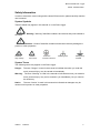
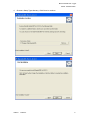
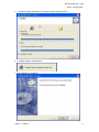
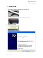
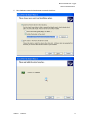
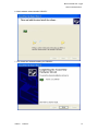
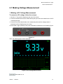
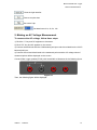
Bluetooth/USB Data Logger USER’S MANUAL Hantek 365A/B/C/D/E/F Version 1.0.2 www.hantek.com Content General Safety Summary ................................................................................................ 1 Chapter 1 Getting Start ................................................................................................... 3 1.1 General Check ..................................................................................................... 4 1.2 The User interface ............................................................................................... 5 1.3 Install Software .................................................................................................... 7 1.3 Install Driver ....................................................................................................... 10 Chapter 2: Operating Data Logger............................................................................... 13 2.1 Making Voltage Measurement ............................................................................ 14 2.2 Making Current Measurement............................................................................ 16 2.3 Measuring Resistance Values............................................................................ 20 2.4 Making a Diode Measurement ........................................................................... 21 2.5 Making a Capacitance Measurement ................................................................. 23 2.6 Selecting Automatic/Manual Range Adjustment................................................. 24 2.7 Taking a Relative Measurement ........................................................................ 25 2.8 Temperature Measurement................................................................................ 26 Chapter 3: Appendix ..................................................................................................... 27 Appendix A Specifications ....................................................................................... 28 Appendix B: General Maintenance .......................................................................... 31 Bluetooth/USB Data Logger Hantek 365A/B/C/D/E/F General Safety Summary Review the following safety precautions carefully before operate the device to avoid any personal injuries or damages to the device and any products connected to it. To avoid potential hazards use the device as specified by this user’s guide only. To Avoid Fire or Personal Injury. Correctly Plug in and Pull out. When the Data Logger probes are connecting to the voltage source, please do not plug in or pull out. Check All Terminal Ratings. To avoid fire or shock hazard, observe all ratings and markings on the product. Consult the product manual for further ratings information before making connections to the product. Do Not Operate With Suspected Failures. If suspected damage occurs with the device, have it inspected by qualified service personnel before further operations. Provide Proper Ventilation. Refer to the installation instructions for proper ventilation of the device. Do not operate in Wet/Damp Conditions. Do not operate in an Explosive Atmosphere. Keep Product Surfaces Clean and Dry. USER’S MANUAL 1 Bluetooth/USB Data Logger Hantek 365A/B/C/D/E/F Safety Information In order to ensure the correct using and the best efficient service, please carefully read the user’s manual. System Symbols These symbols may appear in this manual or on the Data Logger. Warning: “Warning” identifies conditions and actions that pose hazards to the users. Caution: “Caution” identifies conditions and actions that may damage the product or other properties. DANGER: High Voltage Refer to the manual Protective Condutor Terminal Chassis grand Earth(grand) Terminal System Terms The following terms may appear on the Data Logger: Danger: The term “Danger” is used in the manual to indicate that when you read this mark, personal injury may be caused to immediately. Warning: The term “Warning” is used in the manual to indicate that when you read this mark, personal injury may not be caused to you immediately, but you need to be cautionary. Notice: The term “Notice” is used in this manual to indicate that damages may be caused on this product or other properties. USER’S MANUAL 2 Bluetooth/USB Data Logger Hantek 365A/B/C/D/E/F Chapter 1 Getting Start General Check The User interface Install Software Install Driver USER’S MANUAL 3 Bluetooth/USB Data Logger Hantek 365A/B/C/D/E/F 1.1 General Check When you have got a new Hantek365 series Data Logger, it is suggested that you should perform a general inspection on the instrument according to the following steps: Check the shipping container for damage: Keep the damaged shipping container or cushioning material until the contents of the shipment have been checked for completeness and the instrument has been checked mechanically and electrically. Check the accessories: Accessories supplied with the instrument are listed in “Accessories” in this manual. If the contents are incomplete or damaged, please notify our distributor at your local area or the sales department. Check the instrument: In case there is any mechanical damage or defect, or the instrument does not operate properly or fails performance tests, please notify our distributor at your local area or the sales department. USER’S MANUAL 4 Bluetooth/USB Data Logger Hantek 365A/B/C/D/E/F 1.2 The User interface Click the software icon on the desk after you finished the software setting and equipment connecting. Then a user interface will be showed as follows: Description: 1. Data List 2. Description DC: DC voltage/DC current measurement AC: AC voltage/AC current measurement : Diode measurement : On-Off test : Capacitance measurement 3. Manual/Auto: Select manual or auto measurement type. 4. Measured value 5. Trend chart 6. Voltage button 7. Current button USER’S MANUAL 5 Bluetooth/USB Data Logger Hantek 365A/B/C/D/E/F 8. Resistance button 9. Diode button 10. On-Off test 11. Capacitance button 12. Temperature measurement 13. DC: click DC to switch to AC. 14. Auto: Click Auto to switch to Manual mode 15. Relative Measurement 16. Stop/Run: Stop or start acquire data 17. Help menu 18. Data Interval: 1s~100s 19. Save data 20. Clear data list USER’S MANUAL 6 Bluetooth/USB Data Logger Hantek 365A/B/C/D/E/F 1.3 Install Software Caution: You must install the software before using the Data Logger. 1. While in Windows, insert the installation CD into the CD-ROM drive. 2. The installation should start up automatically. Otherwise in Windows Explorer, switch to the CD-ROM drive and run Setup.exe. 3. The software Installation is started. Click 'Next' to continue. USER’S MANUAL 7 Bluetooth/USB Data Logger Hantek 365A/B/C/D/E/F 4. Choose a Setup Type directory. Click 'Next' to continue. USER’S MANUAL 8 Bluetooth/USB Data Logger Hantek 365A/B/C/D/E/F 5. Check the setup information. Click Next to start copying of Files. 6. Updating System Configuration. 7. The installation is complete. USER’S MANUAL 9 Bluetooth/USB Data Logger Hantek 365A/B/C/D/E/F 1.3 Install Driver 1. Connect the A-Type Plug of USB cable to your PC’S USB port. 2. Connect the B-Type Plug of USB cable to Hantek365’s USB port. 3. New hardware is found. 4. New hardware search wizard starts. USER’S MANUAL 10 Bluetooth/USB Data Logger Hantek 365A/B/C/D/E/F 5. New hardware search wizard starts to search the driver. USER’S MANUAL 11 Bluetooth/USB Data Logger Hantek 365A/B/C/D/E/F 6. New hardware wizard installs “DRIVER”. 7. The wizard has finished installing for “DRIVER”. USER’S MANUAL 12 Bluetooth/USB Data Logger Hantek 365A/B/C/D/E/F Chapter 2: Operating Data Logger The user should know how to determine the system setup from the status bar of a Data Logger. This chapter will give guides to show how to use the menus and perform basic measurements. Making Voltage Measurement Making Current Measurement Measuring Resistance Values Making a Diode Measurement Making a Capacitance Measurement Selecting Automatic/Manual Range Adjustment Taking a Relative Measurement Temperature Measurement USER’S MANUAL 13 Bluetooth/USB Data Logger Hantek 365A/B/C/D/E/F 2.1 Making Voltage Measurement 1. Making a DC Voltage Measurement To measure a DC voltage, follow these steps: 1. Click the “V” key and DC appears at the top of the screen. 2. Connect the black lead into the COM banana jack input and the red lead into the V/Ω/C banana jack input. 3. Connect the red and black leads to the measured points and the voltage value of measured points is displayed on the screen. Connect Data Logger probes(HT325) with Hantek365 as illustrated in the following figure: Figure 2-1 Then, the following figure will be displayed: Figure 2-2 DC Voltage Measurement : Save data as .txt. USER’S MANUAL 14 Bluetooth/USB Data Logger Hantek 365A/B/C/D/E/F : Clear the right data list. : Start to acquire data. : Get users’ help. : Set data interval 1s, 2s, 5s, 10s. 2. Making an AC Voltage Measurement To measure the AC voltage, follow these steps: 1) Click the “V” key and DC appears on the screen. 2) Click “DC” key and AC appears on the screen. 3) Connect the black lead into the COM banana jack input and the red lead into the V/Ω/C banana jack input. 4) Connect the red and black leads to the measured points and the AC voltage value of measured points will be displayed on the screen. Connect Data Logger probes(HT325) with Hantek365 as illustrated in the following figure: Figure 2-3 Then, the following figure will be displayed: USER’S MANUAL 15 Bluetooth/USB Data Logger Hantek 365A/B/C/D/E/F Figure 2-4 AC Voltage Measurement The user can select Auto measure and Manual measure. Voltage range can be set 60.00mV, 600.0mV, 6.000V, 60.00V, 600.0V. 2.2 Making Current Measurement 1. Making a DC Current Measurement To measure a DC current which is less than 600mA, follow these steps: 1) Click the “A” key and then “DC” appears on the screen. The unit on the main reading screen is “mA”. Click “A” key to switch the measurement between mA and A. The default is 600mA. Click “Auto” key to switch the measurement range from 60mA to 600mA. 2) Connect the black lead into the COM banana jack input and the red lead into the mA banana jack input. 3) Connect the red and black leads to the measured points and the DC current value of measured points will be displayed on the screen. USER’S MANUAL 16 Bluetooth/USB Data Logger Hantek 365A/B/C/D/E/F Connect Data Logger probes(HT325) with Hantek365 as illustrated in the following figure: Figure 2-5 Then, the following figure will be displayed on the screen: Figure 2-6 DC current Measurement for 600mA To measure a DC current which is larger than 600mA, follow these steps: 1) Click the “A” key and then “DC” appears on the screen. The unit on the main reading screen is mA. 2) Click “A” key to switch to 10A measurement, the unit on the main reading screen is A. 3) Connect the black lead into the COM banana jack input and the red lead into the 10A banana jack input. 4) Connect the red and black leads to the measured points and the DC current value of the measured points will be displayed on the screen. 5) Click “A” to return to 600mA measurement. USER’S MANUAL 17 Bluetooth/USB Data Logger Hantek 365A/B/C/D/E/F Connect Data Logger probes(HT325) with Hantek365 as illustrated in the following figure: Figure 2-7 Then, the following figure will be displayed on the screen: Figure 2-8 DC current Measurement for 10A 2. Making an AC Current Measurement To measure an AC current which is less than 600mA, follow these steps: 1) Click the “A” key and then “DC” appears on the screen. The unit on the main reading screen is “mA”, and “mA” will display on the screen, Click “mA” to switch the measurement between mA and 10A. The default is 600mA. 2) Click “DC” key and AC will display on the screen. 3) Connect the black lead into the COM banana jack input and the red lead into the mA banana jack input. 4) Connect the red and black leads to the measured points and the AC current value of measured points will be displayed on the screen. USER’S MANUAL 18 Bluetooth/USB Data Logger Hantek 365A/B/C/D/E/F Connect Data Logger probes(HT325) with Hantek365 as illustrated in the following figure: Figure 2-9 Then, the following figure will be displayed on the screen: Figure 2-10 AC current Measurement for 600mA To measure an AC current which is larger than 600mA, follow these steps: 1) Click the “A” key and then “DC” appears on the screen. The unit on the main reading screen is mA. 2) Click the “DC” key and then “AC” appears on the screen. 3) Click “mA” key to switch to10A measurement, the unit on the main reading screen is A. 4) Insert the black lead into the COM banana jack input and the red lead into the 10A banana jack input. 5) Connect the red and black leads to the measured points and the AC current value of the measure points will be displayed on the screen. 6) Click “A” to return to 600mA measurement. USER’S MANUAL 19 Bluetooth/USB Data Logger Hantek 365A/B/C/D/E/F Connect Data Logger probes(HT325) with Hantek365 as illustrated in the following figure: Figure 2-11 Then, the following figure will be displayed on the screen: Figure 2-12 AC current Measurement for 10A 2.3 Measuring Resistance Values To measure a resistance, follow these steps: 1) Click the “OHM” key and then resistance measurement window appears on the screen. 2) Connect the black lead into the COM banana jack input and the red lead into the V/Ω/C banana jack input. 3) Connect the red and black test leads to the resistor. The resistance value is shown on the screen in Ohm. USER’S MANUAL 20 Bluetooth/USB Data Logger Hantek 365A/B/C/D/E/F Connect Data Logger probes(HT325) with Hantek365 as illustrated in the following figure: Figure 2-13 Then, the following figure will be displayed on the screen: Figure 2-14 Resistance Measurement 2.4 Making a Diode Measurement To make a measurement on the diode, follow these steps: 1) Click the “Diode” key and a diode symbol appears at the top of the screen. 2) Connect the black lead into the COM banana jack input and the red lead into the V/Ω/C banana jack input. 3) Connect the red and black leads to the diode and the voltage value of the diode is displayed on the screen in volt. Connect Data Logger probes(HT325) with Hantek365 as illustrated in the following figure: USER’S MANUAL 21 Bluetooth/USB Data Logger Hantek 365A/B/C/D/E/F Figure 2-15 Then, the following figure will be displayed on the screen: Figure 2-16 Diode Measurement To perform an On-Off test, follow these steps: 1) Click the “CONTI” key and then On-Off indictor appears on the top of the screen. 2) Connect the black lead into the COM banana jack input and the red lead into the V/Ω/C banana jack input. 3) Connect the red and black leads to the tested points. If the resistance value of the test points is less than 10 Ω, you will hear beep sound from the test tool. Connect Data Logger probes(HT325) with Hantek365 as illustrated in the following figure: Figure 2-17 USER’S MANUAL 22 Bluetooth/USB Data Logger Hantek 365A/B/C/D/E/F Then, the following figure will be displayed on the screen. Figure 2-18 On-Off Measurement 2.5 Making a Capacitance Measurement To measure a capacitance, follow these steps: 1) Click the “CAP” key and a capacitor symbol appears on the top of the screen. 2) Connect the black lead into the COM banana jack input and the red lead into the V/Ω/C banana jack input. 3) Connect the red and black leads to the capacitor and the capacitance value is displayed on the screen in μF or nF. Connect Data Logger probes(HT325) with Hantek365 as illustrated in the following figure: Figure 2-19 Then, the following figure will be displayed on the screen. USER’S MANUAL 23 Bluetooth/USB Data Logger Hantek 365A/B/C/D/E/F Figure 2-20 Capacitance Measurement 2.6 Selecting Automatic/Manual Range Adjustment The default range mode of the instrument is automatic range. If you are using the DC/AC mode, to switch to the manual range, do these steps: 1) Click “Auto” key to enter the manual range mode and then Manual is displayed on the top of the screen. 2) Under the manual range mode, the measuring range is increased by a stage, Click “Auto” to switch manual. 3) Click “Manual” key to switch back to the automatic range mode and then Auto is displayed on the top of the screen. Attention: capacitance measurement without manual range mode. USER’S MANUAL 24 Bluetooth/USB Data Logger Hantek 365A/B/C/D/E/F 2.7 Taking a Relative Measurement A currently measured result relative to the defined reference value is displayed in a relative measurement. The following example shows how to take a relative measurement. At first, it is required to acquire a reference value. 1) Click the V/A/OHM/CAP key. 2) Connect the black lead into the COM banana jack input and the red lead into the V//Ω/C banana jack input. 3) Connect the red and black test leads to the tested device. The value is shown on the screen. 4) Click key then is displayed on the top of the screen. The saved reference value is displayed beside. Then, the following figure will be displayed on the screen. Figure 2-21 Relative Measurement USER’S MANUAL 25 Bluetooth/USB Data Logger Hantek 365A/B/C/D/E/F 2.8 Temperature Measurement The series of Bluetooth/USB Data Logger can measure temperature. 1) Click the T key. 2) Connect the black lead into the mA banana jack input and the red lead into the V//Ω/C banana jack input. 3) Connect the red and black test leads to the tested device. The value is shown on the screen. Figure 2-22 Connect the thermocouple sensor of the metal parts with the tested device. Then, the following figure will be displayed on the screen. Figure 2-23 Temperature Measurement Click C key to switch to Fahrenheit. And Click F key to switch to Celsius. USER’S MANUAL 26 Bluetooth/USB Data Logger Hantek 365A/B/C/D/E/F Chapter 3: Appendix Appendix A: Specifications Appendix B: Accessories Appendix C: General maintance USER’S MANUAL 27 Bluetooth/USB Data Logger Hantek 365A/B/C/D/E/F Appendix A Specifications Specification: Data Logger Mode Maximum Resolution DMM Testing Modes Maximum Input Voltage Maximum Input Current Input Impedance 6000 Counts Voltage, Current, Resistance, Capacitance, Diode & Continuity AC: 600V DC: 800V AC: 10A DC: 10A 10MΩ Data Logger Specification Range Accuracy DC Voltage AC Voltage DC Current AC Current Resistance Capacitance USER’S Resolution 60.00mV 10uV 600.00mV 100uV 6.000V 1mV ±1%±1 digit 60.00V 10mV 600.0V 100mV 800V 1V 60.00mV 10uV 600.0mV 100uV ±1%±3 digit 6.000V 1mV 60.00V 10mV 600.0V 100mV 60.00mA ±1.5%±1 digit 10uA 600.0mA ±1%±1 digit 100uA 6.000A 1mA ±1.5%±3digit 10.00A 10mA 60.00mA ±1.5%±3digit 10uA 600.0mA ±1%±1 digit 100uA 6.000A 1mA ±1.5%±3digit 10.00A 10mA 600.0 ±1%±3digit 0.1Ω 6.000K 1Ω 60.00K 10Ω ±1%±1digit 600.0K 100Ω 6.000M 1KΩ 60.00M ±1.5%±3digit 10KΩ 40.00nF 10pF 400.0nF 100pF 4.000uF 1nF ±1%±1digit 40.00uF 10nF 400.0uF 100nF Attention: The smallest capacitance value that can be measured is 5nF. MANUAL 28 Bluetooth/USB Data Logger Hantek 365A/B/C/D/E/F Temperature Diode On-Off Test 100℃~1000℃ 0~100℃ -200℃~0 0V~2.0V <10Ω 1℃ 0.1℃ 1℃ ±2%±3digit Difference: Type Hantek365A Bluetooth Lithium battery RMS iPad Supporting - - - - Hantek365B - Hantek365C Hantek365D Hantek365E Hantek365F - Yes - Yes ① Yes - - Yes ① Yes Yes - Yes ② Yes - Yes Yes ② Yes Yes Yes ① Connect the device with windows PC via Bluetooth with Bluetooth adapter. ② Connect the device with windows PC with Bluetooth adapter, and connect with iPad via Bluetooth directly. Support the third generation or higher versions, and all series of iPad mini. USER’S MANUAL 29 Bluetooth/USB Data Logger Hantek 365A/B/C/D/E/F Appendix B: Accessories Standard accessories Data Logger Probes x 2 A USB Cable A PC software CD of the Data Logger A Thermocouple Sensor Optional accessory Bluetooth adapter(Optional accessory for Hantek365E and Hantek365E) USER’S MANUAL 30 Bluetooth/USB Data Logger Hantek 365A/B/C/D/E/F Appendix C: General Maintenance General Care Do not store or leave the Data Logger where the device will be exposed to direct sunlight for long periods of time. Caution To avoid damages to the device or probes, do not expose them to sprays, liquids or solvents. To avoid damages to the surface of the device or probes not use any abrasive or chemical cleaning agents. Cleaning Inspect the device and probes as often as operating conditions require. Make sure the device disconnect form all power sources. To clean the exterior surface, perform the following steps: 1. Remove loose dust on the outside of the Data Logger and probes with a lint-free cloth to avoid scratching the clear glass display filter. 2. Use a soft cloth dampened with water to clean the device. USER’S MANUAL 31