1
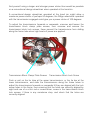
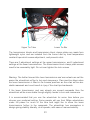
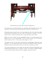
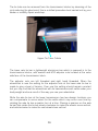
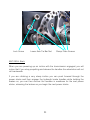
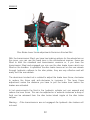
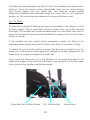
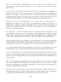
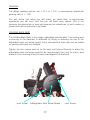
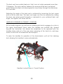
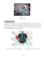
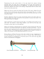
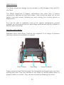
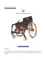
Revision Version 12.3.07
The
WILLGO Wheelchair
USER MANUAL
Important :
Please read and fully understand this manual before attempting to operate this
wheelchair. Pay particular attention to the warnings highlighted throughout the
manual.
1
INDEX
INTRODUCTION
Pg
4
INSTRUCTION MANUAL COVERAGE
Pg
5
SAFETY FIRST
Pg
5
QUICK START GUIDE
Pg
6
PACKAGING
Pg
6
TRANSMISSION
Pg
11
CLOCK SPRING
Pg
14
TIE TUBE, TIE BAR
Pg
18
ANTI-ROLL BACK
Pg
21
BRAKES
Pg
19
MANOUVERING
Pg
25
GEARING
Pg
27
FOLDING BACK REST
Pg
27
HANDLES IN TRANSIT POSITION
Pg
28
WHEELS AND TYRES
Pg
31
FRONT WHEEL CASTOR ANGLE
Pg
31
ANTI TIP TUBE
Pg
31
2
INDEX
MAINTENANCE
Pg
31
SEATING AND FABRIC
Pg
31
HAND GRIPS
Pg
34
OPERATION
Pg
34
SERIAL NUMBER
Pg
35
STANDARDS
Pg
35
SERVICING SCHEDULE
Pg
36
ADVANCED SERVICING
Pg
37
PACKAGING
Pg
40
WEIGHTS, WIDTHS,
Pg
41
TORQUE SETTINGS
Pg
41
CONTACT DETAILS
Pg
42
DEALER NOTES
Pg
43
WARRANTY
Pg
44
UPDATES
Pg
45
3
INTRODUCTION
Willgo is the result of a team effort by a number of companies to design and
develop a wheelchair for users offering all the features of a conventional
wheelchair with additional features similar to a bicycle. The design can be used
around the home, office, shops, leisure, and even off road. It is suitable for
young and old, within the one design, without having to resort to battery power
or the car.
The Willgo wheelchair is available with or without the transmission. The
wheelchair frame is manufactured from high grade aerospace aluminium. The
wheelchair comes with similar options to any similar rigid fame wheelchair, and
is manufactured to current Standards.
The transmission unit can be factory fitted or retrofitted to the wheelchair and is
simply bolted to the frame.
4
The handles are engaged or disengaged from the transmission in seconds and
are used to power the wheelchair, they can be locked forward and down to a
position below the level of the seat to assist side transfers and transportation.
The two fully independent transmissions mounted either side of the frame are
engaged by moving toggles located in the centre of the rear wheel hubs. The
handles are raised to the vertical and power is applied by pushing away,
sitting upright and loading against the back rest, not lunging forward as when
powering at the hand rims.
This action causes the upper transmission pulley wheels to rotate and pull on
the flat pulley belts. The flat pulley belts pull on the lower transmission pulley
wheels within which are located one way clutches. The clutches engage
instantly and automatically to the rear wheel drive axle and cause the rear
wheels to rotate.
At the end of the power stroke the clutches disengage while the handles are
returned to the vertical in readiness for the next power stroke.
INSTRUCTION MANUAL COVERAGE
This User Manual covers the installation, operation, general servicing and
maintenance of the Willgo wheelchair.
SAFETY FIRST
The Willgo wheelchair has been designed so that most parts are easily
accessible for general servicing and maintenance.
While you will be able to undertake some general servicing and maintenance
yourself, if you are unsure or have any questions, or are planning any involved
work on the wheelchair this should be carried out by your dealer or mobility
workshop.
In all instances remember Safety First, wear hand and eye protection, and if in
doubt, ask.
The Willgo wheelchair is not to be used while traveling in a vehicle,
recommended stowage in a vehicle is with the wheels removed, the back rest
down, in the boot of the vehicle.
5
QUICK START GUIDE
Packaging
If the Willgo wheelchair has arrived boxed, use a knife or scissors to carefully
cut the tape across the box top middle, and the box top sides, and open the
box.
You will see the wheels packaged either side of the wheelchair, remove the
wheels and set to one side, then remove the wheelchair.
Ply wood sheeting protects the base of the box from the front wheels and the
rear frame hooks that protect the disc plates from grounding. Card board
sheeting protects the rear wheels from touching the frame.
6
Back Rest Wheel Guards
Raise the back rest wheel guards and note that the horizontal slot matches to
the M5 screw with 2 washers and M5 nut in the seat frame tubes.
Unscrew and remove the M5 screws with washers and nuts from the seat
frame tubes. Swing the back rest wheel guards into position and fit the M5
screws with 1 washer outside and 1 washer inside the back rest wheel guard.
Adjust the back rest to a rearwards setting for quick start and screw the M5
screw through the frame till it is tight, fit the M5 nut and tighten. This will ensure
your body weight is set to the rearwards making the wheelchair particularly
stable while you learn operations.
The back rest wheel guards are secured to the back rest frame tubes by M5
screws, fit the steel washer on the inside, and the black plastic washer on the
outside, adjust the screw tension so that the back rest rotates forwards and
rearwards easily.
Lock the back rest wheel guards into position by rotating to the maximum
rearwards and then push the back rest wheel guards downwards so that the
slot engages with the screw.
Rear Wheels
There are 2 quick release wheel axles, depress the quick release wheel axle
end buttons and push the wheel axles through the centre hole in the wheel
hubs where the red toggles are located.
Depressing the wheel axle end button moves a cam within the wheel axle
allowing 2 ball bearings to recess in to the wheel axle. The function of the ball
bearings is to secure the wheel and wheel axle to the lower transmission axle.
Rock the wheelchair to one side and taking one of the rear wheels depress the
quick release wheel axle end button, then push the wheel axle through the
centre hole in the lower transmission drive axle till it will go no further, then
release the quick release wheel axle end button.
7
To check that the ball bearings have popped out at the other end of the quick
release wheel axle, and the rear wheel is locked in position, pull on the wheel
hub to check that it does not slide off the lower transmission axle, then fit the
other side rear wheel.
Transmission Engage Disengage
At the hub of each rear wheel you will see a red toggle, this can be flipped over
to engage or disengage the transmissions from the rear wheels.
Note the M10 indexing bolt on the upper transmission segment and pull it
outwards, this will allow the handles to raise automatically.
Flip the toggles at the rear wheel hubs over and push on the Handle, if the
transmission is engaged the rear wheel will rotate.
To disengage the transmissions flip the toggles over to the other side. Flipping
the toggles over causes 2 pins to extend or recess from the rear wheel hub.
These 2 pins engage or disengage the drive to the rear wheels from the lower
transmission drive axles.
Transit to and from Wheelchair
Push the handles fully forward to engage the M10 Indexing Bolt. You will hear it
click in to place. This will hold the handles down and out of the way while you
are using the wheelchair with the transmission disengaged, or during transit to
and from the wheelchair.
Remember to engage the parking brakes which are located below the upper
transmissions, you can use these when stationary for a long time or during
transit.
Operation
With the transmissions disengaged the wheelchair can be used like any other
conventional wheelchair by powering at the rear wheel hand rim.
To use the wheelchair with the transmission engaged pull the indexing bolt
outwards, to allow the handles to rise. Flip the toggles over. Push the handles
away from you.
8
When powering with the transmission engaged and at the handles the power
efficiency is about 225% more than when powering conventionally at the rear
wheel hand rim.
To turn the wheelchair, brake on one side and push on the other side. Pushing
the handles together for forward motion is the best method rather than
alternating the power strokes as on a bicycle.
To brake in a straight line, brake on both sides equally. Braking more on one
side than the other will cause the wheelchair to turn.
Test turning the wheelchair on the spot by holding one side brake fully on and
pushing on the other side so the wheelchair goes around in a circle, then try
braking and pushing on the other side to turn the wheelchair on the spot in the
other direction.
The disc brakes are powerful and we recommend you learn their operation till
confidence is gained, avoid any undue or extreme unequal braking pressure.
Using the lever operated disc brakes means there is no risk of friction burns as
might be experienced when braking a conventional wheelchair at the hand rim.
Transmission Adjustment
The transmissions can be moved forwards or rearwards along the frame tubes
for wheelchair users with longer or shorter arms at the upper transmissions,
and tip or balance at the lower transmissions. The lower transmissions have
been preset to a middle position giving a stable wheelchair with a good level of
balance. Do not use excessive power or adjust the transmissions till you have
gained in confidence.
Safety
Note that with the transmission engaged the wheelchair has an anti roll back
feature, it will not roll backwards down an incline.
This safety feature also means that if you apply excessive power you will not be
able to stop the wheelchair tipping over backwards by reversing the wheel
rotation.
9
If you feel unsure, or begin using the wheelchair over terrain, you can fit the
Willgo anti tip tube at the rear of the wheelchair.
The anti tip tube locates to the left rear hook in the frame and can be swivelled
around to a forward position when not in operation by depressing the button
clip.
This Quick Start guide will get you started with the Willgo wheelchair but ensure
that you also fully read and fully understand the User Manual.
While you will be able to undertake some general servicing and maintenance, if
you are unsure or have any questions, or are planning any involved work on the
wheelchair, this should be carried out by your dealer or mobility workshop.
In all instances remember Safety First, wear hand and eye protection, and if in
doubt, ask.
10
TRANSMISSION
The transmission units can be easily fitted or removed and can also be
adjusted forwards and rearwards along the frame to the preferred position of
balance, power and ergonomics.
To engage the transmissions, flip over the toggles, which are located in the
centre hubs of the rear wheels, this engages the lock pins to the multi hole ring
plate in the drive axle and engages the transmission. Pull out the indexing bolt
which holds the handles down forward, the handles rise automatically, then
push the handles away from you for forward motion.
Transmission Engagement Toggle
Quick Release Button
As you push on the handles the wheelchair will power forward until you reach
the end of the power stroke. Momentum will then carry the wheelchair forward
in exactly the same way as a conventional wheelchair while you return the
handles back to the vertical for the next power stoke.
Adjustment
Use the wheelchair for a time before deciding to adjust these settings, you will
find that the upper transmission may be best set with an adjustment slightly to
the rear of where you think it would be preferred, this is because you will soon
11
find yourself using a longer and stronger power stroke than would be possible
on a conventional design wheelchair when operated at the hand rim.
A conventional design wheelchair operated at the hand rim might allow a
maximum power stroke of perhaps 50 degrees, the Willgo wheelchair operated
with the transmission engaged could give you a power stroke of 100 degrees.
To adjust the transmissions forwards or rearwards, unscrew and loosen the
transmission block clamp plate screws, then unscrew and remove the
transmission block lock screws, these prevent the transmissions from sliding
along the frame tube when high levels of power are applied.
Transmission Block Clamp Plate Screws
Transmission Block Lock Screw
Push or pull on the tie tube at the upper transmissions, or the tie bar at the
lower transmissions, and slide the transmissions along the frame tubes to
adjust the transmissions forwards or rearwards till they are aligned with the lock
screw holes in the frame, then ensuring that the holes are correctly aligned by
sight and use of a a thin rod or screw driver, screw in the transmission block
lock screws, if there is any resistance stop, and check that the holes are
correctly aligned.
12
Upper Tie Tube
Lower Tie Bar
The transmission blocks and transmission block clamp plates are made from
lightweight nylon and are isolated from the frame tube by hard temperature
resistant tape which eases adjustment, and prevents stick.
There are 2 adjustment settings at the upper transmissions, and 5 adjustment
settings at the lower transmissions. The transmission block clamp plate screws
need to be reasonably tight. Do not over tighten the lock screws.
Warning: The further forward the lower transmission and rear wheels are set the
easier the wheelchair will be to turn and manoeuvre. Care must be taken when
the lower transmission is fitted in the forward positions as the chair will be less
stable rearwards and could result in injury if the chair tips backwards.
If the lower transmission and rear wheels are moved rearwards then the
wheelchair will be more stable though slightly harder to turn and manoeuvre.
It is recommended that you use the wheelchair for some time before you
choose your preferred setting. Some people will use their Willgo wheelchairs
under full power for much of the time and might like to move the lower
transmissions further to the rearwards. The wheelchair has parameters in
design giving stability laterally, at all speeds, with ease of manoeuvrability.
13
Tensioning the clock spring
During adjustment of the transmissions forwards or rearwards the clock spring
in the lower pulley wheels automatically compensates in adjustment however,
you might wish to reset the tension in the pulley belts.
To check the tension in the pulley belt push the handles forwards against the
tension in the clock spring. The tension should be sufficient to keep the handle
pressed in to your hand during the return from the power stroke. If it has not
changed substantially then you may leave the adjustment of the pulley belt
tension.
If you wish to increase the pulley belt tension there is a set procedure. Remove
the screw securing the upper pulley wheel to the upper axle and remove the
pulley wheel.
Upper Pulley Wheel Screw
Pulley Belt
Wind almost all of the pulley belt on to the lower pulley wheel. Give the pulley
belt a pull to set the clock spring tension at the lower pulley wheel. Wind on
about one revolution of the pulley belt to the upper pulley wheel with the upper
pulley wheel approximately alongside the upper axle. Pull the upper pulley
wheel against the pulley belt tension to a position along side the upper axle
and then rotate it one quarter turn to give the correct pulley belt tension.
14
Clutch
Clock Spring within Lower Pulley Wheel
Drive Axle
Finally, press the upper pulley wheel on to the upper axle and replace the
screw. Check that the pulley belt tension is sufficient to keep the handle
pressed in to your hand during the return from the power stroke. You can
increase the pulley belt tension by removing the upper pulley wheel to give it
one more quater turn.
Do not over tension the pulley belt, as the tension increases you will need to
use more energy to overcome this. If the belt is over tensioned it is possible to
over compress the clock spring in the lower transmission at the end of the
power stroke resulting in damage to the pulley, and the spring, and the clock
spring M3 pins which are located one acting between the clock spring and the
lower pulley wheel, and one acting between the clock spring and the
transmission block, we recommend between a quarter and a half a turn tension
at the upper pulley wheel.
15
Clock Spring
To remove the lower pulley wheel and gain access to the clock spring first
remove the screw securing the upper pulley wheel and remove the upper
pulley wheel, this releases tension in the clock spring and pulley belt.
Key 1
Clutch
Key 2
16
Circlip
Clutch Sleeve
Remove the circlip at the lower axle clutch sleeve using circlip pliers, this
secures the lower pulley wheel to the clutch sleeve, ensure that you use gloves
and eye protection.
Slide off the nylon washer and the lower pulley wheel from the clutch sleeve, it
may be necessary to use light levering to assist in this.
Key 1. secures the clutch sleeve to the internal diameter of the clutch. Key 2.
secures the external diameter of the clutch to the lower pulley wheel.
The clutch is keyed and glued to the lower pulley wheel, the clutch and key 2
can be removed from the lower pulley wheel by steaming of the joint reducing
the glue bond, and pressing out of the clutch from the lower pulley wheel, this
is a skilled procedure best carried out by your dealer or mobility repair
workshop.
With the lower pulley wheel removed from the clutch sleeve it is now possible to
remove or reset the clock spring.
Pull out the clock spring from its recess in the lower pulley wheel. Care should
be taken to protect fingers. Use gloves and eye protection.
The clock spring is stainless steel and is under tension. Check that the M3
clock spring pins are not bent, if they are, straighten using pliers. The pins are
screwed into place. If too badly damaged they can be unscrewed using pliers
and replacements fitted.
To fit the clock spring into the recess in the lower pulley wheel, hold the lower
pulley wheel up against the lower axle and look at the direction the pulley belt
will take from the top of the lower pulley wheel, remember this and imagine the
end of the clock spring attached to the end of the pulley belt, then invert or
rotate the clock spring so that it is the other side up, to achieve the correct
direction for fitting.
Slide the clock spring end loop on to the pulley wheel clock spring pin and
hold it there with a finger, remember to wear gloves and eye protection. With
your other hand, hold the clock spring against the lower pulley wheel and begin
to rotate the lower pulley wheel.
17
As you rotate the lower pulley wheel the clock spring tension will build up and
you will see that the clock spring will reduce in diameter. Keep rotating and
compressing the spring until you are able to press the clock spring in to the
pulley wheel clock spring recess.
Now take the lower pulley wheel with the clock spring in place and slide it back
on to the lower axle shaft to a position where you can just see the end of the
clock spring end loop and the transmission block clock spring pin. Rotate the
lower pulley wheel till they are both lined up and press the lower pulley wheel
fully into position.
To make fitting easier you can slightly press out the clock spring loop in the
outer end of the clock spring using a thin screw driver, this will make the loop
more visible when you locate the loop to the pin in the transmission block.
Holding the lower pulley wheel in position slowly rotate the brake disc till the
key ways in the clutch and the lower pulley wheel are aligned, press in the key.
The key should be an easy fit, if it is too tight the key can be lightly knocked in
with a soft aluminium drift or filed slightly to remove any high spots.
Take the pulley belt and pull it, to make sure the clock spring is the the correct
way round, then replace the nylon washer spacer and the circlip.
There are two nylon washer spacers, one washer spacer locates between the
transmission block and the lower pulley wheel, the second washer spacer
locates between the lower pulley wheel and the circlip in the end of the clutch
sleeve.
The pulley belt is secured to the pulley wheels with contact adhesive glue and
a retaining screw. The pulley belt locks on to the pulley wheel as it is wound
round. The pulley belt is protected from contact with the locking screw by a
length of adhesive backed loop tape.
Axle Tie Bar Tie Tube
The transmissions are secured forwards or rearwards along the frame tubes by
the transmission block clamp plate screws, two each side at the upper
transmissions, three each side at the lower transmissions, and lock screws
which pass through each transmission block into the frame tube, and tie tubes
at the upper transmissions, and tie bars at the lower transmissions.
18
Flat machined on Lower Axle Tie Bar for adjustment
The forces upon the transmissions are forwards and rearwards as you exert
load upon the transmissions during operation and also a rotational force.
During the power stroke force on the transmissions will act to drive the upper
transmissions backwards and the lower transmissions forwards. The lock
screws work to keep the transmissions in place along the frame tubes.
While you may be able to exert substantial power to the transmissions the
greater force is in your body weight, this force over a bump or rut in a surface
might increase to over 1.5 times your body weight, or more.
The upper tie tube at the upper transmissions is lightweight aluminium tube
pressed in to the transmission blocks secured with general contact adhesive
smeared inside the transmission block tie tube hole, and also by collets.
The collets are glued on to the upper tie tube with Loctite 643 SuperGlue and
clamped while the glue sets, in around 1 minute. The collets act against weight
on the seat forcing the seat frame tubes together along the tie tube.
19
The tie tube can be removed from the transmission blocks by steaming of the
joint reducing the glue bond, this is a skilled procedure best carried out by your
dealer or mobility repair workshop.
Upper Tie Tube Collets
The lower axle tie bar is lightweight aluminium bar which is pressed in to the
transmissions blocks, with washer and M12 adjuster nuts located at the outer
side face of the transmission block.
The adjuster nuts are left threaded and right hand threaded. When the
wheelchair is new the setting for the adjuster nuts at the lower axle tie bar is
made to give a level of tension. Over use this setting should remain constant
but you may find that the wheelchair with its transmissions will settle under your
body weight and as a result of the way you use your wheelchair.
While the axle tie bar at the lower transmission has two design functions you
can compensate to some extent for the settle which may occur over time by
rotating the axle tie bar a quarter turn at a time. Placing a spanner on the axle
tie bar flats rotate the tie bar slowly clockwise to make the wheels more vertical,
and anticlockwise to make the rear wheels less vertical.
20
Lock Screw
Lower Axle Tie Bar Nut
Clamp Plate Screws
ANTI ROLL Back
When you are powering up an incline with the transmission engaged, you will
notice that if you stop propelling and release the handles the wheelchair will not
roll backwards.
If you are climbing a very steep incline you can push forward through the
power stroke and then engage the hydraulic brake handles while holding the
brakes on, you can then recover the handles in readiness for the next power
stroke, releasing the brakes as you begin the next power stroke.
21
BRAKES
Disc Brake Lever throw adjustment Aluminium Knurled Nut
With the transmission fitted, you have two braking options for the wheelchair on
the move, you can use the hand rims in the conventional manner, these are
fitted to both the standard and transmission versions or, if you have the
transmission fitted and engaged you can use the disc brake levers which are
fitted on the handles. In operation the disc brake levers act on the rear wheels
through hydraulic callipers to the disc plates, they are very effective and will
easily lock the rear wheels.
The aluminium knurled nut is rotated to adjust the brake lever throw, clockwise
to reduce the throw and anti-clockwise to increase it. The lever throw
adjustment varies the distance you have to pull the brake lever before the
brakes are activated.
In hot environments the fluid in the hydraulic cylinder pot can expand and
reduce the lever throw. This can be adjusted or in extreme instances a drop of
fluid can be released from the disc brake bleed nipple at the disc brake
calliper.
Warning : If the transmissions are not engaged the hydraulic disc brakes will
not work.
22
Disc Plate
Disc Brake Calliper
Disc Brake Bleed Nipple
Parking Brakes
Parking Brake with over centre lock
23
Conventional parking brakes are fitted to both the standard and transmission
versions. These are scissors action and operate using an over centre locking
lever acting against the rear wheel tyre. Two securing screws enable
adjustment forwards and rearwards along the frame tube to your preferred
position for the rear wheels and sideways for varying thickness tyres.
Pull To Brake
An alternative method of braking has been incorporated to the design in a Pull
to Brake system. This is particularly useful for wheel chair users with reduced
hand grip. The handles are pushed forwards away from the wheel chair user to
power the wheelchair and recovered rearwards in readiness for the next power
stroke as normal.
If the handles are then pulled further rearwards a brake bar fitted to the
adjustable wheel guard acts upon the brake lever which is reversed in fitting.
To adjust the pull to brake system unscrew the aluminium knurled nut on the
brake lever and continue unscrewing while pulling the handle rearwards till the
brake lever no longer acts against the brake bar.
Then screw the aluminium nut in the direction of the arrow clockwise till the
brake lever begins to act upon the brake lever, keep doing this till the disc plate
locks up when the handle is pulled backwards.
Brake Bar Slot in Wheel Guard
Pull To Brake Bar
24
Brake Lever
Sitting in the wheelchair give a slow power stroke and pull backwards on the
handles. If the wheelchair pulls to one side increase or decrease the
adjustment at the aluminium nut till the brake balance is equal.
The system is powerful and sensitive when set correctly, and and is easy to
adjust. The brake bar can be disengaged from the system by pushing it
forwards along the slide in the adjustable back rest wheel guard to the end of
the slot, then push downwards, this will set the brake bar to a point below the
level of the seat.
Brake Bar Engaged
Brake Bar Disengaged
The small screw at the hinge point of the brake lever can be rotated for further
adjustment.
The brakes are powerful, so experiment with varying the pressure exerted on
the brake lever and the lever throw adjustment at the Aluminium knurled button.
MANOUVERING
Flip Toggle over to engage/disengage Transmission
25
With the transmission disengaged you can operate and manoeuvre the
wheelchair in the conventional manner at the hand rims around the home,
office, shops.
If you want to manoeuvre the wheelchair with the transmission engaged you
have two options. To turn to the right you could push more on the left lever or
brake on the right, if you want to turn on the spot with the transmission
engaged simply brake on the one side, and push on the other side. As with a
conventional wheelchair, you will find that operation is easy and intuitive.
While you will not roll backwards on an incline while the transmission is
engaged you will also not be able to go backwards. Similar to a bicycle, or
hand cycle, imagine someone backing out of a close confined area, like a
garage, the pedals go round. The Willgo transmission must be disengaged if
you want to go backwards.
For operation in close confined areas you should use the wheelchair in its
conventional mode with the transmission disengaged and handles folded
down. If you want to go further, perhaps along a long corridor, the garden path,
to the shops, engage the transmission, raise the handles, and power away.
When powering away from stationary, apply pressure to the handles gradually,
increasing the force applied, building up to the end of the power stroke, then
coast while you recover the handles to the vertical for the next power stroke.
It is a good idea to allow the wheelchair to coast for a second before the next
power stroke. This is more energy efficient than when powering all the time.
You will notice that in the conventional mode when powering at the hand rims
that your body weight lunges forward away from the backrest during the power
stroke, this is not energy efficient, nor is it good for body posture, particularly in
the long term.
With the transmission engaged you will notice that you do not need to lunge
your body weight forward through the power stroke, you can now sit upright
and exert load against the backrest resulting in a more efficient and ergonomic
method of powering a wheelchair.
Warning : Care must be taken when descending slopes at high speed. Due to
the diameter of the front castors small stones, uneven surfaces etc. could result
in stopping of the wheelchair which may result in injury to the user.
26
GEARING
The Willgo gearing options are 1:1.12 or 1:1.37, a conventional wheelchair
gearing ratio is 1 : 1.00.
You will notice that while you will easily go faster than a conventional
wheelchair you will soon find that you will want more speed. This is not
because the wheelchair is slow but because the wheelchair is much easier to
power and has the potential to go faster.
FOLDING BACK REST
The Folding Back Rest is fully angle adjustable and lockable. The locking and
un-locking of the backrest is achieved by lifting or lowering the top of the
adjustable back rest wheel guard. Once unlocked the back rest can be folded
by pushing the back rest forward.
Tighten the lock screw and nut to the back rest tube sufficiently to allow the
adjustable back rest wheel guard to be moved easily from lock to unlock, and
prevent it from moving when you exert load against the backrest.
Lock Screw
Folding Back Rest Wheel Guard
27
Lock Screw
The back rest has a safety feature in that it can not rotate rearwards more than
15 degrees. The nylon washer between the screw and the back rest wheel
guard allows the back rest wheel guard to move freely through the slide when
it is unlocked.
Adjusting the angle of the back rest is achieved by loosening the lock screw
and nut at the seat tube. The back rest angle can then be adjusted by sliding
the back rest wheel guard forwards or rearwards to your preferred back rest
angle, then tighten the screw and nut.
HANDLES FORWARD IN TRANSIT POSITION
At the handle segment you will see an indexing bolt which engages to a hole in
the upper transmission block when the handles are pushed fully forward
beyond the horizontal, this allows the wheelchair to be operated with the
handles down and out of the way when powering at the hand rim, and easy
transit to and from the wheelchair and transport.
To raise the handles for operation of the transmission, pull out the indexing
bolt, allowing the handles to raise automatically.
Handles Locked Down in Transit Position
28
Indexing Bolt
WHEELS AND TYRES
The front and rear wheel rims are lightweight Aluminium. The rear wheels are
the patented `Willgo Go Lock` design with toggles on the outer face of the
wheel hub. As you flip the toggles over you will notice that the locking pins
extend and locate to the lower axle multi hole ring plate on the lower axle
causing engagement of the transmission.
Quick Release Axle Lock Bearings
29
Transmission Drive Locking Pins
Depressing the axle centre button in the rear wheel hub causes locking
bearings within the wheel axle to disengage from the drive axle allowing the
wheel to be easily removed from the wheelchair. To replace the wheel to the
wheelchair depress the button and holding it depressed slide the wheel axle
back into the drive axle hole.
Make sure that you push the wheel and its axle all the way, release the end
button and you should now see that the button has popped fully out. If it does
not, then you have not fully inserted the wheel into the drive axle and it is not
locked into place.
Another method to ensure you have secured the wheel to the drive axle is to
give the wheel hub a pull, it should not be possible to remove the wheel if the
locking bearings are engaged.
There should be a small amount of free play in the fitting of the wheel to the
drive axle, this assists in easy fitting however, over time this free play may
increase in which case it can be adjusted.
Adjust the freeplay by depressing the end button and removing the axle from
the wheel. You will see that there is an adjuster nut behind the button. You will
also see a flat machined into the outer tube of the axle which can be held in a
vice or with an 11mm spanner while the adjuster nut is rotated clockwise to
reduce the end play, test by adjusting a quater turn at a time.
Ensure there is sufficient free play at the axle to allow for easy engagement of
the ball bearings as they recess at the end of the axle tube, and sufficient
tension allowing full engagement of the drive pins to the multi hole ring plate
when the transmission is engaged.
Quick Release End Button
Locking Nut
30
Locking Bearings
Flat
TYRES
The front and rear tyres have Flexel puncture proof inserts. They are not air
filled so eliminating the chance of punctures. They give a similar ride to
pneumatic tyres. Standard pneumatic tyres can be fitted if preferred.
FRONT WHEEL CASTOR ANGLE
Eccentric Nuts
Front Wheel Castor
Adjust the front wheel castor angle by removing and rotating the eccentric nuts
located in the castor mounting block, and resetting them. The general rule is to
keep the front wheel hub vertical though you can experiment with this.
If the Wheelchair pulls to one side then adjustment at the castor mounting
block will resolve this. An easy method for checking if the front wheel castor is
vertical is to hold a rod against the castor mounting block and visually check.
ANTI TIP TUBE
While you are learning to operate the Willgo wheelchair it is a good idea to
install the Willgo anti tip tube. The anti tip tube is inserted into the lower left
hook at the rear of the frame. The hook protects the disc plate when the
wheelchair is set on a surface with the wheels removed.
31
A plastic tube end cap may be fitted to the end of the frame hook, remove the
plastic cap to reveal the aluminium sleeve.
Depress the button clip on the anti tip tube and insert the end of the tube into
the frame hook till the button clip engages with the bevelled slot in the frame
hook. The button clip will pop out and the anti tip tube will be secured.
The anti tip tube is removed by depressing the button clip. If the anti tip tube is
inserted beyond the end of the aluminium it will not lock, pull it out and reinsert.
With experience you will learn the balance of the Willgo wheelchair set against
power and may decide to remove the anti tip tube, alternatively you can rotate
the anti tip tube to rearwards so that it points forwards in the disengaged
position.
Anti Tip Tube engaged
Button Clip
Anti Tip Tube disengaged
If transporting the wheelchair without the wheels it is a good idea to remove the
anti tip tube if it is fitted.
32
MAINTENANCE
The Willgo wheelchair design can be worked on with Hexagon Keys and Circlip Pliers.
The Willgo wheelchair is largely maintenance free other than in routine
checking on tightness of nuts and screws. Care should be taken not to over
tighten nuts and screws following any work arising from routine checks or
adjustments.
You may be able to undertake most of the regular maintenance yourself
however, we recommend that you have Willgo serviced annually by a Dealer or
Mobility repair workshop.
SEATING AND FABRIC
Standard 25mm and 50mm Cushions are supplied. A full range of pressure
relieving cushions are available on request.
Seat Cushion
Carry Bag
Frame Protector
Frame protectors are fitted to protect the framework and wheel chair user from
chafing and cold. They are secured to the frame by double sided velcro to
prevent rotation in contact. They can be removed by releasing the velcro.
33
The seating and back rest fabric is secured by aluminium strips secured to the
frame by screws and velcro strips.
While we recommend maintaining the seating fabric tension you can adjust the
back rest fabric tension to give a hammock effect. You can do this by releasing
the screw tension in the back rest strips and releasing the velcro tension,
alternative back rest fabric tension is achieved by adjusting webbing tension.
You will notice that the cushions will settle in use to also give a hammock
effect, helping to keep the body more central to the seating.
HAND GRIPS
These are a popular choice but you can fit your own. They are a standard
bicycle type handlebar grip. To remove the old grip, insert a thin screwdriver
between the grip and the tube to un-stick the grip and spray in a small amount
of hair spray allowing working free of the grip. To fit a new grip use hair spray,
sprayed on to the tube and also into the grip, the spray will act as a lubricant
and light glue.
OPERATION
The Willgo wheelchair has been designed with the assistance of many
wheelchair users, you will soon find yourself tackling terrain and surfaces that
you would not have approached before in a conventional wheelchair.
You will find that Willgo has the ability to open up new areas of access, it will for
instance enable you to ascend slopes and kerbs. You must be cautious initially
until you are sure of the characteristics and limitations of your new Willgo
wheelchair.
When approaching a kerb a harder push on the handles will reduce load on the
front wheels and with practise you will be able to raise the front wheels off the
ground and so jump and ascend kerbs.
Willgo is a new technology, as you increase your abilities with your new Willgo
wheelchair you must always remember to be cautious, and safe.
Willgo is in continued development. You must always seek to keep within your
limits and the limits of the wheelchair.
34
SERIAL NUMBER
Each frame is individually numbered. You will find a silver label attached to the
frame of the wheelchair at the rear right side, which has manufacturer
information and a unique serial number. This serial number must be quoted
during any correspondence with the manufacturer or supplier. A duplicate of
the serial number is located within the right frame tube rear hook.
STANDARDS
The Willgo wheelchair is CE Approved and has been designed and tested to
conform to the following British and International Standards for wheelchairs as
a Class 1Medical Device:
Wheelchairs: BS EN 12183 1999
Seating: ISO 7176 - 16
Willgo is a new technology, there are no particular ways to test the transmission
system other than in use and as a result of this the most important testing will
be by wheelchair users each of whom will find new parameters and new ways
to use the design.
We are particularly interested to hear how you use your Willgo wheelchair and
any ideas you may have to help us in making Willgo the very best design
wheelchair.
35
SERVICING SCHEDULE
Every 2 weeks check all bolts for tightness.
Check belts and pulleys for damage.
Check seat and back canvases for tightness and deterioration
6
months
12
months
To ensure your Willgo wheelchair continues to give you problem free use, we
highly recommend you have your Willgo serviced annually by your dealer or
mobility repair workshop.
Tips :
To clean the nylon and aluminum parts you can use a soft cloth and a light
vegetable oil to clean, buff, polish, this will not leave a film or smear.
36
ADVANCED SERVICING
CLUTCH SLEEVES REMOVAL
The lower axles within the lower transmissions have been designed for easy
serviceability and have a right threaded clutch sleeve on the left side lower
axle, and a left threaded clutch sleeve on the right side lower axle.
To unscrew the clutch sleeves from the lower axles remove the screw and
washer holding the upper pulley wheels on to the upper axles and remove the
upper pulley wheels. This will release the pulley belt tension.
Remove the circlips from the ends of the lower axles, ensuring that you use
gloves and eye protection. Remove the nylon washer spacer and remove the
lower pulley wheels, easing away the clock spring from the clock spring
screws.
When correctly fitted, the pulley belt runs off the top of the pulley wheels.
To remove the clutch sleeve from the lower axle turn the pulley wheels around
so that the pulley belt runs off below the pulley wheels, then fit the pulley
wheels back on to the upper axle and the lower axle. Fit the key between the
clutch sleeve and clutch. Ensure that you leave a gap between the face of the
lower pulley wheel and the M3 clock spring lock screw in the side of the lower
transmission block. You can temporarily remove the screw.
Rotate the lower pulley wheel to take up any free pulley belt and then push the
handle while holding the disc brake on. Force may be required. (It may be
easier to place the wheelchair on the ground during this operation). This will
cause the clutch sleeve to unscrew from the lower axle. Remove the pulley
wheels and unscrew the clutch sleeve.
When replacing the clutch sleeve to the lower axle grease the clutch sleeve and
lower axle thread to make future removal easier, screw on the clutch sleeve by
hand till tight, then fit the lower pulley wheels. Hold the disc plate and rotate the
pulley wheel till the key slots are aligned. The keys should be an easy fit, gently
knock in with an aluminium drift or file if necessary to ensure easy fit.
37
There are two nylon washer spacers, one washer spacer locates between the
transmission block and the lower pulley wheel, the second washer spacer
locates between the lower pulley wheel and the circlip in the end of the clutch
sleeve.
Wind almost all of the pulley belt on to the lower pulley wheel. Give the pulley
belt a pull to set the clock spring tension at the lower pulley wheel. Wind on
about one revolution of the pulley belt to the upper pulley wheel with the upper
pulley wheel approximately alongside the upper axle. Pull the upper pulley
wheel against the pulley belt tension to a position along side the upper axle
and then rotate it one quarter turn to give the correct pulley belt tension.
Finally, press the upper pulley wheel on to the upper axle and replace the
screw. Check that the pulley belt tension is sufficient to keep the handle
pressed in to your hand during the return from the power stroke. You can
increase the pulley belt tension by removing the upper pulley wheel to give it
one more quater turn.
Fit the M10 screw and washer. A power stroke at the handle during normal
operation of the transmission will lock the clutch sleeve on to the lower axle.
When operating the wheelchair with the transmission engaged the power
transmitted through the transmission unloads through the rear wheels.
Excessive power levels will cause the rear wheels to slip as the power unloads.
The Disc brakes are very powerful and it is possible to exert excessive loads
through the transmission by pushing on the handles while holding the disc
brakes locked on. This is not advisable. The only circumstances when it is
permitted to follow this procedure is when unlocking the clutch sleeves from
the lower axles.
LOWER AXLE REMOVAL
Remove the upper pulley wheel, lower pulley wheel, and clutch sleeve.
Remove the disc brake calliper screws and remove the calliper, screw the
clutch sleeve on to the drive axle about ten threads and gently knock the end of
the clutch sleeve with a soft faced hammer.
The drive axle will move through the transmission block and bearings, unscrew
the clutch sleeve further and gently knock the drive axle further.
38
Remove the clutch sleeve completely and using a drift or puller remove the
drive axle from the transmission block, ensure that the drive axle end threads
are not damaged or distorted.
The bearings are glued in place with Loctite 243 thread lock glue, they can be
removed from the transmission blocks using a light drift, the process may be
made easier by steaming of the joint reducing the strength of the glue bond.
UPPER AXLE REMOVAL
Remove the upper pulley wheel, handle, and segment.
Remove the circlip at either end with circlip pliers and gently knock the lower
axle through the transmission block.
39
Procedure in preparation of Willgo for packaging :
The packaging for Willgo wheelchairs is custom made, you will note that the
bases are protected internally by sheet ply, preventing damage to the
packaging base in transit. If storing the packaging, the tape sealing the box
can be cut and the box then folded flat.
1) Rotate the handles fully forward till they lock down at the indexing bolts
.
2) Remove the M5 screws and nuts from the back rest wheel guards at the
horizontal frame seat tubes, fold the back rest wheel guards down towards the
side of the horizontal frame seat tubes, replace the M5 screws with nuts to the
horizontal frame seat tubes.
3) Remove the rear wheels, remove the quick release axles.
4) Remove the seat cushion, fold the back rest down forward till it touches the
seat.
5) Ensure that the packaging box has ply sheet protecting the base from
damage arising from contact with the front wheels and rear frame down tube
protecting the discs from grounding.
5) Place the Willgo wheelchair in the centre of the packaging box.
6) Place the wheels in the packaging box at either side of the Willgo wheelchair
ensuring that the wheels are the correct way round, with the plastic toggles at
the hub centres facing inwards to the packaging box.
7) Place protective cardboard sheets between the rear wheels and the Willgo
wheelchair.
8) Place Copy Documentation Sender and Destination Address on the seat.
9) Place the quick release axles in a plastic bag on the seat
10) Place the seat cushion on top of the Willgo wheelchair.
11) Close and Seal the Packaging with Tape, Attach Copy Documentation to
outside of Box with Delivery Address and Telephone numbers visible.
40
WEIGHTS , WIDTHS, DIMENSIONS, TECHNICAL
The Willgo wheelchair is available in varying frame widths from 14" / 355mm to
20" / 510mm.
Maximum user weight 100kg.
Weight and dimensions.
Weight
Weight
Weight
Weight
22kg. Packaged With wheels
18 kg. No Package With wheels
14kg. No Package Without wheels
Dimensions
Length
Width
Height
860mm Packaged With wheels
670mm Packaged With wheels
620mm Packaged With wheels
Dimensions
Length
Width
Height
840mm No Package Without wheels and Folded
510mm No Package Without wheels and Folded
530mm No Package Without wheels and Folded
TORQUE SETTINGS
M12
M10
M8
M6
M5
Bolts
Bolts
Bolts
Bolts
Bolts
-
15Nm
12Nm
10Nm
8Nm
4Nm
Use Loctite Thread Lock 243 Glue on all Screws and Bolts.
41
Contact Details
WILLGO Ltd. wheel Chairs
2 Little Priel Rd. Weedon. Northamptonshire. NN7 4PU
ENGLAND UK
T. (0044) 0 1327 349 988
F. (0044) 0 1327 349 324
Email : [email protected]
Web Site : www.willgowheelchairs.com
42
DEALER NOTES
43
WARRANTY
Willgo wheelchairs are warranted for a period of one full year for the
transmission and three full years for the frame against defects in materials and
workmanship dating from original purchase. The warranty only applies to the
original owner and proof of purchase is required.
Willgo wheelchairs can not process any warranty claim until the product has
been returned to the factory. Any Willgo wheelchair that is returned to the
factory and is found by Willgo to be defective in materials or workmanship will
be repaired or replaced at the option of Willgo.
This warranty does not cover damage caused through misuse, incorrect
assembly or failure to follow this manual or service instructions.
Willgo shall not be held liable for any indirect, special, or consequential
damages.
This warranty does not affect your statutory rights.
The Willgo wheelchair is designed for maximum user weight 100kg. and while
we recognise that most wheelchair users will operate their wheelchair within
usual or expected limitations the design has the potential for operations
beyond that normally expected.
Willgo hold no liability for any unusual operations or usage and ask that you be
cautious and sure of the characteristics and limitations of yourself and your
Willgo wheelchair.
44
UPDATES
Rexel A3 Folder : 17435 : 40 Page
45