1
Pololu Jrk USB Motor Controller User's Guide
© 2001–2014 Pololu Corporation
Pololu Jrk USB Motor Controller
User's Guide
http://www.pololu.com/docs/0J38/all
Page 1 of 45
Pololu Jrk USB Motor Controller User's Guide
1. Overview . . . . . . . . . . . . . . . . . . . . . . . . . . . . .
1.a. Module Pinout and Components . . . . . . . . . . . . .
1.b. Supported Operating Systems . . . . . . . . . . . . . . .
1.c. PID Calculation Overview . . . . . . . . . . . . . . . .
2. Contacting Pololu . . . . . . . . . . . . . . . . . . . . . . . . .
3. Configuring the Motor Controller . . . . . . . . . . . . . . . .
3.a. Installing Windows Drivers and the Configuration Utility
3.b. Input Options . . . . . . . . . . . . . . . . . . . . . . .
3.c. Feedback Options . . . . . . . . . . . . . . . . . . . . .
3.d. PID Options . . . . . . . . . . . . . . . . . . . . . . . .
3.e. Motor Options . . . . . . . . . . . . . . . . . . . . . . .
3.f. Error Response Options . . . . . . . . . . . . . . . . . .
3.g. The Plots Window . . . . . . . . . . . . . . . . . . . . .
3.h. Upgrading Firmware . . . . . . . . . . . . . . . . . . .
4. Using the Serial Interface . . . . . . . . . . . . . . . . . . . . .
4.a. Serial Modes . . . . . . . . . . . . . . . . . . . . . . . .
4.b. TTL Serial . . . . . . . . . . . . . . . . . . . . . . . . .
4.c. Command Protocols . . . . . . . . . . . . . . . . . . . .
4.d. Cyclic Redundancy Check (CRC) Error Detection . . . .
4.e. Motor Control Commands . . . . . . . . . . . . . . . .
4.f. Error Reporting Commands . . . . . . . . . . . . . . . .
4.g. Variable Reading Commands . . . . . . . . . . . . . . .
4.h. Daisy-Chaining . . . . . . . . . . . . . . . . . . . . . .
4.i. Serial Example Code . . . . . . . . . . . . . . . . . . .
4.i.1. Cross-platform C . . . . . . . . . . . . . . . . .
4.i.2. Windows C . . . . . . . . . . . . . . . . . . . .
5. Setting Up Your System . . . . . . . . . . . . . . . . . . . . .
6. Writing PC Software to Control the Jrk . . . . . . . . . . . . .
© 2001–2014 Pololu Corporation
.
.
.
.
.
.
.
.
.
.
.
.
.
.
.
.
.
.
.
.
.
.
.
.
.
.
.
.
.
.
.
.
.
.
.
.
.
.
.
.
.
.
.
.
.
.
.
.
.
.
.
.
.
.
.
.
.
.
.
.
.
.
.
.
.
.
.
.
.
.
.
.
.
.
.
.
.
.
.
.
.
.
.
.
.
.
.
.
.
.
.
.
.
.
.
.
.
.
.
.
.
.
.
.
.
.
.
.
.
.
.
.
.
.
.
.
.
.
.
.
.
.
.
.
.
.
.
.
.
.
.
.
.
.
.
.
.
.
.
.
.
.
.
.
.
.
.
.
.
.
.
.
.
.
.
.
.
.
.
.
.
.
.
.
.
.
.
.
.
.
.
.
.
.
.
.
.
.
.
.
.
.
.
.
.
.
.
.
.
.
.
.
.
.
.
.
.
.
.
.
.
.
.
.
.
.
.
.
.
.
.
.
.
.
.
.
.
.
.
.
.
.
.
.
.
.
.
.
.
.
.
.
.
.
.
.
.
.
.
.
.
.
.
.
.
.
.
.
.
.
.
.
.
.
.
.
.
.
.
.
.
.
.
.
.
.
.
.
.
.
.
.
.
.
.
.
.
.
.
.
.
.
.
.
.
.
.
.
.
.
.
.
.
.
.
.
.
.
.
.
.
.
.
.
.
.
.
.
.
.
.
.
.
.
.
.
.
.
.
.
.
.
.
.
.
.
.
.
.
.
.
.
.
.
.
.
.
.
.
.
.
.
.
.
.
.
.
.
.
.
.
.
.
.
.
.
.
.
.
.
.
.
.
.
.
.
.
.
.
.
.
.
.
.
.
.
.
.
.
.
.
.
.
.
.
.
.
.
.
.
.
.
.
.
.
.
.
.
.
.
.
.
.
.
.
.
.
.
.
.
.
.
.
.
.
.
.
.
.
.
.
.
.
.
.
.
.
.
.
.
.
.
.
.
.
.
.
.
.
.
.
.
.
.
.
.
.
.
.
.
.
.
.
.
.
.
.
.
.
.
.
.
.
.
.
.
.
.
.
.
.
.
.
.
.
.
.
.
.
.
.
.
.
.
.
.
.
.
.
.
.
.
.
.
.
.
.
.
.
.
.
.
.
.
.
.
.
.
.
.
.
.
.
.
.
.
.
.
.
.
.
.
.
.
.
.
.
.
.
.
.
.
.
.
.
.
.
.
.
.
.
.
.
.
.
.
.
.
.
.
.
.
.
.
.
.
.
.
.
.
.
.
.
.
.
.
.
.
.
.
.
.
.
.
.
.
.
.
.
.
.
.
.
.
.
.
.
.
.
.
.
.
.
.
.
.
.
.
.
.
.
.
.
.
.
.
.
.
.
.
.
.
.
.
.
.
.
.
.
.
.
.
.
.
.
.
.
.
.
.
.
.
.
.
.
.
.
.
.
.
.
.
.
.
.
.
.
.
.
.
.
.
.
.
.
.
.
.
.
.
.
.
.
.
.
.
.
.
.
.
.
.
.
.
.
.
.
.
.
.
.
.
.
.
.
.
.
.
.
.
.
.
.
.
.
.
.
.
.
.
3
5
7
8
10
11
11
16
18
19
21
23
24
24
27
27
28
29
30
31
33
35
37
38
38
40
41
45
Page 2 of 45
Pololu Jrk USB Motor Controller User's Guide
© 2001–2014 Pololu Corporation
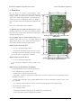
1. Overview
The jrk family of versatile, general-purpose motor
controllers supports a variety of interfaces, including USB.
Analog voltage and tachometer (frequency) feedback
options allow quick implementation of closed-loop servo
systems, and a free configuration utility (for Windows)
allows easy calibration and configuration through the USB
port.
There are two different jrk motor controllers:
The jrk 21v3 [http://www.pololu.com/product/1392] has a broad
operating range from 5 V to 28 V. The continuous output
current of 3 A (5 A peak) allow this board to control most
small DC brushed motors.
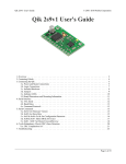
The jrk 12v12 [http://www.pololu.com/product/1393] has an
operating range from 6 V to 16 V. The high continuous
output current of 12 A (30 A peak) allow this board to
control many medium-sized DC brushed motors
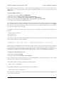
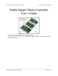
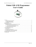
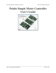
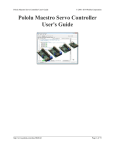
Pololu jrk 21v3 USB motor controller with
dimensions.
Main Features of the Jrk 21v3
• 5 V to 28 V operating supply range.
• 3 A maximum continuous current output (5 A peak).
• Automatic motor driver shutdown on under-voltage,
over-current, and over-temperature conditions.
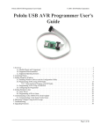
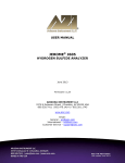
Main Features of the Jrk 12v12
• 6 V to 16 V operating supply range.
Bottom of the jrk 12v12 USB motor controller
with feedback with dimensions.
• 12 A maximum continuous current output (30 A
peak).
Main Features of all Jrk Motor Controllers
• Simple bidirectional control of one DC brush motor.
• Four communication or control options:
◦ USB interface for direct connection to a PC.
◦ Full-duplex, TTL-level asynchronous serial interface for direct connection to microcontrollers or other
embedded controllers.
◦ Hobby radio control (RC) pulse width (PWM) interface for direct connection to an RC receiver or RC
servo controller.
◦ 0–5 V analog voltage interface for direct connection to potentiometers and analog joysticks.
• Two closed-loop feedback options:
◦ 0–5 V analog voltage.
◦ Frequency/tachometer digital input up to 2 MHz with 1 ms PID period.
◦ (Open-loop control with no feedback also available.)
1. Overview
Page 3 of 45
Pololu Jrk USB Motor Controller User's Guide
© 2001–2014 Pololu Corporation
• Simple configuration and calibration over USB with free configuration program (Windows 8, Windows 7,
Vista, Windows XP compatible).
• Configurable parameters include:
◦ PID period and PID constants (feedback tuning parameters).
◦ Maximum current.
◦ Maximum duty cycle.
◦ Maximum acceleration.
◦ Error response.
◦ Input calibration (learning) for analog and RC control.
• Optional CRC error detection eliminates communication errors caused by noise or software faults.
• Reversed power protection.
• Field-upgradeable firmware.
• Optional feedback potentiometer disconnect detection.
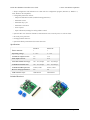
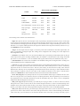
Specifications
_
Jrk 21v3
Jrk 12v12
Motor channels:
1
1
Operating voltage:
5 – 28 V
6 – 16 V
Continuous output current:
3A
12 A
Peak output current:
5A
30 A
Auto-detect baud rate range:
300 – 115,200 bps
300 – 115,200 bps
Available fixed baud rates:
300 – 115,200 bps
300 – 115,200 bps
Available PWM frequencies:
20 kHz, 5 kHz
20 kHz, 5 kHz
Reverse voltage protection?:
Yes
Yes
USB connector style:
USB Mini-B
USB Mini-B
Included Hardware
1. Overview
Page 4 of 45
Pololu Jrk USB Motor Controller User's Guide
© 2001–2014 Pololu Corporation
The jrk 21v3 and jrk 12v12 each ship with a straight 0.1″ breakaway male header [http://www.pololu.com/product/965]
strip and two appropriately sized 2-pin terminal blocks (3.5 mm pitch for the 21v3 and 5 mm pitch for the 12v12). To
provide maximum flexibility, none of these parts are soldered to the board (unless you ordered our fully assembled
jrk 21v3 [http://www.pololu.com/product/1394], which ships with these parts soldered in as shown in the assembled jrk
21v3 picture above).
For the most compact installation, you can solder wires directly to the jrk pads themselves and skip using the included
hardware. The included hardware allows you to make less permanent connections. You can break the header strip into
smaller pieces, such as an 8×1 piece and two 3×1 pieces, and solder these strips into the jrk’s I/O pads.
The three mounting holes are intended for use with #2 screws [http://www.pololu.com/category/101/nuts-and-screws] (not
included).
Note: A USB A to mini-B cable [http://www.pololu.com/product/130] (not included) is required to connect
this device to a computer.
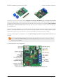
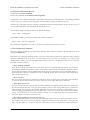
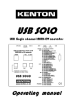
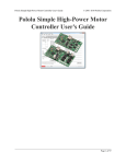
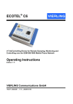
1.a. Module Pinout and Components
Pololu jrk 21v3 USB motor controller with feedback, labeled top view.
1. Overview
Page 5 of 45
Pololu Jrk USB Motor Controller User's Guide
© 2001–2014 Pololu Corporation
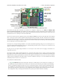
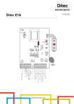
Pololu jrk 12v12 USB motor controller with feedback, labeled top view.
The Pololu jrk USB motor controller can connect to a computer’s USB port via a USB A to mini-B cable
[http://www.pololu.com/product/130] (not included). The USB connection is used to configure the motor controller. It can
also be used to send commands to the motor controller, get information about the motor controller’s current state, and
send and receive TTL serial bytes on the TX and RX lines.
Power for the motor must be supplied to the jrk on the VIN and GND lines pictured on the right side of the diagram
above. Your power source must be capable of delivering the current your motor will draw. The jrk has reverse power
protection on the motor power input lines, so the board will not be damaged if the motor power inputs are accidentally
switched. If the VIN supply is not present, the jrk’s microcontroller can be powered directly from USB and perform
all of its functions except for driving the motor.
For the jrk 21v3, the input voltage should be 5–28 V (the recommended operating voltage is 8–28 V, but the jrk 21v3’s
motor driver has derated performance down to 5 V and transient protection to 40 V). The jrk 21v3’s motor driver can
supply a continuous 3 A with peaks up to 5 A.
For the jrk 12v12, the input voltage should be 6–16 V. The jrk 12v12’s motor driver can supply a continuous 12 A
with peaks up to 30 A.
The jrk has a linear voltage regulator that derives 5 V from the VIN supply. The 5 V supply is used as the internal
logic supply for the jrk and is also available at several pins for powering devices such as external microcontrollers and
feedback sensors (such as potentiometers). Because the regulator must dissipate excess power as heat, the available
output current is dependent on the input voltage: 50 mA is available for VIN up to 12 V; the available current drops
off linearly from 50 mA at 12 V to zero at 30 V.
The jrk has three indicator LEDs:
• The green USB LED indicates the USB status of the device. When the jrk is not connected to a computer via
the USB cable, the green LED will be off. When you connect the jrk to USB, the green LED will start blinking
slowly. The blinking continues until the jrk receives a particular message from the computer indicating that the
jrk’s USB drivers are installed correctly. After the jrk gets this message, the green LED will be on, but it will
flicker briefly when there is USB activity. The configuration utility constantly streams data from the jrk, so when
the configuration utility is running and connected to the jrk, the green LED will flicker constantly.
1. Overview
Page 6 of 45
Pololu Jrk USB Motor Controller User's Guide
© 2001–2014 Pololu Corporation
• The red error LED indicates an error. If there is an error stopping the motor (besides the Awaiting Command
error bit), then the red LED will be on. The red LED is tied to the active-high output ERR, so when there is an
error, ERR will be driven high, and otherwise it will be pulled low through the LED.
• The yellow output status LED indicates the status of the motor. If the yellow LED is off, then an error (other
than the Awaiting Command error bit) is stopping the motor. If the yellow LED is flashing slowly (once per
second), then either the motor is off (the Awaiting Command Error bit is set) or the jrk is in speed control mode
and the duty cycle is zero. If the yellow LED is on solid, then the motor is on and the motor has reached the
desired state. For analog and pulse width feedback modes, this means that the target is within 20 of the scaled
feedback. For speed control mode, this means that the duty cycle equals the duty cycle target. If the yellow LED
is flashing quickly (16 times per second), then the motor is on and the motor has not reached its desired state.
The ERR line is an optional output that is tied to the red error LED described above. It is driven high when the
red LED is on, and it is a pulled low through the red LED when the red LED is off. Since the ERR line is never
driven low, it is safe to connect the ERR line of multiple jrks together. Please note, however, that doing this will cause
the error LEDs of all connected jrks to turn on whenever one jrk experiences an error; the ERR output of the jrk
experiencing the error will drive the LEDs of any other jrks it is connected to, even though they are not experiencing
error conditions themselves. For more information on the possible error conditions and response options, please see
Section 3.f.
The TX line transmits non-inverted, TTL (0 – 5 V) serial bytes. These bytes can either be responses to serial
commands sent to the jrk, or arbitrary bytes sent from the computer via the USB connection. For more information
about the jrk’s serial interface, see Section 4.
The RX line is the jrk’s control input. In serial input mode, the RX line is used to receive non-inverted, TTL (0 –
5 V) serial bytes. These bytes can either be serial commands for the jrk, arbitrary bytes to send back to the computer
via the USB connection, or both. For more information about the jrk’s serial interface, see Section 4. In analog input
mode, RX is the analog input line used to determine the system’s target output. In pulse width input mode, the jrk
measures the duration of pulses on the RX line to determine the system’s target output. Please see Section 3.b for
more information on control input signals.
The FB line is the jrk’s feedback input. In analog feedback mode, the voltage on the FB line is used as a measurement
of the output of the system. In frequency feedback mode, the frequency of low-to-high transitions on the FB line is
used as a measurement of the output of the system. Please see Section 3.c for more information on feedback signals.
The AUX line is an output that is generally high whenever the jrk has power. The line will only go low for two
reasons:
1. If the jrk’s microcontroller goes to sleep (because there is no VIN supply and the device has entered USB
suspend mode), the pin is tri-stated and pulled low through a resistor.
2. If the Detect disconnect with AUX option is enabled for either the feedback or the input, then the jrk will
drive AUX low for about 150 μs each PID period to check if the feedback and/or analog inputs are disconnected.
The RST pin can be driven low to perform a hard reset of the jrk’s microcontroller, but this should generally not be
necessary for typical applications. The line is internally pulled high, so it is safe to leave this pin unconnected.
1.b. Supported Operating Systems
The jrk works under Microsoft Windows 8, Windows 7, Windows Vista, Windows XP, Linux, and Max OS X 10.7 or
later.
The configuration utility works only in Windows, so the jrk must be initially configured from a Windows computer,
but after that it can be controlled from a Linux or Mac computer.
1. Overview
Page 7 of 45
Pololu Jrk USB Motor Controller User's Guide
© 2001–2014 Pololu Corporation
Under Linux, the two virtual COM ports created by the jrk should appear as devices with names like /dev/ttyACM0
and /dev/ttyACM1 (the number depends on how many other ACM devices you have plugged in) and you can use any
terminal program (such as screen) to send and receive bytes on those ports. Alternatively, you can use the Pololu USB
Software Development Kit which supports Linux and has example applications that control the jrk using its native
USB interface (see Section 6).
Under Mac OS X 10.7 or later, the two virtual COM ports created by the jrk should appear as devices with names
like /dev/cu.usbmodem00034567 and you can use any terminal program (such as screen) to send and receive bytes on
those ports.
Mac OS X compatibility: we have confirmed that the jrk works on Mac OS X 10.7 and we can assist
with advanced technical issues, but most of our tech support staff does not use Macs, so basic support
for Mac OS X is limited.
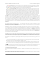
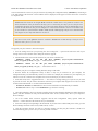
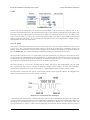
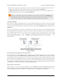
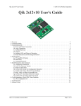
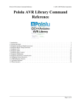
1.c. PID Calculation Overview
The jrk is designed to be part of a control system in which the output (usually a motor position or speed) is constantly
adjusted to match a specified target value. To achieve this, it constantly measures the state of the system and responds
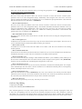
based on the latest information. The information processing performed by the jrk is outlined in the diagram below:
Diagram of a typical feedback system, showing
quantities computed by the jrk.
In this diagram, each arrow represents a specific number measured or computed by the jrk, and the blue boxes
represent the internal computations that each occur once per PID period. The PID period can be set in 1 ms increments
and is one of about 50 configurable parameters that affect the behavior of the system. For more information about
configuring the jrk, see Section 3. The jrk uses the following measurements to determine the output:
• The input is measured as a value from 0 to 4095. In analog voltage input mode, this represents a voltage level
of 0 to 5 V. In RC mode, the number is a pulse width in units of 2/3 μs. The input is adjusted according to input
scaling parameters to determine the target, also a value from 0 to 4095 (see Section 3.b).
1. Overview
Page 8 of 45
Pololu Jrk USB Motor Controller User's Guide
© 2001–2014 Pololu Corporation
• The feedback is measured as a value from 0 to 4095. In analog voltage feedback mode, this represents a
voltage level of 0 to 5 V. In digital frequency mode, it is a representation of the output speed (see Section 3.c.)
The jrk uses this value to compute the scaled feedback, which is a representation of the output of the entire
control system. A scaled feedback of 0 should represent the minimum position of the system, and 4095 should
represent the maximum position.
• The current through the motor is measured as a number from 0 to 255. A calibration value relates this to an
actual current in amps.
Every PID cycle, the jrk performs the following computations to determine the behavior of the motor (see Section
3.d for more information):
1. The error is computed as the difference of scaled feedback and target (error = scaled feedback − target).
2. An implementation of the PID algorithm is applied to the error. PID stands for the three terms that are added
together: proportional (proportional to the error), integral (proportional to the accumulated sum of the error over
time), and derivative (proportional to the difference of the error relative to the previous PID period.) The three
constants of proportionality are the most important parameters determining the behavior of the control system.
The result of the PID algorithm is a number from -600 to +600 called the duty cycle target.
3. The duty cycle target is reduced according to various configurable limits, including acceleration, current, and
maximum duty cycle limits (Section 3.e). The limits are intended to prevent the system from causing damage to
itself under most circumstances.
The resulting value becomes the duty cycle of the PWM (pulse width modulation) signal applied to the motor. A value
of +600 corresponds to 100% duty cycle in the forward direction, a value of -600 corresponds to 100% duty cycle in
the reverse direction, and a value of 0 corresponds to 0% duty cycle or off.
Various parameters and commands have an effect on the steps described above. For example, feedback may be turned
off so that the jrk can become a simple speed controller; in this case the PID calculation is bypassed and the duty
cycle target is just equal to the target minus 2048. In this mode, limits applied to the duty cycle continue to provide a
useful way of preventing damage to the system. As another example, a command to turn the system off prevents the
motors from being driven, but all measurements and calculations continue to occur normally.
1. Overview
Page 9 of 45
Pololu Jrk USB Motor Controller User's Guide
© 2001–2014 Pololu Corporation
2. Contacting Pololu
You can check the Pololu Jrk 21v3 USB Motor Controller page
[http://www.pololu.com/product/1392] or the Pololu Jrk 12v12 USB Motor
Controller page [http://www.pololu.com/product/1393] for additional information.
We would be delighted to hear from you about any of your projects and about
your experience with the jrk. You can contact us [http://www.pololu.com/contact]
directly or post on our forum [http://forum.pololu.com/]. Tell us what we did
well, what we could improve, what you would like to see in the future, or
anything else you would like to say!
2. Contacting Pololu
Page 10 of 45
Pololu Jrk USB Motor Controller User's Guide
© 2001–2014 Pololu Corporation
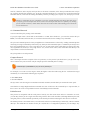
3. Configuring the Motor Controller
3.a. Installing Windows Drivers and the Configuration Utility
If you use Windows XP, you will need to have Service Pack 3 [http://www.microsoft.com/downloads/
details.aspx?FamilyId=68C48DAD-BC34-40BE-8D85-6BB4F56F5110] installed before installing the drivers for
the jrk. See below for details.
Before you connect your Pololu jrk USB motor controller to a computer running Microsoft Windows, you must install
its drivers:
1. Download
the
jrk
drivers and
(5MB zip)
configuration
software
[http://www.pololu.com/file/download/jrk-
windows-121204.zip?file_id=0J221]
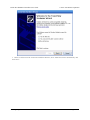
2. Open the ZIP archive and run setup.exe. If the installer fails, you may have to extract all the files to a
temporary directory, right click setup.exe, and select “Run as administrator”. The installer will guide you through
the steps required to install the Pololu Jrk Configuration Utility, the jrk command-line utility (JrkCmd), and the
jrk drivers on your computer.
3. During the installation, Windows will ask you if you want to install the drivers. Click “Install” (Windows 8,
7, and Vista) or “Continue Anyway” (Windows XP).
4. After the installation is finished, your start menu will have a shortcut to the Jrk Configuration Utility (in
the Pololu folder). This is a Windows application that allows you to change all of the settings of your motor
controller, as well as see real-time information about its state.
Windows 8, Windows 7, and Windows Vista users: Your computer should now automatically install the necessary
drivers when you connect a jrk. No further action from you is required.
Windows XP users: Follow steps 5-9 for each new jrk you connect to your computer.
5. Connect the device to your computer’s USB port. The jrk shows up as three devices in one so your XP
computer will detect all three of those new devices and display the “Found New Hardware Wizard” three
times. Each time the “Found New Hardware Wizard” pops up, follow steps 6-9.
6. When the “Found New Hardware Wizard” is displayed, select “No, not this time” and click “Next”.
3. Configuring the Motor Controller
Page 11 of 45
Pololu Jrk USB Motor Controller User's Guide
© 2001–2014 Pololu Corporation
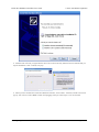
7. On the second screen of the “Found New Hardware Wizard”, select “Install the software automatically” and
click “Next”.
3. Configuring the Motor Controller
Page 12 of 45
Pololu Jrk USB Motor Controller User's Guide
© 2001–2014 Pololu Corporation
8. Windows XP will warn you again that the driver has not been tested by Microsoft and recommend that you
stop the installation. Click “Continue Anyway”.
9. When you have finished the “Found New Hardware Wizard”, click “Finish”. After that, another wizard will
pop up. You will see a total of three wizards when plugging in the jrk. Follow steps 6-9 for each wizard.
3. Configuring the Motor Controller
Page 13 of 45
Pololu Jrk USB Motor Controller User's Guide
© 2001–2014 Pololu Corporation
If you use Windows XP and experience problems installing or using the serial port drivers, the cause of your problems
might be a bug in older versions of Microsoft’s usb-to-serial driver usbser.sys. Versions of this driver prior to version
5.1.2600.2930 will not work with the jrk. You can check what version of this driver you have by looking in the
“Details” tab of the “Properties” window for usbser.sys in C:\Windows\System32\drivers. To get the fixed version
of the driver, you will need to install Service Pack 3 [http://www.microsoft.com/downloads/details.aspx?FamilyId=68C48DADBC34-40BE-8D85-6BB4F56F5110]. If you do not want Service Pack 3, you can try installing Hotfix KB918365 instead, but
some users have had problems with the hotfix that were resolved by upgrading to Service Pack 3. The configuration
utility will work even if the serial port drivers are not installed properly.
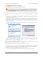
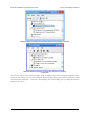
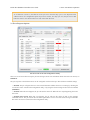
After installing the drivers, if you go to your computer’s Device Manager and expand the “Ports (COM & LPT)” list,
you should see two COM ports: the Command Port and the TTL Port. In parentheses after these names, you will see
the name of the port (e.g. “COM5” or “COM6”). If you expand the “Pololu USB Devices” list you should see an
entry for the Pololu jrk motor controller.
3. Configuring the Motor Controller
Page 14 of 45
Pololu Jrk USB Motor Controller User's Guide
© 2001–2014 Pololu Corporation
Windows 8 device manager showing the Pololu Jrk 21v3 Motor Controller
Windows XP device manager showing the Pololu Jrk 21v3 Motor
Controller
Some software will not allow connection to higher COM port numbers. If you need to change the COM port number
assigned to your USB device, you can do so using the Device Manager. Bring up the properties dialog for the COM
port and click the “Advanced…” button in the “Port Settings” tab. From this dialog you can change the COM port
assigned to your device.
3. Configuring the Motor Controller
Page 15 of 45
Pololu Jrk USB Motor Controller User's Guide
© 2001–2014 Pololu Corporation
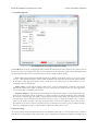
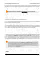
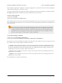
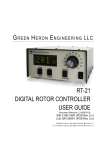
3.b. Input Options
The Input tab of the Jrk Configuration Utility
The Input tab of the jrk configuration utility contains settings for how the feedback system (consisting of the jrk, a
motor and a feedback sensor) is externally controlled and monitored. Most importantly, there are three Input modes:
• Serial indicates that the jrk gets its target setting over a serial interface, either a virtual COM port or the TTLlevel serial port of the jrk, as explained in detail in Section 4.
• Analog voltage is used when an analog voltage source, such as a potentiometer, connected to the RX line is
used to set the target. A signal level of 0 V on this line corresponds to an input value of 0, and signal level of 5 V
correponds to an input value of 4092.
• Pulse width is used when the system is to be controlled by the width of digital pulses, such as those output
by a radio-control (RC) receiver, measured on the RX line. In this input mode, the input value is the width of
the most recent pulse, in units of 2/3 μs. For example, a pulse width of 1500 μs corresponds to an input value
of 2250. This input interface accepts pulses from 400 to 2600 μs at a frequency between 10 and 150 Hz. The
jrk will only update the input value if it has received four valid pulses in a row, and it will generate the Input
invalid error if it goes more than 120 ms without updating the input value. The voltage of the high pulses must
be between 2 and 5 V.
Version 1.3 of the firmware for the Jrk 21v3 and the Jrk 12v12 contains a bug fix that improves the
reliability of the Pulse width input. The update is recommended for devices with an earlier firmware
version number, including all devices shipped before August 25, 2009. See Section 3.h for upgrade
information.
3. Configuring the Motor Controller
Page 16 of 45
Pololu Jrk USB Motor Controller User's Guide
© 2001–2014 Pololu Corporation
Input scaling
The scaling options in this tab determine how the raw input values map to target values, which determine the output
of the system. The parameters Maximum and Minimum should be set to the maximum and minimum possible values
of the input device; these will be scaled to the target values specified in the right column. For input devices with a
clearly defined neutral position, such as joysticks, parameters Neutral Max and Neutral Min are provided. Any input
between Neutral Max and Neutral Min will be scaled to the neutral value specified in the right column. Setting the
two neutral values to be different allows for a “dead zone”, which is especially desirable in speed control mode. If
the input leaves the range specified by the Absolute Max and Absolute Min parameters, an Input disconnect error will
occur. For convenience, the Invert input direction option is provided. Select this option to switch the positive and
negative input directions.
By default, the scaling is linear, but you can change the Degree parameter to use a higher-degree polynomial function,
which gives you better control near the neutral point.
Clicking the button labeled “Learn…” allows scaling values to be determined automatically: with the motor off,
the program will request that the input be set to its minimum, maximum, and neutral positions, and the resulting
values will be recorded. After learning, if the neutral position is not important for your system, you may uncheck
“Asymmetric” to automatically center the neutral values between minimum and maximum.
Input analog to digital conversion
In analog mode, the analog to digital conversion panel lets you specify the number of analog samples to average
together each PID cycle, which determines the precision and speed of the analog to digitial conversions. The indicator
labeled “PID period exceeded” at the top of the window is provided as a warning for when the analog sampling takes
more time than the specified PID period.
Selecting the Detect disconnect with AUX option activates an extra feature that allows the jrk to detect if the RX pin
becomes disconnected from the analog voltage input device or shorted to 5 V. This option is intended for use in analog
voltage input mode with a potentiometer connected between AUX and ground. When the option is selected, the jrk
will periodically drive the AUX pin low, verifying that this results in a 0 V signal at RX. If the line does not respond
as expected, the Input disconnect error will occur.
Serial interface
This panel allows the serial ports of the jrk to be configured, including specifying a fixed baud rate and enabling or
disabling a CRC byte for all commands. The Device Number setting is useful when using the jrk with other devices in
a daisy-chained configuration, and the Timeout specifies the duration before which a Serial timeout error will occur
(a Timeout of 0.00 disables the serial timeout feature).
For more details on the serial interface, especially for selecting the appropriate mode for your system, see Section
4.a.
Manually set target (serial mode only)
This section is provided for debugging and testing systems without using an input device. The target may be specified
directly with the scrollbar or numerical input.
3. Configuring the Motor Controller
Page 17 of 45
Pololu Jrk USB Motor Controller User's Guide
© 2001–2014 Pololu Corporation
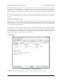
3.c. Feedback Options
The Feedback tab of the Jrk Configuration Utility
The Feedback tab of the jrk configuration utility controls the measurements of the output of the control system. If
this section is properly configured, the value of scaled feedback will be 0 when the output is at the minimum position
and 4095 when the output is at its maximum. There are three available feedback modes:
• None indicates that feedback and the PID calculation are disabled. In this mode, the duty cycle target is equal
to target − 2048 instead of being the result of a PID calculation. This means that a target of 2648 will correspond
to driving the motor full speed forward, 2048 is brake, and so on. However, the jrk still performs all of its
calculations once per “PID period”.
• Analog voltage is used when an analog voltage source, such as a potentiometer, connected to the FB pin
indicates the position of the output. A signal level of 0 V corresponds to a feedback value of 0, and a signal level
of 5 V corresponds to a feedback value of 4092.
• Frequency (digital) is used with speed-measuring devices that generate pulses at a rate proportional to the
speed of the output shaft, such as a tachometer. A simple example is an optical breakbeam sensor measuring
the rotation of a slotted disk. The number of pulses detected on the FB pin during each PID period is used as
a measurement of speed. When driving the motor forward (i.e. target > 2048), the feedback value is 2048+n,
where n is the number of pulses, and when driving the motor in reverse, the feedback value is 2048-n. Since
the feedback value must be between 0 and 4095, the jrk can measure at most 2047 pulses per PID period. This
allows for a maximum frequency of approximately 2 MHz with a PID period of 1 ms.
Feedback scaling
The scaling options in this tab determine how the raw feedback values map to scaled feedback values, which are
intended to be a representation of the output of the system. The parameters Maximum and Minimum should be set to
3. Configuring the Motor Controller
Page 18 of 45
Pololu Jrk USB Motor Controller User's Guide
© 2001–2014 Pololu Corporation
the maximum and minimum possible values of the output; these will be converted to scaled feedback values of 4095
and 0, respectively. If the feedback leaves the range specified by the Absolute Max and Absolute Min parameters, a
Feedback disconnect error will occur. For convenience, the Invert feedback direction option is provided. Select this
option if the direction of motion that you would like to call positive actually results in a decreasing feedback value.
Clicking the button labeled “Learn…” allows scaling values to be determined automatically: with the motor off,
the program will request that the output be moved to its minimum and maximum, and the resulting values will be
recorded.
Input analog to digital conversion
In analog mode, the analog to digital conversion panel lets you specify the number of analog samples to average
together each PID cycle, which determines the precision and speed of the analog to digital conversions. The indicator
labeled “PID period exceeded” at the top of the window is provided as a warning for when the analog sampling takes
more time than the specified PID period.
Selecting the Detect disconnect with AUX option activates an extra feature that allows the jrk to detect if the FB pin
becomes disconnected from the analog voltage input device or shorted to 5 V. This option is intended for use in analog
voltage feedback mode with a potentiometer connected between AUX and ground. When the option is selected, the
jrk will periodically drive the AUX pin low, verifying that this results in a 0 V signal at FB. If the line does not
respond as expected the Feedback disconnect error will occur.
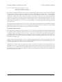
3.d. PID Options
The PID tab of the Jrk Configuration Utility
The PID tab of the jrk configuration utility controls the central calculation performed by the jrk:
3. Configuring the Motor Controller
Page 19 of 45
Pololu Jrk USB Motor Controller User's Guide
© 2001–2014 Pololu Corporation
duty cycle target =(Proportional coefficient) × error
+ (Integral coefficient) × integral
+ (Derivative coefficient) × derivative
The integral is computed as the sum of the error over all PID cycles, and the derivative is the current error minus
the previous error. The error itself is the difference of the scaled feedback and the target (error = scaled feedback
– target). Each of the PID coefficients is specified as an integer value divided by a power of two. The proportional
and derivative coefficients can have values from 0.00003 to 1024, and any value above 0.0152 can be approximated
within 0.5%. To get the closest approximation to a desired value, type the number into the box after the equal sign,
and the best possible numerator and denominator will be computed. In the case of the integral coefficient, the range
of the denominator is actually 23 to 218; this is a more useful range, since the integral is usually much larger than the
error or derivative.
The PID period can be adjusted here; this sets the rate at which the jrk runs through all of its calculations. Note that a
higher PID period will result in a more slowly changing integral and a higher derivative, so that the two corresponding
PID constants might need to be adjusted whenever the PID period is changed.
Preventing integral wind-up
Three options are provided for limiting “integral wind-up”, which is the uncontrolled growth of the integral when
the feedback system is temporarily unable to keep the error small. This might happen, for example, when the target
is changing quickly. One option is the integral limit, a value from 0 to 32767 that simply limits the magnitude of
the integral. Note that the maximum value of the integral term can be computed as the integral coefficient times the
integral limit: if this is very small compared to 600 (maximum duty cycle), the integral term will have at most a very
small effect on the duty cycle.
Another option causes the integral to reset to 0 when the proportional term exceeds the maximum duty cycle
parameter. For example, if this option is selected when the proportional coefficient is 15 and the maximum duty cycle
is 300, the integral will reset whenever the error is larger than 20.
Additionally the Feedback dead zone option sets the duty cycle target to zero and resets the integral whenever the
magnitude of the error is smaller than this amount. This is useful for preventing the motor from driving when the
target is very close to scaled feedback. The feedback dead zone uses hysteresis to keep the system from simply riding
the edge of the dead zone; once in the dead zone, the duty cycle and integral will remain zero until the magnitude of
the error exceeds twice this value.
3. Configuring the Motor Controller
Page 20 of 45
Pololu Jrk USB Motor Controller User's Guide
© 2001–2014 Pololu Corporation
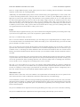
3.e. Motor Options
The Motor tab of the Jrk Configuration Utility
The Motor tab of the jrk configuration utility controls the PWM [http://en.wikipedia.org/wiki/Pulse-width_modulation]
signal applied to the motor, including all limits that are applied when converting duty cycle target to duty cycle.
The jrk’s PWM duty cycle has a range of -600 to 600, where -600 is full reverse and 600 is full forward. “Forward”
and “reverse” should be consistent with the scaled feedback values, so that when the duty cycle is positive, the motor
spins in a direction that increases the scaled feedback. By default, full forward (+600) means motor output A = VIN
and B = 0 V, while full reverse (-600) means A = 0 V and B = VIN. When checked, the Invert motor direction option
switches these definitions so that full forward (+600) means A = 0 V and B = VIN, while full reverse (-600) means A
= VIN and B = 0 V.
Detect motor direction
To automatically detect whether the motor is inverted or not, click “Detect Motor Direction”. This will attempt to
drive the motor with a gradually increasing duty cycle until it starts to move, as measured by the feedback. Make sure
to configure feedback correctly before clicking this button, or the results will be meaningless. It is also recommended
to set up low maximum duty cycles and currents, and set the Motor drive error, Feedback disconnect, and Max.
current exceeded errors to be “Enabled and latched”, so that any potentially damaging conditions encountered during
this test will cause the jrk to turn off the motor.
PWM frequency
The jrk is capable of both 20 kHz and 5 kHz PWM. The 20 kHz PWM frequency is ultrasonic and can thus eliminate
audible PWM-induced motor humming, which makes this frequency desirable for typical applications.
3. Configuring the Motor Controller
Page 21 of 45
Pololu Jrk USB Motor Controller User's Guide
© 2001–2014 Pololu Corporation
However, a higher PWM frequency means greater power loss due to switching, which could make a 5 kHz PWM
frequency a better choice for certain applications.
Additionally, the 5 kHz PWM frequency allows for finer control at duty cycles approaching 0% or 100% (±600). This
is because the timing characteristics of the jrk motor drivers make it so that very short PWM pulses (either low or
high) have no effect on the output voltage. This limitation is more pronounced on the jrk 21v3, in which pulses that
are shorter than approximately 4 μs have no effect on the output voltage. Therefore, at 20 kHz, the jrk 21v3 with a
duty cycle less than 8% will effectively have a duty cycle of 0% (braking), while a duty cycle greater than 92% will
be the same as a duty cycle of 100% (the jrk 12v12 can typically go a bit closer to 0% and 100%). At 5 kHz, the effect
is smaller by a factor of four: a duty cycle less than 2% will be the same as a duty cycle of 0% (braking) while a duty
cycle greater than 98% will be the same as a duty cycle of 100%.
Limits
Various limits may be applied to the duty cycle, each of which can be configured separately for forward (positive duty
cycle) and reverse (negative duty cycle) if the “Asymmetric” option is checked:
Max. duty cycle limits the duty cycle itself.
Max. acceleration limits the amount that the duty cycle can change by in a single PID period. For example, if there
is an acceleration limit of 10 in both directions, and the current duty cycle is 300, then the duty cycle in the next PID
period is limited to be within -10 to 310.
Max. current causes the jrk to measure the motor driver current and adjust the duty cycle as necessary to limit it the
specified value. The current is reported as a number from 0 to 255 that is multiplied by the Current calibration to get
a number in mA, so increasing the current calibration value will increase the measured value. For accurate current
limiting, acceleration should be limited; otherwise the duty cycle will tend to oscillate when the maximum current is
exceeded.
Brake duration is a feature that is most useful for large motors with high-inertia loads used with frequency feedback
or speed control mode (no feedback). If this option is used, the jrk will automatically keep the motor at a duty cycle
of 0 for the specified time before switching directions. The “forward” setting refers to switching from forward to
reverse, and the “reverse” setting refers to switching from reverse to forward.
Max. duty cycle while feedback is out of range is an option to limit possible damage to systems by reducing the
maximum duty cycle whenever the feedback value is beyond the absolute minimum and maximum values. This can
be used, for example, to slowly bring a system back into its valid range of operation when it is dangerously near a
limit. The Feedback disconnect error should be disabled when this option is used.
When motor is off
When the motor is off because of an error condition or an explicit Motor Off command, there are two options for the
state of the motor driver: brake (A and B both connected to GND) and coast (A and B floating).
You can familiarize yourself with motor coasting and braking using nothing more than a motor. First, with your motor
disconnected from anything, try rotating the output shaft and note how easily it turns. Then hold the two motor leads
together and try rotating the output shaft again. You should notice significantly more turning resistance while the
leads are shorted together.
The jrk 21v3 PWMs the motor outputs between driving and braking, and a duty cycle of zero is the same as braking.
The jrk 12v12 PWMs the motor outputs between driving and coasting when the duty cycle is non-zero.
3. Configuring the Motor Controller
Page 22 of 45
Pololu Jrk USB Motor Controller User's Guide
© 2001–2014 Pololu Corporation
As of firmware version 1.4, the behavior of the jrk 12v12 when the duty cycle is zero depends on the
“When motor is off” configuration option. In previous versions, at a duty cycle of 0, the jrk 12v12 would
brake the motor in one direction but let it coast in the other direction.
3.f. Error Response Options
The Errors tab of the Jrk Configuration Utility
There are several errors that can stop the jrk from driving its motor. For information about what each error means, see
Section 4.f.
The jrk’s response to the different errors can be configured. Each error has up to three different available settings.
• Disabled: The jrk will ignore this error. You can still determine whether the error is occurring by checking the
“Occurrence count” column in the configuration utility, or by using the Get Error Flags Occurred serial command
(Section 4.f).
• Enabled: When this error happens, the jrk will turn the motor off. When the error stops happening, the motor
can restart.
• Enabled and Latched: When this error happens, the jrk will turn the motor off and set the Awaiting
Command error bit. The jrk will not drive the motor again until it receives one of the serial set target commands.
The motor can also be restarted from the configuration utility.
3. Configuring the Motor Controller
Page 23 of 45
Pololu Jrk USB Motor Controller User's Guide
© 2001–2014 Pololu Corporation
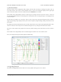
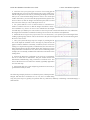
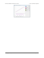
3.g. The Plots Window
The Plots window of the configuration utility displays real-time data from the jrk, scrolling from right to left. To
access this window, select “Plots” from the Window menu, or click on the small plot displayed in the upper-right
corner of the main window. All of the variables discussed in Section 1.c are available.
Each variable can be independently scaled to a useful range. For example, the Error can be from -4095 to +4095, but
for well-tuned feedback systems, it will usually have a much smaller value, so setting the range to ±100 might provide
a more useful plot.
The plot shows all variables on a scale from -100% to 100%, where 100% represents the high end of the variable’s
range. The percentage range displayed on the plot can also be adjusted, using the Range settings at the bottom of the
plot window.
By default, the plot shows data from the past 5 seconds, with the most recent values on the right and the older values
on the left. The time scale of the plot can be shortened using the Time (s) setting at the bottom of the window.
The color of each variable in the graph can be selected by double clicking on the colored box next to the variable’s
name.
Each variable can be independently shown or hidden using the checkbox next to the variable’s name.
Here is an example showing all variables plotted simultaneously:
3.h. Upgrading Firmware
The jrk has field-upgradeable firmware that can be easily updated with bug fixes or new features.
3. Configuring the Motor Controller
Page 24 of 45
Pololu Jrk USB Motor Controller User's Guide
© 2001–2014 Pololu Corporation
You can determine the version of your jrk’s firmware by running the configuration utility (Section 3.a), connecting to
a jrk, and looking at the firmware version number which is displayed in the upper left corner below the “Connected
to” dropdown box.
Version 1.4 of the firmware for the jrk 12v12 extends the “When motor is off” parameter so that it now
affects the behavior of the jrk whenever the duty cycle is 0. Previously, at a duty cycle of 0, the jrk 12v12
would brake the motor in one direction but let it coast in the other direction. Now the default behavior is
to brake in both directions, but you can configure it to coast instead. Firmware version 1.4 also makes the
jrk 12v12 brake low (connect both A and B to GND) instead of braking high. All jrk 12v12s manufactured
after August 24, 2012 ship with firmware version 1.4.
The latest version of the jrk 21v3 firmware available is Version 1.3. Do not attempt to load jrk 12v12
firmware onto a jrk 21v3, or vice-versa.
To upgrade your jrk’s firmware, follow these steps:
1. Save the settings stored on your jrk using the “Save settings file…” option in the File menu. All of your
settings will be reset to default values during the firmware upgrade.
2. Download the latest version of the firmware for your motor controller here:
◦ Firmware version 1.3 for the jrk 21v3 (umc01a) [http://www.pololu.com/file/download/
umc01a_v1.3.pgm?file_id=0J223] (35k pgm) — released 2009-08-25.
◦ Firmware
version
1.4 for the jrk 12v12 (umc02a)
(34k pgm) — released 2012-08-15.
[http://www.pololu.com/file/download/
umc02a_v1.4.pgm?file_id=0J573]
3. Connect your jrk to a computer running Windows using a USB cable.
4. Run the Pololu Jrk Configuration Utility. If there is only one jrk connected to your computer, the
configuration utility will automatically connect to it. If there are multiple jrks connected to your computer, you
will have to use the “Connected to” dropdown box to select which jrk you want to connect to.
5. In the File menu, select “Upgrade Firmware…”. You will see a message asking you if you are sure you want
to proceed: click Yes. The jrk will now disconnect itself from your computer and reappear as a new device called
“Pololu umc01a Bootloader” or “Pololu umc02a Bootloader”.
◦ Windows 8, Windows 7, and Vista: the driver for the bootloader will automatically be installed.
◦ Windows XP: follow steps 6-8 from Section 3.a to get the driver working.
6. Once the bootloader’s drivers are properly installed, the green LED should be blinking in a double heart-beat
pattern, and there should be an entry for the bootloader in the “Ports (COM & LPT)” list of your computer’s
Device Manager.
7. Go to the window titled “Firmware Upgrade” that the Jrk Configuration Utility opened. Click the
“Browse…” button and select the firmware file you downloaded.
8. Select the COM port corresponding to the bootloader. If you don’t know which COM port to select, go to the
Device Manager and look in the “Ports (COM & LPT)” section.
9. Click the “Program” button. You will see a message warning you that your jrk’s firmware is about to be
erased and asking you if you are sure you want to proceed: click Yes.
3. Configuring the Motor Controller
Page 25 of 45
Pololu Jrk USB Motor Controller User's Guide
© 2001–2014 Pololu Corporation
10. It will take a few seconds to erase the jrk’s existing firmware and load the new firmware. Do not disconnect
the jrk during the upgrade.
11. Once the upgrade is complete, the Firmware Upgrade window will close, the jrk will disconnect from your
computer once again, and it will reappear as it was before. If there is only one Jrk plugged in to your computer,
the Pololu Jrk Configuration Utility will connect to it. Check the firmware version number and make sure that it
now indicates the latest version of the firmware.
If you run into problems during a firmware upgrade, please contact us [http://www.pololu.com/contact] for assistance.
3. Configuring the Motor Controller
Page 26 of 45
Pololu Jrk USB Motor Controller User's Guide
© 2001–2014 Pololu Corporation
4. Using the Serial Interface
4.a. Serial Modes
The jrk has three different serial interfaces. First, it has the RX and TX lines. The jrk can send bytes on the TX line.
If the jrk is in serial input mode, the RX line can be used to receive non-inverted, TTL (0 – 5 V) serial bytes (Section
4.b). If the jrk is not in serial input mode, it can not receive bytes on RX because the line is used for analog voltage or
pulse width measurement. Secondly, the jrk shows up as two virtual serial ports on a computer if it is connected via
USB. One of these ports is called the Command Port and the other is called the TTL port. You can determine the
COM port numbers of these ports by looking in your computer’s Device Manager. See Section 3.a for information.
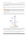
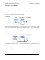
The jrk can be configured to be in one of three basic serial modes:
USB Dual Port
The USB Dual Port serial mode.
In this mode, the Command Port can be used to send commands to the jrk and receive responses from it. The baud
rate you set in your terminal program when opening the Command Port is irrelevant. The TTL Port can be used to
send bytes on the TX line and (if the jrk is in serial input mode) receive bytes on the RX line. The baud rate you
set in your terminal program when opening the TTL Port determines the baud rate used to receive and send bytes on
RX and TX. This allows your computer to control the jrk and simultaneously use the RX and TX lines as a general
purpose serial port that can communicate with other types of TTL serial devices.
USB Chained
The USB Chained serial mode.
In this mode, the Command Port is used to both transmit bytes on the TX line and send commands to the jrk. The
jrk’s responses to those commands will be sent to the Command Port but not the TX line. If the input mode is serial,
bytes received on the RX line will be sent to the Command Port but will not be interpreted as command bytes by the
jrk. The baud rate you set in your terminal program when opening the Command Port determines the baud rate used
to receive and send bytes on RX and TX. The TTL Port is not used. This mode allows a single COM port on your
computer to control multiple jrks, or a jrk and other devices that have a compatible protocol.
4. Using the Serial Interface
Page 27 of 45
Pololu Jrk USB Motor Controller User's Guide
© 2001–2014 Pololu Corporation
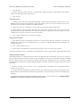
UART
The UART serial mode.
In this mode, the TX and RX lines can be used to send commands to the jrk and receive responses from it. Any
byte received on RX will be sent to the Command Port, but bytes sent from the Command Port will be ignored. The
TTL Port is not used. The baud rate on TX and RX can either be automatically detected by the jrk when a 0xAA
byte is received on RX, or it can be set to a fixed value ahead of time. This mode is only available when the input
mode is serial. This mode allows you to control the jrk (and send bytes to a serial program on the computer) using a
microcontroller or other TTL serial device.
4.b. TTL Serial
If the jrk is in serial input mode, then its serial receive line, RX, can receive bytes when connected to a logic-level (0
to 4.0–5 V, or “TTL”), non-inverted serial signal. The bytes sent to the jrk on RX can be commands to the jrk or an
arbitrary stream of data that the jrk passes on to a computer via the USB port, depending on which Serial Mode the
jrk is in (Section 4.a). The voltage on the RX pin should not go below 0 V and should not exceed 5 V.
The jrk provides logic-level (0 to 5 V) serial output on its serial transmit line, TX. The bytes sent by the jrk on TX
can be responses to commands that request information or an arbitrary stream of data that the jrk is receiving from
a computer the USB port and passing on, depending on which Serial Mode the jrk is in. If you aren’t interested in
receiving TTL serial bytes from the jrk, you can leave the TX line disconnected.
The serial interface is asynchronous, meaning that the sender and receiver each independently time the serial
bits. Asynchronous TTL serial is available as hardware modules called “UARTs” on many microcontrollers.
Asynchronous serial output can also be “bit-banged” by a standard digital output line under software control.
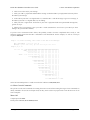
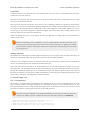
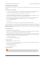
The data format is 8 data bits, one stop bit, with no parity, which is often expressed as 8-N-1. The diagram below
depicts a typical asynchronous, non-inverted TTL serial byte:
Diagram of a non-inverted TTL serial byte.
A non-inverted TTL serial line has a default (non-active) state of high. A transmitted byte begins with a single low
“start bit”, followed by the bits of the byte, least-significant bit (LSB) first. Logical ones are transmitted as high (Vcc)
and logical zeros are transmitted as low (0 V), which is why this format is referred to as “non-inverted” serial. The
byte is terminated by a “stop bit”, which is the line going high for at least one bit time. Because each byte requires a
4. Using the Serial Interface
Page 28 of 45
Pololu Jrk USB Motor Controller User's Guide
© 2001–2014 Pololu Corporation
start bit, 8 data bits, and a stop bit, each byte takes 10 bit times to transmit, so the fastest possible data rate in bytes
per second is the baud rate divided by ten. At the jrk’s maximum baud rate of 115,200 bits per second, the maximum
realizable data rate, with a start bit coming immediately after the preceding byte’s stop bit, is 11,520 bytes per second.
Whenever connecting devices, remember to wire the grounds together, and ensure that each device
is properly powered. Unpowered devices with a TTL serial port can turn on or partially on, drawing
power from the serial line, which means that extra care must be taken when turning power off and on
to reset the devices.
4.c. Command Protocols
You can control the jrk by issuing serial commands.
If your jrk’s input mode is Serial and its Serial Mode is “UART, detect baud rate”, you must first send it the byte
0xAA (170 in decimal) on the RX line (so it can detect the baud rate) before sending it any commands.
The jrk serial command protocol is fairly straightforward. Communication is achieved by sending command packets
consisting of a single command byte followed by any data bytes that command requires. Command bytes always have
their most significant bits set (i.e. they range from 128–255, or 0x80–0xFF in hex) while data bytes always have their
most significant bits cleared (i.e. they range from 0–127, or 0x00–0x7F in hex). This means that each data byte can
only transmit seven bits of information.
The jrk responds to two sub-protocols:
Compact Protocol
This is the simpler and more compact of the two protocols; it is the protocol you should use if your jrk is the only
device connected to your serial line. The jrk compact protocol command packet is simply:
command byte (with MSB set), any necessary data bytes
For example, if we want to set the target to 4080 (the highest value achievable using the low resolution Set Target
commands), we could send the following byte sequence:
in hex: 0xE1, 0x7F
in decimal: 225, 127
The byte 0xE1 is the Set Target Low Resolution Forward command, and the data byte contains the motor speed.
Note that the Set Target High Resolution command uses some of the bits in the command byte to represent data, so
there is not a one-to-one correspondence between command bytes and commands.
Pololu Protocol
This protocol is compatible with the serial protocol used by our other serial motor and servo controllers. As such,
you can daisy-chain a jrk on a single serial line along with our other serial controllers (including additional jrks) and,
using this protocol, send commands specifically to the desired jrk without confusing the other devices on the line.
The Pololu protocol is to transmit 0xAA (170 in decimal) as the first (command) byte, followed by a Device Number
data byte. The default Device Number for the jrk is 11, but this is a configuration parameter you can change. Any
4. Using the Serial Interface
Page 29 of 45
Pololu Jrk USB Motor Controller User's Guide
© 2001–2014 Pololu Corporation
jrk on the line whose device number matches the specified device number accepts the command that follows; all
other Pololu devices ignore the command. The remaining bytes in the command packet are the same as the compact
protocol command packet you would send, with one key difference: the compact protocol command byte is now a
data byte for the command 0xAA and hence must have its most significant bit cleared. Therefore, the command
packet is:
0xAA, device number byte, command byte with MSB cleared, any necessary data bytes
For example, if we want to set the target to 4080 for a jrk with device number 11, we could send the following byte
sequence:
in hex: 0xAA, 0x0B, 0x61, 0x7F
in decimal: 170, 11, 97, 127
Note that 0x61 is the command 0xE1 with its most significant bit cleared.
The jrk responds to both the Pololu and Compact protocols on the fly; you do not need to use a configuration
parameter to identify which protocol you are using.
4.d. Cyclic Redundancy Check (CRC) Error Detection
For certain applications, verifying the integrity of the data you are sending and receiving can be very important.
Because of this, the jrk has optional 7-bit cyclic redundancy checking, which is similar to a checksum but more robust
as it can detect errors that would not affect a checksum, such as an extra zero byte or bytes out of order.
Cyclic redundancy checking can be enabled by checking the “Enable CRC” checkbox in the configuration utility. In
CRC mode, the jrk expects an extra byte to be added onto the end of every command packet. The most-significant bit
of this byte must be cleared, and the seven least-significant bits must be the 7-bit CRC for that packet. If this CRC
byte is incorrect, the jrk will generate its Serial CRC error and ignore the command. The jrk does not append a CRC
byte to the data it transmits in response to serial commands.
A detailed account of how cyclic redundancy checking works is beyond the scope of this document, but you can find
a wealth of information using Wikipedia [http://en.wikipedia.org/wiki/Cyclic_redundancy_check]. The CRC computation is
basically a carryless long division of a CRC “polynomial”, 0x91, into your message (expressed as a continuous stream
of bits), where all you care about is the remainder. The jrk uses CRC-7, which means it uses an 8-bit polynomial and,
as a result, produces a 7-bit remainder. This remainder is the lower 7 bits of the CRC byte you tack onto the end of
your command packets.
The CRC implemented on the jrk is the same as the one on the qik [http://www.pololu.com/product/1110]
motor controller but differs from that on the TReX [http://www.pololu.com/product/777] motor controller.
Instead of being done MSB first, the computation is performed LSB first to match the order in which
the bits are transmitted over the serial line. In standard binary notation, the number 0x91 is written as
10010001. However, the bits are transmitted in this order: 1, 0, 0, 0, 1, 0, 0, 1, so we will write it as
10001001 to carry out the computation below.
The CRC-7 algorithm is as follows:
1. Express your 8-bit CRC-7 polynomial and message in binary, LSB first. The polynomial 0x91 is written as
10001001.
4. Using the Serial Interface
Page 30 of 45
Pololu Jrk USB Motor Controller User's Guide
© 2001–2014 Pololu Corporation
2. Add 7 zeros to the end of your message.
3. Write your CRC-7 polynomial underneath the message so that the LSB of your polynomial is directly below
the LSB of your message.
4. If the LSB of your CRC-7 is aligned under a 1, XOR the CRC-7 with the message to get a new message; if
the LSB of your CRC-7 is aligned under a 0, do nothing.
5. Shift your CRC-7 right one bit. If all 8 bits of your CRC-7 polynomial still line up underneath message bits,
go back to step 4.
6. What’s left of your message is now your CRC-7 result (transmit these seven bits as your CRC byte when
talking to the jrk with CRC enabled).
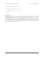
If you have never encountered CRCs before, this probably sounds a lot more complicated than it really is. The
following example shows that the CRC-7 calculation is not that difficult. For the example, we will use a two-byte
sequence: 0x83, 0x01.
Steps 1 & 2 (write as binary, add 7 zeros to the end of the message):
CRC-7 Polynomial = [1 0 0 0 1 0 0 1]
message = [1 1 0 0 0 0 0 1] [1 0 0 0 0 0 0 0] 0 0 0 0 0 0 0
Steps 3, 4, & 5:
_______________________________________________
1 0 0 0 1 0 0 1 ) 1 1 0 0 0 0 0 1 1 0 0 0 0 0 0 0 0 0 0 0 0 0 0
XOR 1 0 0 0 1 0 0 1 | | | | | | | | | | | | | | |
--------------- | | | | | | | | | | | | | | |
1 0 0 1 0 0 0 1 | | | | | | | | | | | | | |
shift ----> 1 0 0 0 1 0 0 1 | | | | | | | | | | | | | |
_______________ | | | | | | | | | | | | | |
1 1 0 0 0 0 0 0 | | | | | | | | | | |
1 0 0 0 1 0 0 1 | | | | | | | | | | |
_______________ | | | | | | | | | | |
1 0 0 1 0 0 1 0 | | | | | | | | | |
1 0 0 0 1 0 0 1 | | | | | | | | | |
_______________ | | | | | | | | | |
1 1 0 1 1 0 0 0 | | | | | | |
1 0 0 0 1 0 0 1 | | | | | | |
_______________ | | | | | | |
1 0 1 0 0 0 1 0 | | | | | |
1 0 0 0 1 0 0 1 | | | | | |
_______________ | | | | | |
1 0 1 0 1 1 0 0 | | | |
1 0 0 0 1 0 0 1 | | | |
_______________ | | | |
1 0 0 1 0 1 0 0 | |
1 0 0 0 1 0 0 1 | |
_______________ | |
1 1 1 0 1 0 0 = 0x17
So the full command packet we would send with CRC enabled is: 0x83, 0x01, 0x17.
4.e. Motor Control Commands
The jrk has several serial commands for turning the motor on and off and setting the target. These commands are
mainly intended to be used in serial input mode, but they can be used in any input mode to turn the motor on or off
from a computer.
Motor Off
Compact protocol: 0xFF
Pololu protocol: 0xAA, device number, 0x7F
4. Using the Serial Interface
Page 31 of 45
Pololu Jrk USB Motor Controller User's Guide
© 2001–2014 Pololu Corporation
This command will turn the motor off by setting the Awaiting Command error bit. The jrk will not restart the motor
until it receives a Set Target command. The jrk can be configured to either brake or coast while the motor is off
(Section 3.e).
Set Target High Resolution
Compact protocol, binary: 110LLLLL, 0HHHHHHH
Compact protocol, hex: 0xC0 + target low 5 bits, target high 7 bits
Pololu protocol, binary: 10101010, device number, 010LLLLL, 0HHHHHHH
Pololu protocol, hex: 0xAA, device number, 0x40 + target low 5 bits, target high 7 bits
(where target is the 12-bit number HHHHHHHLLLLL)
This command clears the Awaiting Command error bit and (if Input Mode is Serial) lets you set the 12-bit target to
any of its allowed values (0–4095). The meaning of the target depends on what Feedback Mode the jrk is in (Section
3.c). The lower 5 bits of the command byte represent the lower 5 bits of the target, while the lower 7 bits of the data
byte represent the upper 7 bits of the target.
For example, if you want to set the target to 3229 (110010011101 in binary), you could send the following byte
sequence:
in binary: 11011101, 01100100
in hex: 0xDD, 0x64
in decimal: 221, 100
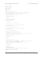
Here is some example C code that will generate the correct serial bytes, given an integer “target” that holds the desired
target (0–4095) and an array called serialBytes:
serialBytes[0] = 0xC0 + (target & 0x1F); // Command byte holds the lower 5 bits of target.
serialBytes[1] = (target >> 5) & 0x7F;
// Data byte holds the upper 7 bits of target.
Many motor control applications do not need 12 bits of target resolution. If you want a simpler and lower-resolution
set of commands for setting the target, you can use the Set Target Low Resolution commands. Alternatively, you
could use the Set Target High Resolution command with the lower 5 bits of the target always zero: sending a 0xC0
byte followed by a data byte (0–127) will result in setting the target to a value of 32 multiplied by the data byte.
Set Target Low Resolution Forward
Compact protocol: 0xE1, magnitude
Pololu protocol: 0xAA, device number, 0x61, magnitude
This command clears the Awaiting Command error bit and (if Input Mode is Serial) sets the target to a value of 2048
or greater which is determined by the magnitude (0–127).
If the Feedback Mode is Analog or Tachometer, then the formula is
Target = 2048 + 16×magnitude.
If the Feedback Mode is None (speed control mode), then the formula is
Target = 2048 + (600/127)×magnitude.
This means that a magnitude of 127 will set the duty cycle target to full-speed forward (+600), while a magnitude of
zero will make the motor stop.
4. Using the Serial Interface
Page 32 of 45
Pololu Jrk USB Motor Controller User's Guide
© 2001–2014 Pololu Corporation
Set Target Low Resolution Reverse
Compact protocol: 0xE0, magnitude
Pololu protocol: 0xAA, device number, 0x60, magnitude
If magnitude is zero, then this command is equivalent to the Motor Off command above: the Awaiting Command
error bit will be set, so the jrk will turn the motor off until another Set Target command is received.
Otherwise, this command clears the Awaiting Command error bit and (if Input Mode is Serial) sets the target to a
value less than 2048 which is determined by the magnitude (0–127).
If the Feedback Mode is Analog or Tachometer, then the formula is
Target = 2048 − 16×magnitude.
If the Feedback Mode is None (speed control mode), then the formula is
Target = 2048 − (600/127)×magnitude.
This means that a magnitude of 127 will set the duty cycle target to full-speed reverse (-600).
4.f. Error Reporting Commands
There are several errors that can stop the jrk from driving its motor. The jrk’s response to the different errors can be
configured (Section 3.f).
Both of the error reporting commands result in a two-byte serial response form the jrk. Each bit in those two bytes
represents a particular error. If the bit is 1, it means that the error occurred or is occurring. If we call the leastsignificant bit 0, and the first byte transmitted contains bits 0-7, then the correspondence between bits of the error
bytes and errors are as follows:
• Bit 0: Awaiting command
If this bit is set, the jrk will not drive the motor until it receives a command that clears this bit. Any version of
the Set Target command will clear the error bit. A Set Target command can be sent from the configuration utility,
from a computer using the virtual Command Port (unless the jrk is configured to receive commands on RX), or
from the RX line if the jrk is configured to receive commands on RX. This error occurs in Serial Input mode
when the Jrk is powered on.
• Bit 1: No power
This error occurs when the jrk is connected to USB, but it detects no motor power connected to VIN and GND,
so it can not drive the motor. If this error occurs, check your power supply and power connections.
• Bit 2: Motor driver error
This error occurs when one of the motor driver’s fault conditions are triggered, and the motor driver shuts down
the motor and reports the error to the jrk’s microcontroller. This error also occurs when the jrk is connected to
USB and motor power becomes disconnected. When this error occurs, the jrk will try to automatically recover
from it by toggling the appropriate lines on the motor driver. The jrk 21v3’s motor driver fault occurs on undervoltage, over-temperature, or over-current conditions. The jrk 12v12’s motor driver fault occurs when it detects
that motor output A is shorted to ground or VIN.
• Bit 3: Input invalid (Pulse Width Input Mode only)
In Pulse Width Input Mode, the jrk will only update the input value if it has received four good pulses in a row.
For example, if the jrk receives five good pulses, a bad pulse, and then five more good pulses, it will update the
input value after pulses 4, 5, 10, and 11. This error occurs if the jrk goes more than 120 ms without updating the
4. Using the Serial Interface
Page 33 of 45
Pololu Jrk USB Motor Controller User's Guide
© 2001–2014 Pololu Corporation
input value. The jrk can recover from the error by receiving four good pulses in a row. This error does not occur
in Analog Input Mode or Serial Input Mode.
• Bit 4: Input disconnect
This error occurs when the input is above the Absolute maximum or below the Absolute minimum (these
parameters can be set in the configuration utility). Additionally, when using the Detect disconnect with AUX
option in Analog Input Mode, the jrk periodically tests to see whether the input potentiometer is disconnected
and generates this error if it finds that it is (Section 3.b).
• Bit 5: Feedback disconnect
This error occurs when the feedback is above the Absolute maximum or below the Absolute minimum (these
parameters can be set in the configuration utility). The absolute maximum and absolute minimum can be set
using the configuration utility. Additionally, when using the Detect disconnect with AUX option in Analog
Feedback Mode, the jrk periodically tests to see whether the feedback potentiometer is disconnected and
generates this error if it finds that it is (Section 3.c).
• Bit 6: Maximum current exceeded
This error occurs when the motor current limit is exceeded. The limit can be set using the configuration utility
(Section 3.e).
• Bit 7: Serial signal error
A hardware-level error that occurs when a byte’s stop bit is not detected at the expected place. This can occur if
you are communicating at a baud rate that differs from the jrk’s baud rate.
• Bit 8: Serial overrun
A hardware-level error that occurs when the UART receive buffer is full. This error should not occur during
normal operation.
• Bit 9: Serial RX buffer full
A firmware-level error that occurs when the firmware’s buffer for bytes received on the RX line is full and a byte
from RX has been lost as a result. This error should not occur during normal operation.
• Bit 10: Serial CRC error
This error occurs when the jrk is running in CRC-enabled mode and the cyclic redundancy check (CRC) byte at
the end of the command packet does not match what the jrk has computed as that packet’s CRC (Section 4.d).
In such a case, the jrk ignores the command packet and generates a CRC error.
• Bit 11: Serial protocol error
This error occurs when the jrk receives an incorrectly formatted or nonsensical command packet. For example,
if the command byte does not match a known command or an unfinished command packet is interrupted by
another command packet, this error occurs.
• Bit 12: Serial timeout error
When the serial timeout is enabled (Section 3.b), this error occurs whenever the timeout period has elapsed
without the jrk receiving any valid serial commands. This timeout error can be used to shut down the motors in
the event that serial communication between the jrk and its controller is disrupted.
• Bits 13-15: Reserved
These bits do not represent any errors; they will always read as zeroes.
Get Error Flags Halting
Compact protocol: 0xB3
Pololu protocol: 0xAA, device number, 0x33
This command generates a two-byte serial response reporting which errors are currently stopping the motor, and
it clears the corresponding error bits (except for the Awaiting Command error bit). This command is useful for
determining why your motor is not turning, and for clearing any latched errors that are enabled. This command will
not report any errors that have been disabled in the configuration utility, because those errors do not stop the motor.
4. Using the Serial Interface
Page 34 of 45
Pololu Jrk USB Motor Controller User's Guide
© 2001–2014 Pololu Corporation
This command is equivalent to reading the “Currently stopping motor?” column in the Errors tab of the configuration
utility, and then clicking the “Clear Errors” button.
If an error is stopping the motor (besides the Awaiting Command error bit), the jrk will turn the red LED on and drive
the ERR line high, and this command can be used to determine the cause of the error.
Get Error Flags Occurred
Compact protocol: 0xB5
Pololu protocol: 0xAA, device number, 0x35
This command generates a two-byte serial response reporting which errors have occurred since the last time the Get
Error Flags Occurred command was received. Unlike the Get Error Flags Halting command, this command has no
effect on the motor.
Note: If the jrk is connected to the configuration utility, then the Get Error Flags Occurred command
will give unreliable responses, because the configuration utility runs this command regularly. This
command will report all the errors that have occurred since the last time the Get Error Flags Occurred
command was received, regardless of whether that last command came from the configuration utility,
from your microcontroller, or from the jrk’s virtual Command Port.
4.g. Variable Reading Commands
Compact protocol: read variable command byte
Pololu protocol: 0xAA, device number, read variable command byte with MSB clear
The jrk has several serial commands for reading its variables. Most of the variables are two bytes long. For each of
those variables, three variable reading commands are provided:
• Two bytes: These commands will result in a two-byte serial response from the jrk containing both bytes of
the variable. All variables are little endian, so the first byte transmitted will be the least-significant byte, and the
second byte transmitted will be the most-significant byte. For variables that can have negative values, the two’s
complement system is used (a response of 0xFE, 0xFF means -2).
• Low byte: These commands will result in a one-byte serial response from the jrk containing just the leastsignificant byte of the variable.
• High byte: These commands will result in a one-byte serial response from the jrk containing just the mostsignificant byte of the variable.
The command bytes are listed in the table below.
4. Using the Serial Interface
Page 35 of 45
Pololu Jrk USB Motor Controller User's Guide
© 2001–2014 Pololu Corporation
Read Variable Command Byte
Variable
Range
Two bytes Low byte High byte
Input
0 to 4095
0xA1
0x81
0x82
Target
0 to 4095
0xA3
0x83
0x84
Feedback
0 to 4095
0xA5
0x85
0x86
Scaled feedback
0 to 4095
0xA7
0x87
0x88
Error sum (integral) -32,768 to 32,767 0xA9
0x89
0x8A
Duty cycle target
-32,768 to 32,767 0xAB
0x8B
0x8C
Duty cycle
-600 to 600
0x8D
0x8E
Current
0 to 255
PID period count
0 to 65535
0xAD
0x8F
0xB1
0x91
0x92
The meaning of the variables is described below:
• Input: The input is the raw, un-scaled input value, representing a measurement taken by the jrk of the input
to the system. In serial input mode, the input is equal to the target, which can be set to any value 0–4095 using
serial commands. In analog input mode, the input is a measurement of the voltage on the RX pin, where 0 is 0 V
and 4092 is 5 V. In pulse width input mode, the input is the duration of the last pulse measured, in units of 2/3 μs.
See Section 3.b for more information.
• Target: In serial input mode, the target is set directly with serial commands. In the other input modes, the
target is computed by scaling the input. The scaling can be configured in the “Scaling” box of the Input tab in
the configuration utility.
• Feedback: The feedback is the raw, un-scaled feedback value, representing a measurement taken by the jrk
of the output of the system. In analog feedback mode, the feedback is a measurement of the voltage on the FB
pin, where 0 is 0 V and 4092 is 5 V. In no feedback mode (speed control mode), the feedback is always zero.
• Scaled feedback: The scaled value of feedback. The feedback scaling can be configured in the “Scaling” box
of the Feedback tab in the configuration utility.
• Current: The value of this variable is proportional to the current running through the motor: on the jrk 21v3,
a value of 1 nominally represents 38 mA of current in the motor, while on the jrk 12v12 a value of 1 nominally
represents 149 mA of current in the motor . However, the circuitry on the motor driver chips varies between
different units, and they can vary depending on which direction the motor is driving, so these calibration values
will not always be right for every jrk. The value of this variable will always be zero unless a current limit is
enabled. See Section 3.e for more information about current measurement and calibration.
• Error sum (integral): Every PID period, the error (scaled feedback minus target) is added to the error sum.
The error sum gets reset to zero whenever the jrk is not driving the motor, and can optionally be reset whenever
the proportional term of the PID calculation exceeds the maximum duty cycle. There is also a configurable
integral limit that the integral can not exceed.
• Duty cycle target: Represents the duty cycle that the jrk is trying to achieve. A value of -600 or less means
full speed reverse, while a value of 600 or more means full speed forward. A value of 0 means braking. In no
feedback mode (speed control mode), the duty cycle target is the target minus 2048. In other feedback modes,
the duty cycle target is the sum of the proportional, integral, and derivative terms of the PID algorithm.
• Duty cycle: Represents the duty cycle that the jrk is driving the motor with. A value of -600 or less means full
speed reverse, while a value of 600 or more means full speed forward. A value of 0 means braking. The absolute
value of the duty cycle will always be less than the absolute value of the duty cycle target. The duty cycle is
4. Using the Serial Interface
Page 36 of 45
Pololu Jrk USB Motor Controller User's Guide
© 2001–2014 Pololu Corporation
different from the duty cycle target because it takes in to account all of the jrk’s configurable limits: maximum
acceleration, maximum duty cycle, maximum current, and also brake duration (Section 3.e).
• PID period count: This is the number of PID periods that have elapsed. It resets to 0 after reaching 65535.
The duration of the PID period can be configured (Section 3.d).
Note: All command bytes from 0x81 to 0xBF that are not listed in this section or Section 4.f are
undocumented variable reading commands that will result in a serial response from the jrk and not
generate a serial protocol error. These commands are not useful, but they are not harmful.
4.h. Daisy-Chaining
This section is a guide to integrating the jrk in to a project that has multiple TTL serial devices that use the Pololu
Protocol or some compatible protocol. This section contains no new information about the jrk: all of the information
in this section can be deduced from the definitions of the three serial modes (Section 4.a) and the Pololu Protocol
(Section 4.c).
First of all, assign each device in the project a different device number so that they can be individually addressed
by Pololu Protocol serial commands. For the jrk, this can be done in the Input tab of the configuration utility.
The following diagram shows how to connect one master and many slave devices together into a chain. Each
of the devices may be a jrk or any other device compatible with the Pololu Protocol, such as a qik
[http://www.pololu.com/product/1110],
servo controller [http://www.pololu.com/category/12/rc-servo-controllers], or a
microcontroller.
Daisy chaining serial devices using the Pololu
protocol. An optional AND gate is used to join
multiple TX lines.
Using a PC and a jrk together as the master device
The jrk can enable a personal computer to be the master device. The jrk must be connected to a PC with a USB cable
and configured to be in either USB Dual Port or USB Chained serial mode. Serial input mode must be used to
receive responses from slave devices (if you do not need to receive reponses, you may use other input modes). In USB
Dual Port mode, the Command Port on the PC is used for sending commands directly to the jrk, and the TTL Port on
the PC is used to send commands to all of the slave devices. In the USB Chained mode, only the Command Port is
used on the PC, to communicate with the jrk and all of the slave devices. Select the mode that is most convenient for
your application or easiest to implement in your programming language.
Using a jrk as a slave device
The jrk can act as a slave device when configured to be in the UART serial mode and Serial input mode. In this
mode, commands are received on the RX line, and responses are sent on the TX line. A USB connection to a PC is
not required, though an RX-only Comand Port is available on the PC for debugging or other purposes.
4. Using the Serial Interface
Page 37 of 45
Pololu Jrk USB Motor Controller User's Guide
© 2001–2014 Pololu Corporation
Connections
Connect the TX line of the master device to the RX lines of all of the slave devices. Commands sent by the master
will then be received by all slaves.
Receiving serial responses from one the slave devices on the PC can be achieved by connecting the TX line of that
slave device to the RX line of the jrk.
Receiving serial responses from multiple slave devices is more complicated. Each device should only transmit when
requested, so if each device is addressed separately, multiple devices will not transmit simultaneously. However, the
TX outputs are driven high when not sending data, so they cannot simply be wired together. Instead, you can use
an AND gate, as shown in the diagram, to combine the signals. Note that in many cases receiving responses is not
necessary, and the TX lines can be left unconnected.
If there are multiple slave jrks, you can connect all of the jrks’ ERR lines to a single input on a microcontroller to
monitor the error state.
Whenever connecting devices, remember to wire the grounds together, and ensure that each device
is properly powered. Unpowered devices with a TTL serial port can turn on or partially on, drawing
power from the serial line, which means that extra care must be taken when turning power off and on
to reset the devices.
Sending commands
The Pololu Protocol should be used when multiple Pololu devices are receiving the same serial data. This allows the
devices to be individually addressed, and it allows responses to be sent without collisions.
If the devices are configured to detect the baud rate, then when you issue your first Pololu Protocol command, the
devices can automatically detect the baud from the initial 0xAA byte.
Some older Pololu devices use 0x80 as an initial command byte. If you want to chain these together with devices
expecting 0xAA, you should first transmit the byte 0x80 so that these devices can automatically detect the baud rate,
and only then should you send the byte 0xAA so that the jrk can detect the baud rate. Once all devices have detected
the baud rate, Pololu devices that expect a leading command byte of 0x80 will ignore command packets that start with
0xAA, and jrks will ignore command packets that start with 0x80.
4.i. Serial Example Code
4.i.1. Cross-platform C
The example C code below works on Windows, Linux, and Mac OS X 10.7 or later. It demonstrates how to set the
target of a jrk by sending a Set Target command to its Command Port, and how to read variables from the jrk. The
jrk’s input mode must be set to “Serial” and the serial mode must be “USB Dual Port” for this code to work. You will
also need to modify the line that specifies the name of the COM port device.
This code will work in Windows if compiled with MinGW, but it does not work with the Microsoft C
compiler. For Windows-specific example code that works with either compiler, see Section 4.i.2.
//
//
//
//
Uses POSIX functions to send and receive data from a jrk.
NOTE: The jrk's input mode must be "Serial".
NOTE: The jrk's serial mode must be set to "USB Dual Port".
NOTE: You must change the 'const char * device' line below.
4. Using the Serial Interface
Page 38 of 45
Pololu Jrk USB Motor Controller User's Guide
© 2001–2014 Pololu Corporation
#include <fcntl.h>
#include <stdio.h>
#include <unistd.h>
#ifdef _WIN32
#define O_NOCTTY 0
#else
#include <termios.h>
#endif
// Reads a variable from the jrk.
// The 'command' argument must be one of the two-byte variable-reading
// commands documented in the "Variable Reading Commands" section of
// the jrk user's guide.
int jrkGetVariable(int fd, unsigned char command)
{
if(write(fd, &command, 1) == -1)
{
perror("error writing");
return -1;
}
unsigned char response[2];
if(read(fd,response,2) != 2)
{
perror("error reading");
return -1;
}
}
return response[0] + 256*response[1];
// Gets the value of the jrk's Feedback variable (0-4095).
int jrkGetFeedback(int fd)
{
return jrkGetVariable(fd, 0xA5);
}
// Gets the value of the jrk's Target variable (0-4095).
int jrkGetTarget(int fd)
{
return jrkGetVariable(fd, 0xA3);
}
// Sets the jrk's Target variable (0-4095).
int jrkSetTarget(int fd, unsigned short target)
{
unsigned char command[] = {0xC0 + (target & 0x1F), (target >> 5) & 0x7F};
if (write(fd, command, sizeof(command)) == -1)
{
perror("error writing");
return -1;
}
return 0;
}
int main()
{
// Open the Jrk's virtual COM port.
const char * device = "\\\\.\\USBSER000"; // Windows, "\\\\.\\COM6" also works
//const char * device = "/dev/ttyACM0"; // Linux
//const char * device = "/dev/cu.usbmodem00000041"; // Mac OS X
int fd = open(device, O_RDWR | O_NOCTTY);
if (fd == -1)
{
perror(device);
return 1;
}
#ifndef _WIN32
struct termios options;
tcgetattr(fd, &options);
options.c_lflag &= ~(ECHO | ECHONL | ICANON | ISIG | IEXTEN);
options.c_oflag &= ~(ONLCR | OCRNL);
tcsetattr(fd, TCSANOW, &options);
#endif
4. Using the Serial Interface
Page 39 of 45
Pololu Jrk USB Motor Controller User's Guide
© 2001–2014 Pololu Corporation
int feedback = jrkGetFeedback(fd);
printf("Current Feedback is %d.\n", feedback);
int target = jrkGetTarget(fd);
printf("Current Target is %d.\n", target);
int newTarget = (target < 2048) ? 3000 : 1000;
printf("Setting Target to %d.\n", newTarget);
jrkSetTarget(fd, newTarget);
}
close(fd);
return 0;
4.i.2. Windows C
For example C code that shows how to control the jrk using its serial interface in Microsoft Windows, download
JrkSerialCWindows.zip [http://www.pololu.com/file/download/JrkSerialCWindows.zip?file_id=0J556] (4k zip). This zip
archive contains a Microsoft Visual C++ 2010 Express project that shows how to send a Set Target command and
also a Get Position command. It can also be compiled with MinGW. The jrk’s input mode needs to be set to “Serial”
and the serial mode needs to be set to “USB Dual Port” for this code to work. This example is like the previous
example except it does the serial communication using Windows-specific functions like CreateFile and WriteFile. See
the comments in the source code for more details.
4. Using the Serial Interface
Page 40 of 45
Pololu Jrk USB Motor Controller User's Guide
© 2001–2014 Pololu Corporation
5. Setting Up Your System
The following step-by-step procedure is recommended for configuring a feedback system for use with a jrk motor
controller.
Connecting power and feedback
1. Connect your jrk to a PC with a USB cable and launch the configuration utility. The red LED should be on.
2. Select the “Reset to default settings…” option from the File menu to load a safe set of settings.
3. With your power supply off, make the power connections to VIN and GND.
4. Connect your feedback sensor to the FB input. If you are using a potentiometer as a feedback sensor, use the
AUX pin to power it, and enable Detect disconnect with AUX in the Feedback tab.
5. Set the “No power”, “Motor driver error”, “Feedback disconnect”, and “Max. current exceeded” errors on
the Error tab to Enabled and latched. This should stop your system in case of any major problem.
6. Click “Apply settings to device”.
7. Turn on power.
8. On the Error tab, click “Clear Errors” to remove the errors caused by turning off the power.
The red LED should now be off, and the yellow LED should be blinking slowly, indicating that the board has power
but that no target has been set. If the red LED is on, examine the Errors tab to determine the source of the problem.
Look at the value of Scaled Feedback displayed at the top of the window, and verify that it changes if you manually
adjust the feedback sensor.
Calibrating feedback
1. Select the correct value for Feedback mode.
2. Click “Learn…” on the Feedback tab. You will be prompted to turn the output to its minimum and maximum
positions, so that readings of the feedback sensor can be determined at each extreme.
3. Examine the resulting values and adjust if desired. Your system will be safer if you set Absolute Max. and
Absolute Min. to values that the system can actually reach, so that if motion takes it past those extremes, the jrk
will automatically shut down (because of the “Feedback disconnect” error.)
4. Click “Apply settings to device”.
5. Move the system to the middle of its range.
Setting motor limits
1. Set Max. duty cycle to a safe value, like 200.
2. Set Max. current to a safe value, like 500 mA. You want values that will turn the motor but not give it enough
power to do any damage if something goes wrong.
3. Set other limits as necessary.
4. Click “Apply settings to device”.
Connecting the motor
From this point on, be prepared to shut down the system by clicking “Stop motor” or turning off your
power supply if anything goes wrong and the limits and errors set previously fail to stop the motor.
5. Setting Up Your System
Page 41 of 45
Pololu Jrk USB Motor Controller User's Guide
© 2001–2014 Pololu Corporation
1. Turn off power.
2. Connect your motor wires to the jrk’s A and B motor outputs. If possible, connect them so that positive
voltage at A causes the motor to drive forward.
3. Turn on power.
Testing the motor
1. If possible, drive your motor with feedback disabled. To do this, make sure that the Feedback mode is set to
none and use the controls on the Input tab to apply different duty cycles. Of course, this requires you to have a
system that does not destroy itself when run without feedback.
2. On the Error tab, click “Clear Errors” to remove the errors caused by turning off the power.
3. On the Motor tab, click the “Detect Motor Direction” button. This will apply some power to the motor and
measure the direction that feedback moves in response. If the motor is connected “reversed” with respect to your
feedback sensor, then Invert motor direction will be checked.
4. Click “Apply settings to device” to apply any changes.
Testing basic feedback
1. In the PID tab, choose a Proportional Coefficient of 1 and leave the other two constants at zero. This will
probably drive your motor at its maximum duty cycle, so make sure that this and other motor parameters are
configured correctly.
2. Click “Apply settings to device”.
3. Use the slider on the Input tab to send various input values to your jrk, and see how it behaves.
If you did everything correctly, your feedback system should now be active, approximately following the target value.
Tuning the PID constants
Tuning PID constants is a complicated process that can be approached in many different ways. Here we will give a
basic procedure that works for some systems, but you will probably want to try various different methods for finding
the best possible values. You will want to have the Plots window open, displaying a nice view of the Error, Target,
Scaled Feedback, and Duty Cycle. When setting the Integral Coefficient, it will also be useful to look at the value of
the Integral.
1. Increase your Max. duty cycle, Max. current, and other limits to reasonable values for high-performance
operation of your system.
2. Try increasing the Proportional Coefficient until you reach a point where the system becomes unstable. Note
that the stability could be different at different target positions, so try the full range of motion when hunting for
instability.
3. Decrease the value from the point of instability by about 40-50%. This is the first step of the Ziegler-Nichols
Method [http://en.wikipedia.org/wiki/Ziegler%E2%80%93Nichols_method].
5. Setting Up Your System
Page 42 of 45
Pololu Jrk USB Motor Controller User's Guide
© 2001–2014 Pololu Corporation
4. Note how close your system gets to an error of zero using just the
proportional term. You can use the integral term to get it much lower:
with the integral limit set at 1000, try increasing the Integral Coefficient
until you see a correction that brings the error closer to zero. In the plot
window shown here, you can see that the proportional term gets the error
down to about 10, then the integral term builds up and, half a second
later, moves the motor just a bit, reducing the error to ±1.
5. For systems that have a lot of friction relative to external forces,
enable a Feedback dead zone so that the integral term doesn’t cause a
slow oscillation very close to an error of zero. Watch how the integral
term and duty cycle build up over time to achieve. this. The plot was created with a dead zone of 4; without this,
the integral term would have continued to build up, but at a slower rate, after the first adjustment.
6. Enable the Reset integral when proportional term exceeds max duty cycle option to prevent the integral from
winding up during large motions. This is also shown in the plot: the integral term does not start increasing until
the error is close to zero.
7. Have your system take large steps (for example, by clicking the bar
area of the Input tab scrollbar to move the target by 200) and use the
graph to examine whether it consistently overshoots (crosses zero before
coming to a stop and moving back) or undershoots (does not reach zero
before slowing down). The plot window shown here, drawn for a system
using a Derivative Coefficient of zero, shows clear overshooting. In this
example, the error actually oscillates back and forth several times before
settling down.
8. Increase the Derivative Coefficient to get rid of any overshooting,
but not so much that it undershoots. The plot window shown here
demonstrates undershooting, using a Derivative Coefficient of 10. You
can see that the error never reaches zero. Instead, it gradually approaches
zero after each step.
9. Experiment with your system. Adjust any parameters as necessary to
get the behavior that you need.
The following example plot shows a well-tuned system, with Proportional,
Integral, and Derivative Coefficients of 6.0, 0.25, and 7.5. When taking
steps, the system stops very quickly at a position with very small error, randomly overshooting or undershooting by a
small amount.
5. Setting Up Your System
Page 43 of 45
Pololu Jrk USB Motor Controller User's Guide
5. Setting Up Your System
© 2001–2014 Pololu Corporation
Page 44 of 45
Pololu Jrk USB Motor Controller User's Guide
© 2001–2014 Pololu Corporation
6. Writing PC Software to Control the Jrk
There are two ways to write PC software to control the jrk: the native USB interface and the virtual serial port.
The native USB interface provides more features than the serial port, such as the ability to change configuration
parameters and select the jrk by its serial number. Also, the USB interface allows you to recover more easily from
temporary disconnections. The virtual serial port interface is easier to use if you are not familiar with programming,
and it can work with existing software programs that use serial ports, such as LabView.
Native USB Interface
The Pololu USB Software Development Kit
includes C# source code for:
[http://www.pololu.com/docs/0J41]
supports Windows and Linux, and
• JrkExample: an example graphical application that uses native USB to send commands and receive feedback
from the jrk and automatically recover from disconnection.
• JrkCmd: a command-line utility for configuring and controlling the jrk. JrkCmd has a streaming mode that
allows you to steadily stream all of the jrk variables to the computer and output them in comma-separated format
in case you want to make your own graphs or do something special with the data.
• C# .NET class libraries that enable native USB communication with the jrk.
You can modify the applications in the SDK to suit your needs or you can use the class libraries to integrate the
jrk in to your own applications. Advanced users can also use the source code as a reference when writing custom
applications in any language that control the jrk over USB.
Virtual Serial Ports
Almost any programming language is capable of accessing the COM ports created by the jrk. We recommend the
Microsoft .NET framework, which is free to use and contains a SerialPort class that makes it easy to read and write
bytes from a serial port. You can download Visual Studio Express (for either C#, C++, or Visual Basic) and write
programs that use the SerialPort class to communicate with the jrk. You will need to set the jrk’s serial mode to be
either “USB Dual Port” or “USB Chained”.
6. Writing PC Software to Control the Jrk
Page 45 of 45