1
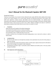
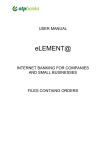
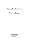
Technique S pecification
DR
Product Size
Anycontrol basic technique specification list:
R
RINGDER
RINGDER
PID Temperature
Controller for Heating
RC-113M
Power supply
Rated power
Load capacity
Sensor type
220VAC±15%/50HZ
≤1. 5W
After connecting the wire, install the waterproof tailgate
(3rd step,Figure2. c);
IP65
Work or storage
Temp. range
Environment
Wire length
-10~60℃,RH<90% no condensation
-10~100℃
Comply with environmental standards
Communication: 1Km,sensor:100m
Function and Parameter
Function
Code
F01 Set Low Limit
F02 Set High Limit
F03 Calibration
Setting Range
-10~Set temp.
Set temp.~100
-7~7
Default
-10
100
0.0
Wiring Diagram
Unit
Figure2 . c
2A/250V
220V/50HZ
How to disassemble the controller from the hole?
WEB: WWW.RINGDER.NET
Load
Product Introduction
This model is specially designed for elaborate heating
system, which adopt high accuracy temperature sensor,
PID control, minimum temperature inertia, very high
control accuracy(0.1C within normal temperature
period).
1.1 Temperature measurement
1.1.1 Temperature calibration
1.1.2 Sampling period
various equipments and places that need to control
The sampling period of this model is 1 second fixedly, and other
sampling period can be customized.
temperature accurately, such as incubator, Heating
1.2 Temperature control
equipment in the laboratory etc.
Temperature controlling parameters: ST, F01,F02.
ST: is stop temperature that can be adjusted by SET key directly.
F01: is the low limit of setting temp.
F02: is the high limit of setting temp.
These two parameters is used to limit the setting temp range in
order to avoid misoperation.
Xuzhou Ringder Electrical Equipment Co., Ltd.
E-mail:[email protected]
Tel: 86-516-66656756 /87764448 FAX: 86-516-87769006
Website: http://www.ringder.net/indexen.asp;
http://ringder.en.alibaba.com/
Address: No. 385, Zhongshan North Road,Gulou District,Xuzhou City,Jiangsu Province, China.
Power
Sensor
F01≤ST≤F02
1.2.1Heating status description
The controller can PID adjust the power of the heater, and make
the temperature constant around the setting temp. During
25~42℃, the accuracy can be 0.1℃.
Firstly disassemble the
tailgate, then press the
position(Figure2.d)
sliding backwards to
disassemble the controler;
Figure2 . d
Connect the wires strictly according to the diagram, the voltage
User Interface & Button Function
must within 220VAC±10%.
The current of the load must: inductive load or filament lamp≤
10% of the current on the wiring diagram; resistive load≤60% of
When there is some difference between the measuring
temperature and the real temperature, the difference can be
calibrated by menu F3, and calibration method should follow
the below formula:F3=real temperature-measuring
temperature. Other functions will execute according to the
calibrated temperature value.
RC-113M PID temperature controller is widely applied to
Top Runner in Temperature Measuring and Controlling Industry
Figure2.b
NTC, 25℃/ 50KΩ
Protection class
User Manual
Figure2 . a
MAX resistive load:440W/220V/50HZ
3.1 Display Area
the current on the wiring diagram.
1
Assembly and Installation
2
2.1 Assembly
Warning:
3
Please
refer to
The controller must be connected by trained electricians
according to the user manual strictly, and avoid installing in the
below environments:
Relative humidity> 90 % ,have condensation
The places that temperature<-10℃ or>60℃;
The places that have inflammables and explosives;
Strong vibration or struck
Exposed to the continuous water mist spraying;
Exposed to the dust;
Exposure to corrosive and pollution gas (for example:the gas,
smoke or salt fog that contain sulfur or ammonia;
Wireless electromagnetic interference or strong magnetic
fields(near to transmitting antenna or switch board room);
2.2 Please install the controller according to the following
Cut out a hole at the installing postion:7 1* 2 9mm
Detach the slide fasteners, and put the controller into the hole.
(1st step,Figure2.a);
Install the faterners;
(2nd step,Figure2.b);
No.
Meaning
Alarm
Heat Equipment
Set Indicator
Working Status
Display
/
Work status
Set status
Not Display
Non alarm status
Stop status
Non set status
Flash
Alarm status
/
/
Alarm, Error & Toubleshooting
3.2 Set the stop temperature
Press SET key can set the stop temperature,press
key can adjust the stop temperature; when finishing
adjustment,
press RST key to save and exit, or auto save and exit after 15
seconds without any operation.
Normal working status
Alarm error and troubleshooting
When alarm occur,
icon flash, and buzzer sounds, if it is not
sensor fault, the fault code and temperature value will alternate
display, e.g. If it show FS, means the room sensor temp exceed
the storage protection temp in the defrost mode; if it is sensor
fault, it will only display the fault code.
Adjust
Single-press
Code
SET
RST
Single-press or
no operation 15 sec.
Reason
Troubleshooting
Sensor short circuit Check the temperature of environment
EEH
Normal working status
or exceed the
where the sensor is placed, and whether
highest measuring the sensor is short circuit, then repair
temperature
correspondingly.
Sensor open circuit Check the temperature of environment
EEL
or exceed the
where the sensor is placed, and whether
lowest measuring
the sensor is open circuit, then repair
temperature
correspondingly.
3.2 Set Other Parameters
Press SET key for 3 seconds, enter into menu setting mode.
Press
,
key can shift parameter. If need to change
the value of the parameter, press SET key, then use
key
to adjust the parameters’s value. When finishing setting, press
SET key to return to menu.Adjust the parameters in turn. When
finishing all settings, press RST key 3 seconds or no
operation for 15 seconds to save and exit.
Normal working status
Show low temp limit
Shift menu
Press on
3 sec.
SET
SET
Attention:
When alarming, press any key to mute the alarm, but the icon
will keep flashing, and the fault code will keep displaying until
trouble removal.
Accessory
Sensor wire x 1; slide fastener x 2
tailgate x 1; user manual x 1;
Single-press
4.1 Sensor
The sensors that meet RINGDER criteria can apply to the
product, and the sensor cannot be put into the water directly.
Set low temp limit
Adjust
Show high temp limit
Shift menu
The below is some parameters:
Wire: φ2.1mm*2m ; sensor size: φ4mm*20mm
SET
SET
Single-press
Single-press
Attention please:
Please avoid overload, load short circuit, misuse, human
damage etc., which is not covered by the warranty. Load
short circuit can damage the PID output immediately!
Set high temp limit
Adjust
Calibration
The controller can be installed as far as about 100m,
but the cross section of the shielded wire must above 1mm
and any head of the wire mustn’t connect earth.
SET
SET
Single-press
Set calibration
Shift menu
Adjust
Normal working status
Single-press or
no operation 15 sec.
RST
Single-press
This model controller adopts NTC sensor without positive
and negative polarity, so no requirement for connection
order.
Please choose the suitable wire rod to connect, and check
connection fastness.
Please remember to cut off the power supply before
connecting.
This product has passed the European CE certification,
and conform to ISO9001 total quality control system.