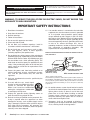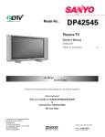
1
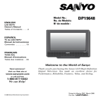
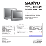
Model No:
No. de Modelo:
DP42746
HIGH-DEFINITION TELEVISION
Plasma TV
Owner’s Manual
ENGLISH
Table of Contents . . . . . 3
TV de Plasma
Manual de Instrucciónes
ESPAÑOL
Contenido . . . . . . . . . . 29
As Real As It Gets!
“Read this manual before assembling (or using) this product.”
™
Need assistance?
Visit our website at
www.sanyoctv.com
or
Call toll free 1.800.877.5032
®
We can Help!
ENERGY STAR
“As an ENERGY STAR® Partner, Sanyo
Manufacturing Corporation has determined
that this product meets the ENERGY STAR®
guidelines for energy efficiency.”
© 2006 Sanyo Manufacturing Corporation
Importado Por : Comercializadora México
Americana, S. DE R.L. DE C.V.
Nextengo No 78
Col. Santa Cruz Acayucan
Del. Azcapotzalco, México D.F. C.P. 02770
RFC CMA 9109119L0
Telefono: 55-5328-3500
Printed in U.S.A. SMC, March 2006
Impreso en U.S.A. SMC, Marzo 2006
Part No. / No. de Parte : 1AA6P1P5111– –
CAUTION
RISK OF ELECTRIC SHOCK DO NOT OPEN
CAUTION: TO REDUCE THE RISK OF ELECTRIC SHOCK, DO NOT REMOVE COVER (OR
BACK). NO USER-SERVICEABLE PARTS INSIDE. REFER SERVICING TO QUALIFIED
SERVICE PERSONNEL.
THIS SYMBOL INDICATES THAT DANGEROUS VOLTAGE CONSTITUTING A RISK OF ELECTRIC SHOCK IS PRESENT WITHIN THIS UNIT.
THIS SYMBOL INDICATES THAT THERE ARE IMPORTANT OPERATING
AND MAINTENANCE INSTRUCTIONS IN THE LITERATURE ACCOMPANYING THIS UNIT.
WARNING: TO REDUCE THE RISK OF FIRE OR ELECTRIC SHOCK, DO NOT EXPOSE THIS
APPLIANCE TO RAIN OR MOISTURE.
IMPORTANT SAFETY INSTRUCTIONS
1. Read these instructions.
2. Keep these instructions.
3. Heed all warnings.
4. Follow all instructions.
5. Do not use this apparatus near water.
6. Clean only with dry cloth.
7. Do not block any ventilation openings. Install in
accordance with the manufacturer’s instructions.
8. Do not install near any heat sources such as radiators, heat registers, stoves, or other apparatus
(including amplifiers) that produce heat.
9. Do not defeat the safety purpose of the polarized or
grounding-type plug. A polarized plug has two blades
with one wider than the other. A grounding-type plug
has two blades and a third grounding prong. The
wide blade or the third prong are provided for your
safety. If the provided plug does not fit fully into your
outlet, consult an electrician for replacement of the
obsolete outlet.
10. Protect the power cord from being walked on or
pinched particularly at plugs, convenience receptacles, and the point where they exit from the
apparatus.
11. Only use attachments/accessories specified by the
manufacturer.
12. Use only with the cart, stand, tripod,
bracket, or table specified by the manufacturer, or sold with the apparatus.
When a cart is used, use caution when
moving the cart/apparatus combination
to avoid injury from tip-over.
13. Unplug this apparatus during lightning storms or
when unused for long periods of time.
14. Refer all servicing to qualified service personnel. Servicing is required when the apparatus has been
damaged in any way, such as power-supply cord or
plug is damaged, liquid has been spilled or objects
have fallen into the apparatus, the apparatus has
been exposed to rain or moisture, does not operate
normally, or has been dropped.
2
15. If an outside antenna is connected to the television
equipment, be sure the antenna system is grounded
so as to provide some protection against voltage
surges and built up static charges. In the U.S. Selection 810-21 of the National Electrical Code provides
information with respect to proper grounding of the
mast and supporting structure, grounding of the leadin wire to an antenna discharge unit, size of
grounding conductors, location of antenna discharge
unit, connection to grounding electrodes, and
requirements for the grounding electrodes.
EXAMPLE OF ANTENNA GROUNDING ACCORDING TO NATIONAL ELECTRICAL
CODE, ANSI/NFPA 70
ANTENNA
LEAD IN
WIRE
GROUND
CLAMP
ELECTRIC
SERVICE
EQUIPMENT
GROUND CLAMPS
POWER SERVICE GROUNDING
ELECTRODE SYSTEM
(NEC ART 250, PART H)
ANTENNA
DISCHARGE UNIT
(NEC SECTION 810-20)
GROUNDING CONDUCTORS
(NEC SECTION 810-21)
NEC - NATIONAL ELECTRICAL CODE
“Note to CATV system installer:
This reminder is provided to call the CATV system installer’s attention to
Article 820-40 of the NEC that provides guidelines for proper grounding
and, in particular, specifies that the cable ground shall be connected to
the grounding system of the building, as close to the point of cable entry
as practical.”
16. An outside antenna system should not be located in
the vicinity of overhead power lines or other electrical
light or power circuits, or where it can fall into such
power lines or circuits. When installing an outside
antenna system, extreme care should be taken to
keep from touching such power lines or circuits as
contact with them might be fatal.
17. "Apparatus shall not be exposed to dripping or
splashing and no objects filled with liquids, such as
vases, shall be placed on the apparatus."
Need help? Visit our Web site at www.sanyoctv.com or Call 1-800-877-5032
TO THE OWNER
Welcome to the World of Sanyo
Thank you for purchasing this Sanyo Plasma High-Definition
television. You made an excellent choice for Performance,
Reliability, Features, Value, and Styling.
Important Information
Before installing and operating this Plasma DTV, read this
manual thoroughly. This Plasma DTV provides many convenient
features and functions. Operating the Plasma DTV properly
enables you to manage those features and maintain it in good
condition for many years to come. Improper operation may
result in not only shortening the product-life, but may also
cause malfunctions or other serious problems.
If your Plasma DTV seems to operate improperly, read this
manual again, check operations and cable connections and try
the solutions in the “Helpful Hints” section, page 26 of this
manual. If the problem still persists, visit our website at
www.sanyoctv.com or call 1.800.877.5032. We Can Help!
CONTENTS
Important Safety Instructions . . . . . . . . . . . . . . . . . . . . . . . 2
To The Owner . . . . . . . . . . . . . . . . . . . . . . . . . . . . . . . . . . 3
Contents . . . . . . . . . . . . . . . . . . . . . . . . . . . . . . . . . . . . . . 3
Features . . . . . . . . . . . . . . . . . . . . . . . . . . . . . . . . . . . . . . 4
Specifications . . . . . . . . . . . . . . . . . . . . . . . . . . . . . . . . . . 4
Handling Precautions . . . . . . . . . . . . . . . . . . . . . . . . . . . . . 5
Care and Cleaning . . . . . . . . . . . . . . . . . . . . . . . . . . . . . . . 5
Cleaning the Plasma DTV . . . . . . . . . . . . . . . . . . . . . . . . . . . . . . . . 5
Caring for the Plasma DTV . . . . . . . . . . . . . . . . . . . . . . . . . . . . . . . 5
Installation Precautions . . . . . . . . . . . . . . . . . . . . . . . . . . . 6
Child Safety . . . . . . . . . . . . . . . . . . . . . . . . . . . . . . . . . . . . . . . . . . 6
Typical Home Theater Connections . . . . . . . . . . . . . . . . . . 15
Using the Remote Control . . . . . . . . . . . . . . . . . . . . . . . . . 16
Precautions . . . . . . . . . . . . . . . . . . . . . . . . . . . . . . . . . . . . . . . . . . 16
Remote Control Keys . . . . . . . . . . . . . . . . . . . . . . . . . . . . . . 16 ~ 17
TV Adjustment and Setup . . . . . . . . . . . . . . . . . . . . . . . . . 18
Basic Menu Operation . . . . . . . . . . . . . . . . . . . . . . . . . . . . . . . . . . 18
Menu Navigation Map . . . . . . . . . . . . . . . . . . . . . . . . . . . . . . . . . . 18
Menu Options:
All Channel Search . . . . . . . . . . . . . . . . . . . . . . . . . . . . . . . . . . . . . 18
Digital Cable Search (Optional) . . . . . . . . . . . . . . . . . . . . . . . . . . . 19
Positioning Precautions . . . . . . . . . . . . . . . . . . . . . . . . . . . . . . . . . 6
Digital Add-on Search . . . . . . . . . . . . . . . . . . . . . . . . . . . . . . . . . . 19
Removing the Plasma Stand (Feet) (Optional) . . . . . . . . . . . . . . . . 6
Analog Antenna Signal Selection (Optional) . . . . . . . . . . . . . . . . . 20
First-Things-First (Required Initial Setup) . . . . . . . . . . . . . . . 7
Channel Scan Memory . . . . . . . . . . . . . . . . . . . . . . . . . . . . . . . . . 20
Initial Signal Connections . . . . . . . . . . . . . . . . . . . . . . . . . . . . . . . . 7
Digital Caption . . . . . . . . . . . . . . . . . . . . . . . . . . . . . . . . . . . . . . . . 21
Digital RF Antenna Connection . . . . . . . . . . . . . . . . . . . . . . . . . . . 7
Changing the Look of Digital Captions . . . . . . . . . . . . . . . . . . . 21
Analog RF Antenna Connection . . . . . . . . . . . . . . . . . . . . . . . . . . 7
To View Captions . . . . . . . . . . . . . . . . . . . . . . . . . . . . . . . . . . . . 21
Install Batteries . . . . . . . . . . . . . . . . . . . . . . . . . . . . . . . . . . . . . . . . 8
V-Guide (Parental Control) . . . . . . . . . . . . . . . . . . . . . . . . . . . . . . 22
Connect AC Power Cord . . . . . . . . . . . . . . . . . . . . . . . . . . . . . . . . . 8
To Block MPAA Movie or TV Program . . . . . . . . . . . . . . . . . . . . 22
All Channel Search . . . . . . . . . . . . . . . . . . . . . . . . . . . . . . . . . . . . . . 8
To Setup V-Guide Ratings . . . . . . . . . . . . . . . . . . . . . . . . . . . . . 22
Analog Antenna Signal Selection (Optional) . . . . . . . . . . . . . . . . . . 8
Top and Back Panels . . . . . . . . . . . . . . . . . . . . . . . . . . . . . 9
Choose Your Connection . . . . . . . . . . . . . . . . . . . . . . . . . . 10
Digital AV Connections
Connecting External Equipment to HDMI Input . . . . . . . . . . . . . . . 11
Connect STB or DVD with DVI Output to HDMI Input . . . . . . . . . . 12
Temporarily Unblock MPAA Movie or TV Program . . . . . . . . . . 23
To Unblock All MPAA Movie or All TV Ratings . . . . . . . . . . . . . . 23
MPAA Movie Ratings (Age-Based) . . . . . . . . . . . . . . . . . . . . . . . 23
TV Ratings (Age/Content-Based) . . . . . . . . . . . . . . . . . . . . . . . . 23
Picture/Sound Adjustment . . . . . . . . . . . . . . . . . . . . . . . . . . . . . . 24
Connecting Digital Audio Output to a Multi-Channel Receiver . . . . 12
Menu Language . . . . . . . . . . . . . . . . . . . . . . . . . . . . . . . . . . . . . . . 24
Use the Component Jacks to Connect a DVD Player
or Other Digital Equipment . . . . . . . . . . . . . . . . . . . . . . . . . . . . . . 13
Picture Rotation (Screen Saver) . . . . . . . . . . . . . . . . . . . . . . . . . . 25
Analog AV INPUT Connections
White Pattern Setup (Panel Repair) . . . . . . . . . . . . . . . . . . . . . . . . 25
Helpful Hints (Problems/Solutions) . . . . . . . . . . . . . . . . . . 26
Use the Video1 Jacks to Connect a VCR
or other Analog Equipment . . . . . . . . . . . . . . . . . . . . . . . . . . . . . . 14
Mexico Guarantee . . . . . . . . . . . . . . . . . . . . . . . . . . . . . . 27
United States and Canada Warranty . . . . . . . . . . . . . . . . . . 28
Connecting Analog Audio Output Jacks to Stereo Amplifier . . . . . 15
Need help? Visit our Web site at www.sanyoctv.com or Call 1-800-877-5032
3
FEATURES
42" Plasma HDTV Screen
Audio Format: Dolby® Digital 5.1 for TV and Analog for NTSC
RF Antenna Input Jacks: Digital and Analog
Front Speakers 6 x 12 cm (two)
Built-in Digital and Analog Tuners
Detachable TV Stand (Feet)
Receivable Formats: ATSC Digital Tuner for Terrestrial
Broadcasts and non-scrambled (ClearQAM) broadcasts,
NTSC Analog Tuner for VHF / UHF or CATV
Trilingual Menu Options
Factory Preset Adjustments for Picture / Sound
Picture Shape: PIX1, PIX2, PIX3, and PIX4
Sleep Timer (3 hours)
HDMI (High-Definition Multimedia Interface) Input with
HDCP (High-bandwidth Digital Content Protection)
RF Antenna Input Jacks: Digital and Analog
Component Video Input (Two Sets)
Rear Composite AV Input
Receives 181 Analog Channels (VHF 2~13 and UHF 14~69;
Cable TV 1, 14~125); and 99 Digital Channels
Automatic Channel Search
Channel Scan Memory
3-D Y/C Digital Comb Filter (for better picture detail)
V-Chip for Movies and TV Guidelines Rating Limits
(Parental Control)
Closed-Captioning: Analog EIA-608B and Digital EIA-708B
S-Video Input
Audio Modes: TV—Main and Sub
NTSC—Stereo, Mono, and SAP
Optical Digital Audio Out
Fixed Analog Audio Out
Tone
Picture Rotation (Screen Saver)
XDS (Extended Data Services) Displays Station Call Letters,
Title of Show, and Ratings when Broadcast
White Pattern (Panel Repair)
32-Key Remote Control
SPECIFICATIONS
Screen Size:
42 inches (Measured Diagonally)
Panel Type:
Aspect Ratio
Display area:
Resolution:
Color System:
Plasma HDTV Display
16:9
934 mm (W) x 532 mm (H)
1024 x 768 pixels
ATSC / NTSC
Scanning Format:
720p (RF signals are converted to 720p)
RF Antenna Input:
Analog–UHF / VHF / CATV 75 ohm
Digital–75 ohm
Power Requirement: Source: AC 120V, 60Hz
Power Consumption: 351 Watts (Maximum)
Sound:
Two Speakers, size: 6x12cm
Amplifier:
Built-in with 5.0W/ch
Jacks and Connectors:
Video 1 Input:
Video 2 Input:
Video 3 Input:
Composite Video and Audio L/R
S-Video
Component (Y/ Pb/Pr) with Audio L/R Input
Component (Y/ Pb/Pr) with Audio L/R Input
Dolby® Digital (Optical)
Digital Audio Output:
Analog Audio Output: Audio L/R
HDMI Input:
19-pin connector
(Picture/Sound with HDCP)
Service Input Jacks: For Production use only
4
Size and Weight (approximately):
Horizontal Dim. (Width): 47.5 in. (1205.8 mm)
Vertical Dim. (Height):
28.2 in. (715.2 mm)
Depth Dim. (Thickness): 9.8 in. (248.3 mm)
Weight:
84.1 lbs. (38.2 Kg)
Environmental Considerations
Operating Temperature: 32°F ~ 140°F (0°C ~ 60°C)
Humidity:
20 ~ 80%
Storage Temperature: -4°F ~ 158°F (-20°C ~ 70°C)
Humidity:
5 ~ 95 %
Specifications are subject to change without notice.
CAUTION: FCC Regulations state that improper modifications or
unauthorized changes to this unit may void the
user’s authority to operate the unit.
Trademarks Information:
Manufactured under license from Dolby Laboratories.
“Dolby” and the double-D symbol are trademarks of Dolby
Laboratories.
with a double “Z” is a registered trademark of
Sanyo Manufacturing Corporation.
Need help? Visit our Web site at www.sanyoctv.com or Call 1-800-877-5032
HANDLING PRECAUTIONS
• Handle the Plasma DTV carefully when installing. Do
Not Drop.
• Locate the set away from heat, excessive dust, and
• Before placing the Plasma DTV face down, make sure
there are no objects under the screen. Leaving any
object may cause damage on the screen surface.
direct sunlight.
IN
120
V
Hand Slots
AC
NOTE: When the Plasma DTV is not used for a long period
of time, dark dots may be observed. This is a characteristic of the Plasma display. If this occurs, turn
the Plasma DTV On and leave it on about one hour.
These dots will gradually disappear.
• Throughout the installation process, handling by more
TV
HF/CA
UHF/V
L IN
DIGITA NA
L
ANTEN
DIGITA
AUDIO T
OUTPU
than two people is recommended.
E
SERVIC
• When removing the feet, use a working space that is
larger than the screen size. The work surface must be
flat and covered with a soft cloth or blanket to protect
the screen surface.
CARE AND CLEANING
CLEANING THE PLASMA DTV
CARING FOR THE PLASMA DTV
The surface of the cabinet can be damaged if not properly
maintained. Many common household aerosol sprays,
cleaning agents, solvents, and polishes will cause permanent damage to the fine surface.
1. Unplug the power cord before cleaning the Plasma
DTV.
Do not bump or scratch the panel surface as this causes
flaws on the surface of the screen.
2. Gently wipe the screen and cabinet with dry soft
cloth.
The screen is likely to be damaged if it is not maintained
properly. Do not use hard objects like a hard cloth or
paper. Do not use solvents or abrasives.
NOTES: Never spray liquids on the
screen.
Do not use benzene, thinner, or
any volatile substances to clean
the Plasma DTV. These chemicals may damage the cabinet
finish.
Do not display a still image on the screen for a long time.
Otherwise, an afterimage or “ghost” may appear on a
part of the panel. To prevent this symptom, use the
“Picture Rotation (Screen Saver) and White Pattern
(panel repair)” function of the Plasma DTV. See page 25.
There may be some tiny black points and/or blight points
on the Plasma Display Panel. These points are normal.
AS
Need help? Visit our Web site at www.sanyoctv.com or Call 1-800-877-5032
5
INSTALLATION PRECAUTIONS
CHILD SAFETY
Sanyo is committed to making home entertainment safe
and enjoyable. Always use an appropriate table or stand
when positioning your DTV. Use appropriate brackets,
braces, or straps to anchor your furniture in place. But
never screw anything directly to the television.
Do not place televisions on dressers, shelves, desks,
carts, etc. where curious or excited children could pull,
push, or otherwise cause the unit to fall and cause personal injury.
AS
Never place toys or other items on top of the DTV that
could pique children’s curiosity causing them to climb
about the furniture.
Always use stands that are designed to support the size
and combined weight of your television and other electronic devices.
POSITIONING PRECAUTIONS
• Place this Plasma DTV as indicated here. Failure to do
so may result in a fire hazard. Allowing the proper
amount of space at the top, sides, and rear of the
Plasma DTV cabinet is critical for proper air circulation
and cooling of the unit. The dimensions shown here
indicate the minimum space required. If the Plasma
DTV is to be built into a compartment or similarly
enclosed, these minimum distances must be
maintained.
2.36”
(6 cm)
4” (10 cm)
4”
(10 cm)
4”
(10 cm)
AS
• Do not cover the ventilation slots on the Plasma DTV.
Heat build-up can reduce the life of your Plasma DTV,
and can also be dangerous.
• If the Plasma DTV is not to be used for an extended
period of time, unplug it from the power outlet.
REMOVING THE PLASMA STAND
(FEET) (OPTIONAL)
Remove two (2) screws from each foot bracket, then
slide the feet out of the brackets.
6
Need help? Visit our Web site at www.sanyoctv.com or Call 1-800-877-5032
SERVICE
DIGITAL
AUDIO DIGITAL
OUTPUT ANTENNA IN
UHF/VHF/CATV
AC IN 120V
FIRST-THINGS-FIRST (Required Initial Setup)
This Plasma television will reproduce a crystal clear Digital picture and exceptional sound.
The signal makes the difference!
DIGITAL ANTENNA INPUT
1
INITIAL SIGNAL CONNECTIONS
DIGITAL RF
ANTENNA
Digital (DTV) RF Antenna Connection
• Connect an RF Antenna to the Digital Antenna In
terminal.
DIGITAL
DIGITAL
AUDIO ANTENNA IN
OUTPUT
The digital tuner in this DTV receives HD signals from an
antenna. Digital signals from a Set-top Box (STB) are
received through the Component In jacks.
PLASMA TV BACK
This DTV can receive ANY resolution being broadcast
(HDTV, EDTV, or SDTV). However, ALL resolutions are
converted to 1080i for display.
Analog RF Antenna Connection
• Connect a Cable signal (with or without a cable box),
The analog tuner in this Plasma DTV receives Analog
Antenna signals, Analog Cable signals, or the RF output
from a Satellite Receiver, VCR, or cable box.
Satellite Receiver, or RF antenna to the Analog RF
input.
PLASMA
DTV BACK
PLASMA
DTV BACK
UHF/VHF/CATV
PLASMA
DTV BACK
UHF/VHF/CATV
OR
IN
FROM ANT.
OUT TO TV
UHF/VHF/CATV
OR
IN
OUT
UHF/VHF/CATV
IN
VCR BACK
FROM ANT.
VCR BACK
OUT
OUT TO TV
FROM ANT.
VCR BACK
OUT
OUT TO TV
ANALOG SATELLITE RECEIVER
ANALOG CABLE
CATV FRANCHISE NOTE: Cable companies, like public
utilities, are franchised by local government authorities. To receive cable programs, even with equipment
which is capable of receiving cable channels, the consumer must subscribe to the cable company’s service.
CH3
CH4
CATV IN
OUT TO TV
VIDEO
L- AUDIO -R
VIDEO
L- AUDIO -R
S-VIDEO
IN FROM
SAT.
ANALOG RF
ANTENNA
Notes: If you do not have a VCR, connect signal directly to the TV
75 ohm terminal (UHF/VHF/CATV).
Don’t be fooled by the phrase “Available in HighDefinition.” The only resolution available with any of these
analog connections, regardless of the original content, is
standard analog (SDTV).
DTV will select the correct Antenna mode for the type of
Analog RF signal connected automatically.
Use “Analog Antenna Signal” in the Setup menu to change
If you move the DTV to a new location, press the RESET
key twice after connecting the signal and turning on the
DTV.
the Antenna Mode.
(Continued on next page.)
Need help? Visit our Web site at www.sanyoctv.com or Call 1-800-877-5032
7
FIRST-THINGS-FIRST (Required Initial Setup)
2
INSTALL BATTERIES
IMPORTANT NOTE: Spent or discharged batteries must be recycled or
disposed of properly in compliance
with all applicable laws. For detailed
information, contact your local County
Solid Waste Authority.
• Install two “AAA” Batteries (not included) so that the
“+” and “–” marks on the batteries match the “+”
and “–” marks inside the Remote.
To review the remote control functions, go to
pages 16 ~17.
NOTE: Use two “AAA” Alkaline batteries.
3
CONNECT AC POWER CORD
To POWER CORD
CONNECTOR on back
of Plasma TV.
• Connect AC Power Cord (supplied) to the Plasma TV
and electrical outlet as shown here.
The AC outlet must be near this equipment and must be
easily accessible.
4
To 120 V AC outlet.
ALL CHANNEL SEARCH
When the television is powered on for the first
time, it automatically checks for the presence of
an RF signal.
POWER
2
4
7
INFO
• Press the POWER key to turn on the
3
5
6
8
0
RECALL
TUNER
9
SLEEP
MUTE
MENU
DTV.
ENTER
• Then press the CHANNEL UP
(CH ) key to automatically
search for available channels:
Digital (ATSC) and Analog (NTSC).
INPUT
1
CAPTION
EXIT
CH
VOL
The All Channel Search contains two processes that are
executed simultaneously for digital and analog channels.
SKIP THE CHANNEL SEARCH PROCESS
Use this feature only if the DTV is used primarily for
playing video games, or watching videos, or if you receive
local channels from a satellite receiver or cable system.
NOTES: Channel information found during All Channel Search is
stored in two Channel Scan Memory databases
(Analog and Digital). After all channel search is completed, the TV will tune to the lowest Digital channel or
lowest Analog channel if no digital channels are found.
• Press the EXIT key to cancel the channel search
If the TV does not detect any digital or analog channels, a message advising the viewer to check the
cables and antenna connections will appear. In this
case, you must press the CHANNEL UP key again to
repeat the channel search process. If after two
searches the TV still fails to detect any channels, the
TV will tune to analog channel 3.
AV signal source connected to: Video 1, Video 2,
Video 3, or HDMI jacks.
If no analog or digital channels are found after the
second search, All Channel Search will default to offair analog channels 2 through 69 and digital channel
D3-1. Select analog channels using the remote control
keypad. See page 16, item number 2.
8
process.
• The DTV will be tuned to Analog Channel 3.
• Press the INPUT key (remote control) to select
5
ANTENNA SIGNAL SELECTION
(OPTIONAL)
To change the initial
analog tuning system
setup (from antenna to
cable or cable to
antenna), use the onscreen menu. See
“Analog Antenna Signal” on page 20.
Need help? Visit our Web site at www.sanyoctv.com or Call 1-800-877-5032
TOP AND BACK PANELS
11
Power key
Volume
– + keys
Channel
keys
CH
VOL
Top Panel View (see items 8, 11, & 17 on page 17.)
BACK PANEL—BOTTOM VIEW (CENTER)
POWER
HDMI (High Definition Multimedia Interface) Input,
PAGES 11 ~ 12—Connect digital video equipment to
this jack. It takes only one high bandwidth cable (not
supplied) to communicate between the video/audio
equipment and this TV. This connection is compatible
with DVI equipped devices. (Separate audio connection and an adapter are required for DVI device.)
Digital Audio Output, PAGE 12—Use an Optical
Audio cable to connect Digital Audio Output to an
advanced stereo home theater system equipped with
Dolby® Digital 5.1.
Digital Antenna Input, PAGE 7—Connect an RF
antenna to this jack.
Service Jacks—For production use only
Analog Antenna Input (UHF/VHF/CATV), PAGE
7—Connect an RF antenna or Analog cable system to
this jack.
Analog Audio Out (L/R) Jacks, PAGE 15—Connect
external audio equipment here.
Audio/Video Input (VIDEO1), PAGE 14—Connect
analog video equipment here.
NOTE: S-Video connection overrides the (Video1)
composite video connection.
Component Video Input (VIDEO2), PAGE 13—
Connect digital video equipment to the Y, Pb, Pr and
Audio L/ R jacks. These jacks will automatically detect
the type of signal being received.
Component Video Input (VIDEO3), PAGE 13—
Connect digital video equipment to the Y, Pb, Pr and
Audio L/R jacks. These jacks will automatically detect
the type of signal being received.
11 AC IN 120V—Connect power cord here. See page 8.
S-Video Input (VIDEO1), PAGE 14—To enhance
video detail use the S-Video jacks instead of the Video
jacks, if available on your external equipment.
(S-Video connection will override connection to the
Video input jack [VIDEO1]).
Need help? Visit our Web site at www.sanyoctv.com or Call 1-800-877-5032
9
CHOOSE YOUR CONNECTION
This Plasma DTV is designed to handle several different
connections making it compatible with Digital and Analog
devices.
Digital Signal
Connections
HDMI
In order to receive the best performance from your DTV,
choose your connection using this chart; then go to the
specified page for detailed instructions.
Compatible External
Equipment
Cables Needed
(Not Supplied)
VIDEO GAME
Digital Set-Top Box or
DVD Player
19 Pin HDMI
12
DIGITAL AUDIO
OUT
MULTI-CHANNEL
RECEIVER
COMPONENT
(Y, Pb, Pr) IN
Will accept HDTV,
EDTV, or SDTV Video
content.
11
or
Will accept HDTV
(High Bandwidth
Video component)
(Only available when
received as part of a
Digital RF signal or
HDMI signal.)
Go to
Page
VIDEO GAME
Digital Set-Top Box
or DVD Player
(Requires separate
audio connections.)
OPTICAL
DIGITAL
CABLE
12
COMPONENT
VIDEO
CABLE
[Green, Blue,
13
and, Red
connectors]
AUDIO CABLE
[White and Red
connectors]
Analog Signal
Connections
COMPOSITE VIDEO
OR
S-VIDEO IN
Compatible External
Equipment
Cables Needed
(Not Supplied)
VIDEO GAME
LEFT / RIGHT
DVD PLAYER
COMPOSITE
VIDEO
CABLE
[Yellow, White, and
Go to
Page
14
Red connectors]
ANALOG AUDIO IN
S-VIDEO CABLE
VCR
AUDIO CABLE
[White and Red
ANALOG AUDIO
OUT JACKS
connectors]
STEREO AMPLIFIER
SYSTEM
10
Need help? Visit our Web site at www.sanyoctv.com or Call 1-800-877-5032
15
DIGITAL AV CONNECTIONS
This is the best option for picture and sound! Using the HDMI connection, which has high-definition
content protection, provides you with uncompressed digital video and audio, Dolby ® Digital 5.1 or
PCM sound. This connection requires only one cable. As Real As It Gets!
CONNECTING EXTERNAL EQUIPMENT TO HDMI
(INCLUDES HDCP COPY PROTECTION)
To avoid problems with some brands of external equipment, follow this procedure when connecting cables and
powering on your equipment.
1
2
3
4
SET-TOP BOX (Can be a Digital Satellite Receiver,
DVD PLAYER, or similar digital device.)
Switch off DTV and external equipment before connecting cable. (Cable is not supplied.)
Connect the external equipment’s high bandwidth
HDMI Output to the DTV’s HDMI Input.
The DTV must be turned on first, press POWER. Then
turn on your external equipment.
HDMI CABLE
2
(Gently insert
cable into TV
HDMI Input
jack.)
Press INPUT to select HDMI to view a
digital program.
What you will need for connections:
19 Pin HDMI Digital Cable – 1
(Make sure you check the pin configuration of the
cable plug-end*)
REMOTE CONTROL
*Adapter may be required. Check with your local
electronics store.
INPUT
POWER
4
If the television HDMI pin configuration is different from
the pin configuration on your set-top box, you will need to
use an Adapter.
Press the INPUT key after connecting cables to access the
AV Inputs. There is NO need to tune to a blank channel.
1
2
3
4
5
6
BACK VIEW OF DTV
3
SIGNAL CONVERSION CHART
INPUT SIGNAL
OUTPUT SIGNAL
(From external equipment)
(Display)
480i
720p
480p
720p
1080i
720p
Need help? Visit our Web site at www.sanyoctv.com or Call 1-800-877-5032
11
DIGITAL AV CONNECTIONS
CONNECTING STB WITH DVI
OUTPUT TO HDMI INPUT
CONNECTING DIGITAL AUDIO OUT
TO A MULTI-CHANNEL RECEIVER
1
2
Dolby® Digital Audio provides 5.1 channels of surround
sound (five full-range channels [5] and one low-frequency
effect channel [.1]). A fiber optics cable is used to carry
the 5.1 surround sound (for low-noise signal transfer).
Switch off DTV and external equipment before connecting cable. (Cable is not supplied.)
Connect the STB DVI Output to a “DVI to HDMI
Cable;” then connect the cable to the DTV’s HDMI
input.
NOTE: Check with your local electronics store for a
DVI to HDMI Cable that matches your equipment and the DTV.
3
4
5
Connect the STB Audio L / R to the DTV’s
VIDEO3 Audio L / R.
The DTV must be turned on first, press POWER. Then
turn on your external equipment.
Press INPUT to select HDMI to view a digital program.
SET-TOP BOX (Can be a Digital Satellite Receiver, DVD
PLAYER, or similar digital device.)
1
Using a Fiber Optics cable, connect the DTV’s Digital
Audio Output to the Digital Audio Input of a MultiChannel Receiver. (Fiber optics cable is not supplied.)
2
Press POWER to turn on the DTV, then turn on
external equipment.
NOTES:
When making the connection, do not pinch or kink the fiber
optics cable.
Red light visible at the Digital Audio Output does not necessarily indicate that Dolby ® Digital 5.1 audio is available.
Digital audio is made up of light pulses that the human eye
cannot detect. Dolby ® Digital 5.1 audio is available at the
Digital Audio Output only when received as part of a Digital
signal.
MULTI-CHANNEL RECEIVER
3
2
BACK VIEW
OF DTV
1
OPTICAL
DIGITAL CABLE
BACK VIEW
OF DTV
REMOTE CONTROL
What you will need for connections:
INPUT
REMOTE CONTROL
POWER
5
1
2
3
DVI to HDMI Cable – 1
4
5
6
Audio Cable – 1
4
INPUT
What you will need for connections:
Optical Cable – 1
POWER
2
1
2
3
4
5
6
Press the INPUT key after connecting cables to access the
Because the VIDEO3 audio jacks are used to receive the
AV Inputs. There is NO need to tune to a blank channel.
audio from the DVI device, these video jacks cannot be used
when a DVI device is connected.
With a DVI connection, make sure you connect Audio out to
the TV’s VIDEO3 Audio In.
12
Position your DTV at least 2 feet from stereo speakers. The
magnets in the speakers may affect the picture quality.
Need help? Visit our Web site at www.sanyoctv.com or Call 1-800-877-5032
USING COMPONENT JACKS TO CONNECT A DVD PLAYER
OR OTHER DIGITAL EQUIPMENT
The Component Video jacks will accept HDTV, EDTV, or
SDTV video content.
Switch off DTV and external equipment before connecting cables. (Cables are not supplied.) Follow these steps
to easily connect your STB or DVD Player to this DTV:
1
Connect DVD Player or similar digital equipment’s
Component Video Out to the DTV’s Video VIDEO3
jacks.
2
3
4
Connect DVD Player or similar digital equipment’s
Audio Out to the DTV’s VIDEO3 Audio jacks.
1
DVD PLAYER
(or similar digital
device such as a
Digital Satellite
Receiver.)
Press POWER to turn on the DTV, then turn on
external equipment.
2
Press INPUT to select Video 3 to view the DVD
program.
DTV BACK
What you will need
for connections:
1
Component Video Cable – 1
Audio Cable – 1
2
SIGNAL CONVERSION CHART
INPUT SIGNAL
OUTPUT SIGNAL
(From external equipment)
(Display)
480i
720p
480p
720p
1080i
720p
COMPONENT JACKS
REMOTE CONTROL
INPUT
POWER
4
VIDEO2 and VIDEO3 jacks have identical functions. Compatible video devices can be connected to either set of
jacks.
1
2
3
4
5
6
3
“ No Signal” will appear randomly on the screen when no
signal is detected at the VIDEO2 or VIDEO3 inputs.
Press the INPUT key after connecting the cables, to select
the Video 2 or Video 3 input signal. There is NO need to
tune to a blank channel.
Need help? Visit our Web site at www.sanyoctv.com or Call 1-800-877-5032
13
ANALOG AV CONNECTIONS
USING THE ANALOG VIDEO1 JACKS
TO CONNECT A VCR (OR OTHER
ANALOG DEVICE)
Switch off DTV and external equipment before connecting cables. (Cables are not supplied.)
1
BACK VIEW
OF VCR
Connect VCR’s Audio Video Out to the DTV’s
VIDEO1 jacks.
2
NOTE: For Mono VCR (Single Audio Jack), connect VCR
Audio Out to DTV Audio (L) Input.
2
S-VIDEO
JACK
Optional
Connect VCR’s S-Video Out to the HDTV's S-Video
In Jack.
1
NOTE: S-Video jack connections override VIDEO1 Video
jack connection.
3
4
Press POWER to turn on the DTV, then turn on
external equipment.
Press INPUT to select Video 1 to
view the VCR program.
DTV AV
INPUT
JACKS
Video 1
REMOTE CONTROL
What you will need for connections:
Audio Video Cable – 1
S-Video Cable – 1
INPUT
POWER
4
1
2
3
4
5
6
3
Press the INPUT key after connecting cables to access the
Video 1 input. There is NO need to tune to a blank channel.
“No Signal” will appear randomly on the screen when no
signal is detected at the VIDEO1 video jack.
14
Need help? Visit our Web site at www.sanyoctv.com or Call 1-800-877-5032
NOTES: Don’t be fooled by the phrase
“Available in High-Definition.”
Composite jacks offer only 480i
(SDTV) resolution.
To view available High-Definition
(HD) programs, you must connect
your HD equipment to the Component or HDMI jacks.
CONNECTING ANALOG AUDIO OUT JACKS TO A STEREO AMPLIFIER
Switch off DTV and external equipment before connecting cables. (Cables are not supplied.)
1
2
Connect the DTV Audio Out (R/L) to the Stereo
Amplifier In (R/L).
Press POWER to turn on the DTV, then turn on
external equipment.
NOTE: Do not connect external speakers directly to the DTV.
BACK VIEW OF DTV
REMOTE CONTROL
1
INPUT
POWER
1
2
3
4
5
6
2
Position your DTV at least 2 feet from stereo speakers. The
STEREO AMPLIFIER
magnets in the speakers may affect the picture quality.
TYPICAL HOME THEATER CONNECTIONS
Need help? Visit our Web site at www.sanyoctv.com or Call 1-800-877-5032
15
USING THE REMOTE CONTROL
PRECAUTIONS
To ensure safe operation, please observe the following precautions:
Risk of explosion, if battery is replaced by an incorrect type.
Use (2) AAA alkaline batteries, see page 8.
If batteries have leaked in the Remote Control Unit,
carefully wipe the case clean and load new batteries.
Replace both batteries at the same time. Do not use
a new battery with a used battery.
Do not expose the Remote Control Unit to moisture,
or heat.
Input Key—Press to change the input signal source
as
follows: Analog RF Digital RF Video 1 Video 2 Video 3 HDMI Analog RF.
Point toward
DTV
Key—Two keys must be pressed to select a
Number
direct channel. Example: Press 0 then 6 to select
channel 6.
For Analog Cable channels above 100, press and
hold the 1 key until C1– – appears, then press the
other two numbers.
Info Key—Press to display the Digital and Analog Full
Banner information (press again to remove the
display).
Digital Full Banner display—Contains a two-part
Channel Number (Major and Minor) and Tuner ID. If
available the following is also included: Station ID,
Program Title, V-Guide Program Rating, Audio Info, and
Signal Strength.
Channel
Tuner ID
Major
Minor
Station ID
Program Rating
REMOTE CONTROL KEYS
INPUT
11
POWER
1
2
3
4
5
6
7
8
INFO
0
RECALL TUNER
9
SLEEP
12
MUTE
13
MENU
ENTER
14
Program Title
Signal Strength
Audio Info
Analog Full Banner display—Contains the Channel
Number (analog antenna/cable), Tuner ID, Station ID
(if available), Program Title (if available), V-Chip
Program Rating, and Audio Info.
Tuner ID
Channel No.
Station ID
Program Rating
Audio Info
16
Program Title
Need help? Visit our Web site at www.sanyoctv.com or Call 1-800-877-5032
15
CAPTION
EXIT
16
CH
PIX SHAPE AUDIO
VOL
17
RESET
18
Key—Select the first channel you want to
Recall
watch; then select another channel using the
NUMBER keys. Press RECALL to switch easily
between the channels.
NOTE: The RECALL key cannot toggle between a Digital
channel and an Analog channel. See TUNER (#6)
key description.
Menu key—Press this key to display the on-screen
menu.
Tuner Key—Use this key to toggle from one tuning
system to another, digital channels and analog
channels.
NOTE: The TUNER key is inactive when an external input
is selected (Video 1, Video 2, Video 3, or HDMI).
Key—Press to select the desired audio mode
Audio
(if available): DIGITAL: Main, Sub1, Sub2, Sub3, etc.;
ANALOG: Stereo, Mono, SAP.
11 Power Key—Press to turn DTV on or off.
12 Sleep Key—Press this key, then press the “0” key to
set the Sleep Timer. The desired time can be set from
30 minutes up to 3 hours in 30 minutes increments.
Sleep Timer will switch off the DTV automatically. The
Sleep Timer cancels when the DTV is turned off or if a
power failure occurs.
13 Mute Key—Press once to minimize the volume.
Press again to restore. This key will not mute sound
from the audio out jacks.
Key—Press to select analog or digital cap Caption
tioning. The Analog Caption modes are: CC1 ~ CC4,
14 Enter Key—Press this key to select an option from
Quikcap, and OFF. The Digital Caption modes are:
Digital CC1 ~ CC6, Quikcap, and OFF.
.15 Cursor (up) (down) keys—Press these keys to
move the cursor up and down within the menu.
Cursor < (left) > (right) keys—Press these keys to
move the cursor left and right within the menu.
Scanning (CH ) Keys—Press (up)
Channel
(down) keys to tune to the next higher or lower
the menu system, when required.
channel in the Channel Scan Memory list. The scanning loop includes analog channels, digital channels,
and all A V inputs.
16 Exit Key—Press this key to exit from the menu
Shape Key—Use this key to change the video
Pix
display format. Available options depend on signal
17 Volume (VOL – +) Keys—Press the – + keys to adjust
received and the broadcast’s aspect ratio. They may
include: PIX1, PIX2, PIX3, and PIX4. See simulated TV
images below:
system.
volume. The screen displays a left or right red arrow
that blinks as many times as you press the Vol – +
keys.
18 Reset Key—Press twice to restore factory settings.
The DTV will automatically start Channel Search and
clear all customized settings.
NOTE: The Reset Function includes a channel search.
Current Digital and Analog channel databases will
be deleted and new ones created by the Channel
Search process. To receive Digital Cable channels,
see page 19 for Digital Cable Search.
PIX1
PIX2
Gray colored borders
appear at the sides, of
the screen.
A 16:9 image fills the
screen normally. A 4:3
images is stretched horizontally and may appear distorted.
These features will reset to factory defaults:
• Picture/Sound Adjustments: Color, Tint,
Contrast, Brightness, Sharpness, and Tone
• Channel Memory—Digital /Analog channel
databases will be replaced
• Analog Audio to Stereo
• Captioning to OFF
• V-Guide to OFF
• Menu Language to English
• Sleep Timer to OFF (if previously set)
• Any Video mode to TV mode
PIX3
PIX4
Enlarges a Pix2 image
vertically (some of the
image may be cropped
off).
Stretches the Pix3
image horizontally (portions of the sides
and/or top and bottom
may be cropped off).
If desired, personal settings can be made again
using the menu options.
Note:
4:3
image
without distortion on a
16:9 screen.
Need help? Visit our Web site at www.sanyoctv.com or Call 1-800-877-5032
17
DTV ADJUSTMENT AND SETUP
BASIC MENU OPERATION
IMPORTANT FACTS:
The on-screen menu system provides the viewer with
easy access to adjustments and settings. Just use the
MENU, CURSOR, ENTER, and EXIT keys on the remote
control and follow the on-screen instructions. Generally,
you will use the CURSOR keys to select a menu item
and the CURSOR < > keys to make an adjustment. The
ENTER key confirms a setting. Press the EXIT key to
return to normal TV viewing.
Some Menu options are specific to Digital and Analog signals
and will vary accordingly.
Also, some options are not available in combination. Unavailable options will appear “grayed-out” in the menu. For example,
Analog Antenna Signal is not available when tuned to a Digital
Channel.
MENU NAVIGATION MAP
MAIN
SUB MENUS
All Channel Search
No
Digital Cable Search
Yes
No
MENU OPTIONS
ALL CHANNEL SEARCH
Use All Channel Search to replace existing Digital and
Analog Channel databases, such as, if you move to
another city.
Yes
Digital Add-on Search
No
NOTES: During Channel Search, current Digital and Analog
channel databases are deleted and new ones created.
To receive Digital Cable channels, if available, you
must perform a Digital Cable Search.
Yes
Analog Antenna Signal
Cable
VHF/UHF
Channel Scan Memory
To add new digital channels to the existing database,
use Digital Add-on Search, see page 19.
Delete?
Add?
Digital Caption
Font Size
1
2
3
Font Style
Background Color
Foreground Color
Background Opacity
Foreground Opacity
V-Guide
White Pattern
Adjust
Color
English
Tint
Español
Contrast
Français
Brightness
Off
Sharpness
On
Tone
Off
On
18
Need help? Visit our Web site at www.sanyoctv.com or Call 1-800-877-5032
Picture Rotation
Use the CURSOR key to select Yes. Press
ENTER.
Auto
Manual
Menu Language
Use the CURSOR keys to highlight (green) the
All Channel Search. Press ENTER.
Off
On
Picture/Sound
Press the MENU key to display the Main menu.
DIGITAL CABLE SEARCH (OPTIONAL)
DIGITAL ADD-ON SEARCH
This DTV can receive unscrambled (ClearQAM) digital
cable channels, when available. However, not all cable
companies provide ClearQAM digital channels.
Use this feature to add new channels to the digital
antenna channel database. Also, use this feature to add
channels when broadcast towers are in multiple directions from your location.
Searching for digital cable channels will take about 10
minutes, please be patient.
DIGITAL
ANTENNA IN
1
Connect a Digital Cable signal
directly to the DTV Digital Antenna
In Terminal.
2
3
4
5
Press the TUNER key to select the Digital Tuner.
Press the MENU key to display the Main menu.
Use the CURSOR keys to highlight (green)
Digital Cable Search. Press ENTER.
Use the CURSOR key to select Yes. Press
ENTER.
1
2
3
4
Press the TUNER key to select the Digital Tuner.
Press the MENU key to display the Main menu.
Use the CURSOR keys to highlight (green)
Digital Add-On Search. Press ENTER.
Use the CURSOR key to select Yes. Press
ENTER.
NOTES: Turn your Antenna and repeat these steps for each
direction in which there are transmitting towers.
Go to www.antennaweb.org and type in your zip
code to obtain specific tower and antenna information.
NOTE: After Channel Search is complete, the DTV will tune to
the lowest Digital Cable channel (or lowest Analog
channel if no Digital Cable channel is found).
IMPORTANT FACT: This DTV maintains only one database of
digital channels. Therefore, when you search for ClearQAM
digital cable channels, the database of antenna digital channels
will be deleted. You will only be able to receive those ClearQAM channels your cable company provides.
Cable companies rearrange virtual
channels
as
programming
Program change
changes, which may cause the
from cable company
program you are watching to move
to another channel. This message will appear on the screen
briefly to notify you of a change. You will have to relocate the
program you were watching by scanning through the channels.
To restore the antenna digital channel database, reconnect the
antenna and use the menu system to perform an All Channel
Search.
NOTE: If the DTV is switched off by pressing the
POWER key or unplugging the AC during
Digital Add-On Search, all channel information detected before the power loss
occurred will be saved.
Need help? Visit our Web site at www.sanyoctv.com or Call 1-800-877-5032
19
ANALOG ANTENNA SIGNAL
To delete channels from the Channel Scan Memory
(OPTIONAL)
3
Use the CHANNEL (CH ) keys or numerical
0 ~ 9 keys to select desired channel. HINT: Press the
TUNER key to switch between Digital and Analog
Channel Scan memories.
Press the TUNER key to select analog channels.
4
Press the ENTER key to delete the channel. The
display will change to “deleted.”
Press the MENU key to display the Main menu.
NOTES
Use this feature to switch between analog off-air
channels and analog cable channels.
1
2
3
4
5
Use the CURSOR keys to highlight (green) the
Analog Antenna Signal. Press ENTER.
Use the CURSOR keys to choose Cable or
VHF/ UHF. Press ENTER.
Press the EXIT key to return to normal TV viewing.
“Delete?” will appear below the
channel number if
the selected channel is already in
the Channel Scan
Memory.
Use the number
keys to tune to
active channels not
in the Channel
Scan Memory list.
To Add a channel to the Channel Scan Memory
Use the numerical 0 ~ 9 keys to select the desired
channel number. “Add?” will appear below the
channel number.
Press the ENTER key to add the channel. The display
will change to “Added.”
3
4
When you have finished adding and/or
deleting channels,
press the EXIT key
to return to normal
TV viewing.
CHANNEL SCAN MEMORY
Channel Scan Memory is a list of active channels that
you can scan through using the Channel Scan CH (up)
CH (down) keys. This list can be customized by deleting and/or adding channels.
1
2
Press the MENU key to display the Main menu.
Use the CURSOR keys to highlight (green)
Channel Scan Memory. Press ENTER.
When a digital channel is deleted, all of that channel’s subchannels are deleted as well.
Only previously deleted digital channels can be added back
to the Channel Scan Memory.
If one digital sub-channel is added back to the Channel Scan
Memory all of that channel’s sub-channels will be added back.
If the last remaining digital channel is deleted, the entire previous Channel Scan Memory list will be restored automatically.
If the last remaining analog channel is deleted (cable or off-air
channel), ALL analog channels (cable or off-air) will be
restored automatically, regardless of the previous Analog
Channel Scan Memory list.
20
Need help? Visit our Web site at www.sanyoctv.com or Call 1-800-877-5032
DIGITAL CAPTION
Closed-Captioning is hidden textual information transmitted along with the picture and sound. Turning Captioning
ON causes the DTV to open these captions and superimpose them on the screen. Because different types of
closed-captions can be transmitted with the picture and
sound, separate captioning modes are provided. The captioning modes recognized by this model are: Analog
EIA-608B and Digital EIA-708B. Local broadcasters
decide which caption signals to transmit.
CHANGING THE LOOK OF DIGITAL
CAPTIONS
TO VIEW CAPTIONS
1
Press the CAPTION key to select caption modes.
Digital modes: Digital CC1 through Digital CC6,
QuikCap, and Off.
Analog modes : CC1 through CC4, QuikCap, and Off.
CC1
Analog Caption
This Font Size, Font Style, Background Color, Foreground
Color, Background Opacity, and Foreground Opacity of
Digital Captions can be changed.
NOTES: If Background Opacity is set to transparent, captions
may be difficult to see.
Digital CC1
Digital Caption
Only true EIA 708B Digital Closed-Captions are affected
by all of these settings.
Analog captions generally will not respond to these
adjustments, however, upconverted analog captions may
respond to some options.
1
2
3
4
5
6
Press the TUNER key to select the Digital Tuner.
QUIKCAP OPERATION
QuikCap turns captioning on and off with the Mute function. Press the MUTE key on the remote control to block
the TV sound; the captions display automatically, if available. Press the MUTE key again to restore the sound.
Captions will disappear.
Press the MENU key to display the Main menu.
Use the CURSOR keys to highlight (green) the
Digital Caption. Press ENTER.
Use the CURSOR keys to highlight (green) an
option. Press ENTER.
Use the CURSOR or
desired effect.
< > keys to select the
When you have finished making adjustments, press
the EXIT key to return to normal TV viewing.
Need help? Visit our Web site at www.sanyoctv.com or Call 1-800-877-5032
21
V-GUIDE (PARENTAL CONTROL)
NOTE: THIS FEATURE IS DESIGNED TO COMPLY WITH THE
UNITED STATES OF AMERICA’S FCC V-CHIP REGULATIONS.
THEREFORE, IT MAY NOT FUNCTION WITH BROADCASTS
THAT ORIGINATE IN OTHER COUNTRIES.
V-GUIDE RATINGS—AT-A-GLANCE
MPAA (Movie) RATING
TV RATING
CONTENT RATING
This Sanyo television is equipped with an electronic
V-Chip to interpret MPAA (Motion Picture Association of
America) and TV Parental Guidelines rating codes. When
these codes are detected, the DTV will automatically
display or block the program, depending upon choices you
make when setting up the V-Guide system. Content
ratings are represented by the initials: FV (fantasy
violence), L (adult language), S (sexual situations), V
(violence), and D (suggestive dialog). A rating icon will
generally appear at the beginning of a program, see chart
on page 23.
This television can be set to block programs with content
you deem as inappropriate for your children to view.
BLOCKED RATINGS
(Lock symbol)
TO BLOCK MPAA OR TV PROGRAM
1
2
3
Press the MENU key to display the Main menu.
Use the CURSOR keys to highlight (green)
V-Guide. Press ENTER.
Use the CURSOR keys to select ON. Press
ENTER.
TO SETUP V-GUIDE RATINGS
4
5
Use the CURSOR
to select Adjust. Press ENTER.
Rating
6
Press the ENTER
key
to Block or Unblock selected
PG13
TV-G
R (
option. A lock
) TV-PG
will appear beside the selected
NC17
TV-14
rating option
indicating
it is blocked.
7
Allow All
Block All
cc
Press
CURSOR and < > keys to select MPAA,
FV D(ALgreen
S V square will
TV Rating, MOVIE
or Content TV
Ratings.
TV-Y
G the selected
appear beside
item.)
PG
X
TV-Y7
TV-MA
When you have finished making adjustments, press
Move ENTER Select MENU Back EXIT Ex i t
the EXIT key to return
to normal TV viewing.
You can block portions of a TV rating by choosing one or
more of the Content ratings (D, L, S, & V). By blocking just
the L & S content ratings of TV-14, for example, TV-14
rated programs with a D and/or V content rating could still
be viewed.
V-Guide limits on programming received via the Analog
antenna input, Digital antenna input, Video 1 input, and
any 480i signals received through the Component jacks
can be controlled by this TV.
V-Guide limits on digital programming received through
the Component jacks are controlled by the external device
connected to those jacks (such as a DVD Player or Digital
Satellite Receiver). Refer to your external device’s
owner’s manual for instructions on setting V-Guide limits.
Networks and local stations may or may not include the
content portion of the TV Parental Guidelines.
The TV will automatically block ratings above or unblock
ratings below a selection. For example, if you block TV
rating TV-PG, ratings TV-14 and TV-MA will be blocked
automatically; or if you block Movie rating PG-13, ratings
R, NC17, and X will be blocked automatically. Blocking
TVY7 does not block higher ratings.
22
Need help? Visit our Web site at www.sanyoctv.com or Call 1-800-877-5032
TO TEMPORARILY UNBLOCK MPAA
OR TV PROGRAM
1
2
3
TV RATINGS (AGE/CONTENT-BASED)
Press the MENU key to display the Main menu.
Use the CURSOR keys to highlight (green)
V-Guide. Press ENTER.
Use the CURSOR keys to select OFF. Press
ENTER.
This will temporarily set V-Guide to OFF. When
V-Guide is reset to ON (follow steps 1~2), the DTV will
automatically revert to previously selected block ratings.
TO UNBLOCK ALL MPAA OR ALL TV RATING
1
2
3
4
Press the MENU key to display the Main menu.
Use the CURSOR keys to highlight (green)
V-Guide. Press ENTER.
Press ENTER to select Adjust.
Highlight the “Allow All” option using the CURSOR
and < > keys, if needed. Press ENTER.
ALL CHILDREN—Program is designed to be appropriate for
children ages 2-6.
DIRECTED TO OLDER CHILDREN—Program is designed for
children 7 and above. Material may include mild fantasy
violence (FV) or comedic violence.
GENERAL AUDIENCE—Program suitable for all ages. Contain
little or no violence, no strong language or sexual dialogue or
situations.
PARENTAL GUIDANCE SUGGESTED—Program contains
material that may be unsuitable for younger children.
Material contains one or more for the following: moderate
violence (V), some sexual situations (S), infrequent coarse
language (L), or some suggestive dialogue (D).
PARENTS STRONGLY CAUTIONED—Some material is unsuitable for children under 14 years of age. Parents are strongly
urged to use caution against letting children under age 14
watch unattended. Material contains intense violence (V),
intense sexual situations (S), strong coarse language (L), or
intensely suggestive dialogue (D).
MATURE AUDIENCE ONLY—Program is designed to be
viewed by adults and therefore may be unsuitable for children
under 17 years of age.
MPAA MOVIE RATINGS (AGE-BASED)
GENERAL AUDIENCES—All ages admitted.
PG
PARENTAL GUIDANCE SUGGESTED—Some material may not
be suitable for children.
7
G
V
T
PG
V
T
PG-13
PARENTAL GUIDANCE CAUTIONED—Some material may be
inappropriate for children under 13.
R
RESTRICTED—Under 17 requires accompanying parent or
adult guardian
NC-17
NO ONE 17 AND UNDER ADMITTED
14
V
T
MA
V
T
AS
Y7
When codes are being transmitted and received, and
V-Guide is set to ON, the V-Chip blocks programming
according to the settings you choose.
Need help? Visit our Web site at www.sanyoctv.com or Call 1-800-877-5032
23
PICTURE/SOUND ADJUSTMENT
MENU LANGUAGE
1
2
3
1
2
3
4
Press the MENU key to display the Main menu.
Use the CURSOR keys to highlight (green)
Picture/Sound. Press ENTER.
Use the CURSOR keys to highlight Auto
(factory preset settings) or Manual. Press ENTER.
MANUAL ADJUSTMENTS
4
5
6
Press the MENU key to display the Main menu.
Use the CURSOR keys to highlight (green)
Menu Language. Press ENTER.
Use the CURSOR keys to select English,
Español, or Français.
Press the EXIT key to return to normal TV viewing.
Use the CURSOR keys to select the option you
want to adjust.
Then use the CURSOR
adjustment.
< > keys to make an
When you have finished making adjustments, press
the EXIT key to return to normal TV viewing.
24
Need help? Visit our Web site at www.sanyoctv.com or Call 1-800-877-5032
PICTURE ROTATION (SCREEN
SAVER)
WHITE PATTERN SETUP (PANEL
REPAIR)
Displaying a still picture for a long time may cause an
“afterimage” or “ghost” on the screen. To neutralize this
situation, a Picture Rotation function is provided.
1
2
3
Use the CURSOR keys to highlight (green)
Picture Rotation. Press ENTER.
4
When you have finished making adjustments, press
the EXIT key to return to normal TV viewing.
Press the MENU key to display the Main menu.
Use the CURSOR key to select On. The Picture
Rotation changes the display position every 15
minutes to avoid afterimage.
Use this feature to repair the Plasma
screen.
If an afterimage occurs, use the White Pattern feature
immediately to repair the panel. The more severe the
afterimage, the longer the curing process may take. It may
be impossible to repair all cases of afterimage burn.
The sooner you remove a still picture and activate White
Pattern, the more likely it is that the panel can be repaired.
NOTE: Afterimage (or image burn) is not covered under
warranty.
1
2
3
Press the MENU key to display the Main menu.
Use the CURSOR keys to highlight (green)
White Pattern. Press ENTER.
Use the CURSOR key to select On. The White
Pattern is activated instantly (screen will turn completely white). The On time is set for 30 minutes.
NOTE: Pressing any key except VOLUME , MUTE, and
AUDIO will cancel the curing process and return the TV
to normal viewing.
Need help? Visit our Web site at www.sanyoctv.com or Call 1-800-877-5032
25
HELPFUL HINTS (PROBLEMS/SOLUTIONS)
Because of the Quality we build into our product,
very few problems are actual DTV defects. Most problems only involve simple hookup or setup changes that
can be solved by the customer. Please check the chart
below and try the solutions listed for your problem. If the
problem still persists, before returning your HDTV,
please visit our website at www.sanyoctv.com or call
us toll free at 1.800.877.5032. We can Help!
Problem:
Check these Conditions:
DTV turns off
automatically
The sleep timer may have been set.
Press POWER key.
No picture, sound
(Digital Picture)
Check antenna/external connections
May be station trouble, NO signal
broadcast.
MUTE function may be on.
The Plasma TV takes a few seconds to
display an image.
Adjust antenna.
Try a different channel.
Press RESET key to restart channel
search.
Adjust Volume.
Check if station is broadcasting a
Closed-Caption signal.
Select another channel.
No Captioning
Try these Solutions:
Press CAPTION key to select captioning
mode.
Cannot customize
Caption
Digital Caption signal is not being
broadcast.
Press CAPTION key to select Analog
captioning.
Cannot display
picture on a full
screen
Check Aspect Ratio of broadcast.
Press PIX SHAPE key to change setting.
Poor Picture/Sound
(watching Analog)
Check if program is in color.
Check antenna/external connections.
Color or Tint misadjusted.
May be station trouble.
May be MUTE function is on.
Check Audio / Video connections.
Check external equipment connections.
Check external equipment setting.
Check antenna connection.
Press INFO key and check signal
strength.
Turn antenna, install signal booster.
Install outdoor Digital antenna.
17, 21
21
14, 15,
17, 24
Press INPUT key.
Switch on external equipment.
Turn antenna, install signal booster.
Set external equipment output connections to match input connections.
11 ~ 15
No DTV Stereo or
SAP sound
Check if station is broadcasting a true
MTS stereo signal or a SAP signal.
Press AUDIO key.
Cannot select or scan
some channels
Channel may be removed from
memory.
Check antenna connections.
No digital signal being broadcast.
V-Guide is set to block programming.
Weak Signal
Select CH. SCAN MEMORY and manually
add channels or start CH. (channel) search.
Set V-Guide to “None” or press RESET
key to clear all settings and restart
channel search.
Turn antenna, install signal booster.
No Cable channels
above number 13
Cable Channel Indicator C should
appear next to channel number.
Switch Analog Antenna Signal Selection
to Cable.
Remote Control
will not work TV
Check batteries.
Check if TV is plugged in.
Replace batteries.
Aim remote control at front of TV.
Afterimages (ghosts)
appear
Do not display the same image on
screen for a long period of time. Afterimages or ghosts may appear on parts
of the panel.
26
7, 17
Try a different channel.
Adjust antenna.
Press RESET key to restart channel
search.
Adjust Volume.
Pixilation of Digital
image
Cabinet makes
popping sound
17
17
“No Signal” message
appears on screen
Page No.
Use the Picture Rotation Screen Saver
function.
Use the White Screen Feature to repair
the panel.
This is a normal condition during
warm-up and cool down of the plastic
cabinet parts.
Need help? Visit our Web site at www.sanyoctv.com or Call 1-800-877-5032
7, 16
17
17
22 ~ 23
7
20
8
16 ~ 17
25
MEXICO GUARANTEE
IMPORTADOR:
COMERCIALIZADORA MEXICO
AMERICANA, S.DE R.L. DE C.V.
AV. NEXTENGO No 78
COL. SANTA CRUZ ACAYUCAN
DEL. AZCAPOTZALCO, MÉXICO, C.P. 02770
RFC: CMA9109119L0
DESCRIPTION: Television
BRAND: SANYO
MODEL:
DP42746
GUARANTEE
THE APPARATUS THAT YOU HAVE ACQUIRED HAS A ONE YEAR GUARANTEE FOR MANUFACTURING DEFECTS
AND A ONE YEAR SERVICE WARRANTY FROM THE DATE OF PURCHASE GRANTED BY:
COMERCIALIZADORA MEXICO-AMERICANA, S. DE R.L. DE C.V.
UNDER THE FOLLOWING CONDITIONS:
1. TO MAKE THE GUARANTEE EFFECTIVE, SIMPLY SHOW THIS POLICY FILLED OUT BY THE STORE OR
SUPPLIER UNIT OR THIS SALES INVOICE, WITH THE APPARATUS IN ANY OF THE SERVICE CENTERS
INDICATED ON THIS GUARANTEE.
2. IF THE FAULT IS ATTRIBUTED TO A MANUFACTURING DEFECT, THE APPARATUS WILL BE REPLACED OR
YOUR MONEY REFUNDED. DURING THE 30 DAYS SUBSEQUENT TO THE PURCHASE THE GUARANTEE
WILL BE VALID AT THE STORE WERE THE APPARATUS WAS PURCHASED, PRESENTING THE ABOVE
DOCUMENTS.
3. REPAIR TIME WILL NEVER BE MORE THAN 30 DAYS. IF THIS TIME HAS ELAPSED, AND THE PRODUCT ISN’T
REPAIRED, COMERCIALIZADORA MEXICO AMERICANA, S. DE R.L. DE C.V. WILL PROCEED TO EFFECTUATE
THE EXCHANGE FOR AN EQUIVALENT APPARATUS OR THE RETURN OF THE BUYING-SALE
COST RESPECTIVELY.
4. THIS GUARANTEE WILL COVER ITS TOTALITY OF PIECES, COMPONENTS AND SERVICE REPAIR OF
PRODUCT, AND THE RESPECTIVE COST OF TRANSPORTATION.
THIS GUARANTEE WILL BE NULL AND VOID IN THE FOLLOWING CIRCUMSTANCES:
* WHEN PRODUCT HAS BEEN USED IN A DIFFERENT CONDITION THAN ITS NORMAL USE.
* WHEN PRODUCT HASN’T BEEN OPERATING CORRECTLY ACCORDING TO THE INSTRUCTIONS IN THIS
MANUAL.
* WHEN PRODUCT HAS BEEN CHANGED OR REPAIRED BY PERSONS NOT AUTHORIZED FROM THE
MANUFACTURER, IMPORTER, OR MERCHANT RESPONSIBLE RESPECTIVE.
CENTRO DE SERVICIO Y LUGAR DONDE OBTENER PARTES, COMPONENTES, CONSUMIBLES Y ACCESORIOS:
SUCURSAL VALLEJO
SUCURSAL MINERVA
o
Poniente 126 N 288 B
Silos No 135, Col. Minerva
STAMP, DATE AND SIGNATURE
Col. Nueva Vallejo
Deleg. Iztapalapa
México, D.F.
México, D.F. 09810
OF
Tels. 5567-5378
Tels. 5646-4551
STORE
5368-0105, 8589-8033
5646-4550
DP42746
SANYO
TELEVISION
DESCRIPTION: ________________________________
BRAND: __________________
MODEL:________________________
CLIENT’S NAME: _______________________________________________________________________________
ADDRESS: _____________________________________________________________________________________
EXTERIOR NUMBER: _____________________________ INTERIOR NUMBER: __________________________
SUB DIVISION: ___________________________________ STATE/DELEGATION: ___________________________
TELEPHONE: _____________________________________________
Need help? Visit our Web site at www.sanyoctv.com or Call 1-800-877-5032
27
UNITED STATES AND CANADA WARRANTY
ONE-YEAR LIMITED WARRANTY
THIS LIMITED WARRANTY IS VALID ONLY ON SANYO PLASMA TELEVISIONS PURCHASED AND USED IN
THE UNITED STATES OF AMERICA, CANADA, AND PUERTO RICO, EXCLUDING THE UNITED STATES’
OTHER TERRITORIES AND PROTECTORATES. THIS LIMITED WARRANTY APPLIES ONLY TO THE ORIGINAL
PURCHASER, AND DOES NOT APPLY TO PRODUCTS USED FOR INDUSTRIAL OR COMMERCIAL PURPOSES.
FOR ONE YEAR from the date of purchase, Sanyo Manufacturing Corporation will replace any defective
Plasma TV.
To insure proper warranty exchange, keep the original sales receipt for evidence of purchase. Return the
defective Plasma TV to the retailer along with the receipt and the included accessories, such as the remote
control. The defective Plasma TV will be exchanged for the same model, or a replacement model of equal
value, if necessary. Replacement model will be contingent on availability and at the sole discretion of
Sanyo Manufacturing Corporation.
THE FOREGOING WARRANTY IS EXCLUSIVE AND IN LIEU OF ALL OTHER WARRANTIES OF
MERCHANTABILITY OR FITNESS FOR A PARTICULAR PURPOSE.
OBLIGATIONS
For one year from the date of purchase, Sanyo Manufacturing Corporation warrants this product to be free
from defects in material and workmanship under normal use and conditions. Should replacement be necessary under this warranty for any reason due to manufacturing defect or malfunction during the first year
from date of original purchase, Sanyo Manufacturing Corporation will provide a new Plasma TV via
exchange at the retailer.
For customer assistance, whether during or out of the warranty period, call toll free 1-800-877-5032.
Weekdays 7:30 AM – 7:00 PM Central Time
Saturday 7:30 AM – 4:00 PM Central Time
This warranty expresses specific contractual rights; retail purchasers may have additional statutory rights
which vary from state to state.
(EFFECTIVE: March 1, 2005)
For your protection in the event of theft or loss of this product, please fill in the information requested below
and KEEP IN A SAFE PLACE FOR YOUR OWN PERSONAL RECORDS.
Model No.______________________________
Date of Purchase _________________________
Serial No.______________________________
Purchase Price ___________________________
(Located on back of unit)
Where Purchased_________________________
AS
Sanyo Manufacturing Corp.
3333 Sanyo Road, Forrest City, AR 72335
This symbol on the nameplate means the product is Listed by Underwriters’ Laboratories Inc. It is designed and manufactured to meet rigid
U.L. safety standards against risk of fire, casualty and electrical hazards.
28
Need help? Visit our Web site at www.sanyoctv.com or Call 1-800-877-5032
YX6-A
42-J3TZ
GXBD
[This manual printed with Soy Ink.]