1
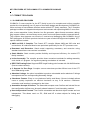
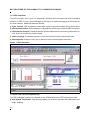
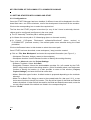
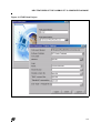
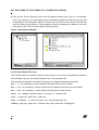
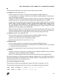
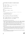
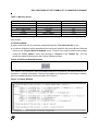
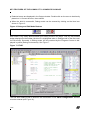
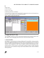
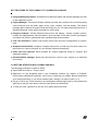
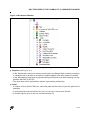
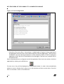
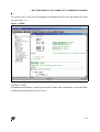
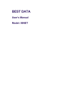
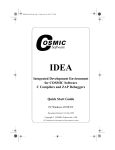
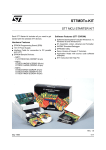
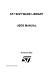
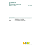
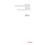
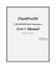
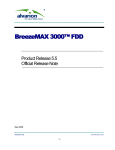
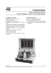
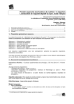
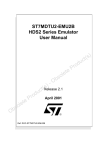
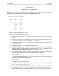
AN983 APPLICATION NOTE KEY FEATURES OF THE COSMIC ST7 C-COMPILER PACKAGE by Microcontroller Division Application Team INTRODUCTION COSMIC Software is a privately-owned company founded in 1983 in Paris, France by Dr. Maurice Fathi and Jean-Pierre Lavandier, two engineers experienced in UNIX systems and embedded development tools. COSMIC develops among other things C compilers and debuggers for ST7 8-bit microcontrollers. The purpose of this application note is to explain how to get started with the C COSMIC tool chain and the ST Visual Debugger developed by ST (STVD7) or the IDE (Integrated Development Environment) developed by COSMIC (IDEA: Integrated Development Environment for Embedded Applications) using ST7 microcontrollers. The following operating systems are supported: Windows 95, 98, NT. If you need more information about these debuggers, please refer to the ST Visual Debug User Manual included with the software in a .pdf version or to the IDEA Quick Start User Manual also included with the software. A complete on-line help service is also available through the Help menu in the STVD7 program. On the COSMIC Internet site (http://www.cosmic-software.com), demo versions of all the following described tools can be downloaded. The files described in this application note plus the corresponding source files are provided in a downloadable .zip file along with this note on the ST MCU internet site (http://mcu.st.com) or on the “MCU ON CD” CD-ROM. AN983/0800 1/18 1 KEY FEATURES OF THE COSMIC ST7 C-COMPILER PACKAGE 1 C COSMIC TOOLCHAIN 1.1 C COMPILER FEATURES COSMIC’s C cross compiler for the ST7 family is part of a complete and uniform compiler product line incorporating over 15 years of innovative design and development. COSMIC’s familiar and easy-to-use software interface works with all ST7 family members. The C Compiler package includes an integrated development environment with optimizing ANSI-C cross compiler, macro assembler, linker, librarian, hex file generator, object format converters, debugging support utilities, run-time library source code, and a multi-pass compiler command driver. The compiler also supports non-intrusive C source-level debugging with COSMIC’s line of ZAP debuggers. All Cosmic products include one year of technical support and updates. ST7specific features include: ■ ANSI and ISO C Compiler: The Cosmic ST7 compiler follows ANSI and ISO rules and conventions. All code and libraries are optimized specifically for the ST7 processor core. ■ Reentrant and Recursive: Stack model supporting reentrancy and recursion using standard stack frame conventions is available. ■ Static Models: Static models provide flexibility and improved efficiency for certain ST7 family members. ■ In-line Assembly: The compiler provides three convenient methods for adding assembly code inside a C program. An argument-passing mechanism is included. ■ IEEE-754 Floating Point: Supports IEEE single floating point formats with full ANSI libraries (Source code included). ■ C Support for Zero Page: Compiler source extensions provide efficient use of the ST7 short addressing mode. ■ Absolute Listings: An option is available to produce relocatable and/or absolute C listings interspersed with the corresponding Assembly listings. ■ Checksum Feature: Easy to use checksum facility and library (Source included) allows users to quickly implement an efficient checksum on any or all sections. Checksum calculation and insertion is managed by the linker. ■ Assembler Accepts C Defines: The assembler accepts most C define and include files so that configuration defines may be easily shared between C and Assembly modules. ■ Host Independent Formats: The Cosmic relocatable and absolute object formats are host independent. This allows user’s on PC, SUN and HP to share objects for linking and debugging. 2/18 2 KEY FEATURES OF THE COSMIC ST7 C-COMPILER PACKAGE ■ IEEE-695 and ELF/DWARF Debug Support: The Cosmic compiler suite supports the IEEE and ELF DWARF standard debug formats used by many popular emulators and logic analyzers. ■ In-Circuit Emulator Compatibility: Cosmic’s ST7 compiler is compatible with STMicroelectronics emulators. ■ Flexible Compiler Interface: Cosmic compilers are designed to be powerful and flexible so they can be used with virtually any environment. Use Cosmic’s own IDEA interface, STVD7 or your favorite editor, make utility and/or source code control system. ■ Memory models: 7 different memory models (see documentation) for maximum optimization of the applied user application through the efficient sharing of memory locations. ■ 2 New options: One for removal of dead assignment code and one that is useful for Flash reprogrammation which is used to copy and execute ROM functions in RAM. 1.2 COSMIC DEBUGGER: ZAP ZAP is a full featured source-level debugger available for Windows and OSF Motif. ZAP’s intuitive graphical interface is uniform for all targets and execution environments. ZAP is available in Simulation (SIM), STMicroelectronics Development Kit and HDS2 in-circuit Emulator configurations. All ZAPs include: ■ ANSI C Debugging: Provides easy access to any C object including Enums, Bit Fields, Structs, Floats, Strings etc. ■ Assembly Source Debugging: Debug mixed C and Assembly applications at the C or Assembly source level including coordinated source and disassembly displays. ■ Non intrusive "Optimizer On" Debugging: ZAP does not modify or augment the user code in any way. The code used by ZAP is the same optimized code that will be used in the final product. All debug symbols are stored in a separate section on the host (e.g. PC). Debug symbols are never stored on the target. ■ Automated Testing: In addition to the graphical interface, ZAP offers a robust command and scripting language which can be used to create automated test scripts including: – Record and Playback - Save a debugging session and play it back later – Multiple File Simulated I/O - Interactively open, read and write to multiple input and output files on the host system. ■ Source Browsing: Browse and set breakpoints in any source windows. ■ On-line Help: Includes Using ZAP, C Language Syntax and C Library functions to provide a complete debugging environment on the host. 3/18 KEY FEATURES OF THE COSMIC ST7 C-COMPILER PACKAGE 1.2.1 ZAP Simulator The ZAP simulator (see Figure 1.) integrates a software CPU simulator with all the standard features of ZAP C source-level debugger to provide a complete debugging environment on the host machine. Additional features include: ■ Cycle Counter: ZAP accurately counts MCU cycles to provide valuable timing information. ■ Interrupt Simulation: ZAP provides a configurable mechanism to simulate MCU interrupts. ■ Performance Analysis: Graphical Display shows code execution and timing information on a file-by-file or function-by-function basis. ■ Code Coverage: Generates reports for code execution and finds unexecuted code. ■ Chronograms: Displays a time-line of function calls to track program execution. Figure 1. ZAP Simulator 1.2.2 ZAP DVP (ST Development Kit) The ZAP debugger interface is available for the STMicroelectronics ST7 Development Kit. ■ High Speed Connection: High Speed parallel port interface provides fast downloads and single stepping. 4/18 KEY FEATURES OF THE COSMIC ST7 C-COMPILER PACKAGE ■ Real-time Debugging: ZAP for ST7 Development Kit provides a low cost real-time debugging environment. ■ Hardware Breakpoints: ZAP provides efficient use of the Development kits’ Hardware breakpoint facility. 1.2.3 ZAP HDS2 (ST Emulators) The ZAP debugger interface is available for the STMicroelectronics HDS2 in-circuit emulator. This solution provides all of the features available with the development kit with the following additional features: ■ Logic Analysis Features: ZAP provides efficient use of the Logic Analysis features of the HDS2 emulator. ■ Complex Event Triggers: Set multiple complex events and triggers to stop or record realtime execution data. Also records and displays time stamp data. ■ Real-time Trace: Flexible trace feature displays recorded trace data in several formats including raw cycle data, C source, disassembly, and C source interspersed with the corresponding disassembly. Export any trace format to a file for post processing and documentation. 2 STVD7 AND C COSMIC TOOLCHAIN 2.1 STVD7 DESCRIPTION The STVD7 is the brand new debugger developed by STMicroelectronics, which replaces the WGDB7 and which is still free of charge. This is an IDE (Integrated Development Environment) which means that the same graphical Windows interface can be used for both editing and debugging. The most recent version of the STVD7 Debugger can be downloaded from the 8-bit MCUs Internet site (http://mcu.st.com at the Free Software page) or from the MCU ON CD CD-ROM. The WGDB7 is still available at the same Free Software page. The STVD7 can be used with 3 different toolchains: ■ ST Assembly toolchain ■ C COSMIC toolchain ■ C HIWARE toolchain The toolchain is selected in the “Project Settings” window as described in Section 2.2.1. Please, refer to Application Note AN978 (“STVD7 Key Features”) or to the STVD7 User Manual for more information about STVD7 features. 5/18 KEY FEATURES OF THE COSMIC ST7 C-COMPILER PACKAGE 2.2 GETTING STARTED WITH COSMIC AND STVD7 2.2.1 Configurations Once the STVD7 Debugger has been installed, 3 different icons will be displayed in the Windows Start menu: one for the simulator, one for the development kit and one for the emulator. Click on the corresponding icon to select the required tool. The first time the STVD7 program is launched (i.e. any of the 3 icons is selected), the toolchains must be configured (configure only the ones used): ■ The ST Assembly Toolchain path is already specified, ■ for Hiware the correct path is C:\Hiware\prog (demo or licensed version), ■ for Cosmic: C:\Program Files\cosmic software\st7eval\cxst7 (demo version) or C:\COSMIC\ST7 (licenced version) if the default paths were selected during the install procedure. Click on the Browse button in this window to select the correct path. Once STVD7 has been launched, a new workspace (*.wsp) must be created: ■ Click on “File, New Workspace” and enter the requested information (see Figure 2.): – Workspace Filename: Assign a name to the workspace, – Workspace location: Use the Browse function to identify the working directory. Then, click on Next and enter the Project Settings: – Software Toolchain: Select C Cosmic, – Executable Filename: Name the downloadable emulator file (.elf created by the CVDWARF utility) used to launch the debug session. (If this file already exists, use the browse function to identify its location.) It is also possible to return to this window (“Project, Project Settings”) and enter this field at a later time. – Maker: Select the type of maker. A default maker is proposed depending on the toolchain selected. – Make File or Batch File: Assign a name to the created batch file (.bat, see 2.2.2), or use the browse function to identify its location. This file will be linked to the Build and Rebuild buttons by default. If other files will be used for the Build and Rebuild commands, enter the correct name instead of the default one listed in the corresponding line. Click on “Finish”. 6/18 KEY FEATURES OF THE COSMIC ST7 C-COMPILER PACKAGE Figure 2. STVD7 New Project 7/18 KEY FEATURES OF THE COSMIC ST7 C-COMPILER PACKAGE ■ Click on the “Source Directory” tab in the Workspace window (see Figure 3.) and doubleclick on the directory: the working directory is selected by default and the list of source files is displayed in the workspace window. Double-click on the file to be edited. New files can also be created in this window. This workspace window is displayed by default on the lefthand side of the STVD7 window (Edit or Debug modes). Figure 3. Workspace Window The project has been created. 2.2.2 Cosmic Batch File (.bat) The Cosmic batch file contains all the tool call functions. It is used to automatically call all the tools needed to get the .elf debug file and/or the .s19 executable file. The following list describes the batch file given in the attached example (pwm.bat): del *.o : not mandatory, used to delete all the object files at each rebuild del *.st7: not mandatory, used to delete the file created by the linker at each rebuild del *.elf: not mandatory, used to delete the debug file at each rebuild cxst7 -vl +debug +modsl main.c vector.c : compiler call clnk -o pwm.st7 pwm.lkf : linker call chex -e 0xe000 -o pwm.s19 pwm.st7 : hex file generator call cvdwarf pwm.st7 pwm.elf : cvdwarf utility call to obtain the .elf debug file 8/18 KEY FEATURES OF THE COSMIC ST7 C-COMPILER PACKAGE The following list describes the various tools and how they are called: ■ Compiler (creates object files: .o): – cxst7 is its name (cxst7.exe is contained in the installed COSMIC directory) – -vl is equivalent to -v (verbose: used to see the different compiler passes) -l (used to generate a relocatable listing file). – +debug: this option is used to generate debug information (required for debugging the application with an ST7 emulator) without increasing the application size of course! – +modsl: this is the selected memory model (there are 5 static models which do not use the stack: +modc, +modm, +modms, +modmm, +modml and 2 stack models: +mods, +modsl). The required model depends on the application, the location of the variables and whether the stack is used or not, but generally speaking, the +modmm model is the one advised for ST7 and medium-size applications. – Then of course the name of all the source files: shown are the main.c and vector.c files. Different compiler options can be applied to source files, then cxst7 has to be called several times with each time the right options and the corresponding source files. ■ Linker (link all the .o to create the .st7): – clnk is its name (clnk.exe is contained into the installed COSMIC directory) – -o pwm.st7: writes output to the specified file (pwm.st7 here) – pwm.st7: name given to the file created by the linker – pwm.lkf: linker parameter file (see Section 2.2.3) ■ Hex generator: – chex is its name (chex.exe is contained in the installed COSMIC directory) – -e: entry point address (corresponds to the beginning of the PROM section: here 0xe000) – -o: output file name (here pwm.s19) – pwm.st7: file created by the linker and converted in pwm.s19 by the hex utility ■ Cvdwarf: – cvdwarf is its name (cvdwarf.exe is contained in the installed COSMIC directory with the other tools or has to be requested from COSMIC) – pwm.st7: file created by the linker and converted into pwm.elf by the cvdwarf utility For more information on all these options and tools, please refer to the IDEA User Guide or IDEA Quick Start Manual included with the COSMIC software or downloadable from their Internet site (http://www.cosmic-software.com). 2.2.3 Linker Parameter File (.lkf) The linker file contains all the parameters used by the linker to create the .st7 file. The following list describes the linker file given in the attached example (pwm.lkf): +seg .text -b 0xe000 -n .text # program start address +seg .const -a .text # constants follow code 9/18 KEY FEATURES OF THE COSMIC ST7 C-COMPILER PACKAGE +seg .bsct -b 0x80 # zero page start address +seg .ubsct -n iram# uninitialized zero page +seg .data -b 0x100 -m 0x0C0 # startup routine "C:/Cosmic/ST7/Lib/crtsx.st7" main.o +seg .const -b 0xffe0 -n vector vector.o # float and integer library names depend on the model used "C:/Cosmic/ST7/Lib/libisl.st7" "C:/Cosmic/ST7/Lib/libm.st7" # define the __stack symbol for stack models only +def __stack=0x100 # stack page (stack models) # define these symbols if crtsi or crtsx is used +def [email protected]# end @ of uninitialized zpage +def [email protected]# end @ of bss segment Lines beginning with a “#” are comments lines. ■ +seg: redefine the different default sections, give them a name, a length, a beginning address... The way to redefine them is the following: +seg section -b start@ -m maxsize -n name (-e end@)...The default sections are .bsct, .ubst, .data, .bss (see Table 1.) ■ include the startup routine (here crtsx.st7 which is used for models: +modml and +modsl), this is not mandatory of course: the user can write his own startup routine. ■ main.o, vector.o: the list of all object files (separated by at least a blank space or a carriage return) to link. ■ libraries: here libisl.st7 (standard C modules containing integers) because of the +modsl memory model (otherwise, choose among libim, libiml, libis, libic, libimm, libims depending on the chosen memory model) and the libm.st7 (mathematic routines in C) models. ■ definition of the stack section because +modsl is a stack model (stack begins here at address 0x100). ■ +def __memory=@section: give the beginning (if loaded before first module) or end address of the section (if loaded after last module). 10/18 KEY FEATURES OF THE COSMIC ST7 C-COMPILER PACKAGE Table 1. Memory Areas What? Initialized data Initialized data Non-initialized data Non-initialized data Code Constant Where? Zero page Long range Zero page Long range PROM RAM or PROM Corresponding Name .bsct .data .ubsct .bss .text .const For more information about the linker parameter file (.lkf), please refer to the COSMIC IDEA User Guide. 2.2.4 Debug Mode ■ New source files can of course be created through the “File, New text file” menu. ■ In order to build when all the application files have been created, click on the Build or Rebuild button on the “Project, Build or Rebuild” menu. These 2 icons may be added to the toolbar using the “Tools, Option” menu and clicking on “Project” in the Toolbar tab. This will launch the batch file selected in the Project Settings window. Figure 4. Build and Rebuild Buttons The results of all operations, debug messages and other information (emulator/connection information, run/stop information, warning messages) are displayed in the Output window, which is located below the Source window. See Figure 5. Figure 5. Output Window 11/18 KEY FEATURES OF THE COSMIC ST7 C-COMPILER PACKAGE ■ Detected errors are displayed in the Output window. Double-click on the error to be directly placed on it. Correct the error, then rebuild. ■ When the build is successful, Debug mode can be entered by clicking on the blue icon shown in Figure 6. Figure 6. Debug and Edit Mode Buttons Edit mode is very easily differentiated from Debug mode in two ways. First, by the pressed button displayed in the toolbar (the blue D is highlighted when in Debug mode or the red cross for Edit mode). Secondly, in Debug mode, the line reached by the Program Counter is displayed in yellow (Debug environment). See Figure 7. Figure 7. STVD7 The first time Debug mode is entered, the information in the “MCU Configuration” window must be entered (see Figure 8.): 12/18 KEY FEATURES OF THE COSMIC ST7 C-COMPILER PACKAGE ■ MCU name ■ CPU frequency ■ LVD (on, off, level) ■ Watchdog (hardware or software)... In this window are contained all the possible MCU configurations that are set through the option byte or certain registers when working with the MCU. Figure 8. MCU Configuration Window 3 COSMIC IDE FOR ST7: IDEA The C COSMIC toolchain can also be used with the IDE delivered automatically with the compiler: IDEA. Then for debugging, either the STVD7 or ZAP tools can be chosen. 3.1 IDEA FEATURES All COSMIC C Cross Compilers for Windows 95/98 and NT include IDEA - Cosmic’s own Windows 32-bit integrated development environment which is preconfigured for the ST7 family of processors. IDEA is specifically designed for developing embedded applications with Cosmic compilers. IDEA integrates an editor, project manager, graphical smart build/make facility, program analyzer, link file generator, documentation manager and ZAP or STVD7 debuggers into one easy to use environment running under Windows 95/98 and NT4. IDEA includes the following features: 13/18 KEY FEATURES OF THE COSMIC ST7 C-COMPILER PACKAGE ■ Integrated Windows Editor: Windows 32-bit MS-style editor with syntax highlights for both C and assembly source. ■ Project Manager: Convenient Project window provides easy access to the most frequently used functions such as make, build, touch, mark, compile, link and debug. The project manager also supports Drag and Drop technology so you can select and drag files from a Windows Explorer to the project manager for easy setup. ■ Program Analyzer: Intuitive Explorer-style source file display - shows compiler options, include file dependencies, file build status, time and date of last edit, function prototypes, command line defines, global and static variables and documentation. ■ Link File Generator: Flexible Link builder offers point and click configuration of memory map. ■ Graphical Smart Build: Configure Compiler and Linker to build only files that need to be rebuilt and run various compiler or user defined utilities automatically. ■ Point and click Options: IDEA provides an intuitive graphical setup for compiler and assembler options. ■ Documentation manager: Attach any documents or notes to your project or to individual source files. 3.2 GETTING STARTED WITH COSMIC AND IDEA The following procedure is used for IDEA: ■ Open IDEA and click on “Project, New” ■ Right-click on the proposed path in the workspace window (by default: C:\Program Files\cosmic software\st7eval\cxst7, see Figure 9.) and click on Update. Browse and select your working directory. If you chose another path, change it in pwm.lkf (see 2.2.3). ■ Put all .c files in the “Files” directory in the workspace window (right-click on Files and select Add file) so that you’ll be able to use the make and/or the build tools. ■ To edit your files, right-click on the file to be edited and select Edit. 14/18 KEY FEATURES OF THE COSMIC ST7 C-COMPILER PACKAGE Figure 9. Workspace Window You also have to configure all the tools by right-clicking on them and select Options: ■ Compiler (see Figure 10.): – In the General tab: select one memory model (the Long Range Stack model for example), in verbose mode to be able to see all the compiler passes, and other options if needed. – In the Miscellaneous tab: select generate debug information to be able to debug your application with ZAP or STVD7. – The other tabs are for optimization options or generating a listing file. ■ Linker: – In Output to file: with the FIND icon, select the path and the name of your file (pwm.st7 for example) – In Command file: select the linker file (.lkf). It’s up to the user to write this file. – In Create map file: give a name to the desired map file. 15/18 KEY FEATURES OF THE COSMIC ST7 C-COMPILER PACKAGE Figure 10. Tool Configuration ■ Builder: – Check the “Run user utility 1 ” box and type: “cvdwarf appli.st7 appli.elf” where appli has to be replaced of course by the correct names relative to the user application. This tool is the CVDWARF convertor which generates the .elf file needed by ZAP or STVD7 to debug the application (that’s the file to download into the debugger). Add this tool (cvdwarf.exe) to the default ones. When all parameters are configured and all the application files have been written, build the application by clicking on the Build icon: If errors occur, they will be displayed on a dedicated window. In order to be automatically placed on errors, double click on the error in this window and then correct them. Once the error is corrected, re-click on the Build icon. 16/18 KEY FEATURES OF THE COSMIC ST7 C-COMPILER PACKAGE If no errors occur, a “No errors” message will be displayed on the menu bar below the source file (see Figure 11.) Figure 11. IDEA Choose the debugger you want to use in the Tools in the workspace window and then launch it (STVD7 or ZAP). For additional information, contact your nearest ST sales office or distributor, or visit the STMicroelectronics web site at http://mcu.st.com. 17/18 KEY FEATURES OF THE COSMIC ST7 C-COMPILER PACKAGE "THE PRESENT NOTE, WHICH IS FOR GUIDANCE ONLY, AIMS TO PROVIDE CUSTOMERS WITH INFORMATION REGARDING THEIR PRODUCTS IN ORDER FOR THEM TO SAVE TIME. AS A RESULT, STMICROELECTRONICS SHALL NOT BE HELD LIABLE FOR ANY DIRECT, INDIRECT OR CONSEQUENTIAL DAMAGES WITH RESPECT TO ANY CLAIMS ARISING FROM THE CONTENT OF SUCH A NOTE AND/OR THE USE MADE BY CUSTOMERS OF THE INFORMATION CONTAINED HEREIN IN CONNEXION WITH THEIR PRODUCTS." Information furnished is believed to be accurate and reliable. However, STMicroelectronics assumes no responsibility for the consequences of use of such information nor for any infringement of patents or other rights of third parties which may result from its use. No license is granted by implication or otherwise under any patent or patent rights of STMicroelectronics. Specifications mentioned in this publication are subject to change without notice. This publication supersedes and replaces all information previously supplied. STMicroelectronics products are not authorized for use as critical components in life support devices or systems without the express written approval of STMicroelectronics. The ST logo is a registered trademark of STMicroelectronics 2000 STMicroelectronics - All Rights Reserved. Purchase of I2C Components by STMicroelectronics conveys a license under the Philips I2C Patent. Rights to use these components in an I2C system is granted provided that the system conforms to the I2C Standard Specification as defined by Philips. STMicroelectronics Group of Companies Australia - Brazil - China - Finland - France - Germany - Hong Kong - India - Italy - Japan - Malaysia - Malta - Morocco - Singapore - Spain Sweden - Switzerland - United Kingdom - U.S.A. http://www.st.com 18/18