1
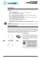
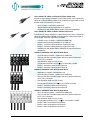
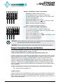
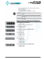
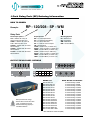
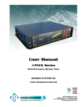
User Manual
J-PACK Series
Hi-Power Relay Pack
JOHNSON SYSTEMS INC.
WWW.JOHNSONSYSTEMS.COM
Contents
Warranty...........................................................................................................2
Introduction.......................................................................................................3
Characteristics..................................................................................................4
Installation........................................................................................................6
Mounting Options.............................................................................................6
AC Power Supply Input Options.......................................................................8
Output Connector/Receptacle Options...........................................................10
Output Connector/Receptacle Diagrams........................................................13
Control Input...................................................................................................14
DRD-6 Controller............................................................................................15
DRD Relay PDB.............................................................................................15
User Interface.................................................................................................16
System Status • LED Indicators ....................................................................17
System Status • LCD Display.........................................................................18
Quick Programming Reference to System Configuration Menu Items...........19
Detailed Programming of System Configuration Menu Items................ 20
Important Hard-key Information......................................................................28
J-Pack Relay Pack (RP) Ordering Information...............................................29
Warranty
J-PACK Series relay packs come with a standard one (1) year limited
warranty. Extended warranties of up to ten (10) years are available at the
time of purchase.
For details visit: www.johnsonsystems.com/warranties.htm
For Technical Assistance
1. Refer to your product user manual. The most current revision is
available online: www.johnsonsystems.com/literature.htm
2. Contact the “point-of-sale” dealer or distributor from which this product
was originally purchased, and ask for technical assistance.
3. If neither of the above can provide you with the necessary information,
please contact our factory via email ([email protected])
or phone (403-287-8003) during business hours (Monday to Friday,
8:00AM to 5:00PM MST).
2
WWW.JOHNSONSYSTEMS.COM
Introduction
J-PACK Series
Hi-Power Relay Pack
J-PACK Relay Packs are a universal hi-power series of 3 and 6 channel relay
packs rated at a full 20 Amps per circuit. Designed for dry contact and/or DMX
power control of LED fixtures, distributed commercial fluorescent installations or
any environment where fast, precise hi-power control is demanded. J-PACK's
offer versatility in virtually any environment; these commercial grade units
include 120, 208, 240, and 277 volt models. These unique and compact units
can be wall-mounted for permanent installations, 19" rack mounted, pipe
mounted or used as portable units. Multiple units can be easily “ganged”
together for fast system expansion. Long distance communication via DMX512
protocol lowers electrical installation costs and allows for centralized control.
Next generation “system-on-a-chip” technology provides unsurpassed value in
professional grade hi-power switching. Standby power consumption of less than
1 Watt, allows for compliance with the International Energy Agency’s “One Watt
Initiative” for standby power consumption. This makes J-PACK’s truly “green”
with minimal possible impact on the environment!
All circuits contain fully isolated output power relays rated to 50 Amps! Selfcontained units with premium UL489 rated hydraulic magnetic circuit breakers
provide optimum safety while eliminating the need for separate branch circuit
breakers and relay panels. Intuitive LCD user interface combined analog
inputs and contact closure inputs allow for industry wide application. This nextgeneration product helps save our environment as well as time and money.
Features
• Power control via dry contact or DMX512 lighting control protocol.
• Designed for LED fixture power switching.
• Unique power saving standby mode reduces power consumption to less
than 1 Watt, a “green” power management product.
• Heavy-duty “airgap” output relays rated to 50 Amps!
• DMX512 start addressable in single channel (offset) or individually (patch).
• Programmable DMX Status Hold timeout.
• Dual auxiliary contact inputs permits power management interface with
BMS, photocells, occupancy sensors, HVAC, security and audio.
• Dry contact activated relay sequencing for special effects.
• LCD user interface for easy setup and monitoring.
• Keypad lockout prevents unauthorized access.
• Over-heat and over-current protected.
• Available in various voltages, output and mounting configurations.
• ETL Listed, compliance with UL508 and CSA 22.2.
• Up to 10 year product warranty available.
WWW.JOHNSONSYSTEMS.COM
3
Characteristics
• Power Termination & Maximum Feeder Capacity:
RP-120-ED-*XX
6 circuits totaling 1,800W
RP-120HO-ED-*XX
6 circuits totaling 3,600W
RP-120/240-SP-XX
6 circuits totaling 14,400W
RP-120/240-TL-XX
6 circuits totaling 14,400W
RP-120/240-SO-XX
6 circuits totaling 14,400W
RP-120/240-TB-XX
6 circuits totaling 14,400W
RP-120/208-SP-XX
6 circuits totaling 14,400W
RP-120/208-TL-XX
6 circuits totaling 14,400W
RP-120/208-SO-XX
6 circuits totaling 14,400W
RP-120/208-TB-XX
6 circuits totaling 14,400W
RP-120/208-TL208-XX
3 circuits totaling 12,480W
RP-120/208-SO208-XX
3 circuits totaling 12,480W
RP-120/208-TB208-XX
3 circuits totaling 12,480W
RP-120/240-TL240-XX
3 circuits totaling 14,400W
RP-120/240-SO240-XX
3 circuits totaling 14,400W
RP-120/240-TB240-XX
3 circuits totaling 14,400W
RP-277/480-TB277-WM
3 circuits totaling 16,620W
* Not available in wall mount (WM)
•Environment
• Temperature Range: 23°F (-5°C) to 104°F (40°C) ambient.
• Humidity Range: 0% to 90% non-condensing.
• Load Type:
• Six 120V single phase 50/60 Hz circuits for AC Loads Only.
• Rated for 20A General Purpose and 20A Tungsten.
• Switch Type: “Airgap” power relay rated 1 million operations minimum at 50 Amps 240VAC.
• Isolation: 4,000 Volts minimum per circuit.
• Physical: 10" x 17" x 3.4" (25.4 cm x 43 cm x 8.5 cm).
• Weight: 12 - 13 lbs. (5.5 - 6.0 Kg) depending on model.
• Material: 18-gauge steel CRS.
• Finish: Hammer texture black powder coat.
Front View
Control Input
XLR Connectors
Refer to
page 14 for details
User Interface
Refer to page 16 for details
4
WWW.JOHNSONSYSTEMS.COM
Circuit Breakers
Left Side View
Air Intake Fan
Rubber Feet
(For RF model only)
Right Side View
Handle
Air Exhaust
Ventilation
Top View
Air
Intake
Four (4) Safety Cable Mounting Holes
(For PM model only)
Safety Cable supplied
on PM model
Air
Exhaust
Four (4) Indents
(For vertical stacking)
Ten (10) SEMS #6-32 x 3/8" Philips Pan Head, Top Panel (Lid) Mounting Screws
Six (6) #6-32 x 3/8" Philips Flat Head, Top Panel (Lid) Mounting Screws
Four (4) SEMS #6-32 x 3/8" Philips Pan Head, Rack Mount Bracket Mounting Screws
WWW.JOHNSONSYSTEMS.COM
5
Installation
J-Pack Series relay packs are intended for indoor use only, in a controlled environment at a room
temperature.
•
•
•
•
•
Mount in a suitable location.
Refer to the Mounting Options section on page 6 for applicable details.
Connect the applicable AC power supply input.
Refer to the AC Power Supply Input Options section on page 8 for applicable details.
Connect the relay output receptacles/terminals.
Refer to the Relay Output Connection Options section on page 10 for applicable details.
Connect DMX and/or dry contact control input(s).
Refer to the Control Input section on page 14 for details.
Program, setup, test and verify functionality.
Refer to the Detailed Programming of System Configuration Menu Items section on page
20 for details.
WARNING: For indoor use only!
Mounting Options
J-PACK Series relay packs are capable of various mounting options to suit the application required.
A cooling fan mounted inside the relay pack is used to move air through the chassis and cool the
internal components. The fan automatically turns on whenever a relay is on and automatically turns
off when all relays are off. There is a 5 minute timeout for the fan to turn off to ensure the internal
components are cooled sufficiently. It is important to mount the dimmer pack in the orientation
intended with unobstructed ventilation to ensure adequate cooling.
RF = Rubber Feet
For portable applications, the relay pack can be
set on any flat surface. Rubber feet are mounted
on the bottom of the relay pack, with indents on
the top cover panel to facilitate vertical stacking
of up to 6 units high.
WARNING: Never place the relay packs side
by side (horizontally) without
a minimum of 12” of clearance
between them. Always leave a
minimum of 6” of clearance from
the relay packs air intake and
exhaust. Failure to comply may
cause thermal overheating.
6
WWW.JOHNSONSYSTEMS.COM
PM = Pipe Mount
For pipe mounting, a bracket, C-clamp and safety cable
are provided and must be used to secure the relay pack to
standard pipe sizes from 1" to 2" (1.25" to 2.375" outside
diameter).
WARNING: Ensure the pipe is secure and rated
adequately for local rigging codes.
Ensure the safety cable is fastened correctly
to secure the relay pack.
WM = Wall Mount
For permanent applications, the relay pack can be
mounted to any wall surface capable of supporting its
weight. Using the four (4) mounting holes provided, 1/4"
(6mm) screws or bolts are required to fasten and secure
the rack safely to the wall.
WARNING: Never place the relay packs side by side
(vertically) without a minimum of 12” of
clearance between them. Always leave a
minimum of 6” of clearance from the relay
packs air intake and exhaust. Failure to
comply may cause thermal overheating.
RM = Rack Mount
For rack mounting, brackets are provided and used to
secure the relay pack in a standard 19" rack.
WARNING: Ensure there is sufficient ventilation
provided when mounting multiple relay
packs within a 19" rack. The internal
ambient temperature of the rack must not
exceed 104°F (40°C). Failure to comply may
cause thermal overheating.
WARNING: Ensure there is adequate rear support
provided to maintain the relay pack position
inside the 19" rack.
WWW.JOHNSONSYSTEMS.COM
7
AC Power Supply Input Options
J-PACK Series relay packs are capable of various AC power supply input
configurations.
AC Power Supply
Input Terminals
Remove the top panel (lid) of the relay pack chassis to access the contractor
termination area, where the required AC power supply input terminals are
located. To remove the top panel (lid), remove the ten (10) SEMS #6-32 x 3/8"
Philips pan head mountings screws located on the sides and the six (6) #6-32
x 3/8" Philips flat head mounting screws located on the top, using a Philips
#2 screwdriver, and carefully lift the lid up. The cooling fan is mounted on the
lid, so be careful not to strain the fan wiring cable. If the fan cable needs to
be disconnected, carefully cut off the strain relief wire tie and unplug the fan
connector from the J5 PCB connector. Be sure to save the mounting screws to
secure the top panel (lid) once the AC power supply input wiring termination is
complete.
A 1.109" knockout (suitable for 0.75" conduit) located on the rear panel of the
relay pack chassis is provided for wire/conduit entry to the AC power supply
input terminals. Ensure an adequate fitting is used to secure the conduit to the
rear panel. Only use wire rated for the specifications provided. Route the wire
directly from the conduit entry into the power terminals. Use a 3/16" flathead
screwdriver to torque the power terminals to the specifications provided.
Once the AC power supply input wiring termination is complete, carefully
reinstall the top panel (lid). If the cooling fan cable was disconnected, be sure
to reconnect it to the J5 PCB connector, and install a wire tie for strain relief.
Carefully slide the lid down into place, making sure the fan cable does not get
pinched in the metalwork. Secure the lid using the mounting screws previously
removed. To ensure ground continuity between all chassis panels, be sure to
use the SEMS mounting screws with integral star washers on the sides.
WARNING: All wiring must comply with local electrical codes and be
completed by qualified personnel only!
WARNING: For connection use copper wire only, rated for 167ºF (75ºC)
minimum!
WARNING: All AC power supply input options require an external disconnect!
WARNING: Ensure the AC power supply external disconnect is turned off and
locked out while wiring terminations are completed!
WARNING: For permanent installations, the external disconnect must be
located adjacent to the equipment.
AVERTISSMENT: Pour les installations permanentes, le débrancher externe
doit être trouvé adjacent à l'équipement.
8
WWW.JOHNSONSYSTEMS.COM
120 = 120VAC 1Ø 3-Wire via a Single 5' Edison Power Cord
Includes a single factory installed 5' (1.5m) Edison power cord. Connect the
cables to a standard Edison (NEMA 5-15) receptacle, protected with a circuit
breaker rated at a maximum of 15 Amps.
• Up to 15 Amps – maximum 1,800W total.
• Internal electrical wiring termination is not required.
• Available only with Duplex Edison output connectors/receptacles.
120 = 120VAC 1Ø 3-Wire via Dual 5' Edison Power Cord
Includes two (2) factory installed 5' (1.5m) Edison power cords. Connect the
cables to standard Edison (NEMA 5-15) receptacles, each protected with a
circuit breaker rated at a maximum of 15 Amps.
•
•
•
•
•
2 circuits of up to 15 Amps – maximum 3,600W total.
Internal electrical wiring termination is not required.
Relays 1, 3 and 5 are powered from a single power cord.
Relays 2, 4 and 6 are powered from a single power cord.
Available only with Duplex Edison (NEMA 5-15) output connectors/
receptacles.
120/240 = 120/240VAC 1Ø 4-Wire Terminal Block
• Up to 60 Amps per phase – maximum 14,400W total.
• Use wire size #12 to #4 AWG copper wire only, rated for 300V and
167°F (75°C) minimum.
• Strip insulation length to 0.44" (11mm).
• Torque power terminals (A, B, N, ) to 10.5 IN-LBS (1.2 NM).
• Relays 1, 3 and 5 are powered from Phase A.
• Relays 2, 4 and 6 are powered from Phase B.
120/240 = 120/240VAC 1Ø 3-Wire Terminal Block
• Applicable for 240VAC output models only.
• Up to 60 Amps per phase – maximum 14,400W total.
• Use wire size #12 to #4 AWG copper wire only, rated for 300V and
167°F (75°C) minimum.
• Strip insulation length to 0.44" (11mm).
• Torque power terminals (A, B, ) to 10.5 IN-LBS (1.2 NM).
• Relays 1, 3 and 5 are powered from Phase A.
• Relays 2, 4 and 6 are powered from Phase B.
120/208 = 120/208VAC 3Ø 5-Wire Terminal Block
• Up to 40 Amps per phase – maximum 14,400W total.
• Use wire size #12 to #4 AWG copper wire only, rated for 300V and
167°F (75°C) minimum.
• Strip insulation length to 0.44" (11mm).
• Torque power terminals (A, B, C, N, ) to 10.5 IN-LBS (1.2 NM).
• Relays 1 and 4 are powered from Phase A.
• Relays 2 and 5 are powered from Phase B.
• Relays 3 and 6 are powered from Phase C.
WWW.JOHNSONSYSTEMS.COM
9
120/208 = 120/208VAC 3Ø 4-Wire Terminal Block
• Applicable for 208VAC output models only.
• Up to 40 Amps per phase – maximum 12,480W total.
• Use wire size #12 to #4 AWG copper wire only, rated for 300V
and 167°F (75°C) minimum.
• Strip insulation length to 0.44" (11mm).
• Torque power terminals (A, B, C, ) to 10.5 IN-LBS (1.2 NM).
• Relays 1 and 4 are powered from Phase A.
• Relays 2 and 5 are powered from Phase B.
• Relays 3 and 6 are powered from Phase C.
277/480 = 277/480VAC 3Ø 5-Wire Terminal Block
• Up to 20 Amps per phase – maximum 16,620W total.
• Use wire size #12 to #4 AWG copper wire only, rated for 300V
and 167°F (75°C) minimum.
• Strip insulation length to 0.44" (11mm).
• Torque power terminals (A, B, C, N, ) to 10.5 IN-LBS (1.2 NM).
• Relay 1 is powered from Phase A.
• Relay 2 is powered from Phase B.
• Relay 3 is powered from Phase C.
WARNING: Ensure all AC power supply connections are tightened to the torque specification
provided, before turning on the AC power supply!
WARNING: Ensure all chassis panels are secure before turning on the AC power supply!
Output Connector/Receptacle Options
J-PACK Series relay packs are designed for high performance switching for general purpose and
tungsten loads at 120VAC, 208VAC, 240VAC or 277VAC.
120VAC Operation with Factory Installed Single or Dual Edison Power Cord
Capable of switching six (6) 1,800 Watt relay output circuits, fully protected by premium 15 Amp
hydraulic magnetic circuit breakers. Powered with 120VAC 1Ø 3-Wire, each hot leg is switched
independently through six (6) relays, providing 120VAC on each of the output connectors.
J-PACK Series relay packs supplied with a factory installed single (1) Edison power cord are
capable of switching a total of 1,800 Watts shared between the six (6) Duplex Edison output
connectors. J-PACK Series relay packs supplied with factory installed dual (2) Edison power
cords are capable of switching a total of 3,600 Watts shared between the six (6) Duplex Edison
output receptacles.
120VAC Output Receptacle with Factory Installed Single or Dual Edison Power Cord
• ED = 15A Duplex Edison (NEMA 5-15)
120VAC Operation
Capable of switching six (6) 2,400 Watt relay output circuits, fully protected by premium 20 Amp
hydraulic magnetic circuit breakers. Powered with 120/240VAC 1Ø 4-Wire or 120/208VAC 3Ø
5-Wire, each hot leg is switched independently through a relay, providing 120VAC on each of the
output connectors/receptacles.
10
WWW.JOHNSONSYSTEMS.COM
120VAC Output Connector/Receptacle Options
•
•
•
•
SP = 20A Stage Pin (Bates)
TL = 20A Twist Lock Ground (TLG) (NEMA L5-20R)
SO = 19-Pin Socapex
TB = Terminal Block
208VAC Operation
Capable of switching three (3) 4,160 Watt relay output circuits, fully protected
by premium 20 Amp hydraulic magnetic circuit breakers. Powered with
120/208VAC 3Ø 5-Wire, two hot legs (phases) are switched simultaneously
through two relays, providing 208VAC on each of the output connectors/
receptacles.
208VAC Output Connector/Receptacle Options
• TL = 3 x 20A Twist Lock Ground (TLG) (NEMA L6-20R)
• SO = 19-Pin Socapex
• TB = Terminal Block
240VAC Operation
Capable of switching three (3) 4,800 Watt relay output circuits, fully protected
by premium 20 Amp hydraulic magnetic circuit breakers. Powered with
120/240VAC 1Ø 4-Wire, two hot legs (phases) are switched simultaneously
through two relays, providing 240VAC on each of the output connectors/
receptacles.
240VAC Output Connector/Receptacle Options
• TL = 3 x 20A Twist Lock Ground (TLG) (NEMA L6-20R)
• SO = 19-Pin Socapex
• TB = Terminal Block
277VAC Operation
Capable of switching three (3) 5,540 Watt relay output circuits, fully protected
by premium 20 Amp thermal magnetic circuit breakers. Powered with
277/480VAC 3Ø 5-Wire, each hot leg is switched independently through a
relay, providing 277VAC on each of the output connectors.
277VAC Output Connector/Receptacle
• TB = Terminal Block
19-Pin Socapex Connection Details (Pinout)
Pin 1 = Circuit 1 Hot
Pin 2 = Circuit 1 Neutral
Pin 3 = Circuit 2 Hot
Pin 4 = Circuit 2 Neutral
Pin 5 = Circuit 3 Hot
Pin 6 = Circuit 3 Neutral
Pin 7 = Circuit 4 Hot
Pin 8 = Circuit 4 Neutral
Pin 9 = Circuit 5 Hot
Pin 10 = Circuit 5 Neutral
Pin 11 = Circuit 6 Hot
Pin 12 = Circuit 6 Neutral
Pin 13 = Circuit 1 Ground
Pin 14 = Circuit 2 Ground
Pin 15 = Circuit 3 Ground
Pin 16 = Circuit 4 Ground
Pin 17 = Circuit 5 Ground
Pin 18 = Circuit 6 Ground
Pin 19 = Not Used
WWW.JOHNSONSYSTEMS.COM
11
Terminal Block Connection Details
NOTE: This option is intended for permanent installation
application only.
120 VAC Operation
208 VAC and 240 VAC Operation
Remove the top panel (lid) of the relay pack chassis to access
the contractor termination area, where the required relay
output (load) terminals are located. To remove the top panel
(lid), remove the ten (10) SEMS #8-32 x 3/8" Philips pan head
mountings screws located on the sides and the six (6) #8-32 x
3/8" Philips flat head mounting screws located on the top, using
a Philips #2 screwdriver, and carefully lift the lid up. The cooling
fan is mounted on the lid, so be careful not to strain the fan
wiring cable. If the fan cable needs to be disconnected, carefully
cut off the strain relief wire tie and unplug the fan connector
from the J5 PCB connector. Be sure to save the mounting
screws to secure the top panel (lid) once the relay output (load)
wiring terminations are complete.
In suitable locations on the rear panel of the relay pack
chassis, knockout suitable hole sizes for wire/conduit entry to
the output (load) terminals. Ensure an adequate fitting is used
to secure the conduit to the rear panel. Only use wire rated
for the specifications provided below. Route the wire directly
from the conduit entry into the output (load) terminals. Use a
3/16" flathead screwdriver to torque the power terminals to the
specifications provided below.
For 120 VAC operation, each of the six (6) output (load) circuits
require three (3) conductors; one (1) for hot, one (1) for neutral
and one (1) for ground. There are six (6) hot terminals, six (6)
neutral terminals and six (6) ground terminals, one for each
output circuit.
277 VAC Operation
For 208 VAC and 240 VAC operation, each of the three (3)
output (load) circuits require three (3) conductors; two (2) for the
hot legs and one (1) for ground. There are six (6) hot terminals
and three (3) ground terminals, one for each output circuit.
For 277 VAC operation, each of the three (3) output (load)
circuits require three (3) conductors; one (1) for hot, one (1)
for neutral and one (1) for ground. There are three (3) hot
terminals, three (3) neutral terminals and three (3) ground
terminals, one for each output circuit.
Once the relay output (load) wiring terminations are complete,
carefully reinstall the top panel (lid). If the cooling fan cable was
disconnected, be sure to reconnect it to the J5 PCB connector,
and install a wire tie for strain relief. Carefully slide the lid down
into place, making sure the fan cable does not get pinched
in the metalwork. Secure the lid using the mounting screws
previously removed. To ensure ground continuity between all
chassis panels, be sure to use the SEMS mounting screws with
integral star washers on the sides.
12
WWW.JOHNSONSYSTEMS.COM
• Use wire size #12 to #8 AWG copper wire only, rated for 300V and
167°F (75°C) minimum.
• Strip insulation length to 0.4" (10mm).
• Torque connections to 13 - 16 IN-LBS (1.5 - 1.8 NM).
WARNING: For connection use copper wire only, rated for 167°F (75°C)
minimum.
WARNING: Ensure all dimmer output terminal connections are tightened
to the torque specification provided, before turning on the AC
power supply!
WARNING: Ensure all chassis panels are secure before turning on the AC
power supply!
1
2
3
4
5
6
Output Connector/Receptacle Diagrams
ED = 15A Duplex Edison (NEMA 5-15)
1
2
3
4
5
6
• 6 x 120VAC circuits.
• Single or dual Edison power cord option only.
SP = 20A Stage Pin (Bates)
1
2
3
4
5
6
• 6 x 120VAC circuits.
TL = 20A Twist Lock Ground (TLG) (NEMA L5-20R)
• 6 x 120VAC circuits.
SO = 19-Pin Socapex
• 6 x 120VAC circuits.
• 3 x 208VAC circuits.
• 3 x 240VAC circuits.
TB = Terminal Block
1
2
3
•
•
•
•
6 x 120VAC circuits.
3 x 208VAC circuits.
3 x 240VAC circuits.
3 x 277VAC circuits.
TL = 20A Twist Lock Ground (TLG) (NEMA L6-20R)
• 3 x 208VAC circuits.
• 3 x 240VAC circuits.
WWW.JOHNSONSYSTEMS.COM
13
Control Input
J-PACK Series relay packs are equipped with DMX input and thru, as well as two (2) auxiliary
dry-contact inputs. XLR connectors are provided on the front panel of the relay pack chassis, and
breakaway type connectors are provided internally for permanent installation applications.
All control input wiring is classified as CLASS 2 LOW VOLTAGE.
Breakaway type connector termination:
• Use wire size #28 to #12 AWG copper wire only, rated for 167°F (75°C) minimum.
• Strip insulation length to 0.3" (7.5mm).
• Use a 1/8" flathead screwdriver - torque terminations to 3.6 IN-LBS (0.4 NM).
WARNING: For internal connection use copper wire only, rated for 167°F (75°C) minimum.
DMX Input and Thru
•
•
•
•
•
•
•
•
DMX connects to the 5-pin XLR connectors located on the front panel.
DMX alternatively connects to the internal 3-pin breakaway type connectors.
Complies with USITT DMX512-A (ANSI E1.11 - 2008), Standard protocol for digital data control.
Recommended cable is Belden 9829, 9842, Cat 5 or equivalent (low-capacitance, twisted pair).
Wiring must follow a daisy-chain topology.
Maximum of 32 receiving devices on a single DMX line.
Maximum cable length is 1,500 feet (455 meters).
For more information, Google DMX, or visit: http://www.usitt.org/DMX512FAQ.aspx
NOTE: Do not use the front panel XLR and internal DMX connections simultaneously.
Ensure only the last (end-of-line) DMX receiving device is terminated! Refer to menu item
DMX TERM on page 20 for details.
5-Pin XLR Connection Details (Pinout)
Pin 1 = DMX Shield / Common
Pin 2 = DMX DataPin 3 = DMX Data+
Pin 4 = Not Used - Thru Connection
Pin 5 = Not Used - Thru Connection
Auxiliary Dry-Contact Inputs
The auxiliary dry-contact inputs are simply a maintained normally-open switch connection between
the auxiliary input and common. The auxiliary inputs are used to trigger relays on, load shed or
to activate effects. The auxiliary inputs may be interfaced with compatible AV control equipment,
photocells, occupancy sensors and building management systems (BMS). Refer to menu items AUX
TEST, AUX1MODE, AUX2MODE and AUXPATCH on pages 23-25 for configuration details.
3-Pin XLR Connection Details (Pinout)
Pin 1 = Auxiliary Input 1
Pin 2 = Common
Pin 3 = Auxiliary Input 2
14
WWW.JOHNSONSYSTEMS.COM
DRD-6 Controller
The DRD-6 is the central electronic control system (aka brain) for all J-PACK Series relay packs.
WWW.JOHNSONSYSTEMS.COM
DRD-6
DMX
RELAY
DRIVER
REV.1 1216
SERIAL NUMBER
MADE IN CANADA
DRD Relay PDB
All J-PACK Series relay packs contain a DRD Relay PCB, consisting of 6 relays with terminal
block connections for line input and load output for each relay.
WARNING: AC LINE VOLTAGE
SERIAL NUMBER
DRD RELAY PCB
REV.1 1216
WWW.JOHNSONSYSTEMS.COM
WWW.JOHNSONSYSTEMS.COM
15
EXECUTE ESCAPE
MENU
RUN
RxD ERROR
RELAY OUTPUT STATUS
1
2
3
4
5
6
RESET
User Interface
All J-PACK Series relay packs are equipped with a user interface located
on the front panel of the chassis. The user interface provides access to all
programming and configuration settings. System status is easily visible on
the LCD display and LED indicators.
All of the programming is accomplished using four (4) switches. Within a few
minutes, most users will find the menu structure very intuitive and easy to
navigate. All configuration settings are automatically stored into an on-board
EEPROM.
LCD Display
The LCD display is capable of displaying 2 lines of 8 characters. A backlight
automatically comes on when activity is sensed. The LCD contrast can be
easily adjusted for optimum viewing. Refer to menu item “LCD VIEW” on
page 27 for further details.
Programming Switches
The MENU UP/DOWN ( ) switches are used for navigating through the
various system configuration menu items. They also allow for programming
of other specific parameters within a selected menu. Pressing and holding
either switch will speed up the scroll rate, which can be helpful to speed up
the configuration time.
The EXECUTE ( ) switch is normally used to select/enter a menu item,
advance forward within a selected menu item, or toggle between parameters
within a selected menu item.
The ESCAPE ( ) switch is normally used to back up within a selected
menu item one step at a time or exit the menu completely.
The RESET switch has two purposes. First, it allows for quick exit from a
menu item after a programming change and automatically puts the system
into normal run mode. Second, it provides a soft reboot for the systems
microcontroller.
The programming switches are backlit with blue LED’s. The LED’s
automatically turn on when activity is sensed. The LED intensity can be
adjusted in the “LED INT” menu. Refer to page 27 for further details.
NOTE: When the J-PACK Series relay pack is powered up, the menus are
“LOCKED!!” with access only to the basic system configuration
menus, which includes setting the DMX start address as well
as enabling or disabling the end-of-line DMX termination. The
menus need to be “UNLOCKED” to access the advanced
system configuration menus. To toggle between “LOCKED!!”
and “UNLOCKED” press and hold down the EXECUTE and then
ESCAPE switches at the same time for 4-5 seconds.
16
A detailed procedure for programming all system configuration
menu items can be found on page 23 to 27.
WWW.JOHNSONSYSTEMS.COM
System Status • LED Indicators
RUN (Green)
Illuminates when the power is on and the microcontroller status is in normal run mode. The LED
flashes once every 2 seconds when the system is in STANDBY mode.
RxD (Yellow)
Illuminates when valid DMX is received. Flashes when invalid DMX is received.
ERROR (Red)
Illuminates whenever an error is sensed. The error type is displayed on the LCD.
6 x RELAY OUTPUT STATUS (Blue)
Illuminates when the corresponding relay (1 thru 6) is in the “on” state. The LED intensity can be
adjusted in the “RLY INT” menu. Refer to page 27 for further details.
NOTE: When operating in 208/240V mode, the relays are paired (1&2, 3&4, 5&6) and there
are 3 output circuits. Relay output status indicators 1 and 2 represent output circuit 1.
Relay output status indicators 3 and 4 represent output circuit 2. Relay output status
indicators 5 and 6 represent output circuit 3.
WWW.JOHNSONSYSTEMS.COM
17
System Status • LCD Display
When DMX is being received, the top line of the LCD display shows the DMX start address
(“DMX:001” to “DMX:512”), unless the system is in DMX patch mode, then “DMX:PAT” is
displayed. When DMX is not being received, the top line of the LCD display shows “DRD-6”,
unless the system is in standby mode, then “STANDBY!” is displayed. The bottom line of the LCD
display shows the current status of the system unless the system configuration menu items are
being accessed. Below are descriptions for each status indication.
NO RX!
Displayed when DMX is not being received and the system is not in scene mode.
XXX
Displayed when valid DMX is being received and is not terminated. “XXX” represents the number
of channels being received in each packet of data. For example, if the system is receiving 512
channels will show “512”.
XXX TERM
Same as above, except “TERM” is shown to indicate if the DMX input is terminated. For example,
if the system is receiving 48 channels of DMX control and is terminated, the display will show
“048 TERM”. Refer to menu items “DMX TERM” on page 20 for further details.
SH XX:YY
Displayed when DMX is disconnected and the systems predetermined DMX status hold (SH) time
is counting down. “XX” represents minutes while “YY” represents seconds. Refer to menu item
“SH TIME” on page 22 for further details.
INF HOLD
Displayed when DMX is disconnected and the systems predetermined DMX status hold (SH) time
is set for infinite (INF) hold. Refer to menu item “SH TIME” on page 22 for further details.
DMX ERR!
Displayed when the system detects a DMX error due to reversed data lines.
OVERTEMP
Displayed when the microcontroller senses an internal over-temperature condition of 185°F
(85°C) or more. All relay outputs are pulsed off until the temperature cools down to 178°F (81°C)
or less. Refer to menu item “CTL TEMP” on page 26 to view the microcontroller temperature.
LOCKED!!
When the J-PACK Series relay pack is powered up, the menus are “LOCKED!!” with access only
to the basic system configuration menus, which includes setting the DMX start address as well
as enabling or disabling the end-of-line DMX termination. The menus need to be “UNLOCKED”
to access the advanced system configuration menus. To toggle between “LOCKED!!” and
“UNLOCKED” press and hold down the EXECUTE and then ESCAPE switches at the same time
for 4-5 seconds.
18
WWW.JOHNSONSYSTEMS.COM
Quick Programming Reference
to System Configuration Menu Items
Basic Menus
1. ADDRESS
2. DMX TERM
Set the DMX start address.
Enable or disable the DMX termination.
Advanced Menus
3. RLY TEST
4. DMX O/P
5. DMX PAT
6. SH TIME
7. TRIGGER LEVEL
8. EFFECTS
9. AUX TEST
10. AUX1MODE
11. AUX2MODE
12. AUXPATCH
13. VOLT SEL
14. CTL TEMP
15. HARD-KEY
16. SERIAL#
17. FIRMWARE
18. DEFAULTS
19. RLY INT
20. LED INT
21. LCD VIEW
Test the relay outputs one at a time, or all at once.
Configure the on-board DMX protocol manager for offset or patch mode.
Patch each of the 6 relay outputs to any DMX input channel.
Set the DMX status hold time from 0 to 99 minutes or infinite.
Set the DMX trigger level threshold for each relay.
Activate effects mode and configure a pattern effect with selectable time.
Test the auxiliary dry-contact inputs.
Set the auxiliary input 1 mode to trigger relays on, load shed or activate effects.
Set the auxiliary input 2 mode to trigger relays on, load shed or activate effects.
Configure and patch each of the 6 relay outputs to the auxiliary inputs.
Select the relay output circuit operating voltage.
View the temperature of the microcontroller.
View the microcontroller’s unique eight-character hard-key code.
View the microcontroller’s unique eight-character silicone serial number.
View the microcontroller’s firmware version.
Set various system configuration settings to the factory default.
Set the intensity of the relay output status LED’s.
Set the intensity of the programming switch LED’s.
Adjust the contrast of the LCD Display for optimum viewing.
WWW.JOHNSONSYSTEMS.COM
19
Detailed Programming
of System Configuration Menu Items
NOTE: When the J-PACK Series relay pack is powered up, the menus are “LOCKED!!” with
access only to the basic system configuration menus, which includes setting the DMX
start address as well as enabling or disabling the end-of-line DMX termination. The
menus need to be “UNLOCKED” to access the advanced system configuration menus.
To toggle between “LOCKED!!” and “UNLOCKED” press and hold down the EXECUTE
and then ESCAPE switches at the same time for 4-5 seconds.
The sequence of the following system configuration menu items appear as the MENU DOWN (
switch is pressed. Pressing the MENU UP ( ) switch will sequence the system configuration
menu items in the opposite order. Pressing and holding either of the MENU UP/DOWN ( )
switches will speed up the scroll rate, which can be helpful to speed up the configuration time.
Basic Menus
20
1. ADDRESS
DMX>001 DMX>512 DMX>001
Set the DMX start address.
The DMX start address can be assigned from 001 to 512.
Press EXECUTE to enter the menu.
Displays the current DMX start address for both DMX inputs.
Press MENU ( ) to modify and select the desired DMX start address.
Press both MENU ( ) simultaneously to toggle to DMX start address 001.
Press ESCAPE to exit the menu and save the selected DMX start address.
Press RESET to exit the menu without saving.
The menu will automatically timeout after 2 minutes of inactivity and save.
NOTE: DMX O/P must be set to OFFSET mode for this menu to function.
2. DMX TERM ENABLED
DISABLED
Enable or disable the DMX termination.
Activates and deactivates a 120Ω termination resistor. DMX termination is indicated
on the LCD display when DMX is being received. When the DMX input is not
terminated (DISABLED) the LCD display will read XXX. When the DMX input is
terminated (ENABLED) the LCD display will read XXX TERM.
Press EXECUTE to toggle termination from ENABLED to DISABLED.
Press EXECUTE to toggle termination from DISABLED to ENABLED.
Any change in the configuration is automatically saved.
NOTE: Ensure only the last (end-of-line) DMX receiving device is terminated!
WWW.JOHNSONSYSTEMS.COM
)
Advanced Menus
3. RLY TEST
RLY 01<
RLY 06<
RLY XX<
RLY XX<*
RLY XX<
4. DMX O/P
DISABLED
ENABLED
OFFSET
PATCH
Test the relay outputs one at a time, or all at once.
A technician’s best friend! Used for troubleshooting the relay outputs and field wiring
to the load.
When relay test mode is activated by entering the menu, the selected relay(s) state
(on or off) will be held with no timeout until the menu is exited. This can be useful
when an external controller is not available and independent internal control of the
relays is required. Relay test mode takes priority and ignores relay control via the
DMX or auxiliary inputs.
If the relay pack is operating in 208 VOLT or 240 VOLT mode, relays 1&2, 3&4, 5&6
are paired together, and are triggered on or off as a pair.
Press EXECUTE to enter the menu and activate relay test mode.
Displays the active relay (RLY 01) and test state (on or off).
Press MENU ( ) to select the relay to test from 01 to 06.
Press MENU ( ) to select and test all (XX) relays at once.
Press EXECUTE to toggle the test state from off (blank) to on (*).
Press EXECUTE to toggle the test state from on (*) to off (blank).
Press ESCAPE or RESET to exit the menu.
Configure the on-board DMX protocol manager for offset or patch mode.
OFFSET mode is typically used for the majority of systems, and is the factory default.
OFFSET mode refers to the DMX start address, with each of the 6 relay outputs
addressed sequentially from the DMX start address.
PATCH mode provides full flexibility for addressing each of the 6 relay outputs. Each
of the 6 relay outputs can be patched to (controlled from) any DMX input channel from
001 to 512.
With DMX patch mode activated, the DMX start address configured in the ADDRESS
menu is ignored, and the DMX patch configured within the DMX PAT menu takes
precedence.
Press EXECUTE to enter the menu and configure the DMX mode.
This menu is disabled to help prevent inadvertent changes.
Press and hold MENU ( ) and MENU ( ) at the same time for 4-5 seconds.
Press EXECUTE to toggle the DMX mode from OFFSET to PATCH.
Press EXECUTE to toggle the DMX mode from PATCH to OFFSET.
Press ESCAPE or RESET to exit the menu.
Any change in the configuration is automatically saved.
WWW.JOHNSONSYSTEMS.COM
21
5. DMX PAT
R# DMX
01<999 ?
06<999 ?
06 999 ?
06 999 ?
06 999 ?
06 999 ?
06 999 ?
06 999 ?
06 512
Patch each of the 6 relay outputs to any DMX input channel.
Full flexibility is provided to manually patch any relay to any DMX channel. First, the
relay (R#) output is selected, and then any DMX input channel from 001 to 512 is
selected and patched to the selected dimmer.
Press EXECUTE to enter the menu and configure the DMX patch.
The top line shows the relay (R#) and DMX (DMX) address headings.
The second line shows the relay (R#) and DMX (DMX) address values.
Press MENU ( ) to select the relay output (R#) from 01 to 06 to patch.
Press EXECUTE to advance and select the DMX address for the dimmer.
DMX is initialized at 999 to indicate the dimmer is not patched.
? indicates the DMX address (513 to 999) is invalid and is not patched.
The cursor (_) position indicates the DMX digit to be edited.
Press EXECUTE to move the cursor to the right, under the digit to be edited.
Press ESCAPE to move the cursor to the left or to exit the menu.
Press MENU ( ) to select the DMX address from 001 to 512.
Repeat until all required dimmers are manually patched.
Press ESCAPE to exit the menu and save the selected patch.
Press RESET to exit the menu without saving.
The menu will automatically timeout after 2 minutes of inactivity and save.
NOTE: For this menu to function, the DMX O/P menu must be set to PATCH mode.
Any configuration within the ADDRESS menu is ignored, and the DMX patch
configured within this menu takes precedence.
6. SH TIME
HTIME 00
HTIME 99
HTIME XX
HTIME 00
22
Set the DMX status hold time from 0 to 99 minutes or infinite.
When DMX is disconnected the system will hold the status of the last received DMX
levels for the selected amount of time. When activated, the LCD display shows a
countdown of the status hold time or infinite hold.
Press EXECUTE to enter the menu.
Displays the current DMX status hold time (HTIME) setting.
Press MENU ( ) to set the desired hold time from 00 to 99 minutes.
Press MENU ( ) to set the desired hold time to infinite (XX).
Press both MENU ( ) switches to toggle back to status hold time of 00.
Press ESCAPE to exit the menu and save the desired DMX status hold time.
Press RESET to exit the menu without saving.
The menu will automatically timeout after 2 minutes of inactivity and save.
WWW.JOHNSONSYSTEMS.COM
7. TRIGGER LEVEL Set the DMX trigger level threshold for each relay.
Each of the relay outputs can be configured to be triggered on/off at a selectable
DMX level from 2% to 98%. There is a 4% hysteresis to eliminate false triggering.
The default DMX trigger level threshold is 50% with the relay triggered on at 52% and
triggered off at 48%. If the trigger level is set at 2%, the relay is triggered on at 4%
and off at 0%. If the trigger level is set at 98%, the relay is triggered on at 100% and
off at 96%.
If the relay pack is operating in 208 VOLT or 240 VOLT mode, relays 1&2, 3&4, 5&6
are paired together, and the lowest DMX trigger level setting takes precedence. For
example, if relay 1 is set to a trigger level of 10% and relay 2 is set to a trigger level of
90%, relay 1 and 2 will both be triggered on at 12% and off at 8%.
Press EXECUTE to enter the menu and configure the DMX trigger level.
R01<L50%
Displays the relay (R) number and DMX trigger level.
R06<L50%
Press MENU ( ) to select the relay (R) from 01 to 06 to configure.
R06>L50%
Press EXECUTE to toggle the pointer (< >) and select the DMX level.
R06>L98%
Press MENU ( ) to adjust the DMX trigger level from 02% to 98%.
R06<L98%
Press EXECUTE to toggle the pointer (< >) and select another relay.
Press ESCAPE to exit the menu and save the desired DMX trigger levels.
Press RESET to exit the menu without saving.
The menu will automatically timeout after 2 minutes of inactivity and save.
8. EFFECTS
FX1<2.0
FX2<2.0
FX2>2.0
FX2>9.9
9. AUX TEST
1: 2:
1:* 2:
1: 2:*
Activate effects mode and configure a pattern effect with selectable time.
When the effects mode is activated by entering the menu, the selected pattern effect
will be held with no timeout until the menu is exited. When an effect is activated by
entering the menu or by an auxiliary input, the effect takes priority and ignores relay
control via DMX or (other) auxiliary input.
FX1 is a chase effect and triggers the relays on sequentially – one at a time – at a
selectable rate between 0.1 to 9.9 seconds. Only one (1) of the relays is triggered on
at a time.
FX2 is a chase effect and triggers the relays off sequentially – one at a time – at a
selectable rate between 0.1 to 9.9 seconds. Only one (1) of the relays is triggered off
at a time.
If the relay pack is operating in 208/240V mode, relays 1&2, 3&4, 5&6 are paired
together, and are triggered on or off as a pair in the chase effect. Since the relays are
paired, the selected chase time is doubled.
Press EXECUTE to enter the menu and activate effects mode.
Displays the selected effect (FX1 or FX2) and chase time (2.0) in seconds.
Press MENU ( ) to toggle between FX1 and FX2.
Press EXECUTE to toggle the pointer (< >) to select the chase time.
Press MENU ( ) to adjust the chase time from 0.1 to 9.9 seconds.
Press ESCAPE to exit the menu and save configuration changes.
Press RESET to exit the menu without saving.
Test the auxiliary dry-contact inputs.
Both of the auxiliary dry-contact inputs can be tested to ensure they are operating
properly. The auxiliary inputs are simply a maintained normally-open switch
connection between common and the auxiliary input. When there is a connection
between common and the auxiliary input, the auxiliary input is activated.
Press EXECUTE to enter the menu.
Displays auxiliary input 1 (1:) and auxiliary input 2 (2:).
The asterisk (*) indicates if auxiliary input 1 is activated.
The asterisk (*) indicates if auxiliary input 2 is activated.
Press ESCAPE to exit the menu.
WWW.JOHNSONSYSTEMS.COM
23
10. AUX1MODE
DISABLED
TRIGGER
LOADSHED
EFFECTS
11. AUX2MODE
24
DISABLED
TRIGGER
LOADSHED
EFFECTS
Set the auxiliary input 1 mode to trigger relays on, load shed or activate effects.
The auxiliary dry-contact inputs are simply a maintained normally-open switch connection
between the auxiliary input and common. The auxiliary input may be interfaced with compatible
AV control equipment, photocells, occupancy sensors and building management systems
(BMS).
The auxiliary input mode is disabled (DISABLED) by factory default, and no action occurs on
the relays when a contact closure is sensed.
When the auxiliary input mode is configured to trigger (TRIGGER) relays on, selected relays
within the auxiliary patch (AUXPATCH) menu are turned on when a contact closure is sensed.
The relays stay in the on state as long as the contact is maintained.
When the auxiliary input mode is configured for load shed (LOADSHED), selected relays within
the auxiliary patch (AUXPATCH) menu are turned off when a contact closure is sensed. The
relays stay in the off state as long as the contact is maintained. When load shed is activated,
it takes priority over all other input control and forces the selected relays to the off state. Load
shed is used as a power management interface to building management systems (BMS).
When the auxiliary input mode is configured to activate effects (EFFECTS), the effect
configured within the effects (EFFECTS) menu is activated when a contact closure is sensed.
The effect continues as long as the contact is maintained. When an effect is activated, it takes
priority over all other input control (including DMX), except if auxiliary input 2 is configured for
load shed and is activated. When both auxiliary inputs are configured to activate effects, the
first contact closure sensed takes precedence, as to not disrupt the effects running.
Press EXECUTE to toggle the mode to disabled (DISABLED).
Press EXECUTE to toggle the mode to trigger (TRIGGER) relays on.
Press EXECUTE to toggle the mode to load shed (LOADSHED).
Press EXECUTE to toggle the mode to activate effects (EFFECTS).
Any change in the configuration is automatically saved.
Set the auxiliary input 2 mode to trigger relays on, load shed or activate effects.
The auxiliary dry-contact inputs are simply a maintained normally-open switch connection
between the auxiliary input and common. The auxiliary input may be interfaced with compatible
AV control equipment, photocells, occupancy sensors and building management systems
(BMS).
The auxiliary input mode is disabled (DISABLED) by factory default, and no action occurs on
the relays when a contact closure is sensed.
When the auxiliary input mode is configured to trigger (TRIGGER) relays on, selected relays
within the auxiliary patch (AUX PAT) menu are turned on when a contact closure is sensed. The
relays stay in the on state as long as the contact is maintained.
When the auxiliary input mode is configured for load shed (LOADSHED), selected relays within
the auxiliary patch (AUX PAT) menu are turned off when a contact closure is sensed. The relays
stay in the off state as long as the contact is maintained. When load shed is activated, it takes
priority over all other input control and forces the selected relays to the off state. Load shed is
used as a power management interface to building management systems (BMS).
When the auxiliary input mode is configured to activate effects (EFFECTS), the effect
configured within the effects (EFFECTS) menu is activated when a contact closure is sensed.
The effect continues as long as the contact is maintained. When an effect is activated, it takes
priority over all other input control, except if auxiliary input 1 is configured for load shed and is
activated. When both auxiliary inputs are configured to activate effects, the first contact closure
sensed takes precedence, as to not disrupt the effects running.
Press EXECUTE to toggle the mode to disabled (DISABLED).
Press EXECUTE to toggle the mode to trigger (TRIGGER) relays on.
Press EXECUTE to toggle the mode to load shed (LOADSHED).
Press EXECUTE to toggle the mode to activate effects (EFFECTS).
Any change in the configuration is automatically saved.
WWW.JOHNSONSYSTEMS.COM
12. AUXPATCH
R# 1 2
R# 1 2
1 <
1 <
6 <
6 <
6 <
6 -<
6 -<
6 -<
6 T<
6 S<
6 E<
6
<
6
<
6 -<
6 -<
6 -<
6 T<
6 S<
6 E<
6 <
Configure and patch each of the 6 relay outputs to the auxiliary inputs.
The auxiliary patch (AUXPATCH) menu is used to patch each of the six (6) relays
to the two (2) auxiliary inputs. When the auxiliary input is activated (maintained
connection between the auxiliary input and common), the selected relays are
activated according to the auxiliary input mode set in the AUX1MODE and
AUX2MODE menus.
When a relay is patched to an auxiliary input, a character is displayed to indicate the
relay is patched. If the relay is not patched, a blank space is used as indication.
The character displayed indicates the auxiliary input mode setting. If the auxiliary
input mode is set for DISABLED, a (dash) “-” indicates the relay is patched. If the
auxiliary input mode is set for TRIGGER, a “T” indicates the relay is patched. If the
auxiliary input mode is set for LOADSHED, an “S” indicates the relay is patched. If
the auxiliary input mode is set for EFFECTS, an “E” is automatically indicated for all
relays and the patch can’t be modified.
This menu is primarily used to configure and patch relays to the auxiliary inputs when
they are set for TRIGGER or LOADSHED mode. When the auxiliary inputs are set for
EFFECTS or DISABLED, this menu is only used as indication.
Press EXECUTE to enter the menu and patch the auxiliary inputs.
The top line displays the relay number (R#) heading in the left column.
Displays the auxiliary inputs 1 and 2 headings in the center and right columns.
The bottom line displays the relay number and the current patch.
The selection pointer (<) indicates the parameter being configured.
Press MENU ( ) to select the desired relay to patch from 1 to 6.
Press EXECUTE to toggle the pointer (<) to patch the relay to auxiliary input 1.
A blank space indicates the selected relay is not patched (off).
Press MENU ( ) to toggle (off/on) the patch for the selected relay.
A character (-, T, S, E) indicates the relay is patched (on).
- indicates AUX1MODE mode is set to DISABLED.
T indicates AUX1MODE mode is set to TRIGGER.
S indicates AUX1MODE mode is set to LOADSHED.
E indicates AUX1MODE mode is set to EFFECTS (patch can’t be modified).
Press EXECUTE to toggle the pointer (<) to patch the relay to auxiliary input 2.
A blank space indicates the selected relay is not patched (off).
Press MENU ( ) to toggle (on/off) the patch for the selected relay.
A character (-, T, S, E) indicates the relay is patched (on).
- indicates AUX2MODE mode is set to DISABLED.
T indicates AUX2MODE mode is set to TRIGGER.
S indicates AUX2MODE mode is set to LOADSHED.
E indicates AUX2MODE mode is set to EFFECTS (patch can’t be modified).
Press ESCAPE to back up within the menu and toggle the selection pointer (<).
Press ESCAPE to exit the menu and save the desired auxiliary patches.
Press RESET to exit the menu without saving.
The menu will automatically timeout after 2 minutes of inactivity and save.
NOTE: When menu item VOLT SEL is set for 208/240V mode, the relays are paired
and the left-hand column showing the relay number (R#) will display “1&2”
(relays 1 and 2 are paired) “3&4” (relays 3 and 4 are paired) and “5&6” (relays
5 and 6 are paired).
WWW.JOHNSONSYSTEMS.COM
25
13. VOLT SEL
DISABLED
ENABLED
120/277V
208/240V
Select the relay output circuit operating voltage.
J-PACK Series relay packs are capable of switching virtually any type of 120VAC,
208VAC, 240VAC or 277VAC loads. The relay pack must be configured for the
applicable relay output circuit operating voltage.
120VAC operation contains six (6) relay output circuits, with each circuit using one (1)
relay to switch the hot leg. The relay output circuit is 120VAC with reference to neutral
with an input power supply of either 3-phase 120/208VAC or 1-Phase 120/240VAC.
208VAC operation contains three (3) relay output circuits, with each output circuit
using two (2) relays to switch the hot legs. When 208 VOLT operation is selected,
relays 1&2, 3&4, 5&6 are paired together and are always triggered on/off at the
same time. Relay 1&2 pair up to power output circuit 1. Relay 3&4 pair up to power
output circuit 2. Relay 5&6 pair up to power output circuit 3. The relay output
circuit is 208VAC between the two hot legs with an input power supply of 3-phase
120/208VAC.
240VAC operation contains three (3) relay output circuits, with each output circuit
using two (2) relays to switch the hot legs. When 240 VOLT operation is selected,
relays 1&2, 3&4, 5&6 are paired together and are always triggered on/off at the
same time. Relay 1&2 pair up to power output circuit 1. Relay 3&4 pair up to power
output circuit 2. Relay 5&6 pair up to power output circuit 3. The relay output
circuit is 240VAC between the two hot legs with an input power supply of 1-phase
120/240VAC.
277VAC operation contains three (3) relay output circuits, with each circuit using one
(1) relay to switch the hot leg. The relay output circuit is 277VAC with reference to
neutral with an input power supply of 3-phase 277/480VAC. Note that only the first
three (3) relays are used in this mode of operation.
Press EXECUTE to enter the menu and select the operating voltage.
This menu is disabled to help prevent inadvertent changes.
Press and hold MENU ( ) and MENU ( ) at the same time for 4-5 seconds.
Press EXECUTE to toggle and select 120VAC or 277VAC operation.
Press EXECUTE to toggle and select 208VAC or 240VAC operation.
Press ESCAPE or RESET to exit the menu.
Any change in the configuration is automatically saved.
14. CTL TEMP
+91°F
+33°C
View the temperature of the microcontroller.
Shows the temperature in degrees Fahrenheit.
Press EXECUTE to toggle units between degrees Fahrenheit and Celsius.
15. HARD-KEY
XXXXXXXX
View the microcontroller’s unique eight-character hard-key code.
Shows the unique eight-character hard-key code.
16. SERIAL#
XXXXXXXX
View the microcontroller’s unique eight -character silicone serial number.
Shows the unique eight-character serial number.
17. FIRMWARE
VER X.X
View the microcontroller’s firmware version.
Shows the microcontroller’s firmware version.
26
WWW.JOHNSONSYSTEMS.COM
18. DEFAULTS
DMX PAT?
AUX PAT?
T-LEVEL?
SURE???
DONE!!!
Set various system configuration settings to the factory default.
Press EXECUTE to enter the menu.
Press MENU ( ) to scroll through and select which item(s) to default.
Clears the DMX patch and sets as invalid.
Clears patch for both auxiliary inputs.
Clears the DMX trigger level for all relays and configures all for 50%.
Press EXECUTE to select the item to default. Are you sure?
Press EXECUTE to set the selected default.
Press ESCAPE or RESET to exit the menu.
19. RLY INT
LEV:100%
LEV:050%
Set the intensity of the relay output status LED’s.
Press EXECUTE to enter the menu.
Press MENU ( ) to adjust the LED intensity from 0% to 100%.
Press MENU ( ) and MENU ( ) at the same time to toggle back to 50%.
Press ESCAPE to exit the menu and save the desired setting.
Press RESET to exit the menu without saving.
The menu will automatically timeout after 2 minutes of inactivity and save.
20. LED INT
LEV:100%
LEV:050%
Set the intensity of the programming switch LED’s.
Press EXECUTE to enter the menu.
Press MENU ( ) to adjust the LED intensity from 0% to 100%.
Press MENU ( ) and MENU ( ) at the same time to toggle back to 50%.
Press ESCAPE to exit the menu and save the desired setting.
Press RESET to exit the menu without saving.
The menu will automatically timeout after 2 minutes of inactivity and save.
21. LCD VIEW
ADJUST
Adjust the contrast of the LCD Display for optimum viewing.
Press EXECUTE to enter the menu.
Press MENU ( ) to adjust the LCD contrast.
Press ESCAPE to exit the menu and save the desired LCD view.
Press RESET to exit the menu without saving.
The menu will automatically timeout after 2 minutes of inactivity and save.
WWW.JOHNSONSYSTEMS.COM
27
28
WWW.JOHNSONSYSTEMS.COM
J-Pack Relay Pack (RP) Ordering Information
HOW TO ORDER:
Example:
RP - 120/208 - SP - WM
Relay Pack
Power Input Options
Output Options
Mounting Options
120 = 120VAC 1Ø 3 wire via Single 5' Edison Power Cord
120HO = 120VAC 1Ø 3 wire via Dual 5' Edison Power Cords
120/240 = 120/240 VAC 1Ø 4 wire Terminal Block
120/208 = 120/208 VAC 3Ø 5 wire
Terminal Block
277/480 = 277/480 VAC 3Ø 5 wire
Terminal Block
ED = 6 x 15A Duplex Edison SP = 6 x 20A Stage Pin (Bates)
TL = 6 x 20A L5-20R TLG
SO = 6 x 20A via 19 Pin Socapex TB = Terminal Block
TL208 = L6-20R TLG (3 x 208V ccts.)
SO208 = 19 Pin Socapex (3 x 208V ccts.)
TB208 = Terminal Block (3 x 208V ccts.)
TL240 = L6-20R TLG (3 x 208V ccts.) SO240 = 19 Pin Socapex (3 x 240V ccts.)
TB240 = Terminal Block (3 x 240V ccts.)
TB277 = Terminal Block (3 x 277V ccts.)
RF = Rubber Feet
PM = Pipe Mount
WM = Wall Mount
RM = 19" Rack Mount
OUTPUT/REAR PANEL OPTIONS
SP = 6 x 20 AMP Stage Pin (Bates)
TB = Terminal Block (Internal)
SO = 19 Pin Socapex
ED = 6 x 15 AMP Duplex Edison
TL = 6 x L5-20R TLG Receptacles
TL = 3 x L6-20R TLG Receptacles
MODEL #'S
These products are energy
efficient and consume less than
1 watt. Compliance with the
International Energy Agency's
“One Watt Initiative”.
M
AX. OUTPUT CAPACITY
RP-120-ED-*XX
RP-120HO-ED-*XX
RP-120/240-SP-XX
RP-120/240-TL-XX
RP-120/240-SO-XX
RP-120/240-TB-XX
RP-120/208-SP-XX
RP-120/208-TL-XX
RP-120/208-SO-XX
RP-120/208-TB-XX
RP-120/208-TL208-XX
RP-120/208-SO208-XX
RP-120/208-TB208-XX
RP-120/240-TL240-XX
RP-120/240-SO240-XX
RP-120/240-TB240-XX
RP-277/480-TB277-WM
6 circuits totaling 1,800W
6 circuits totaling 3,600W
6 circuits totaling 14,400W
6 circuits totaling 14,400W
6 circuits totaling 14,400W
6 circuits totaling 14,400W
6 circuits totaling 14,400W
6 circuits totaling 14,400W
6 circuits totaling 14,400W
6 circuits totaling 14,400W
3 circuits totaling 12,480W
3 circuits totaling 12,480W
3 circuits totaling 12,480W
3 circuits totaling 14,400W
3 circuits totaling 14,400W
3 circuits totaling 14,400W
3 circuits totaling 16,620W
* Not available in wall mount (WM)
WWW.JOHNSONSYSTEMS.COM
29
Troubleshooting Reference
This manual is accurate at time of printing and subject
to revisions and technical updates as required without prior notice.
Please visit www.johnsonsystems.com for applicable updates.
30
WWW.JOHNSONSYSTEMS.COM
Troubleshooting Reference
This manual is accurate at time of printing and subject
to revisions and technical updates as required without prior notice.
Please visit www.johnsonsystems.com for applicable updates.
WWW.JOHNSONSYSTEMS.COM
31
User Manual
J-PACK Series
Hi-Power Relay Pack
Rev. 1
WWW.JOHNSONSYSTEMS.COM