1
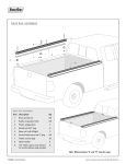
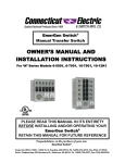
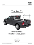
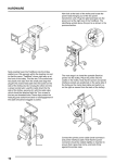
TOOLBOX MOUNT INSTALLATION
SKU# 25200
The ToolBox Mount Kit is designed to allow you to integrate your toolbox to the TracRac Base Rails:
Ø Mount your toolbox without drilling, bolting or damaging your truck.
Ø Slide your toolbox back to the tailgate for easy access.
Ø Painlessly remove your toolbox from the truck, for greater cargo carrying capacity.
Note: We design the TracRac system to accommodate most style toolboxes. Check to confirm that the belly of the
box fits between the baserails (on most trucks, the width of the belly needs to be 61” or less.)
Tools Required
1) Tape Measure
2) Power Drill
3) 1/8” Drill Bit
4) 1/2” Drill Bit
5) Socket Wrench
6) 9/16” Socket
7) 3/16” Allen Wrench
8) 1/4” Allen Wrench
9) Felt Tip Marker
Recommended
1) Torque Wrench
1) Verify that you have received the correct parts, using the attached Assembly Drawing and Packing Checklist.
2) Replace the knobs in the forward racks with the ½” x ½” Set Screws w/ Nylon Tip supplied with ToolBox
Mount assembly. (This allows the toolbox to fit directly behind the overhead racks!)
994 Jefferson Street, Fall River, MA 02721
Tel: 800-501-1587, 508-677-4130, Fax: 508-677-4136
(REV B) 06/11/02
Page 1 of 4
3) Your goal is to position the Mount Kit beneath your toolbox in the correct location, so the box can be mounted
to the Base Rails. Start by measuring the width between the Base Rail inner T-Tracks. (See Fig 1) Hook the
tape measure on the outer edge of the driver’s side inner T-Track and measure to the innermost edge of the
passenger side T-Track (this is Measurement A: mark it down below).
INNER TOP
T-TRACKS
PASSENGER’S SIDE
INNER EDGE
DRIVER’S SIDE
OUTER EDGE
A
BASERAILS
SIDE T-TRACK
Figure 1
4) Take your toolbox and measure the width of the box’s belly (Measurement B) (See Fig 2)
KNOB
LOCK NUT
FLAT WASHER
WING
D
DRILLING
LOCATION
BOX’S BELLY
B
Figure 2
5) Use the chart in Figure 2a to calculate where to drill the holes in your toolbox.
6) A minus B equals C & C divided by 2 equals D
Record Measurements Here
Measurement A:
minus
Measurement B:
Equals C:
Divide C by 2:
To get Measurement D:
Figure 2a
994 Jefferson Street, Fall River, MA 02721
Tel: 800-501-1587, 508-677-4130, Fax: 508-677-4136
(REV B) 06/11/02
Page 2 of 4
7) Flip the box upside down and mark off distance D from the edge of the box’s belly at the front and rear edge of
the toolbox wing. (Figure 3) Repeat for the opposite side. Connect the marks with a straight edge, and scribe a
line. This line is the drilling centerline.
8) You will be drilling the mounting holes on the centerlines from Step 6. Before drilling, double-check your
accuracy by measuring between centerlines. The distance should match Measurement A. (If not, repeat the
process to obtain A, B, and C.)
9) Before drilling the mounting holes, check the inside of your toolbox for the handle locations. If your toolbox’s
handles are on the sides, drill the knob access holes away from handles. The Toolbox Mounts are designed with
an alternate hole for the Knobs. This allows you to move the knob 4” off center to make room for the handles.
10) Drill a ½” diameter hole for the knob at the midpoint (or 4” from the midpoint) of the centerline on the toolbox
wing. Drill two ½” diameter holes along the same line, on each side of the center hole, approx. 6” from
midpoint of the centerline. Repeat for the other side. (Note: Use a 1/8” drill bit for an accurate pilot hole)
11) Slide the Slider Stops onto the inner Top T-Track, one on each side. Slide them to the front, cab-end of the
Base Rails.
D
SELF LOCKING NUTS
D
CENTERLINE
Figure 3
SLIDER STOPS
CAB - FRONT
T-BOLTS
PLASTIC SET SCREW
Figure 4
12) Slide the Toolbox Mounts onto the inner Top T-Track of each Base Rail, approximately 24”from tailgate.
Starting with the driver’s side, insert the Square Nut into the Slider’s Top Slot, and position it over the selected
hole for the Knob. (see step 8) Thread the 1” Plastic Set Screw through the Nut into the Slider. (Do not bottom
out screw into Base Rail.) Repeat on passenger side. (Figure 4)
994 Jefferson Street, Fall River, MA 02721
Tel: 800-501-1587, 508-677-4130, Fax: 508-677-4136
(REV B) 06/11/02
Page 3 of 4
13) Insert 2 T-Bolts into the slot on each slider, one from each end. Slide the T-Bolts so that each is 6” from the
plastic set screw.
Figure 5
14) Now mount the toolbox, making sure the Plastic Set Screws and T-Bolts protrude through the six holes in your
toolbox.
15) Remove Plastic Set Screws from assembly and immediately replace with the Knobs. Fasten the toolbox to the
sliders with the T-Bolts (in sliders), Flat Washers and Self Locking Nuts to the specified Torque of 240 in/lbs.
(20 ft/lbs.).
16) Now slide the toolbox the length of the Base Rails for final verification. Note: If the toolbox does not slide,
recheck that the Base Rails and Toolbox Mount Sliders are parallel, and that the toolbox is centered.
17) Slide the toolbox towards the cab, making sure you allow clearance to open the lid. Position the Slider Stops
under the toolbox until they butt up against the Toolbox Mounts. Pull the toolbox back and tighten the Set Screws
in the Slider Stops. (The Slider Stops will prevent the toolbox from sliding into the Overhead Racks.)
18) Slide the toolbox up until it butts against the Slider Stops and tighten the toolbox Knobs.
Note: The beds of some newer model trucks taper dramatically, impeding your ability to slide the toolbox entirely
off the tailgate. We recommend utilizing a toolbox with a narrow belly. Measure the width at your truck’s tailgate
to determine the maximum width of your truck bed.
CAUTION: Always make sure the knobs are tightened down to prevent the toolbox from sliding. Be sure to tighten
down the safety screws on the front and rear of the base rails as well.
994 Jefferson Street, Fall River, MA 02721
Tel: 800-501-1587, 508-677-4130, Fax: 508-677-4136
(REV B) 06/11/02
Page 4 of 4