1
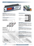
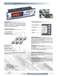
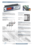
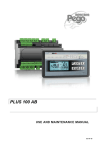
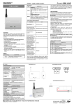
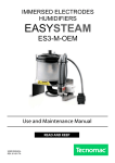
FAN-ASSISTED DISTRIBUTOR HEADS
USE AND MAINTENANCE MANUAL
Rel. 03 -06
Page 2
MANUALE D’USO – USER MANUAL
Thank you for choosing the PEGO EASYSTEAM fan-assisted distributor head.
Please read this manual thoroughly: doing so will allow you to carry out correct installation of the
unit and use it properly.
It is therefore advisable to store the manual near the fan-assisted distributor head installation point.
How to read this manual.
To simplify and aid comprehension the text is accompanied by the following symbols:
Indicates a section of text that must be read carefully.
Indicates tasks that need to be carried out with the utmost care and attention so as to
prevent damage to the distributor head, injury or malfunctions.
Indicates an action that is forbidden and which could cause damage to the distributor head,
injury or malfunctions.
Indicates a useful tip.
Indicates that the PEGO 2 HUMIDIFIER DIVISION assistance centre (contact details on
back of this handbook) should be contacted.
MANUALE D’USO – USER MANUAL
Page 3
CONTENTS
INTRODUCTION
Page
Page
Page
Page
Page
Page
Page
Page
5
5
5
6
6
6
7
7
1.1
1.2
1.3
1.4
1.5
1.6
1. 7
1.8
General
Warranty terms and conditions
Operating principle
Fan assisted head id codes
Technical data
Overal dimensions
Identification data
Items supplied as standard
INSTALLATION
Page 8
Page 9
Page 11
Page 11
2.1
2.2
2.3
2.4
General installation information
Standard installation
Remote installation
Electrical connection
SWITCHING
Page 12
3.1.
Initial start-up
TROUBLESHOOTING
Page 12
4.1
Troubleshooting
APPENDICES
Page 13
Page 14
Page 4
5.1
5.2
EC declaration of conformity
Exploden diagram
MANUALE D’USO – USER MANUAL
CHAP. 1
CHAP. 2
CHAP. 3
CHAP. 4
CHAP. 5
CHAP. 1 INTRODUCTION
1.1
GENERAL
The Pego Easysteam fan-assisted distributor head has been designed to allow direct humidification
of indoor environments without the need for air ducts or evaporators; ventilation can be achieved by
fitting the head directly on the humidifier or placing it in a ‘remote’, wall-mounted position.
1.2
1.2
WARRANTY TERMS AND CONDITIONS
Accessories of the EASYSTEAM product line are guaranteed against manufacturing defects for a
24-month period that begins on the date of delivery. Improper performance caused by tampering,
impact/knocks, improper installation or utilisation with equipment not belonging to the
EASYSTEAM line shall automatically render the warranty null and void. It is strongly
recommended that you observe all instructions/information regarding the technical characteristics of
the device.
Any modifications made to wiring and/or internal components or any tasks carried out in a
way that fails to comply with the information/instructions in this manual shall not only
render the warranty null and void immediately but may also lead to malfunctions,
irreparable damage, serious injury or put persons/objects in danger.
PEGO S.r.l. declines any responsibility for possible errors or inaccuracies written in this manual as
a result of printing or transcription errors.
PEGO S.r.l. reserves the right to modify its products as it deems necessary without altering their
main characteristics.
Each new release of a PEGO user manual replaces previous ones.
1.3
OPERATING PRINCIPLE
EASYSTEAM fan-assisted distributors mix the steam produced by the humidifiers with an airflow
generated by a cross-flow fan; this mixture is then introduced into the indoor environment at a
speed and rate proportional to the size of the humidifier, thus ensuring an optimal ratio of
humidification / efficiency loss caused by the condensation effect.
Ventilation occurs simultaneously with steam production; the shape of the head ensures that the
temperature of the outgoing air is less than 50°C and the grill pattern prevents direct introduction of
condensation water droplets into the environment.
MANUALE D’USO – USER MANUAL
Page 5
FAN-ASSISTED HEAD ID CODES
1.4
400UMFAN100
fan-assisted head for Pego easysteam humidifiers ES3-M, ES6
400UMFAN150
fan-assisted head for Pego easysteam humidifiers ES12, ES24
TECHNICAL DATA
1.5
TECHNICAL DATA
STEAM VENTILATION CAPACITY (in KG/h)
POWER SUPPLY
POWER (kW)
CONTROL TYPE
STEAM INLET DIAMETER (mm)
CONDENSATE DISCHARGE OUTLET DIAMETER (mm)
AIRFLOW RATE
400UMFAN150
Max 6
Max 24
220V 50 Hz
220V 50 Hz
0.20
0.28
EASYSTEAM
40
40
10
10
100 m3 /h
150 m3/ h
OVERALL DIMENSIONS
1.6
Page 6
400UMFAN100
MODEL
L
P
H
400UMFAN100
400UMFAN150
430 mm
430 mm
240 mm
240 mm
130 mm
130 mm
MANUALE D’USO – USER MANUAL
IDENTIFICATION DATA
1.7
The unit described in this manual has, on its side, an ID plate showing all the relevant identification
data:
• Name of Manufacturer
• Unit model
• Serial number
• Power
• Air capacity
1.8
ITEMS SUPPLIED AS STANDARD
EASYSTEAM fan-assisted distributor heads come complete, for purposes of assembly and use,
with:
N° 1 connector with an external diameter of 40 mm, for steam inlet
N° 1 connector with an external diameter of 10 mm, for condensate discharge
N° 1 head/humidifier connection hose
N° 1 humidifier cylinder connection flange
N° 1 condensation discharge pipe
N° 3 steam and condensate discharge connection seal clips
N° 1 user’s manual
N° 1 wall bracket (OPTIONAL)
MANUALE D’USO – USER MANUAL
Page 7
CHAP. 2 INSTALLATION
2.1
GENERAL INSTALLATION INFORMATION
1. Install the device as close as possible to the area where the steam is to be distributed (i.e. in a
position with as short a steam hose as possible). Do not exceed a distance of 5 metres.
2. Install the unit with Pego Easysteam humidifiers only.
3. Install the unit so it is level in both the transverse and longitudinal planes.
4. In the event of remote (wall-mounted) installation, make sure no water traps or kinks are created
on the steam inlet hose.
5. In the event of remote (wall-mounted) installation make sure the condensate recovery pipe is not
kinked.
6. When installing the device make sure the airflow is not directed at electronic equipment or other
equipment sensitive to high humidity.
Page 8
MANUALE D’USO – USER MANUAL
2.2
STANDARD INSTALLATION OF DISTRIBUTOR HEAD
1. Remove the fan-assisted distributor head from the packaging, keeping the device vertical.
Remove the protective nylon bag and check that the device is in good condition.
2. Replace the humidifier steam outlet flange (diameter 25 mm) with the supplied flange (Fig. 1)
(diameter 40 mm) (not necessary for ES24 humidifiers).
Fig. 1
3. Check that the humidifier is level both transversely and longitudinally; correct any tilt.
4. Connect the steam hose to the inlet (diameter 40 mm)(Fig.2) of the head and the condensate
discharge hose to the outlet (with diameter 10)(Fig.3).
Fig.2
Fig.3
MANUALE D’USO – USER MANUAL
Page 9
5. Fit the fan-assisted distributor head on the humidifier, positioning it on the upper part of the
latter; no screws are required, just press-lock it into place.(Fig. 4)
Fig. 4
6. Connect the steam hose to the humidifier flange.(Fig. 5)
Fig. 5
7. Make sure the condensate discharge hose is addressed to the humidifier outlet.
8. Pass the fan-assisted distributor head power lead through the Slim flat cable passage that
connects with the Master 100.
Page 10
MANUALE D’USO – USER MANUAL
2.3
REMOTE INSTALLATION OF DISTRIBUTOR HEAD
1. Remove the fan-assisted distributor head from the packaging, keeping the device vertical.
Remove the protective nylon bag and check that the device is in good condition.
2. Replace the humidifier steam outlet flange (diameter 25) with the supplied flange
(Fig.1)(diameter 40) (not necessary for ES24 humidifiers).
3. Fix the support bracket to the wall: make sure it is level both transversely and longitudinally
(Fig.6)
Fig. 6
4. Connect the steam hose to the inlet (diameter 40) (Fig.2) of the head and the condensate
discharge hose to the outlet (with diameter 10)(Fig.3)
5. Connect the steam hose to the humidifier flange.
6. Make sure the condensate discharge hose is directed towards the humidifier discharge or a
ground-level drainage point.
7. Pass the fan-assisted distributor head power lead through the Slim flat cable passage that
connects with the Master 100.
2.4
ELECTRICAL CONNECTION
Connect the lead to terminals 62 and 63 on the humidifier terminal block.
MANUALE D’USO – USER MANUAL
Page 11
CHAP. 3 SWITCHING
3.1
INITIAL START-UP
At this point the fan-assisted distributor head is ready for use and is fully autonomous.
When the humidifier receives consensus for steam production, the head starts to generate the
airflow with the requested quantity of steam.
CHAP. 4 TROUBLESHOOTING
4.1
TROUBLESHOOTING
FAULT
CAUSE
ACTION TO BE TAKEN
The humidifier generates steam
Check for proper connection and
but the head does not produce an
Cross-flow fan stopped
power supply
outflow
The humidifier generates steam
Cross-flow fan stopped despite
Check that cross-flow fan is
but the head does not produce an
proper power supply
working properly
outflow
The head sprays drops of
condensate outwards into the
Head not levelled properly
Check for level installation
room
The head sprays drops of
condensate outwards into the
Rear intake obstructed
Clean intake
room
Should you encounter any other faults not listed in the table please contact the PEGO 2
HUMIDIFIER DIVISION assistance centre
Page 12
MANUALE D’USO – USER MANUAL
CHAP. 5 APPENDICES
EC DECLARATION OF CONFORMITY
5.1
COSTRUTTORE / MANUFACTURER
PEGO SRL Via Piacentina,6b 45030 Occhiobello (RO) - ITALY DENOMINAZIONE DEL PRODOTTO / NAME OF THE PRODUCT
MOD.:
FAN ASSISTED DISTRIBUTOR HEAD SERIES ES 24.
IL PRODOTTO E’ CONFORME ALLE SEGUENTI DIRETTIVE CE/ THE PRODUCT
CONFORMS WITH THE REQUIREMENTS OF THE FOLLOWING EUROPEAN
DIRECTIVES:
2006/95/CE
Direttiva del Consiglio per l’unificazione delle normative dei Paesi CEE relativa al materiale
elettrico destinato ad essere utilizzato entro certi limiti di tensione e successive modificazioni
2006/95/EC
EC Directive on unification of laws of the Member States relating to electrical equipment employed
within certain voltage limits and subsequent amendments
89/336 CEE
Direttiva del Consiglio per l’unificazione delle normative dei Paesi CEE relativa alla
compatibilità elettromagnetica e successive modificazioni
89/336 EEC
EC Directive on unification of the laws of the Member States relating to electro-magnetic compatibility
and subsequent amendments
93/68 CEE
Direttiva del consiglio per la marcatura CE del materiale elettrico destinato ad essere utilizzato
entro taluni limiti di tensione.
LA CONFORMITA’ PRESCRITTA DALLE DIRETTIVE E’ GARANTITA DALL’
ADEMPIMENTO A TUTTI GLI EFFETTI DELLE SEGUENTI NORME:
CONFORMITY WITH THE REQUIREMENTS OF THESE DIRECTIVES IS TESTIFIED
BY COMPLETE ADHERENCE TO THE FOLLOWING STANDARDS:
NORME ARMONIZZATE / HARMONIZED EUROPEAN STANDARDS
EN 61000-6–1 EN 61000-6–3 EN 60335 – 1
MANUALE D’USO – USER MANUAL
Page 13
EXPLODED DIAGRAM
5.2
Ref.
12
3
4
5
6
7
Description
Cross-flow fan
Side heads in ABS
Stainless steel cover
Internal fixing partitions
Distributor lance
Condensate containment / collection tank
Separate installation support bracket (optional)
Page 14
MANUALE D’USO – USER MANUAL
NOTES
MANUALE D’USO – USER MANUAL
Page 15
PEGO 2 DIVISIONE UMIDIFICATORI / HUMIDIFIER DIV.
Via delle scienze, 28 45030 Occhiobello ROVIGO – ITALY
Tel. +39 0425 760349 Fax +39 0425 762905
e.mail: [email protected] – www.pego.it
PEGO s.r.l.
Via Piacentina, 6/b 45030 Occhiobello ROVIGO – ITALY
Tel. +39 0425 762906 Fax +39 0425 762905
e.mail: [email protected] – www.pego.it
CENTRO DI ASSISTENZA / ASSISTANCE CENTRE
Tel. +39 0425 760349 e.mail: [email protected]
Dealer:
Page 16
Doc. code: M.ES.05 rel. 01.07
PEGO s.r.l. reserves the right to modify this manual at any time.
MANUALE D’USO – USER MANUAL