1
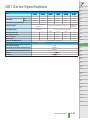
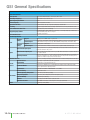
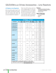
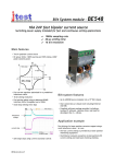
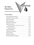
GS1 Series Introduction
GS1 Series Drives
Hp
kW
115 Volt Single Phase Input/230 Volt Three Phase Output
230 Volt Single Phase Input/230 Volt Three Phase Output
230 Volt Three Phase Input/Output
Motor Rating
Overview
The GS1 series of AC drives is our most
affordable and compact inverter, offering
V/Hz control with general purpose application features. These drives can be
configured using the built-in digital keypad
(which also allows you to set the drive
speed, start and stop, and monitor specific
parameters) or with the standard RS-485
serial communications port. Standard
GS1 features include one analog input,
four programmable digital inputs and one
programmable normally open relay
output.
Features
.25
0.2
.5
0.4
1
0.75
✔
✔
✔
✔
✔
2
1.5
✔
Accessories
• Simple Volts/Hertz control
• Pulse Width Modulation (PWM)
• 3 - 10 kHz carrier frequency
• IGBT technology
• 130% starting torque at 5Hz
• 150% rated current for one minute
• Electronic overload protection
• Stall prevention
• Adjustable accel and decel ramps
• S-curve settings for acceleration and
deceleration
• Automatic torque compensation
• Automatic slip compensation
• DC braking
• Built-in EMI filter
• Three skip frequencies
• Trip history
• Integral keypad and speed potentiometer
• Programmable jog speed
• Three programmable preset speeds
• Four programmable digital inputs
• One programmable analog input
• One programmable relay output
• RS-485 Modbus communications up to
19.2K
• Optional Ethernet communications
• UL/CE listed
• AC line reactors
• RF filter
• Ethernet interface
• Four and eight port RS-485 multi-drop
termination board
• KEPDirect I/O Server
• GSoft drive configuration software
Detailed descriptions and specifications for the
accessories are available in the “GS/DURAPULSE
Accessories” section.
Typical Applications
• Conveyors
• Fans
• Pumps
• Shop tools
GS1 series part numbering system
GS1 - 2 0P5
Applicable Motor Capacity
0P2: 1/4hp
1P0: 1hp
0P5: 1/2hp
2P0: 2hp
Input Voltage
1: 100-120VAC
2: 200-240VAC
Series Name
12–14
Drives/Motors/Motion
01737-824600
GS1 Series Specifications
PLC
Overview
DL05/06
PLC
115V/230V CLASS GS1 Series
Model
Motor Rating
GS1-10P2
HP
kW
Rated Output Capacity (200V) kVA
Rated Input Voltage
Rated Output Voltage
Rated Input Current (A)
Rated Output Current (A)
Watt Loss 100% (I)
Weight: kg (lb)
Dimensions (HxWxD) mm (in)
GS1-10P5
GS1-20P2
GS1-20P5
GS1-21P0
GS1-22P0
DL105
PLC
DL205
PLC
1/4 hp
1/2 hp
1/4 hp
1/2 hp
1hp
2hp
0.2 kW
0.4 kW
0.2 kW
0.4 kW
0.7 kW
1.5 kW
0.6
1.0
0.6
1.0
1.6
2.7
Single phase 100-120 VAC 10%,
50/60 Hz 5%
Three phase: 200240 VAC±10%,
50/60 Hz ±5%
Single/three phase: 200-240 VAC±10%, 50/60 Hz ±5%
Three phase corresponds to double the
input voltage
Three phase corresponds to the input voltage
DL405
PLC
Field I/O
6
9
4.9/1.9
6.5/2.7
9.7/5.1
9
1.6
2.5
1.6
2.5
4.2
7.0
19.2
19.2
18.4
26.8
44.6
73
2.10
2.20
2.20
2.20
2.20
2.20
Software
C-more
HMIs
Other HMI
132.0 x 68.0 x128.1 (5.20 x 2.68 x 5.04)
Accessories
Ethernet Communications module for GS Series
Drives (DIN rail mounted)
Four port RS-485 multi-drop termination board
Eight port RS-485 multi-drop termination board
Software
OPC Server
DL305
PLC
AC Drives
GS-EDRV
Motors
GS-RS485-4
GS-RS485-8
Steppers/
Servos
GSoft / KEPDirect
KEPDirect
Motor
Controls
Proximity
Sensors
Photo
Sensors
Limit
Switches
Encoders
Pushbuttons/
Lights
Process
Relays/
Timers
Comm.
TB’s &
Wiring
Power
Enclosures
Appendix
Part Index
Drives/Motors/Motion
12–15
GS1 General Specifications
General Specifications
Control Characteristics
Control System
Rated Output Frequency
Output Frequency Resolution
Overload Capacity
Torque Characteristics
DC Braking
Acceleration/Deceleration Time
Sinusoidal Pulse Width Modulation, carrier frequency 3kHz - 10kHz
Voltage/Frequency Pattern
V/F pattern adjustable. Settings available for Constant Torque - low and high starting torque, Variable Torque low and high starting torque, and user configured
Stall Prevention Level
20 to 200% or rated current
1.0 to 400.0 Hz limited to 9999 motor rpm
0.1 Hz
150% of rated current for 1 minute
Includes auto-torque, auto-slip compensation, starting torque 130% @ 5.0Hz
Operation frequency 60-0Hz, 0-30% rated voltage. Start time 0.0-5.0 seconds. Stop time 0.0-25.0 seconds
0.1 to 600 seconds (can be set individually)
Operation Specification
Frequency
Setting
Inputs
Operation
Setting
Outputs
Keypad
Setting by <UP> or <DOWN> buttons or potentiometer
External Signal
Potentiometer - 5k 0.5W, 0 to 10 VDC (input impedance 47k), 0 to 20 mA / 4 to 20 mA (input impedance
250), Multi-function inputs 1 to 3 (3 steps, JOG, UP/DOWN command), RS485 communication setting
Keypad
External Signal
Setting by <RUN>, <STOP> buttons
Multi-Function Input Signal
Multi-step selection 0 to 3, Jog, Accel/decel inhibit, First/second accel/decel switch, Counter, PLC operation,
External base block (N.C., N.O.) selection
Multi-Function Output Signal
AC drive operating, Frequency attained, Non zero speed, Base Block, Fault indication, Local/remote indication,
PLC operation indication
Operating Functions
Automatic voltage regulation, S-curve, Over-voltage stall prevention, DC braking, Fault records, Adjustable carried frequency, Starting frequency setting of DC braking, Over-current stall prevention, Momentary power loss
restart, Reverse inhibition, Frequency limits, Parameter lock/reset
Protective Functions
Operator Devices
Programming
Operator
Interface
Parameter Monitor
Environment
Key Functions
Enclosure Rating
Ambient Operating Temperature
Storage Temperature
Ambient Humidity
Vibration
Installation Location
Options
12–16
DI1, DI2, DI3, DI4 can be combined to offer various modes of operation, RS485 communication port
Drives/Motors/Motion
Overcurrent, overvoltage, undervoltage, electronic thermal motor overload, Overheating, Overload, Self testing
5-key, 4-digit, 7-segment LED, 3 status LEDs, potentiometer
Parameter values for setup and review, fault codes
Master Frequency, Output Frequency, Scaled Output Frequency, Output Voltage, DC Bus Voltage, Output
Direction, Trip Event Monitor, Trip History Monitor
RUN/STOP, DISPLAY/RESET, PROGRAM/ENTER, <UP>, <DOWN>
Protected chassis, IP20
-10° to 40°C (14°F to 104°F) w/o derating
-20° to 60 °C (-4°F to 140°F) during short-term transportation period)
0 to 90% RH (non-condensing)
9.8 m/s2(1G), less than 10Hz. 5.88 m/s2 (0.6G) 20 to 50 Hz
Altitude 1000m or lower above sea level, keep from corrosive gas, liquid and dust
Programming Software (GSOFT)
01737-824600
GS1 Specifications - Installation
PLC
Overview
Understanding the installation requirements
for your GS1 drive will help to ensure that it
will operate within its environmental and electrical limits.
DL05/06
PLC
NOTE:
Never use only this catalog for installation instructions or
operation of equipment; refer to the user manual, GS1-M.
DL205
PLC
DL105
PLC
DL305
PLC
Environmental Specifications
Protective Structure
Ambient Operating
Temperature 2
Storage
Temperature 3
IP20
Humidity
to 90%
(no condensation)
Vibration 4
5.9 m/S2 (0.6G),
10 to 55 Hz
Location
DL405
PLC
Fan
Field I/O
6"
150mm
min
-10 to 40°C
-20 to 60°C
Software
2"
50mm
min
C-more
HMIs
Other HMI
2"
50mm
min
Altitude 1,000 m or less,
indoors (no corrosive
gases or dust)
AC Drives
Motors
1: Protective structure is based upon EN60529
2: The ambient temperature must be in the range of
-10° to 40° C. If the range will be up to 50° C, you
will need to set the carrier frequency to 2.1 kHz or
less and derate the output current to 80% or less.
See our Web site for derating curves.
Steppers/
Servos
6"
150mm
min
Motor
Controls
3: The storage temperature refers to the short-term
temperature during transport.
Proximity
Sensors
4: Conforms to the test method specified in JIS CO911
(1984)
Photo
Sensors
Panel
Watt-loss Chart
GS1 Drive Model
At full load
GS1-10P2
GS1-10P5
GS1-20P2
GS1-20P5
GS1-21P0
GS1-22P0
19.2
Ground braid
copper lugs
Input
Power
Limit
Switches
To
Motor
Encoders
* FOR PAINTED SUB-PANELS,
19.2
SCRAPE THE PAINT FROM UNDER-
18.4
NEATH THE STAR WASHERS
26.8
Star washers*
Panel or single
point ground*
BEFORE TIGHTENING THEM.
44.6
Pushbuttons/
Lights
Process
Relays/
Timers
73
Air Flow
Warning: AC drives generate a large
amount of heat, which may damage the
AC drive. Auxiliary cooling methods
are typically required in order to not
exceed maximum ambient
temperatures.
Comm.
TB’s &
Wiring
Power
Enclosures
Appendix
Part Index
Drives/Motors/Motion
12–17
GS1 Specifications - Terminals
Main Circuit Wiring
Terminal
Description
L1, L2, L3
T1, T2, T3
Input power
AC drive output
Ground
Control Circuit Terminals
1
Terminal Symbol
Description
R1O
R1
DI1
DI2
DI3
DI4
AI 1
+10V
CM
Relay output 1 normally open
Relay output 1 common
Digital input 1
Digital input 2
Digital input 3
Digital input 4
Analog input
Internal power supply (10 mA @ 10 VDC)
Common
0 to +10 VDC, 0 to 20 mA, or 4 to 20 mA input represents zero to maximum output frequency.
Note: Use twisted-shielded, twisted-pair or shielded-lead wires for the control signal wiring. It is recommended
all signal wiring be run in a separate steel conduit. The shield wire should only be connected at the drive.
Do not connect shield wire on both ends.
12–18
Drives/Motors/Motion
01737-824600
GS1 Specifications - Basic Wiring Diagram
Note: Users MUST connect wiring according to the circuit diagram shown below. (Refer to user manual GS1-M for additional specific wiring information.)
DL205
PLC
Power Source 3 phase*
AC Motor
L1
L2
GS1-xxxx
T1
IM
T2
L3
C-more
HMIs
Other HMI
Grounding resistance
less than 0.1
External Fault (N.0)
DI1
R1O
Multi-function output contacts
120VAC/24VDC @5A
230VAC @2.5A
R1
Fault Indication
RJ-12 (6P4C)
RJ-12 Serial Comm Port
DI3
6
1
Jog
CM
AC Drives
Motors
Steppers/
Servos
Motor
Controls
DI2
DI4
Common Signal
DL405
PLC
Software
* Use terminals L1 and L2 for 120V, or
select any two of the power terminals
for 240V single phase models
Reverse/Stop
DL305
PLC
Field I/O
T3
Forward/Stop
DL05/06
PLC
DL105
PLC
Note: Refer to the following pages for explanations and information regarding line reactors and RF filters: 12–50, 12–67.
100-120V±10%
(50/60Hz ±5%)
200-240V±10%
(50/60Hz±5%)
PLC
Overview
Communication Port
Proximity
Sensors
Photo
Sensors
RS-485
2: GND
3: SG4: SG+
5: +5V
Limit
Switches
Encoders
Pushbuttons/
Lights
Process
Analog voltage
0-10VDC
Potentiometer
3~5k
Analog current
0-20mA; 4-20mA
+10V 10mA
(max)
AI
Relays/
Timers
Comm.
TB’s &
Wiring
CM
Power
Enclosures
Factory default setting
Appendix
Factory default source of frequency command is via the keypad potentiometer
Main circuit (power) terminals
Control circuit terminal
Shielded leads
WARNING: Do not plug a modem or telephone into the GS1 RJ-12 Serial Comm Port, or permanent damage may result.
Terminals 2 and 5 should not be used as a power source for your communication connection.
Drives/Motors/Motion
12–19
Part Index
GS1 Specifications - Dimensions
68.0 (2.68)
)
20
56.0 (2.20)
.
.5
dia
0.
0(
STOP
RUN
FWD
REV
0
PROG
ENTER
100
132.0 (5.20)
RUN
STOP
120.0 (4.72)
DISPL
RESET
V
I
R1 R1O+ 10V AI DI1 DI2 DI3 DI4 CM
12–20
Drives/Motors/Motion
128.1 (5.04)
123.4 (4.86)
128.1 (5.04)
Unit: mm (in)
01737-824600
GS/DURAPULSE Accessories – Overview
Accessories
part numbering system
GS - 23P0 - LR - 3PH
Description Code (optional)
1PH: Single phase 3PH: Three phase ENC: Enclosure
Blank: For reactor, check specific part # to determine phase
Accessory Code
BR: Braking resistor FKIT: Fuse Kit
FUSE: Replacement fuses for FKIT LR: Line reactor
Note: With the exception of the EMI filters and RF filters, each accessory
part number begins with GS, followed by the AC Drive rating, and then
the relevant accessory code. Following the accessory code, you will find
a description code when applicable. The diagram at right shows the
accessory part numbering system.
Drive Rating (See Drive P/N description)
BZL: Bezel CBL: Cable DBU: Dynamic Brake Unit
EDRV: Ethernet board FB: Feedback board
KPD: Keypad RS: Recommended Standard
Drive Series
GS: All GS and DURApulse Series Drives
GS1: GS1 Series GS2: GS2 Series
GS3: DURApulse Series
Under 20hp
Power Supply
Please follow the specific power supply requirements shown in Chapter 1 and the
Warning section of the applicable GS or DURAPULSE AC Drives User Manual.
From power supply
1
(Refer to page 12–68.)
Input fuses protect the AC drive from excessive input current due to line surges, short
circuits, and ground faults. They are recommended for all installations and may be
required for UL-listed installations. (AutomationDirect fuses are not available for GS1
drives.)
Disconnect switch
2
3
Fuses
Contactor (Optional)
(Refer to the Motor Controls section.)
Do not use a contactor or disconnect switch for run/stop control of the AC drive and
motor. This will reduce the operating life cycle of the AC drive. Cycling a power circuit
switching device while the AC drive is in run mode should be done only in emergency
situations.
4
6
5
L1
L2
+
(–)
T2
7
RF filter (Optional)
(Refer to page 12–67.)
Braking Resistor (Optional)
(Refer to page 12–56.)
Dynamic braking allows the AC drive to produce additional braking (stopping) torque.
AC drives can typically produce between 15% & 20% braking torque without the addition of any external components. The addition of optional braking may be required for
applications that require rapid deceleration or high inertia loads. (Braking resistors are
not available for GS1 drives.)
8
Motor
Motor grounding
terminal
12–46
(Refer to page 12–61.)
RF filters reduce the radio frequency interference or noise on the input or output side of
the inverter.
T3
6
EMI filter (Optional)
Input EMI filters reduce electromagnetic interference or noise on the input side of the AC
drive. They are required for CE compliance and recommended for installations prone
to or sensitive to electromagnetic interference. (Separate EMI filters are not neccessary
for GS1 drives.)
B1
B2
T1
(Refer to page 12–50.)
Input line reactors protect the AC drive from transient overvoltage conditions, typically
caused by utility capacitor switching. The input line reactor also reduces the harmonics
associated with AC drives. Input line reactors are recommended for all installations.
L3
GS and
DURAPULSE
AC Drive
GSx-xxxx
Input Line Reactor (Optional)
Drives/Motors/Motion
Output Line Reactor (Optional)
(Refer to page 12–50.)
Output line reactors protect the motor insulation against AC drive short circuits and
IGBT reflective wave damage, and also “smooth” the motor current waveform, allowing
duty”
the motor to run cooler. They are recommended for operating “non-iinverter-d
motors and when the length of wiring between the AC drive and motor exceeds 75 feet.
01737-824600
GS/DURAPULSE Drives Accessories – Line Reactors
115 Volt Single Phase Input Reactors
NOTE: Single phase line reactors should not be installed on the output of the AC Drive.
Part Number
Rated Impedance Inductance Watt
Amps
Loss
Drive Model and Side
/ Phase / Volts
Drive
hp
GS-10P2-LR
18
3%
0.80 mH
19
GS1-10P2 (input) / 1ph / 115V
GS2-10P2 (input) / 1ph / 115V
0.25
GS-10P5-LR
25
3%
0.50 mH
23
GS1-10P5 (input) / 1ph / 115V
GS2-10P5 (input) / 1ph / 115V
0.5
GS-11P0-LR
35
3%
0.40 mH
36
GS2-11P0 (input) / 1ph / 115V
1
230 Volt Single Phase Input Reactors
NOTE: Single phase line reactors should not be installed on the output of the AC Drive.
Part Number
Rated Impedance Inductance Watt
Amps
Loss
Drive Model and Side
/ Phase / Volts
Drive
hp
GS-20P5-LR-1PH
8
3%
6.50 mH
13
GS1-20P5 (input) / 1ph / 230V
GS2-20P5 (input) / 1ph / 230V
0.5
GS-21P0-LR-1PH
12
3%
6.50 mH
13
GS1-21P0 (input) / 1ph / 230V
GS2-21P0 (input) / 1ph / 230V
1
GS-22P0-LR-1PH
GS-23P0-LR-1PH
18
3%
3.00 mH
25
GS2-22P0 (input) / 1ph / 230V
2
35
3%
2.50 mH
26
GS2-23P0 (input) / 1ph / 230V
3
230 Volt Three Phase Input / Output Reactors
Part Number
12–50
Rated Impedance Inductance Watt
Amps
Loss
Drive Model and Side
/ Phase / Volts
Drive
hp
GS-20P5-LR-3PH
4
3%
6.50 mH
13
GS1-10P5 (output) / 3ph / 230V
GS1-20P5 (in/out) / 3ph / 230V
GS2-20P5 (in/out) / 3ph / 230V
0.5
GS-21P0-LR-3PH
4
3%
3.00 mH
7
GS1-21P0 (in/out) / 3ph / 230V
GS2-21P0 (in/out) / 3ph / 230V
GS3-21P0 (in/out) / 3ph / 230V
1
GS-22P0-LR-3PH
8
3%
1.50mH
11
GS1-22P0 (in/out) / 3ph / 230V
GS2-22P0 (in/out) / 3ph / 230V
GS3-22P0 (in/out) / 3ph / 230V
2
GS-23P0-LR-3PH
12
3%
1.30mH
23
GS2-23P0 (in/out) / 3ph / 230V
GS3-23P0 (in/out) / 3ph / 230V
3
GS-25P0-LR
18
3%
0.80mH
19
GS2-25P0 (in/out) / 3ph / 230V
GS3-25P0 (in/out) / 3ph / 230V
5
GS-27P5-LR
25
3%
0.50mH
23
GS2-27P5 (in/out) / 3ph / 230V
GS3-27P5 (in/out) / 3ph / 230V
7.5
GS-2010-LR
GS-2015-LR
GS-2020-LR
GS-2025-LR
GS-2030-LR
GS-2040-LR
GS-2050-LR
35
3%
0.40mH
36
GS3-2010 (in/out) / 3ph / 230V
10
45
3%
0.30mH
33
GS3-2015 (in/out) / 3ph / 230V
15
55
3%
0.25mH
39
GS3-2020 (in/out) / 3ph / 230V
20
80
3%
0.20mH
88
GS3-2025 (in/out) / 3ph / 230V
25
80
3%
0.20mH
88
GS3-2030 (in/out) / 3ph / 230V
30
130
3%
0.10mH
95
GS3-2040 (in/out) / 3ph / 230V
40
130
3%
0.10mH
95
GS3-2050 (in/out) / 3ph / 230V
50
Drives/Motors/Motion
01737-824600
GS/DURAPULSE Drives Accessories – Line Reactors
AC Line Reactor Dimensions (inches)
Part Number
GS-10P2-LR
GS-10P5-LR
GS-11P0-LR
GS-20P5-LR-1PH
GS-20P5-LR-3PH
GS-21P0-LR-1PH
GS-21P0-LR-3PH
GS-22P0-LR-1PH
GS-22P0-LR-3PH
GS-23P0-LR-1PH
GS-23P0-LR-3PH
GS-25P0-LR
GS-27P5-LR
GS-2010-LR
GS-2015-LR
GS-2020-LR
GS-2025-LR
GS-2030-LR
GS-2040-LR
GS-2050-LR
GS-41P0-LR
GS-42P0-LR
GS-43P0-LR
GS-45P0-LR
GS-47P5-LR
GS-4010-LR
GS-4015-LR
GS-4020-LR
GS-4025-LR
GS-4030-LR
GS-4040-LR
GS-4050-LR
GS-4060-LR
GS-4075-LR
GS-4100-LR
GS-51P0-LR
GS-52P0-LR
H
W
D
Mtg D
Mtg W
Mtg Slot Hole Size
Weight (lbs)
4.80
6.00
3.30
2.09
2.00
0.28 x 0.63
7.10
5.7
6.00
3.09
2.09
3.00
0.28 x 0.63
7.00
5.7
6.00
3.34
2.34
3.00
0.28 x 0.63
8.90
3.40
4.40
2.83
1.77
1.44
0.28 x 0.63
2.80
3.40
4.40
2.83
1.77
1.44
0.28 x 0.63
2.80
3.40
4.40
2.83
1.77
1.44
0.28 x 0.63
2.80
3.40
4.40
2.83
1.77
1.44
0.28 x 0.63
2.30
3.40
4.40
2.83
1.77
2.00
0.28 x 0.63
3.10
3.40
4.40
2.83
1.77
2.00
0.28 x 0.63
2.80
4.80
6.00
3.30
2.09
2.00
0.28 x 0.63
7.50
3.40
4.40
2.83
1.77
2.00
0.28 x 0.63
2.90
4.80
6.00
3.30
2.09
2.00
0.28 x 0.63
7.10
5.70
6.00
3.09
2.09
3.00
0.28 x 0.63
7.00
5.70
6.00
3.34
2.34
3.00
0.28 x 0.63
9.00
5.70
6.00
3.84
2.84
3.00
0.28 x 0.63
13.0
5.70
6.00
3.84
2.84
3.00
0.28 x 0.63
12.0
6.88
8.50
4.37
3.12
3.60
0.44 x 1.00
26.0
6.88
8.50
4.37
3.12
3.60
0.44 x 1.00
26.0
6.88
8.50
4.37
3.12
3.00
0.44 x 1.00
27.0
6.88
8.50
4.37
3.12
3.00
0.44 x 1.00
27.0
3.40
4.40
2.83
1.77
1.44
0.28 x 0.63
2.30
3.40
4.40
2.83
1.77
1.44
0.28 x 0.63
2.80
3.40
4.40
3.39
2.39
2.00
0.28 x 0.63
4.30
3.40
4.40
2.83
1.77
2.00
0.28 x 0.63
3.10
4.80
6.00
3.30
2.09
2.00
0.28 x 0.63
7.50
4.80
6.30
3.55
2.34
2.00
0.28 x 0.63
9.10
5.70
6.00
3.34
2.34
3.00
0.28 x 0.63
10.0
5.61
6.90
3.95
2.75
3.00
0.38 x 0.63
17.0
5.61
6.90
3.95
2.75
3.00
0.38 x 0.63
17.0
5.61
6.90
4.45
3.25
3.00
0.38 x 0.63
22.0
6.88
8.50
4.37
3.12
3.00
0.44 x 1.00
26.0
6.88
8.50
4.87
3.62
3.60
0.44 x 1.00
36.0
6.88
8.50
4.87
3.62
3.60
0.44 x 1.00
36.0
8.29
10.50
5.35
3.73
3.60
0.44 x 1.25
52.0
8.29
10.50
5.35
3.73
3.60
0.44 x 1.25
41.0
3.40
4.40
2.83
1.77
1.44
0.28 x 0.63
3
3.40
4.40
2.83
1.77
1.44
0.28 x 0.63
3
Mounting holes
W
MTG
w
H
x
12–52
Label
Drives/Motors/Motion
MTG
D
D
01737-824600
GS/DURAPULSE Drives Accessories – Line Reactors
PLC
Overview
Input side of the drive
DL05/06
PLC
When installed on the input side of the AC drive, line
reactors will reduce line notching, and limit current and
voltage spikes and surges from the incoming line. The
line reactor will also reduce harmonic distortion from the
drive onto the line. Units are installed in front of the AC
drive as shown.
C2
C1
L3
DL105
PLC
T3
B2
B1
T2
L2
DL205
PLC
T1
A2
A1
L1
DL305
PLC
DL405
PLC
Output side of the drive
T3
C1
C2
T2
B1
B2
T1
A1
A2
Field I/O
When installed on the output side of the drive, line reactors
protect the drive from short circuits at the load. Voltage and
current waveforms from the drive are enhanced, reducing motor
overheating and noise emissions.
Note: Single phase line reactors should not be installed on the output of the AC
Drive. Use three-phase only.
Software
C-more
HMIs
Other HMI
AC Drives
Multiple drives
Motors
Individual line reactors are recommended when
installing multiple drives on the same power line.
Individual line reactors eliminate cross talk between
multiple drives and provide isolated protection for
each drive for its own specific load.
C1
C2
L3
B1
B2
L2
A1
A2
L1
T3
Steppers/
Servos
T2
T1
Motor
Controls
Proximity
Sensors
Photo
Sensors
C1
C2
L3
B1
B2
L2
A1
A2
L1
Limit
Switches
T3
T2
Encoders
T1
Pushbuttons/
Lights
Process
Multiple motors
T3
C1
C2
T2
B1
B2
A single reactor can be used when the application calls for multiple
motors on the same drive. The reactor is sized based upon the total
horsepower of all the motors. Overload relays (not shown) are recommended for use in multi-motor applications.
A2
Note: A single reactor should only be used with multiple motors when the motors will
always operate simultaneously.
T1
A1
TB’s &
Wiring
Enclosures
C1
C2
B1
B2
A1
A2
L2
Appendix
T3
T2
T1
Part Index
L1
WARNING: Please ensure that terminals B1 and B2 are properly
insulated before making any connections to single-phase power.
Drives/Motors/Motion
Comm.
Power
Single phase applications
Some of the line reactors are listed for use with single-phase input
power. Follow the connection diagram to the left. Make sure that
terminals B1 and B2 are properly insulated before any connections are
made.
Relays/
Timers
12–53
GS/DURAPULSE Accessories – RF Filter
PLC
Overview
DL05/06
PLC
RF Filter for GS/DURAPULSE AC Drives
Part Number
Drive Model
RF220X00A
GSx-xxxx
DL105
PLC
DL205
PLC
Can be used with all series GS/DURAPULSE AC drives
DL305
PLC
Description
DL405
PLC
Zero phase reactors, (aka RF noise filters)
help reduce radiated noise from the
inverter wiring. The wiring must go
through the opening to reduce the RF
component of the electrical noise. Loop
the wires three times (four turns) to attain
the full RF filtering effect. For larger wire
sizes, place multiple zero-phase reactors
(up to four) side by side for a greater
filtering effect. These are effective for
noise reduction on both the input and
output sides of the inverter. Attenuation
quality is good in a wide range from AM
band to 10 Mhz.
Field I/O
Software
C-more
HMIs
Other HMI
Wiring Method
Wind each wire four times around the
core, as shown in diagram A to the right.
The reactor must be put at inverter side
as closely as possible.
Motors
36 (1.42)
35 (1.38)
68.5 (2.70)
AC Drives
90 (3.54)
Steppers/
Servos
25 (0.98)
Motor
Controls
80 (3.15)
Proximity
Sensors
UNITS:
mm (in)
If you are unable to wire as above due to
wire size or another aspect of your application, put all wires through four cores in
series without winding, as in diagram B
to the right.
Photo
Sensors
TOP VIEW
Limit
Switches
Encoders
A
Pushbuttons/
Lights
Line
L1
T1
L2
T2
L3
T3
Power
Process
MOTOR
Relays/
Timers
Comm.
TB’s &
Wiring
B
Line
Power
Power
L1
L2
L3
T1
T2
T3
Enclosures
MOTOR
Appendix
Part Index
Drives/Motors/Motion
12–67
GS/DURAPULSE Accessories – Ethernet Interface
Overview
The GS-EDRV Ethernet interface provides a
high-performance Ethernet link between a
control system and any GS or DURAPULSE
AC drive. The GS-EDRV processes signals
to and from the drive, mounts on a DIN
rail, and connects the drive to an Ethernet
hub or PC. It formats signals to conform
with the Ethernet standard to the H2-ERM
or H4-ERM, KEPDirect EBC I/O server (as
shown on the following page), or independent controller with a Modbus TCP/IP
driver. This allows for greater connectivity
to many control system architectures.
An additional feature is the built-in web
browser which allows users to configure
and control the drive from any web
browser via the IP address of the
GS-EDRV card.
D2-260 with
H2-ERM
GS-EDRV works
with GS1, GS2, and
GS3/DURAPULSE
drives.
GS-EDRV
GS-EDRV
E-SW05U
PLC
Overview
DL05/06
PLC
DL105
PLC
DL205
PLC
DL305
PLC
DL405
PLC
Field I/O
Software
C-more
HMIs
DURAPULSE Drive
DURAPULSE Drive
Other HMI
AC Drives
Note: The GS-EDRV requires an external 24 VDC
power supply.
Communication Ports
Dip Switches
Motors
Automatic power
shut-down
Steppers/
Servos
The GS series drives have a provision for
shutting down control or power to the
inverter in the event of a communications
time-out. This function can be set up
through the drive parameter group 9.
Proximity
Sensors
Motor
Controls
Photo
Sensors
Limit
Switches
Encoders
Specifications
Part Number
GS-EDRV
Input Voltage
Input Current
10-33 VDC
Pushbuttons/
Lights
Process
LED Indicators
90-135 mA
Can be used with all series GS/DURAPULSE AC drives
Relays/
Timers
Power Terminals
Chassis or system ground connection
Negative connection (-) or 0VDC
Positive connection (+) or +24 VDC
Comm.
TB’s &
Wiring
Power
Dimensions
Enclosures
Appendix
2.7"
Part Index
1.9"
4.0"
units: inches
Drives/Motors/Motion
12–71
GS/DURAPULSE Accessories – Software
KEPDirect I/O Server
Overview
The KEPDirect EBC I/O server software is a
32-bit application that provides a way to
connect your favorite Windows client software to AUTOMATIONDIRECT Ethernet I/O
through our Ethernet base controllers. It
provides GS/DURAPULSE series drive
support via the GS-EDRV Ethernet interface, as shown in the diagram below.
KEPDirect allows the user a direct line into
the drive parameter group just like an
Ethernet field I/O drop. The user can
control or monitor from any OPC/DDE
compliant third party software. For a
complete description of KEPDirect software
features, go to the Software section of this
catalog. Several application notes specific
to the versatility of this software can be
found on our web site at www.automationdirect.com.
KEPDirect I/O Server Software
Part Number
Description
PC-KEPEBC-3
Supports up to three
GS-EDRV or EBC
nodes
PC-KEPEBC-7
Supports up to
seven GS-EDRV or
EBC nodes
PC-KEPEBC-8P
Supports eight or
more GS-EDRV or
EBC nodes
CMMS and Condition
Monitoring of Drives and
Hardware Applications
Condition monitoring is usually the last
part of CMMS (Computer Maintenance
Management Software) implementation to
be explored. It is expensive and difficult to
use. Traditionally, the CMMS companies
have used custom built data acquisition
(DAQ) boards to monitor systems for
values like vibration or temperature.
New technologies like KEPDirect,
GS/DURAPULSE drives, and Terminator
field I/O are perfect matches to allow the
user to dispose of expensive proprietary
DAQ boards. In addition to the cost
savings, the intuitive set-up will reduce
implementation.
These will become the standard tools that
monitor control loop performance on-line
and in real time. These tools enable
continuous monitoring of control loops,
and instant notification of operational
deviations as they occur. Using OPC to tie
these systems into CMMS provides
tracking and automatic evaluation of your
soft and hard assets. It also enables easy
tracking of true operational and maintenance costs associated with those assets.
Personnel can focus on fixing the cause of
the problem, and not just the symptom.
to next
PC-KEPEBC-UPG Upgrade
larger package
Can be used with all series GS/DURAPULSE AC drives;
Requires GS-EDRV Ethernet interface.
KEPDirect I/O
Server Software
Larger Scale Asset Management
Applications
On a larger scale, such as Asset
Management Software, there is too much
information to directly link to the software
(many of them are OPC/DDE compliant).
There must be a buffer of some type.
Usually this buffer is a SCADA type
package that handles distribution of information gathered by condition monitoring
field devices. KEPDirect and Terminator
field I/O can connect as easily to the
SCADA software as to any OPC compliant
software.
Major OPC Clients
supported
• Rockwell Software RSView32®
• GE’s Cimplicity®
• Iconics’ Genesis32®
• Cutler Hammer’s PanelMate PC Pro
• Think & Do Live!
• Think & Do Studio
• Wonderware’s In Touch® and OPCLink®
• Intellution’s Fix Dynamics® and OPC
Power Tool®
• Siemen’s WinCC®
• Kepware’s OPC QuickClient
• BizWareDirect’s DataNet OPC
System Requirements
To run KEPDirect I/O Server, your PC must
meet the following requirements:
• Pentium CPU, 400 Mhz clock speed
• Windows 98, NT 4.0 SP5, 2000 or XP
• 64 MB free RAM and 10 MB free hard disk
space
GS-EDRV
E-SW05U
GS1, GS2, GS3/
DURAPULSE
Drives
12–72
Drives/Motors/Motion
01737-824600
GS/DURAPULSE Accessories – Software
System Requirements
To run GSoft, your PC must meet the
following requirements:
• Windows 95, 98, Me, NT, 2000 or XP
• Internet Explorer 4.0 or higher
(for HTML help support)
• 24 Mb of available memory
• 8Mb hard drive space
• Available RS-232 serial port
Overview
GSoft, the configuration software for the
GS/DURAPULSE drives, allows a personal
computer to be directly connected to the
drives via RS-232 or RS-485 (RS-485
requires FA-ISOCON or user supplied
converter). You can perform a variety of
functions to allow easy, intuitive, and
secure set-up of any application that is
required using GSoft.
Features
• Create new drive configurations using one
of three views:
• Quick Start - Allows for just the basic
set-up to get quick and simple applications up and running ASAP.
• Detailed - The complete set-up of all
parameters in the drive.
• Schematic Views - Set up the drive using
the interactive schematic view. Create a
printable cad-like drawing at the same
time for future documentation and
maintenance-friendly activities.
GSoft offers three software configuration methods
PLC
Overview
• Upload/download drive configurations.
• Edit drive configuration .
• Archive/store multiple drive
configurations on your PC .
• Trend drive operation parameters in
real time.
• Maintenance keypad will allow the user to
commission the drive from the PC, check
rotation, and run a basic cycle.
• Live PID tuning with active tuning control.
Take the difficulty out of PID tuning with a
real time trend.
• View drive faults.
• OPC client with KEPDirect EBC I/O server
over the Ethernet with the GS-EDRV option
card
• Have a large system with KEPDirect
already being used to supply information
to your SCADA system? Now program
online with drive changes.
GS/DURAPULSE AC Drive Software
Part Number
Description
GSOFT
GS-232CBL
configuration software
FA-ISOCON
RS-232 to RS-422/485
converter with ANTE
RS-232 cable
Can be used with all series GS/DURAPULSE drives;
FA-ISOCON required for GS1 and DURAPULSE drives.
DL05/06
PLC
DL105
PLC
DL205
PLC
DL305
PLC
DL405
PLC
Field I/O
Software
C-more
HMIs
Other HMI
AC Drives
Motors
Steppers/
Servos
Motor
Controls
Proximity
Sensors
Detailed Configuration
Photo
Sensors
The Detailed Configuration method provides AC drive parameter
access in a tabbed dialog format. Detailed Configuration can be
used for new or existing configurations.
Limit
Switches
Encoders
Pushbuttons/
Lights
Schematic View Configuration
Process
The Schematic View Configuration method uses a schematic
picture of the AC drive and external connections to guide
you through the setup of the AC drive. The Schematic View
method can be used for new or existing configurations.
Relays/
Timers
Comm.
TB’s &
Wiring
Power
Quick Start Configuration
Enclosures
The Quick Start Configuration
method guides you through the
most commonly used AC drive
parameters.
Quick
Start
Configuration may ONLY be used
to create a new configuration. Once
created and saved, subsequent
editing is done using the Detailed or
Schematic View methods.
Drives/Motors/Motion
Appendix
Part Index
12–73