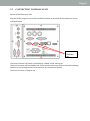
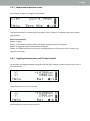
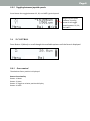
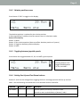
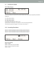
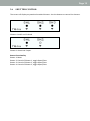
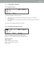
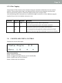
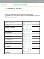
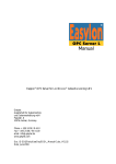
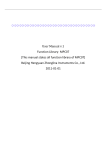
1
PS3J100 – User manual
Proscan III Interactive control Centre
Visit
web at
Prior on the
prior.com
Worldwide distribution
Version Issue – 1.2 (Jan 2013)
Prior Scientific, Ltd
Cambridge, UK
Prior Scientific, Inc
Rockland, MA. USA
Prior Scientific, GmbH
Jena, Germany
Prior Scientific KK
Tokyo, Japan
T. +44 (0) 1223 881711
E. [email protected]
T. +1 781-878-8442
E. [email protected]
T. +49 (0) 3641 675 650
E. [email protected]
T. +81-3-5652-8831
E. [email protected]
Visit Prior on the web at
prior.com
Page 2
Page 2
Table of Contents
Vi
Table of Contents
SECTION 1
IMPORTANT SAFETY INFORMATION
1.1
Important Safety Information
3
3
SECTION 2
GETTING STARTED
2.1
Identifying The Parts Of The Control Centre
2.2
Connecting to the Proscan III
2.3
XY Control
2.4
Z Control
2.5
Filter Control
2.6
Shutter Control
2.7
Lumen Control
2.8
Fourth Axis Theta Control
4
4
5
6
8
10
12
13
14
SECTION 3
CHANGING SETTINGS
3.1
Entering Setting Menu
3.2
Speed and Direction Settings
3.3
Encoders
3.4
TTL
3.5
Joystick Units
3.6
Versions
15
15
16
16
17
17
SECTION 4
COMPATIBILITY
4.1
Prior Controllers Compatible with PS3J100
19
19
SECTION 5
SPECIFICATIONS
5.1
Dimensions
20
20
SECTION 6
TROUBLESHOOTING
6.1
Troubleshooting
21
21
e web at
prior.com
SECTION 7
RETURNS AND REPAIRS
7.1
Returns and Repairs
22
22
Page 3
Section 1
1.1
SAFETY INFORMATION
IMPORTANT SAFETY INFORMATION
Save this manual as it contains important safety information and operating instructions.
• Do not get the system wet.
Page 6
Page 4
Section 2
2.1
GETTING STARTED
IDENTIFYING THE PARTS OF THE CONTROL CENTRE
Connection to ProScan III
Button 3
Button 2
Display
Button 1
(MENU)
Button 4
Left Hand
Wheel
Button 6
Button 5
Right Hand
Wheel
Joystick
Hand pad
Overview:
The Joystick always controls X and Y axis of the stage.
Button 1 is always the Menu button.
Button 5 is the speed control for the X and Y axis for the stage.
Button 6 is the speed control for the Z axis.
Buttons 1 – 4 functions are determined by the messages on the lower portion of the display
screen.
Right hand wheel is normally used for focus
Left hand wheel is usually used for focus unless in filter wheel screen when it controls filters.
Menus scroll though available options before returning to the first option.
For settings menu hold down Menu button for 3 seconds.
Page 5
Page 5
Page 5
2.2
CONNECTING TO PROSCAN III
Switch off the ProScan III unit.
Plug the RS232 plug into one of the two RS232 sockets on the back of the ProScan III unit as
indicated below.
Switch on the ProScan III unit.
RS232
Sockets
on
ProScan
III
The Control Centre will power up and display “PRIOR” while starting up.
The Control Centre will now display one of the relevant accessory screens from the following
sections or the settings menu if no accessories are attached to the PS3.
The Control Centre is ready to use.
Page 6
2.3
XY CONTROL
2.3.1 Absolute position screen
Stage Joystick speed
indicator. Pressing
button 6 will toggle
speed between 25, 50,
and 100%.
The XY control screen is displayed on start-up if a stage is connected to the system.
The absolute position is displayed in um.
If an E is present before the X or Y then the stage is encoded.
Button Functionality:
Button 1: Menu
Button 2: None
Button 3: Toggle to relative positional display format.
Button 4: Change the function of the Left and Right Wheels to fine control of the X and Y axis.
(Joystick still active)
The Joystick controls XY motion.
If a focus is attached in this mode the right and left wheels control focus.
2.3.2 Relative position screen
Press Button 3 “REL” to toggle to this display.
The absolute position is replaced by the relative position.
A Delta sign before X and Y indicates that the control centre is in Relative mode.
Button Functionality:
Button 1: Menu
Button 2: Zero relative position (does not affect absolute position of system).
Button 3: Toggle to measurement positional display.
Button 4: Change the function of the Left and Right Wheels to fine control of the X and Y axis.
(Joystick still active)
Page 7
Page 7
2.3.3 Measurement position screen
Press Button 3 “Meas” to toggle to this display.
The relative position is replaced by the distance from 0, (0 abs 0, or position when zero button
was pressed).
Button Functionality:
Button 1: Menu
Button 2: Zero relative position (does not affect absolute position of system).
Button 3: Toggle to measurement positional display.
Button 4: Change the function of the Left and Right Wheels to fine control of the X and Y axis.
(Joystick still active)
2.3.4 Toggling between focus and XY wheel control
Press button 4 to toggle between using the Left and right wheels to control focus or the X and Y
axis individually.
Press Button 4 to move to XY control
Press Button 4 to move to focus control
Page 8
2.3.5 Toggling between joystick speeds.
Press Button 6 to toggle between 25, 50, and 100% joystick speed.
Stage Joystick speed
indicator. Pressing
button 6 will toggle
speed between 25, 50,
and 100%.
2.4
Z CONTROL
Press Button 1 (Menu) to scroll thought the available options until the focus is displayed.
2.4.1
Focus control
The absolute focus position is displayed.
Button Functionality:
Button 1: Menu
Button 2: None
Button 3: Toggle to relative positional display.
Button 4: None
Page 9
2.4.2 Relative position screen
Press Button 3 “REL” to toggle to this display.
The absolute position is replaced by the relative position.
A Delta sign before Z indicates that the control centre is in Relative mode.
Button Functionality:
Button 1: Menu
Button 2: Zero relative position (does not affect absolute position of system).
Button 3: Toggle to absolute positional display.
Button 4: None
2.4.3 Toggling between joystick speeds.
Press Button 6 to toggle between 25, 50, and 100% joystick speed.
Focus Speed Indicator.
Pressing button 6 will
toggle speed between
25, 50, and 100%.
2.4.4 Setting Fast Up and Fast Down buttons.
Buttons 5 and 6 can be changed from toggling the focus and stage speed to be fast up and fast
down. Use the following command sent to the attached ProScan Controller.
Command
Arguments Response
Description
ICC CS152Z
s
Sets the speed s (in microns/s) of button 5 and 6.
R
Set to 0 to return to the default us of buttons 5 and 6.
ICC CS152Z
s
Returns the speed s (in microns/s) of button 5 and 6.
Page 10
2.5
FILTER CONTROL
2.5.1 Filter Screens
The screen displays the attached Filter wheels labelled with where they are physically attached to
ProScan III;
F1 is Filter wheel socket 1
F2 is Filter wheel socket 2
F3 is Filter wheel socket 3
Press Button 2 Sel each filter wheel in turn.
Displayed after the identifier is the position or name of the filter/attenuator.
The LumenPro systems will appear in this screen, see section 2.7.
2.5.2 Controlling Filter Wheels
Select F1: The left hand wheel controls the filter position of wheel 1.
Select F2: The left hand wheel controls the filter position of wheel 2.
Select F3: The left hand wheel controls the filter position of wheel 3.
Button Functionality:
Button 1: Menu
Button 2: Selects the next Filter Wheel
Button 3: Homes selected Filter Wheel
Button 4: None
Page 11
2.5.3 Filter Tagging
The positions of filter wheels can be named to help you remember which filters set are in
which location. These names called “tags” are displayed on the control centre display once
they have been set. Each Filter position in each filter wheel can be given a unique name.
Use the following ASCII commands sent via RS232 through a terminal or via the VBDemo
program supplied free on the Prior Website www.prior.com.
Command
Arguments Response
Description
7
W,T,P
Displays tag text for filter wheel w at position p.
Text
7,1,T,3 will respond with text for filter wheel 1 position 3.
7
W,T,P, text R
Writes text to memory for filter wheel W and Position P.
7,1,T,3,Dapi will set the tag for filter wheel 1 position 3 to “Dapi”
Tags are 6 characters log and are displayed in control centre display.
Page 12
2.6
SHUTTER CONTROL
The screen will display any attached standard shutters. Use the buttons to control the shutters.
Shutters 1 and 2 and 3 closed.
Shutter 1 closed and 2 open.
Button Functionality:
Button 1: Menu
Button 2: Control of Shutter 1, toggle Open/Close
Button 3: Control of Shutter 2, toggle Open/Close
Button 4: Control of Shutter 3, toggle Open/Close
Page 13
2.7
LUMENPRO CONTROL
2.7.1 LumenPro Screens
The LumenPro appears in the Filter screen as:
L6
LA
6 position filter wheel, displayed after the identifier is the position or name of the
filter/attenuator.
Lumen light attenuator, displayed after the identifier is the % light output of the Lumen
attenuator.
Press Button 2 Sel to toggle between the two controls.
2.7.2 Controlling the Lumen Accessories.
Select L6: The left hand wheel controls the filter position
Select LA: The left hand wheel controls the Attenuator position.
Button Functionality:
Button 1: Menu
Button 2: Selects the next accessory
Button 3: Homes selected accessory
Button 4: None
Page 14
2.7.3 Filter Tagging
The positions of filter wheels can be named to help you remember which filters set are in which
location. These names called “tags” are displayed on the control centre display once they have
been set. Each Filter position in each filter wheel can be given a unique name.
Use the following ASCII commands sent via RS232 through a terminal or via the VBDemo program
supplied free on the Prior Website www.prior.com.
Command
Arguments Response
Description
7
W,T,P
Displays tag text for filter wheel w at position p.
Text
7,1,T,3 will respond with text for filter wheel 1 position 3.
7
W,T,P,
R
text
Writes text to memory for filter wheel W and Position P.
7,1,T,3,Dapi will set the tag for filter wheel 1 position 3 to “Dapi”
Tags are 6 characters log and are displayed in control centre display.
2.8
FOURTH AXIS THETA CONTROL
Displays the current theta angle
Button Functionality:
Button 1: Exit to next menu
Button 2: Toggle thro angle step size, (0.1,1.0,10,90,180)
Button 3: Move step size anti-clockwise
Button 4: Move step size clockwise
Page 15
Section 3
3.1
CHANGING SETTINGS
ENTERING SETTING MENU
Hold down button 1 (Menu) for 3 seconds. The Control Centre will enter the settings
menu.
Only the settings applicable to the accessories attached will be displayed.
To change the setting use the right hand wheel, to scroll though setting use the left hand
wheel.
In the menu you have access to:
Stage XY speed settings
Stage Z speed settings
Joystick XY speed settings
Joystick Z speed settings
Stage X direction
Stage Y direction
Stage Z direction
Joystick X direction
Joystick Y direction
Joystick Z direction
TTL services
Encoder Information
Joystick Units
Page 16
3.2
SPEED AND DIRECTION SETTINGS
The Stage and Joystick speed can be set here in the control centre, this affects the speeds stored
and used in the ProScan III.
Press Button1 (Menu) to Exit settings menu.
Stage speed refers to the speed of the axis under computer control
Joy speed refers to the speed of the axis under Joystick Control
Stage direction refers to which direction is –ve and +ve when controlled via computer
Joy direction refers to which direction is –ve and +ve when controlled via Joystick (Change this to
changed the handedness of the Joystick).
Scroll to the option you require using the left hand wheel then change the option using the right
hand wheel.
3.3
ENCODERS
3.3.1 Encoder Settings
Scroll the left wheel to Stage, for XY encoders only available if encoder connected and detected
by ProScan III.
Scroll the left wheel to Focus, for Z encoders only available if encoder connected and detected by
ProScan III.
Button Functionality:
Button 1: Exit to main Menu
Button 2: none
Button 3: Toggle Encoder on / off
Button 4: Toggle Servo on ./ off
Encoder active means the encoder is used to provide positional feedback.
Servo active means the axis will attempt to remain at the given position.
Page 17
Page 17
Page 17
3.4
TTL
The TTL functionality of the ProScan III can be tested via the Control Centre, this is designed to
allow users to test the output of the system.
Scroll with the left hand wheel to select which TTL output is required.
Button Functionality:
Button 1: Exit setting menu
Button 2: None
Button 3: Send Pulse, (direction selected by button 4)
Button 4: Put signal High or Low.
3.5
JOYSTICK UNITS
The units of the joystick can be converted from the default value of microns into inches.
In the settings menu scroll with the left hand wheel until you come to the units menu
With the right hand wheel scroll backwards to select inches, scroll forward to return to microns.
Page 18
3.6
VERSIONS
The Joystick and controller firmware version are displayed.
Page 19
Section 4
4.1
COMPATIBILITY
PRIOR CONTROLLERS COMPATIBLE WITH PS3J100
The control centre is currently only compatible with ProScan III units.
Page 20
Section 5
5.1
SPECIFICATIONS
DIMENSIONS
Dimensions are in mm.
Page 21
Section 6
6.1
TROUBLESHOOTING
TROUBLESHOOTING
Checking your Joystick is centred and your buttons work.
To enter this mode, hold down Menu button on start-up.
X and Y is the displacement of the Joystick in X and Y.
L is the displacement of the digital encoder wheel on the left hand side.
R is the displacement of the digital encoder wheel on the right hand side.
Pushing the six buttons will change the associated triangle on the lower part of the screen to an
upside down solid triangle.
Problem:
Control Centre does not power up on start-up.
Solution:
Check connections with ProScan III, and power off and power on ProScan III.
Problem:
Sections of the Control centre do not respond, i.e., Joystick, or the wheels.
Solution:
Check the software to ensure they are not deactivated. (H and J commands)
(If the Joystick is deactivated it will display “Deactivated” on the screen.)
Page 21
Page 22
Section 7
7.1
RETURNS AND REPAIRS
RETURNS AND REPAIRS
Should you experience problems with your Plate Loading System and want to send it back for
service, warranty or otherwise, a Return Material Authorisation (RMA) number must be obtained
from the appropriate Prior Scientific office before returning any equipment. For North and South
America contact Prior Scientific Inc. and for the rest of the world call Prior Scientific Instruments
Limited on the telephone numbers shown below.
Prior Scientific Instruments Ltd,
3-4 Fielding Ind. Estate
Wilbraham Road,
Fulbourn,
Cambridge,
ENGLAND,
CB21 5ET
Tel: 01223 881711
Fax: 01223 881710
email: [email protected]
Prior Scientific KK
Kayabacho 3rd Nagaoka Bldg. 10F
2-7-10
Nihonbashi Kayabacho,
Chuo-Ku
Tokyo
103-0025
JAPAN
Tel: +81 (0) 3 5652 8831
Fax: +81 (0) 3 5652 8832
email: [email protected]
Prior Scientific Inc.
80 Reservoir Park Drive,
Rockland,
MA 02370-1062
USA
Tel: 781 878 8442
Fax: 781 878 8736
email: [email protected]
Prior Scientific GmbH
Wildenbruchstr. 15
D-07745
Jena
GERMANY
Tel: +49 (0)3641 675 650
Fax: +44 (0)3641 675 651
email: [email protected]