1
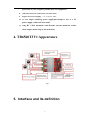
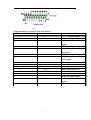
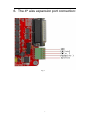
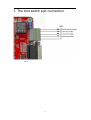
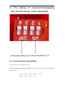
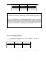
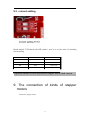
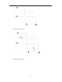
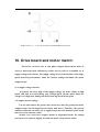
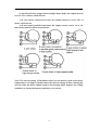
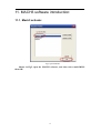
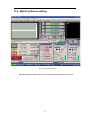
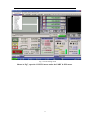
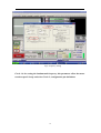
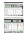
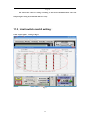
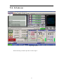
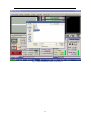
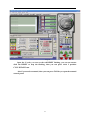
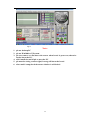
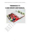
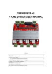
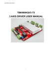
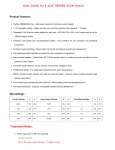
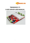
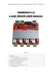
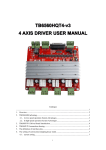
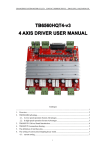
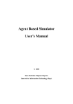
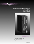
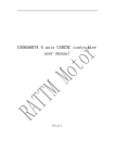
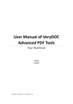
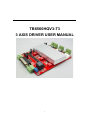
TB6560HQV3-T3
3 AXIS DRIVER USER MANUAL
1
CATALOGUE
1. Overview...........................................................................................................................2
2. TB6560AHQ advantag...................................................................................................................3
2.1、At low speed operation System Advantages.......................................................................3
2.2、In high-speed operation System Advantages......................................................................4
3. TB6560T3V1 Driver Board Introduction.......................................................................................4
4. TB6560T3V1connection drawing..................................................................................................5
5. The definition of parallel port pins.................................................................................................5
6. The connection of 4th axis ..............................................................................................................7
7. The connection of limit switch.......................................................................................................8
8. The setting of current,microstepping,decay mode..........................................................................9
8.1、current setting......................................................................................................................9
8.2、microstepping setting........................................................................................................10
8.3、decay mode setting............................................................................................................11
9. The connection of kinds of stepper motors...................................................................................11
10. The choice of stepper motor and power supply..........................................................................13
11. MACH software user manual.....................................................................................................15
11.1、Mach3 open.....................................................................................................................15
11.2、Mach3 sofware setting.....................................................................................................16
11.3、Limit switch’s mach3 setting...........................................................................................20
11.4、Run of the G code............................................................................................................21
1. Overview
The PC Engraving is a Multifunction Engraving Machine collects engrave
and Milling.The machine mainly applicable to Processing of a variety of mold
like : Embossing plate,Shoe mold, Button mold, zipper-mode, Text die and
stamping die design, equipment molds, glass molds and so on.The machine also
applies to the advertising industry like: Division licenses, signs, architectural
models, badges, badges, nameplates, panels, logo, numbers, signs, craft
decoration, furniture decoration and so on. Besides, applies to portrait,
landscape, calligraphy lettering, seals and other graphic art sculpture, YIN,
YANG Wen-profile, relief production.
Our shop products 3-axis engraving machine drive,using high-performance
dedicated micro-step away from the computer control chip TB6560, Open
microcomputer control according to user requirements to functional design to
the driver board, the composition of the minimum control system. he control
panel is suitable for any small and medium-driven two-phase or four-phase
hybrid stepper motor. And have current 0.6A, 1.2A, 1.8A, 2.5A 4 stalls adjustable
2
function, support MACH2, MACH3 Series software, support KCAM4 Series
software, extensive application and mold machining, engraving and other
graphic applications. As a result of new bipolar constant-current chopping
technique, high precision, the motor is running, little vibration, low noise,
smooth operation, safe and convenient, the vast number of DIY enthusiasts and
engraving machine manufacturers product of choice.
2. TB6560AHQ advantage
2.1 At low speed operation System Advantages
Low-speed operating system, is the clock frequency is not high, with small
current drive-based systems, such as the speed of a few per minute to 100 turn,
the user under the conditions in such applications, such as the use of traditional
driving scheme, or a result of integrated chips segmentation is too low, leaving
low-speed vibration is too large; or had to choose a high drive segments, so that
the cost of an unnecessary increase.
TB6560AHQ driver chip's advantages:
(1). Motor vibration, low noise: Because the chip comes with an optional sub2,4,16, enough to meet nearly every minute to switch from a few of the
applications.
(2). embedded drive less heat: chip built-in cooling large enough alone to support
small current-driven thermal requirements.
(3).support a variety of stepper motor selection: customers can choose a hybrid
or a slightly larger torque permanent magnet stepper motor, the motor work in
the allowed maximum torque of between 30-50%, the electrical costs of almost
unchanged; chip provides multi-range current set-up and current-decay mode,
supporting the same power index a variety of different parameters under the
stepper motor.
2.2 In high-speed operation System Advantages
High-speed operating system refers to a higher clock frequency, and a large
current drive-based systems, such as the speed of close to 1000 per minute to
switch, under the conditions of such application-driven programs such as the use
of traditional or integrated chip segment is too low due to , leaving the system
speed range is too small; or because of the excessive breakdown of the high
increase in cost, may also occur due to decline in high-frequency torque caused
by vibration and noise.
TB6560AHQ driver chip's advantages:
3
(1). motor vibration, low noise: As the chip comes with 16 sub-TB6560AHQ chip
functionality, to meet nearly every minute to switch from a few to the application
requirements, and automatically generates a pure sine wave control current, and
other high-integrated chip compared to the same high-speed torque is not only
not fall under the contrary, increase; TB6560AHQ chip can withstand the peak
due to the driving voltage of 40V, 3.5A peak current for the motor torque in the
large, high-speed continuous operation under the offer of the technical support.
(2). supports a variety of stepper motor selection: customers can choose a hybrid
moment slightly larger or permanent magnet stepper motor, so that the motor
operates at maximum torque of between 30-50%, the electrical costs of almost
unchanged; chip provides high-current set-up and multi-range current-decay
mode, supporting the same power index a variety of different parameters under
the stepper motor.
(3). an embedded easy to drive, small size cooling: large current drive, the chip surface to
facilitate cooling radiator outside the company can also be directly connected to the user's
original controller, metal shell, the embedded drives small size, easy to heat.
In short, due to a high degree of TB6560AHQ chip, the external circuit is
extremely simple, highly reliable, support NEMA23 and some NEMA34 stepper
motor tens to nearly turn the wide speed range applications, will enable CNC
equipment R & D costs and production costs both declined.
3. TB6560T3V1 Driver Board Introduction
The company introduced TB6560T3V1 is the company's accumulated years of
design experience drives that the design made of 3-axis engraving machine drive.
Main features except the 6560 itself, the other features are as follows:
1. it can drive three axis,The 4th axis expansion, to facilitate your needs 4axis machining when working
2.
Spindle relay output, easy to use software such as mach3 to control
spindle start and stop.
3.
Semi-flow control functions, and effective to stop the motor when the
current is reduced to a minimum.
4.
Interface with a fan, you can add fan under your choice.
5.
With 3 wire 0.8-3.5A (peak) rated output of two-phase adjustable-
current bipolar stepper motor drive;
6.
Standard parallel port interface, support for MACH2, KCAM4 series
software;
7.
With optical isolation and DCDC power supply isolation, the full
4
protection of your computer parallel port and equipment;
8.
with limit switch,can connection 4 aixs limit switch
9.
Support four microstepping ——1、1/2、1/8、1/16;
10. 12—36V single switching power supply,microchips to use as a 5V
power supply, stable and heat small
11. Using RC +7414 automatic semi-flow,the current automatic reduce
when stepper motor stop to down the heat
4. TB6560T3V1 Appearance
Fig 1
5. Interface and its definition
5
Fig 2
25-pin parallel port control is defined as follows:
DB25 control pin (PIN)
The pin of the drive board
1
EN
2
STEPX
3
DIRX
4
STEPY
5
DIRY
6
STEPZ
7
DIRZ
10
LIMIT-1
11
LIMIT-2
12
LIMIT-3
13
LIMIT-4
14
Relay
15
Blank
16
STEPB-
17
DIRB-
18-25
GND
Comment
All axes enable
X(First axis) pulse signal
X(First axis) direction of the
signal
Y(Second axis)pulse signal
Y(Second axis)direction of
the signal
Z(Third axis) pulse signal
Z (The third axis) direction
of the signal
Limit input interface 1
Limit input interface 2
Limit input interface 3
Limit input interface 4
B(4th axis) pulse signal
B(4th axis) direction of the
signal
6
6. The 4th aixs expansion port connection:
Fig 3
7
7. The limit switch port connection:
Fig 4
8
8. The setting of current,microstepping
and current-decay mode adjustable
8.1、Current-decay mode setting
Pls use 12-24V,>4A switching power supply
Board marked D1D2 (match with DIP swtich 1 and 2) to set the value of switching
current-decay
D1/D2:ON/ON——100%; ON/OF——25%;
OF/ON——50%; OF/OF——0%;
9
D1
D2
Working mode
ON
ON
Fast decay
OF
ON
50% fast decay
ON
OF
25%fast decay
OFF
OFF
Slow decay
Q: The stepper motor driver board the specific role of current-decay What is this?
A: The stepper motor is basically a breakdown of the way current subdivision law, according to the
phase current sine wave to be tangent to the current point as subdivision points. In the phase current to
reach sub-point control is necessary to control the current decay, otherwise it would be if there will be
no way to accurately point overshoot stay in the breakdown of perspective. The motor at different
speeds in different choices of decay mode. Fast decay at high speed, low speed when the slow decay.
Slow decay at high speed there will be vibrations, high noise problem. Low selection of quick decay
can lead to motor weakness and in severe cases closed position. Motor Control IC, the current decay is
the target of H-bridge switch the control mode. Slow decay, when the high side pipes closed, fast decay
time high or low side tubes are closed. Mixed decay is a first, a rapid decay and then a slow decay,
mixing ratio of decay time is also a result of chip and power are not the same as
8.2、microstepping setting
Board marked M1M2(match with DIP swtich 3 and 4) to set the value of
switching microstepping resolution
M1
M2
Working mode
OFF
ON
1/16
ON
ON
1/8
ON
OFF
1/2
OFF
OFF
1
Remark:For motor run smoothly, please try to select high segments, such as 1 / 16 microstepping
10
8.3、current setting
Board marked T1T2(match with DIP swtich 1 and 2) to set the value of switching
current setting
T1
T2
Current
ON
ON
25%*2.5A
OFF
ON
50%*2.5A
ON
OFF
75%*2.5A
OFF
OFF
100%*2.5A
Proposed current as close as possible stepper motor rated current
9. The connection of kinds of stepper
motors
4 lead wires stepper motor:
11
6 lead wires stepper motor:
8 lead wires stepper motor:
12
Stepper motor +A -A +B -B connection AP AM BP BM of board port
10. Drive board and motor match:
The driver can drive two or four phase stepper motors,motor drive in
order to obtain the most satisfactory results, need to select a reasonable set of
supply voltage and current. The supply voltage level of the decision of the highspeed electrical performance, while the current settings determine the motor
output torque.
(1) A supply voltage selected:
In general, the more high of the supply voltage, the more torque in high
speed, and able to avoid missing step at high speed. On the other hand, the
voltage is too high may damage the driver,also big shock in low speed
(2) output current settings:
For the same motor, the greater the current set value, the greater the motor
output torque, but the high heat for motor and driver. Therefore, the general
situation is that the current is set to supply long-term work machine when warm
but not too hot when the values.
1)when 4 or 6 lead wires stepper motors in high-speed mode: the output
current is set to equal or slightly less than the motor rated current value;
13
2) when 6 lead wires stepper motor in high torque mode: the output current
is set to 70% of motor rated current
3) 8 -wire motor connected in series: the output current is set to 70% of
motor rated current
4) 8 -wire motor parallel connection: the output current can be set to 1.4
times more than the motor rated current.
Note: The current setting 15-30 minutes after you run motors, such as the motor
temperature is too high, it should reduce the current settings.if after reducing the
current value, the motor output torque is not enough, please improve the cooling
conditions to ensure that motors and drives are not hot.
14
11. MACH3 software introduction:
11.1、Mach3 activate:
Fig 5 open MACH3
Shown in Fig5, open the MACH3 software, and then select mach3MILL
then OK!
15
11.2、Mach3 software setting:
Fig 6 mach3 main interface
Open the MACH3 as Fig6,there are some common buttons,then let us set up it!
16
Fig 7 mach3 setting menu
Shown in Fig7, open the CONFIG menu under the PORT & PIN menu.
17
Fig 8 frequency setting
Circle 1 is for setting the fundamental frequency, this parameter affect the motor
rotation speed. Set up and select Circle 2, configuration pin definitions
18
Fig 9 The pin setting of Dir,Step
19
Fig 10
Pls amend the software setting according to this board definition.then select the
Output Signas as Fig10,1 is Enable and 14 is relay.
11.3、Limit switch mach3 setting:
Click “input signal”,setting as Fig11
Fig 11
20
11.4、G-Code run:
Fig 12 Open G file
When all setting is ok,then open the G-code as Fig 12.
21
Fig 13 Open the MACH3 with G-code self test.
22
Fig 14
Open the G code, you can see the red RESET flashing, you can use mouse
click the RESET to stop the flashing, then you can press circle 2 position
CYCLESTART run.
Also if you need to manual, then you can press TAB key to open the manual
control panel
23
Fig 15
Note:
1. pls use desktop PC
2. pls use Win2000 or XP system
3. pls not connect or disconnect the motor when board is power on,otherwise
maybe burnt the ICs
4. after install the mach3 pls re-start the PC
5. pls must be wiring connect right,if wrong will burnt the board
6. after mach3 setup,check the motor whether is self-locked
24