1
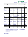
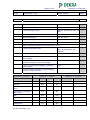
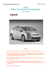
Test Report issued under the responsibility of:
TEST REPORT
IEC 60598-2-2
Luminaires
Part 2: Particular requirements:
Section Two – Recessed luminaires
Report Reference No......................:
3117604.50A
Date of issue.....................................:
2011-05-26
Total number of pages ......................
36 pages
CB Testing Laboratory...................:
DEKRA Testing and Certification China Ltd.
Address ............................................:
10F, #250 Jiangchangsan Road, Building 16, Headquarter
Economy Park Shibei Hi-Tech Park, Zhabei District, Shanghai,
200436, China
Applicant’s name............................:
Philips Lighting Luminaires (Shanghai) Co., Ltd.
Address ............................................:
No. 2688, Hu Yi Road, Jiading, Shanghai, 201801, P.R.China
Test specification:
Standard ...........................................:
IEC 60598-2-2:1996+A1:1997 used in conjunction with
IEC 60598-1:2008
Test procedure .................................:
CB
Non-standard test method…………..:
N/A
Test Report Form No......................:
IEC60598_2_2A
Test Report Form(s) Originator ........:
Intertek Semko AB
Master TRF.......................................:
2008-12
Copyright © 2008 IEC System for Conformity Testing and Certification of Electrical Equipment
(IECEE), Geneva, Switzerland. All rights reserved.
This publication may be reproduced in whole or in part for non-commercial purposes as long as the IECEE is acknowledged as
copyright owner and source of the material. IECEE takes no responsibility for and will not assume liability for damages resulting from
the reader's interpretation of the reproduced material due to its placement and context.
If this Test Report Form is used by non-IECEE members, the IECEE/IEC logo and the reference to the CB Scheme
procedure shall be removed.
This report is not valid as a CB Test Report unless signed by an approved CB Testing Laboratory and appended
to a CB Test Certificate issued by an NCB in accordance with IECEE 02.
Page 2 of 36
Report No.: 3117604.50A
Test item description .....................:
Ceiling Light
Trade Mark .......................................:
PHILIPS
Manufacturer ....................................:
Philips Lighting Luminaires (Shanghai) Co., Ltd.
No. 2688, Hu Yi Road, Jiading, Shanghai, 201801, P.R.China
Model/Type reference ......................:
RC600B/LED31S/W60L60; RC600B/LED40S/W60L60;
RC600B/LED31S/W60L60/AIR; RC600B/LED40S/W60L60/AIR;
RC600B/LED31S/W30L120; RC600B/LED40S/W30L120;
RC600B/LED31S/W30L120/AIR; RC600B/LED40S/W30L120/AIR;
RC600B/LED31S/ACL/W60L60; RC600B/LED40S/ACL/W60L60;
RC600B/LED31S/ACL/W60L60/AIR;RC600B/LED40S/ACL/W60L6
0/AIR; RC600B/LED31S/ACL/W30L120;
RC600B/LED40S/ACL/W30L120;RC600B/LED31S/ACL/W30L120/
AIR; RC600B/LED40S/ACL/W30L120/AIR
Ratings .............................................:
220-240 V~; 50/60 Hz; IP20; Class l;
RC600B/LED31S/W60L60: 40 W
RC600B/LED40S/W60L60: 55 W
RC600B/LED31S/W60L60/AIR: 40 W
RC600B/LED40S/W60L60/AIR: 55 W
RC600B/LED31S/W30L120: 40 W
RC600B/LED40S/W30L120: 55 W
RC600B/LED31S/W30L120/AIR: 40 W
RC600B/LED40S/W30L120/AIR: 55 W
RC600B/LED31S/ACL/W60L60: 40 W
RC600B/LED40S/ACL/W60L60: 55 W
RC600B/LED31S/ACL/W60L60/AIR: 40 W
RC600B/LED40S/ACL/W60L60/AIR: 55 W
RC600B/LED31S/ACL/W30L120: 40 W
RC600B/LED40S/ACL/W30L120: 55 W
RC600B/LED31S/ACL/W30L120/AIR: 40 W
RC600B/LED40S/ACL/W30L120/AIR: 55 W
TRF No. IEC60598_2_2A
Page 3 of 36
Report No.: 3117604.50A
Testing procedure and testing location:
CB Testing Laboratory:
DEKRA Testing and Certification China Ltd.
Testing location/ address ..........................: 10F, #250 Jiangchangsan Road, Building 16, Headquarter
Economy Park Shibei Hi-Tech Park, Zhabei District, Shanghai,
200436, China
Associated CB Laboratory:
Testing location/ address ..........................:
Tested by (name + signature) .........: Vicky Zhang
Approved by (+ signature)...............: Lix Li
Testing procedure: TMP
Tested by (name + signature) .........:
Approved by (+ signature)...............:
Testing location/ address ..........................:
Testing procedure: WMT
Tested by (name + signature) .........:
Witnessed by (+ signature) .............:
Approved by (+ signature)...............:
Testing location/ address ..........................:
Testing procedure: SMT
Tested by (name + signature) .........:
Approved by (+ signature)...............:
Supervised by (+ signature) ............:
Testing location/ address ..........................:
Testing procedure: RMT
Tested by (name + signature) .........:
Approved by (+ signature)...............:
Supervised by (+ signature) ............:
Testing location/ address ..........................:
TRF No. IEC60598_2_2A
Page 4 of 36
Report No.: 3117604.50A
Summary of testing:
Tests performed (name of test and test clause):
Testing location:
All applicable tests have been done in CBTL.
DEKRA Testing and Certification China Ltd.
10F, #250 Jiangchangsan Road, Building 16,
Headquarter Economy Park Shibei Hi-Tech Park,
Zhabei District, Shanghai, 200436, China
Summary of compliance with National Differences:
Pass
Copy of marking plate
TRF No. IEC60598_2_2A
Page 5 of 36
Test item particulars .............................................. :
Ceiling Light
Classification of installation and use ........................ :
Class I; normal use; IP20
Supply Connection ................................................... :
Screwless terminal block
.................................................................................. :
Type X attachment
.................................................................................. :
-
Report No.: 3117604.50A
Possible test case verdicts:
- test case does not apply to the test object............. :
N/A
- test object does meet the requirement................... :
P (Pass)
- test object does not meet the requirement............. :
F (Fail)
Testing..................................................................... :
-
Date of receipt of test item ....................................... :
2011-04
Date (s) of performance of tests............................... :
2011-04 to 2011-05
General remarks:
The test results presented in this report relate only to the object tested.
This report shall not be reproduced, except in full, without the written approval of the Issuing testing
laboratory.
"(See Enclosure #)" refers to additional information appended to the report.
"(See appended table)" refers to a table appended to the report.
Throughout this report a comma is used as the decimal separator.
Clause numbers between brackets refer to clauses in IEC 60598-1
Although the followings are not listed in test report, the following standards have also been taken into account:
- EN 60598-1:2008+A11:2009
- EN 60598-2-2:1997
- IEC 62471-1:2006
- EN 62471-1: 2008
- IEC/TR 62471-2:2009
Factory:
Shanghai FUFA Metals Co., LTD.
No.2770 Bao An RD. Malu Town Jiading Disrict Shanghai China 201801
This report should be read in conjunction with the attached pages concerned with the European group
differences and national differences of the standards EN 60598-2-2:1997 with the reference number of
3117604.50B. (2 pages)
TRF No. IEC60598_2_2A
Page 6 of 36
Report No.: 3117604.50A
General product information:
These are 16 models of ceiling Light with LED light in this report; these products can be distinguished as
two series according to difference of with or without dali controller.
For the model name,
‘31S’ means its lumen output is 3100 lm,
‘40S’ means its lumen output is 4000 lm;
‘ACL’ means this model has actiLume sensor;
‘W60L60’ means its dimension is 597 x 597 mm
‘W30L120’ means its dimension is 297 x 1197 mm
‘AIR’ means this model have air-condition hole
All the models have similar electrical construction and mechanical construction, just with difference listed
above, therefore model RC600B/LED40S/W60L60 which has the highest lumen output and without aircondition hole were selected to perform the type test, other model RC600B/LED40S/ACL/W60L60/AIR,
RC600B/LED31S/W60L60, RC600B/LED40S/W30L120/AIR and RC600B/LED31S/W30L120 were
selected to perform endurance test and insulation resistance and electronic strength test, and additional
construction test was performed on model RC600B/LED31S/W30L120
The product is classified as Exempt group according to IEC 62471-1:2006 and IEC/TR 62471-2:2009.The
test result was laid in test report 3117605.50A and 3117605.50B.
TRF No. IEC60598_2_2A
Page 7 of 36
Report No.: 3117604.50A
IEC 60598-2-2
Clause
Requirement + Test
2.2 (0)
GENERAL TEST REQUIREMENTS
2.2 (0.1)
Information for luminaire design considered
Yes
No
⎯
2.2 (0.3)
More sections applicable ........................................: Yes
No
⎯
2.4 (2)
CLASSIFICATION
P
2.4 (2.2)
Type of protection (Class 0 excluded).................. : Class I
⎯
2.4 (2.3)
Degree of protection (Requirement: Ordinary)..... : IP20
⎯
2.4 (2.4)
Luminaire suitable for direct mounting on normally Yes
flammable surfaces .............................................. :
No
⎯
Luminaire not suitable for direct mounting on
Yes
normally flammable surfaces................................ :
No
⎯
Luminaire suitable to be covered by insulating
Yes
material................................................................. :
No
⎯
Luminaire for normal use ..................................... : Yes
No
⎯
Luminaire for rough service ................................. : Yes
No
⎯
2.4 (2.5)
Result - Remark
Verdict
P
2.5 (3)
MARKING
P
2.5 (3.2)
Mandatory markings
P
Position of the marking
P
Format of symbols/text
P
Additional information
P
Language of instructions
P
2.5 (3.3.1)
Combination luminaires
N/A
2.5 (3.3.2)
Nominal frequency in Hz
P
2.5 (3.3.3)
Operating temperature
N/A
2.5 (3.3.4)
Symbol or warning notice
N/A
2.5 (3.3.5)
Wiring diagram
N/A
2.5 (3.3.6)
Special conditions
N/A
2.5 (3.3.7)
Metal halide lamp luminaire – warning
N/A
2.5 (3.3.8)
Limitation for semi-luminaires
N/A
2.5 (3.3.9)
Power factor and supply current
P
2.5 (3.3.10)
Suitability for use indoors
P
2.5 (3.3.11)
Luminaires with remote control
N/A
2.5 (3.3.12)
Clip-mounted luminaire – warning
N/A
2.5 (3.3)
TRF No. IEC60598_2_2A
Page 8 of 36
Report No.: 3117604.50A
IEC 60598-2-2
Clause
Requirement + Test
2.5 (3.3.13)
Specifications of protective shields
2.5 (3.3.14)
Symbol for nature of supply
2.5 (3.3.15)
Rated current of socket outlet
N/A
2.5 (3.3.16)
Rough service luminaire
N/A
2.5 (3.3.17)
Mounting instruction for type Y, type Z and some
type X attachments
N/A
2.5 (3.3.18)
Non-ordinary luminaires with PVC cable
N/A
2.5 (3.3.19)
Protective conductor current in instruction if
applicable
N/A
2.5 (3.3.20)
Provided with information if not intended to be
mounted within arms reach
N/A
2.5 (3.4)
Test with water
P
Test with hexane
P
Legible after test
P
Label attached
P
2.5.1 (-)
Warning notice, if not suitable for insulating
ceiling
P
2.6 (4)
CONSTRUCTION
P
2.6 (4.2)
Components replaceable without difficulty
P
2.6 (4.3)
Wireways smooth and free from sharp edges
P
2.6 (4.4)
Lampholders
N/A
2.6 (4.4.1)
Integral lampholder
N/A
2.6 (4.4.2)
Wiring connection
N/A
2.6 (4.4.3)
Lampholder for end-to-end mounting
N/A
2.6 (4.4.4)
Positioning
N/A
- pressure test (N) ................................................ :
N/A
After test the lampholder comply with relevant
standard sheets and show no damage
N/A
After test on single-capped lampholder the
lampholder have not moved from its position and
show no permanent deformation
N/A
- bending test (N) ................................................. :
N/A
After test the lampholder have not moved from its
position and show no permanent deformation
N/A
2.6 (4.4.5)
Peak pulse voltage
N/A
2.6 (4.4.6)
Centre contact
N/A
TRF No. IEC60598_2_2A
Result - Remark
Verdict
N/A
ac
P
Page 9 of 36
Report No.: 3117604.50A
IEC 60598-2-2
Clause
Requirement + Test
2.6 (4.4.7)
Parts in rough service luminaires resistant to
tracking
N/A
2.6 (4.4.8)
Lamp connectors
N/A
2.6 (4.4.9)
Caps and bases correctly used
N/A
2.6 (4.5)
Starter holders
N/A
Starter holder in luminaires other than class II
N/A
Starter holder class II construction
N/A
Terminal blocks
N/A
Tails
N/A
Unsecured blocks
N/A
2.6 (4.6)
Result - Remark
Verdict
2.6 (4.7)
Terminals and supply connections
P
2.6 (4.7.1)
Contact to metal parts
P
2.6 (4.7.2)
Test 8 mm live conductor
P
Test 8 mm earth conductor
P
2.6 (4.7.3)
Terminals for supply conductors
P
2.6 (4.7.3.1)
Welded connections:
N/A
- stranded or solid conductor
N/A
- spot welding
N/A
- welding between wires
N/A
- Type Z attachment
N/A
- mechanical test according to 15.8.2
N/A
- electrical test according to 15.9
N/A
- heat test according to 15.9.2.3 and 15.9.2.4
N/A
2.6 (4.7.4)
Terminals other than supply connection
2.6 (4.7.5)
Heat-resistant wiring/sleeves
N/A
2.6 (4.7.6)
Multi-pole plug
N/A
- test at 30 N
N/A
Switches:
N/A
- adequate rating
N/A
- adequate fixing
N/A
- polarized supply
N/A
- compliance with 61058-1 for electronic switches
N/A
2.6 (4.9)
Insulating lining and sleeves
N/A
2.6 (4.9.1)
Retainement
N/A
Method of fixing .................................................... :
N/A
2.6 (4.8)
TRF No. IEC60598_2_2A
P
Page 10 of 36
Report No.: 3117604.50A
IEC 60598-2-2
Clause
Requirement + Test
2.6 (4.9.2)
Insulated linings and sleeves
N/A
Resistant to a temperature > 20 °C to the wire
temperature or
N/A
a) & c) Insulation resistance and electric strength
N/A
b) Ageing test. Temperature (°C) ......................... :
N/A
2.6 (4.10)
Insulation of Class II luminaires
N/A
2.6 (4.10.1)
No contact, mounting surface – accessible metal
parts – wiring of basic insulation
N/A
Safe installation fixed luminaires
N/A
Capacitors and switches
N/A
Interference suppression capacitors according to
IEC 60384-14
N/A
Assembly gaps:
N/A
- not coincidental
N/A
- no straight access with test probe
N/A
Retainment of insulation:
N/A
- fixed
N/A
- unable to be replaced; luminaire inoperative
N/A
- sleeves retained in position
N/A
- lining in lampholder
N/A
2.6 (4.11)
Electrical connections
P
2.6 (4.11.1)
Contact pressure
P
2.6 (4.11.2)
Screws:
P
- self-tapping screws
P
2.6 (4.10.2)
2.6 (4.10.3)
Result - Remark
- thread-cutting screws
2.6 (4.11.3)
Verdict
N/A
Screw locking:
P
- spring washer
P
- rivets
P
2.6 (4.11.4)
Material of current-carrying parts
P
2.6 (4.11.5)
No contact to wood or mounting surface
P
2.6 (4.11.6)
Electro-mechanical contact systems
N/A
2.6 (4.12)
Mechanical connections and glands
P
2.6 (4.12.1)
Screws not made of soft metal
P
Screws of insulating material
Torque test: torque (Nm); part .............................. : Screw fixing enclosure, driver
and cord anchorage; 1,2 Nm
TRF No. IEC60598_2_2A
N/A
P
Page 11 of 36
Report No.: 3117604.50A
IEC 60598-2-2
Clause
Requirement + Test
Result - Remark
Torque test: torque (Nm); part .............................. : Screw fixing reflector; 0,6 Nm
Verdict
P
Torque test: torque (Nm); part .............................. :
N/A
2.6 (4.12.2)
Screws with diameter < 3 mm screwed into metal
N/A
2.6 (4.12.4)
Locked connections:
N/A
- fixed arms; torque (Nm)...................................... :
N/A
- lampholder; torque (Nm) .................................... :
N/A
- push-button switches; torque 0,8 Nm................. :
N/A
2.6 (4.12.5)
Screwed glands; force (Nm) ................................. :
N/A
2.6 (4.13)
Mechanical strength
P
2.6 (4.13.1)
Impact tests:
P
- fragile parts; energy (Nm)................................... :
N/A
- other parts; energy (Nm) .................................... : 0,35 Nm for enclosure, lens
and reflector
P
1) live parts
P
2) linings
N/A
3) protection
P
4) covers
P
2.6 (4.13.3)
Straight test finger
P
2.6 (4.13.4)
Rough service luminaires
N/A
- IP54 or higher
N/A
a) fixed
N/A
b) hand-held
N/A
c) delivered with a stand
N/A
d) for temporary installations and suitable for
mounting on a stand
N/A
2.6 (4.13.6)
Tumbling barrel
N/A
2.6 (4.14)
Suspensions and adjusting devices
N/A
2.6 (4.14.1)
Mechanical load:
P
A) four times the weight
P
B) torque 2,5 Nm
N/A
C) bracket arm; bending moment (Nm) ................ :
N/A
D) load track-mounted luminaires
N/A
E) clip-mounted luminaires, glass-shelve.
Thickness (mm) ................................................... :
N/A
Metal rod. diameter (mm) .................................... :
N/A
TRF No. IEC60598_2_2A
Page 12 of 36
Report No.: 3117604.50A
IEC 60598-2-2
Clause
Requirement + Test
Result - Remark
Verdict
Fixed luminaire or independent control gear
without fixing devices
N/A
Load to flexible cables
N/A
Mass (kg) ............................................................. :
N/A
Stress in conductors (N/mm²) .............................. :
N/A
Mass (kg) of semi-luminaire ................................ :
N/A
Bending moment (Nm) of semi-luminaire ............ :
N/A
Adjusting devices:
N/A
- flexing test; number of cycles ............................. :
N/A
- strands broken
N/A
- electric strength test afterwards
N/A
2.6 (4.14.4)
Telescopic tubes: cords not fixed to tube; no
strain on conductors
N/A
2.6 (4.14.5)
Guide pulleys
N/A
2.6 (4.14.6)
Strain on socket-outlets
N/A
2.6 (4.15)
Flammable materials:
P
- glow-wire test 650 °C
P
- spacing ≥ 30 mm
P
2.6 (4.14.2)
2.6 (4.14.3)
- screen withstanding test of 13.3.1
N/A
- screen dimensions
N/A
- no fiercely burning material
2.6 (4.15.2)
2.6 (4.16)
- thermal protection
N/A
- electronic circuits exempted
N/A
Luminaires made of thermoplastic material with lamp control gear
N/A
a) construction
N/A
b) temperature sensing control
N/A
c) surface temperature
N/A
Luminaires for mounting on normally flammable surfaces
No lamp control gear
2.6 (4.16.1)
2.6 (4.16.2)
P
(compliance with Section 12)
P
N/A
Lamp control gear spacing:
P
- spacing 35 mm
P
- spacing 10 mm
N/A
Thermal protection:
N/A
- in lamp control gear
N/A
- external
N/A
TRF No. IEC60598_2_2A
Page 13 of 36
Report No.: 3117604.50A
IEC 60598-2-2
Clause
Requirement + Test
Result - Remark
Verdict
- fixed position
N/A
- temperature marked lamp control gear
N/A
2.6 (4.16.3)
Design to satisfy the test of 12.6
2.6 (4.17)
Drain holes
N/A
Clearance at least 5 mm
N/A
2.6 (4.18)
Resistance to corrosion:
N/A
2.6 (4.18.1)
- rust-resistance
N/A
2.6 (4.18.2)
- season cracking in copper
N/A
2.6 (4.18.3)
- corrosion of aluminium
N/A
2.6 (4.19)
Ignitors compatible with ballast
N/A
2.6 (4.20)
Rough service vibration
N/A
2.6 (4.21)
Protective shield:
N/A
2.6 (4.21.1)
Shield fitted
N/A
Shield of glass if tungsten halogen lamps
N/A
2.6 (4.21.2)
Particles from a shattering lamp not impair safety
N/A
2.6 (4.21.3)
No direct path
N/A
2.6 (4.21.4)
Impact test on shield
N/A
Glow-wire test on lamp compartment
N/A
2.6 (4.22)
Attachments to lamps
N/A
2.6 (4.23)
Semi-luminaires comply Class II
N/A
2.6 (4.24)
UV radiation for tungsten halogen lamps and
metal halide lamps (Annex P)
N/A
2.6 (4.25)
No sharp point or edges
P
2.6 (4.26)
Short-circuit protection:
N/A
2.6 (4.26.1)
Uninsulated accessible SELV parts
N/A
2.6 (4.26.2)
Short-circuit test
N/A
2.6 (4.26.3)
Test chain according to Figure 29
N/A
2.7 (11)
CREEPAGE DISTANCES AND CLEARANCES
P
Working voltage (V) .............................................. : 220-240 V~ for driver input
275 Vdc for driver output
⎯
Voltage form
Sinusoidal
Non-sinusoidal
⎯
PTI
< 600
⎯
TRF No. IEC60598_2_2A
(see 12.6)
N/A
> 600
Page 14 of 36
Report No.: 3117604.50A
IEC 60598-2-2
Clause
Requirement + Test
Result - Remark
Impulse withstand category (Normal category II)
(Category III Annex U)
Category II
Category III
Verdict
⎯
Rated pulse voltage (kV) ...................................... : -
⎯
(1) Current-carrying parts of different polarity: cr
Driver separately approved
(mm); cl (mm) ....................................................... : For input of LED module.
Cl = 3,0 mm > 1,68 mm
Cr = 3,0 mm > 2,75 mm
P
(2) Current-carrying parts and accessible parts: cr Cl = 3,1 mm > 1,68 mm
(mm); cl (mm) ....................................................... : Cr = 3,1 mm > 2,75 mm
P
(3) Parts becoming live due to breakdown of
basic insulation and metal parts:
cr (mm); cl (mm) ................................................... :
N/A
(4) Outer surface of cable where it is clamped and
metal parts: cr (mm); cl (mm) ............................... :
N/A
(5) Not used
⎯
(6) Current-carrying parts and supporting surface: Cl = 3,1 mm > 1,68 mm
cr (mm); cl (mm) ................................................... : Cr = 3,1 mm > 2,75 mm
P
2.8 (7)
PROVISION FOR EARTHING
P
2.8 (7.2.1
+ 7.2.3)
Accessible metal parts
P
Metal parts in contact with supporting surface
P
Resistance < 0,5 Ω
Self-tapping screws used
0,1 Ω
P
P
Thread-forming screws
N/A
Thread-forming screw used in a grove
N/A
Earth makes contact first
N/A
2.8 (7.2.2
+ 7.2.3)
Earth continuity in joints etc.
N/A
2.8 (7.2.4)
Locking of clamping means
P
Compliance with 4.7.3
P
Terminal blocks with integrated screwless
earthing contacts tested according Annex V
N/A
2.8 (7.2.5)
Earth terminal integral part of connector socket
N/A
2.8 (7.2.6)
Earth terminal adjacent to mains terminals
P
2.8 (7.2.7)
Electrolytic corrosion of the earth terminal
P
2.8 (7.2.8)
Material of earth terminal
P
Contact surface bare metal
P
TRF No. IEC60598_2_2A
Page 15 of 36
Report No.: 3117604.50A
IEC 60598-2-2
Clause
Requirement + Test
2.8 (7.2.10)
Class II luminaire for looping-in
N/A
Double or reinforced insulation to functional earth
N/A
2.8 (7.2.11)
2.9 (14)
2.9 (15)
Result - Remark
Verdict
Earthing core coloured green-yellow
P
Length of earth conductor
N/A
SCREW TERMINALS
N/A
Separately approved; component list
(see Annex 1)
N/A
Part of the luminaire
(see Annex 3)
N/A
SCREWLESS TERMINALS AND ELECTRICAL CONNECTIONS
P
Separately approved; component list
(see Annex 1)
P
Part of the luminaire
(see Annex 4)
N/A
2.10 (5)
EXTERNAL AND INTERNAL WIRING
P
2.10 (5.2)
Supply connection and external wiring
P
2.10 (5.2.1)
Means of connection............................................. : Screwless terminal block
P
2.10 (5.2.2)
Type of cable ........................................................ :
N/A
2
Nominal cross-sectional area (mm²)..................... : 3 x 1,0…1,5 mm
P
Cables equal to IEC 60227 or IEC 60245
P
2.10 (5.2.3)
Type of attachment, X, Y or Z
Type X
P
2.10 (5.2.5)
Type Z not connected to screws
2.10 (5.2.6)
Cable entries:
P
- suitable for introduction
P
- adequate degree of protection
P
N/A
2.10 (5.2.7)
Cable entries through rigid material have rounded
edges
N/A
2.10 (5.2.8)
Insulating bushings:
N/A
- suitably fixed
N/A
- material in bushings
N/A
- material not likely to deteriorate
N/A
- tubes or guards made of insulating material
N/A
2.10 (5.2.9)
Locking of screwed bushings
N/A
2.10 (5.2.10)
Cord anchorage:
P
- covering protected from abrasion
P
- clear how to be effective
P
TRF No. IEC60598_2_2A
Page 16 of 36
Report No.: 3117604.50A
IEC 60598-2-2
Clause
2.10
(5.2.10.1)
Requirement + Test
Result - Remark
Verdict
- no mechanical or thermal stress
P
- no tying of cables into knots etc.
P
- insulating material or lining
P
Cord anchorage for type X attachment:
P
a) at least one part fixed
P
b) types of cable
P
c) no damaging of the cable
P
d) whole cable can be mounted
P
e) no touching of clamping screws
P
f) metal screw not directly on cable
P
g) replacement without special tool
P
Glands not used as anchorage
N/A
Labyrinth type anchorages
N/A
2.10
(5.2.10.2)
Adequate cord anchorage for type Y and type Z
attachment
N/A
2.10
(5.2.10.3)
Tests:
P
- impossible to push cable; unsafe
P
2
- pull test: 25 times; pull (N) .................................. : 60 N for 3 x 1,0 mm
80 N for 3 x 1,5 mm2
P
- torque test: torque (Nm) ..................................... : 0,25 Nm for 3 x 1,0 mm2
0,35 Nm for 3 x 1,5 mm2
P
- displacement ≤ 2 mm
P
- no movement of conductors
P
- no damage of cable or cord
P
2.10 (5.2.11)
External wiring passing into luminaire
N/A
2.10 (5.2.12)
Looping-in terminals
N/A
2.10 (5.2.13)
Wire ends not tinned
P
2.10 (5.2.14)
2.10 (5.2.16)
2.10 (5.2.17)
Wire ends tinned: no cold flow
N/A
Mains plug same protection
N/A
Class III luminaire plug
N/A
Appliance inlets (IEC 60320)
N/A
Appliance couplers of class II type
N/A
No standardized interconnecting cables properly
assembled
N/A
TRF No. IEC60598_2_2A
Page 17 of 36
Report No.: 3117604.50A
IEC 60598-2-2
Clause
Requirement + Test
Result - Remark
Verdict
2.10 (5.2.18)
Used plug in accordance with
N/A
- IEC 60083
N/A
- other standard
N/A
2.10 (5.3)
Internal wiring
P
2.10 (5.3.1)
Internal wiring of suitable size and type
P
Through wiring
N/A
- not delivered/ mounting instruction
N/A
- factory assembled
N/A
- socket outlet loaded (A)...................................... :
N/A
- temperatures ...................................................... : (see Annex 2)
N/A
Green-yellow for earth only
N/A
2.10 (5.3.1.1) Internal wiring connected directly to fixed wiring
P
2
Cross-sectional area (mm²) .................................. : 0,5 - 1,0 mm for other
internal wiring
P
Insulation thickness
P
Extra insulation added where necessary
N/A
2.10 (5.3.1.2) Internal wiring connected to fixed wiring via internal current-limiting device
Adequate cross-sectional area and insulation
thickness
24 AWG for wiring connecting
to the connector in the PCB
P
P
2.10 (5.3.1.3) Double or reinforced insulation for class II
N/A
2.10 (5.3.1.4) Conductors without insulation
N/A
2.10 (5.3.1.5) SELV current-carrying parts
N/A
2.10 (5.3.1.6) Insulation thickness other than PVC or rubber
N/A
2.10 (5.3.2)
Sharp edges etc.
P
No moving parts of switches etc.
N/A
Joints, raising/lowering devices
N/A
Telescopic tubes etc.
N/A
No twisting over 360°
N/A
Insulating bushings:
N/A
- suitable fixed
N/A
- material in bushings
N/A
- material not likely to deteriorate
N/A
- cables with protective sheath
N/A
2.10 (5.3.4)
Joints and junctions effectively insulated
N/A
2.10 (5.3.5)
Strain on internal wiring
N/A
2.10 (5.3.3)
TRF No. IEC60598_2_2A
Page 18 of 36
Report No.: 3117604.50A
IEC 60598-2-2
Clause
Requirement + Test
2.10 (5.3.6)
Wire carriers
2.10 (5.3.7)
Wire ends not tinned
Wire ends tinned: no cold flow
Result - Remark
Verdict
N/A
P
N/A
2.11 (8)
PROTECTION AGAINST ELECTRIC SHOCK
P
2.11 (8.2.1)
Live parts not accessible with standard test finger
P
Basic insulated parts not used on the outer
surface without appropriate protection
P
Basic insulated parts not accessible with standard
test finger on portable and adjustable luminaires
N/A
Basic insulated parts not accessible with Ø 50
mm probe from outside, within arms reach, on
wall-mounted luminaires
N/A
Lamp and starterholders in portable and
adjustable luminaires comply with double or
reinforced insulation requirements
N/A
Basic insulation only accessible under lamp or
starter replacement
N/A
Protection in any position
Double-ended tungsten filament lamp
Insulation lacquer not reliable
2.11 (8.2.2)
P
N/A
P
Double-ended high pressure discharge lamp
N/A
Relevant warning according to 3.2.18 fitted to the
luminaire
N/A
Portable luminaire adjusted in most unfavourable
position
N/A
2.11 (8.2.3.a) Class II luminaire:
N/A
- basic insulated metal parts not accessible during
starter or lamp replacement
N/A
- basic insulation not accessible other than during
starter or lamp replacement
N/A
- glass protective shields not used as
supplementary insulation
N/A
2.11 (8.2.3.b) BC lampholder of metal in class I luminaires shall
be earthed
N/A
2.11 (8.2.3.c) Class III luminaires with exposed SELV parts:
N/A
Ordinary luminaire:
N/A
- touch current ...................................................... :
N/A
- no-load voltage ................................................... :
N/A
TRF No. IEC60598_2_2A
Page 19 of 36
Report No.: 3117604.50A
IEC 60598-2-2
Clause
2.11 (8.2.4)
Requirement + Test
Result - Remark
Verdict
Other than ordinary luminaire:
N/A
- nominal voltage ................................................. :
N/A
Portable luminaire:
N/A
- protection independent of supporting surface
N/A
- terminal block completely covered
N/A
2.11 (8.2.5)
Compliance with the standard test finger or
relevant probe
P
2.11 (8.2.6)
Covers reliably secured
P
2.11 (8.2.7)
Discharging of capacitors ≥ 0,5 μF
P
Portable plug connected luminaire with capacitor
N/A
Other plug connected luminaire with capacitor
N/A
Discharge device on or within capacitor
N/A
Discharge device mounted separately
N/A
2.12 (12)
ENDURANCE TEST AND THERMAL TEST
P
2.12 (12.3)
Endurance test:
P
- mounting-position ............................................... : Normal position
⎯
- test temperature (°C) .......................................... : 35 °C
⎯
- total duration (h) ................................................. : 240 h
⎯
- supply voltage: Un factor; calculated voltage (V): 264 V~
⎯
- lamp used ........................................................... : As delivered
⎯
After endurance test:
P
- no part unserviceable
P
- luminaire not unsafe
P
2.12 (12.3.2)
- no damage to track system
N/A
- marking legible
P
- no cracks, deformation etc.
P
2.12 (12.4)
Thermal test (normal operation)
(see Annex 2)
P
2.12 (12.5)
Thermal test (abnormal operation)
(see Annex 2)
P
2.12 (12.6)
Thermal test (failed lamp control gear condition):
2.12 (12.6.1)
Through wiring or looping-in wiring loaded by a
current of (A) ........................................................ :
⎯
- case of abnormal conditions............................... :
⎯
- electronic lamp control gear
- measured winding temperature (°C): at 1,1 Un . :
TRF No. IEC60598_2_2A
N/A
N/A
⎯
Page 20 of 36
Report No.: 3117604.50A
IEC 60598-2-2
Clause
2.12 (12.6.2)
Requirement + Test
Result - Remark
Verdict
- measured mounting surface temperature (°C) at
1,1 Un ................................................................... :
N/A
- calculated mounting surface temperature (°C) .. :
N/A
- track-mounted luminaires
N/A
Temperature sensing control
N/A
- case of abnormal conditions............................... :
⎯
- thermal link
N/A
- manual reset cut-out
N/A
- auto reset cut-out
N/A
- measured mounting surface temperature (°C)... :
N/A
- track-mounted luminaires
N/A
2.12 (12.7)
Thermal test (failed lamp control gear in plastic luminaires):
N/A
2.12 (12.7.1)
Luminaire without temperature sensing control
N/A
2.12
(12.7.1.1)
Luminaire with fluorescent lamp ≤ 70W
N/A
Test method 12.7.1.1 or Annex V......................... :
Test according to 12.7.1.1:
2.12
(12.7.1.2)
⎯
N/A
- case of abnormal conditions
⎯
- Ballast failure at supply voltage (V) ................... :
⎯
- Components retained in place after the test
N/A
- Test with standard test finger after the test
N/A
Test according to Annex V:
N/A
- case of abnormal conditions
⎯
- measured winding temperature (°C): at 1,1 Un.. :
⎯
- measured temperature of fixing point/exposed
part (°C): at 1,1 Un................................................ :
⎯
- calculated temperature of fixing point/exposed
part (°C) ................................................................ :
⎯
Ball-pressure test:
N/A
- part tested; temperature (°C).............................. :
N/A
- part tested; temperature (°C).............................. :
N/A
Luminaire with discharge lamp, fluorescent lamp > 70W, transformer > 10 VA
N/A
- case of abnormal conditions
⎯
- measured winding temperature (°C): at 1,1 Un.. :
⎯
TRF No. IEC60598_2_2A
Page 21 of 36
Report No.: 3117604.50A
IEC 60598-2-2
Clause
2.12
(12.7.1.3)
Requirement + Test
Result - Remark
- measured temperature of fixing point/exposed
part (°C): at 1,1 Un................................................ :
⎯
- calculated temperature of fixing point/exposed
part (°C) ................................................................ :
⎯
Ball-pressure test:
N/A
- part tested; temperature (°C).............................. :
N/A
- part tested; temperature (°C).............................. :
N/A
Luminaire with short circuit proof transformers
≤ 10 VA
N/A
⎯
- case of abnormal conditions
2.12 (12.7.2)
Verdict
- Components retained in place after the test
N/A
- Test with standard test finger after the test
N/A
Luminaire with temperature sensing control
N/A
- thermal link
Yes
No
⎯
- manual reset cut-out
Yes
No
⎯
- auto reset cut-out
Yes
No
⎯
- case of abnormal conditions
⎯
- highest measured temperature of fixing
point/exposed part (°C):........................................ :
⎯
Ball-pressure test:
N/A
- part tested; temperature (°C).............................. :
N/A
- part tested; temperature (°C).............................. :
N/A
2.13 (9)
RESISTANCE TO DUST, SOLID OBJECTS AND MOISTURE
P
2.13 (9.2)
Tests for ingress of dust, solid objects and moisture:
P
- classification according to IP .............................. : IP 20
⎯
- mounting position during test ............................. : Recessed
⎯
- fixing screws tightened; torque (Nm).................. : -
⎯
- tests according to clauses .................................. : 9.2.0
⎯
- electric strength test afterwards
P
a) no deposit in dust-proof luminaire
N/A
b) no talcum in dust-tight luminaire
N/A
c) no trace of water on current-carrying parts or
SELV parts or where it could become a hazard
N/A
d) i) For luminaires without drain holes – no water
entry
N/A
TRF No. IEC60598_2_2A
Page 22 of 36
Report No.: 3117604.50A
IEC 60598-2-2
Clause
Requirement + Test
Result - Remark
Verdict
d) ii) For luminaires with drain holes – no
hazardous water entry
N/A
e) no water in watertight luminaire
N/A
f) no contact with live parts (IP 2X)
P
f) no entry into enclosure (IP 3X and IP 4X)
N/A
f) no contact with live parts (IP3X and IP4X)
N/A
g) no trace of water on part of lamp requiring
protection from splashing water
N/A
h) no damage of protective shield or glass
envelope
N/A
25 °C; 93%
2.13 (9.3)
Humidity test 48 h
2.14 (10)
INSULATION RESISTANCE AND ELECTRIC STRENGTH
P
2.14 (10.2.1)
Insulation resistance test
P
Cable or cord covered by metal foil or replaced by -a metal rod of mm Ø ............................................ :
⎯
Insulation resistance (MΩ)
⎯
SELV:
N/A
- between current-carrying parts of different
polarity .................................................................. :
N/A
- between current-carrying parts and mounting
surface .................................................................. :
N/A
- between current-carrying parts and metal parts
of the luminaire ..................................................... :
N/A
Other than SELV:
- between live parts of different polarity................ :
P
N/A
- between live parts and mounting surface........... : 1000 MΩ
P
- between live parts and metal parts..................... : 1000 MΩ
P
- between live parts of different polarity through
action of a switch .................................................. :
2.14 (10.2.2)
P
Electric strength test
N/A
P
Dummy lamp
N/A
Luminaires with ignitors after 24 h test
N/A
Luminaires with manual ignitors
N/A
Test voltage (V):
SELV:
TRF No. IEC60598_2_2A
P
N/A
Page 23 of 36
Report No.: 3117604.50A
IEC 60598-2-2
Clause
Requirement + Test
Result - Remark
Verdict
- between current-carrying parts of different
polarity .................................................................. :
N/A
- between current-carrying parts and mounting
surface .................................................................. :
N/A
- between current-carrying parts and metal parts
of the luminaire ..................................................... :
N/A
Other than SELV:
- between live parts of different polarity................ :
P
N/A
- between live parts and mounting surface........... : 1550 V
P
- between live parts and metal parts..................... : 1550 V
P
- between live parts of different polarity through
action of a switch .................................................. :
N/A
2.14 (10.3)
Touch current (mA)............................................... : 0,2 mA <0,7 mA
P
2.15 (13)
RESISTANCE TO HEAT, FIRE AND TRACKING
P
2.15 (13.2.1)
Ball-pressure test:
P
- part tested; temperature (°C).............................. : PCB; 125 °C
P
- part tested; temperature (°C).............................. :
2.15 (13.3.1)
Needle flame test (10 s):
P
- part tested........................................................... : PCB
P
- part tested........................................................... :
2.15 (13.3.2)
2.15 (13.4.1)
N/A
N/A
Glow-wire test (650°C):
P
- part tested........................................................... : Lens
P
- part tested........................................................... : Reflector
P
- part tested........................................................... : PCB
P
- part tested........................................................... : Connector
P
Tracking test: part tested ...................................... :
TRF No. IEC60598_2_2A
N/A
Page 24 of 36
Report No.: 3117604.50A
IEC 60598-2-2
Clause
Requirement + Test
Result - Remark
Verdict
P
ANNEX 1: components
manufacturer/
trademark
type/model
technical data
B
BJB
46.413
16 A; 450 V; 1…2,5 IEC 60998-22
1
mm
VDE
Terminal block
B
Yuyao City Lixun
Electronics Co.,
Ltd.
PA-LX-18
500 V; 16 A 0,752
2,5 mm ; T110
IEC 60998-21
VDE
Terminal block
B
Yuyao City Lixun
Electronics Co.,
Ltd.
PA10
500 V; T110; 2,5
2
mm
IEC 60998-21
VDE
LED Driver
B
Xitanium 75W 02Philips electronical
0.4A 200V TD
Co.,Ltd
230V
220-240 Vac; tc=75 EN 61347-2℃;Uout=275 Vdc
13
ENEC05
LED
C
LG Innotek
LEMWS59T80JZ00
2,9 - 3,4 V; 150400 mA
IEC 60598-1
Tested in
appliance
PCB
C
LG Innotek
LARWT270RAAAA V-0
IEC 60598-1
Tested in
appliance
Internal wiring
connecting to
connector in PCB
C
LTK Technologies
Co., Ltd
--
24 AWG
(7/32AWG)TS*1C
IEC 60598-1
Tested in
appliance
Internal wire
C
SHANGHAI
PANDA WIRE &
CABLE CO.,LTD.
60227IEC07(BV90)
300/500 V; 0,5-2,5
mm²
IEC 60598-1
Tested in
appliance
Internal wire
C
Shanghai Sunqiao
Electric Wire &
Cable (Group)
Co., Ltd.
60227IEC06
(RV)
300/500 V; 0,5-1,0
mm²
IEC 60598-1
Tested in
appliance
Actilume sensor
B
Philips
LRI 1653/01
Ta=0…55℃
EN 61347-211
ENEC05
Actilume controller
B
Philips
LCC 1653/00
50/60 Hz
EN 61347-211
ENEC05
Connector
C
JST
PAP-07V-S
PA66; UL94V-0
IEC 60598-1
Tested in
appliance
Connector
C
MOLEX
5034730200
PBT; UL94V-0
IEC 60598-1
Tested in
appliance
object/part No.
code
Supply terminal
block
230 V~
standard
mark(s) of
conformity
The codes above have the following meaning:
A
- The component is replaceable with another one, also certified, with equivalent characteristics
B
- The component is replaceable if authorised by the test house
C
- Integrated component tested together with the appliance
D
- Alternative component
TRF No. IEC60598_2_2A
Page 25 of 36
Report No.: 3117604.50A
IEC 60598-2-2
Clause
Requirement + Test
Result - Remark
Verdict
ANNEX 2: temperature measurements, thermal tests of Section 12
P
Type reference .....................................................: RC600B/LED40S/W60L60
⎯
Lamp used............................................................: As delivered
⎯
Lamp control gear used .......................................: Xitanium 75W 02-0.4A 200V TD
230V
⎯
Mounting position of luminaire .............................: Recessed
⎯
Supply wattage (W)..............................................: 54,8 W at 240 V
⎯
Supply current (A) ................................................: 0,235 A
⎯
Calculated power factor .......................................: 0,972
⎯
Table: measured temperatures corrected for ta = 25 °C:
P
- abnormal operating mode ..................................: Short-circuit the output of LED
driver, and the product was
protected
⎯
- test 1: rated voltage ...........................................: 240 V
⎯
254,4 V
- test 2: 1,06 times rated voltage or 1,05 times
rated wattage........................................................:
⎯
- test 3: Load on wiring to socket-outlet,
1,06 times voltage or 1,05 times wattage ............:
⎯
264 V
- test 4: 1,1 times rated voltage or 1,05 times
rated wattage........................................................:
⎯
Through wiring or looping-in wiring loaded by a
current of A during the test ..................................:
⎯
Clause 12.4 – normal
temperature (°C) of part
Clause 12.5 – abnormal
test 1
test 2
test 3
limit
test 4
limit
Lens
-
36,2
-
90
-
-
Reflector
-
30,2
90
-
-
Internal wire connecting to
driver
-
33,5
90
-
-
Internal wire connecting to
LED module
-
34,5
90
-
-
PCB
-
50,5
130
-
-
Connector
-
35,0
-
130
-
-
Screwless terminal block
-
30,7
-
110
-
-
Earthing wire
-
31,1
-
90
-
-
TRF No. IEC60598_2_2A
-
Page 26 of 36
Report No.: 3117604.50A
IEC 60598-2-2
Clause
Requirement + Test
Result - Remark
Verdict
Cord anchorage
-
29,9
-
75
-
-
Mounting surface
-
38,4
-
90
25
130
48,0
-
-
85
-
-
-
34,4
-
90
-
-
tc
Enclosure of Actilumen
controller
TRF No. IEC60598_2_2A
Page 27 of 36
Report No.: 3117604.50A
IEC 60598-2-2
Clause
Requirement + Test
Result - Remark
ANNEX 3: screw terminals (part of the luminaire)
ANNEX 4: screwless terminals (part of the luminaire)
TRF No. IEC60598_2_2A
Verdict
N/A
N/A
Page 28 of 36
Annex user manual:
TRF No. IEC60598_2_2A
Report No.: 3117604.50A
Page 29 of 36
Annex user manual:
TRF No. IEC60598_2_2A
Report No.: 3117604.50A
Page 30 of 36
Annex pictures:
Top view without air-condition hole for series
RC600B/LEDXXS/(ACL)/W60L60
Top view with air-condition hole for series
RC600B/LEDXXS/(ACL)/W60L60/AIR
TRF No. IEC60598_2_2A
Report No.: 3117604.50A
Page 31 of 36
Report No.: 3117604.50A
Annex pictures (continued):
Bottom view for series RC600B/LEDXXS/(ACL)/W60L60/(AIR)
Side view for RC600B/LEDXXS/(ACL)/W60L60/(AIR)
TRF No. IEC60598_2_2A
Page 32 of 36
Report No.: 3117604.50A
Annex pictures (continued):
Top view for series RC600B/LEDXXS/(ACL)/W30L120/(AIR)
Bottom view for series RC600B/LEDXXS/(ACL)/W30L120/(AIR)
TRF No. IEC60598_2_2A
Page 33 of 36
Annex pictures (continued):
Sensor
Back of the sensor
TRF No. IEC60598_2_2A
Report No.: 3117604.50A
Page 34 of 36
Annex pictures (continued):
Earthing terminal
Fixing rivets
TRF No. IEC60598_2_2A
Report No.: 3117604.50A
Page 35 of 36
Annex pictures (continued):
Internal view for RC600B/LEDXXS/(ACL)/W60L60/(AIR)
Internal view for RC600B/LEDXXS/(ACL)/W30L120/(AIR)
TRF No. IEC60598_2_2A
Report No.: 3117604.50A
Page 36 of 36
Annex pictures (continued):
Internal view for RC600B/LEDXXS/(ACL)/W30L120/(AIR)
S
Sensor
TRF No. IEC60598_2_2A
Report No.: 3117604.50A