1
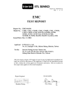
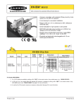
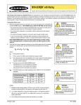
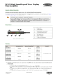
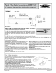
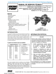
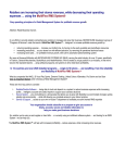
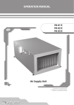
MINI-BEAM® Plastic Fiber Optic Sensors
Self-contained DC-operated Sensors for use with Banner Plastic Fiber Optics
MINI-BEAM Plastic Fiber Optic Sensor Features
•
Compact, modulated, self-contained visible red fiber optic sensors for 10-30V dc
operation
•
Useable in opposed and diffuse fiber optic modes with Banner plastic fiber optic
assemblies
•
Switch-selectable for light operate or dark operate
•
Includes Banner’s exclusive† AID™ alignment system
•
Highly-repeatable 1 millisecond response
•
Both sourcing and sinking outputs (150 mA max. each); continuous overload and
short-circuit protected
•
Rugged, epoxy-encapsulated construction: meets NEMA standards 1, 2, 3, 3S, 4,
4X, 6, 12 and 13; IEC IP67
†
U.S. Patent 4356393
Visible red, 650 nm
MINI-BEAM Plastic Fiber Optic Models
Models*
Range
Cable**
Supply
Voltage
Output
Type
Excess Gain
Beam Pattern
Diffuse mode performance based on 90% reflectance white test card
1000
E
X
C
E
S
S
SM312FP
SM2A312FP
Opposed Mode
Plastic Fibers
100
SM312FP
SM312FPQD
Range
varies
by
sensing
mode
and
fiber
optics
used
10-30V dc
4-Pin
Euro-style QD
10
Bipolar
NPN/PNP
1.2 in
0.6 in
0
PIT26U Fiber
PIT46U
PIT26U
10 mm
.40 in
100 mm
4.0 in
0.6 in
30 mm
1.2 in
1.8 in
0
1000 mm
40 in
25 mm
1 in
50 mm
2 in
75 mm 100 mm 125 mm
3 in
4 in
5 in
DISTANCE
DISTANCE
1000
E
X
C
E
S
S
SM312FP
SM2A312FP
Diffuse Mode
Plastic Fibers
100
SM312FP/SM2A312FP
3.8 mm
0.15 in
Diffuse Mode
2.5 mm
PBT46U Fiber
0.10 in
1.2 mm
0.05 in
0
G
A
I
N
10
PBT26U Fiber
1
.1 mm
.004 in
1 mm
.04 in
PBT46U
PBT26U
0.05 in
2.5 mm
0.01 in
3.8 mm
10 mm
.4 in
100 mm
4 in
0
1.2 mm
0.015 in
0
7.5 mm
0.3 in
15 mm 22.5 mm 30 mm 37.5 mm
0.6 in
0.9 in
1.2 in
1.5 in
DISTANCE
*
0
15 mm
45 mm
1
1 mm
.04 in
2 m (6.5')
1.8 in
Opposed Mode
30 mm
15 mm
PIT46U Fiber
G
A
I
N
SM312FP/SM2A312FP
45 mm
DISTANCE
9 m (30') cables are available by adding suffix “W/30” to the model number of any cabled sensor (e.g., SM312FP W/30).
A 150 mm (6") long pigtail cable with attached QD connector is available by adding suffix “QDP” to the model number of any
MINI-BEAM sensor (e.g., SM312FPQDP). See page 4 for more information.
May be ordered with 0.3 millisecond ON/OFF response by adding suffix “MHS” to the model number (e.g., SM312FPMHS). This
modification reduces sensing range (and excess gain).
** A model with a QD connector or QD pigtail requires an accessory mating cable. See page 5 for more information.
Printed in USA
P/N 03370L0E
MINI-BEAM® Plastic Fiber Optic Sensors – DC Models
MINI-BEAM Operation
15 Turn
Sensitivity
Adjustment*
The sensor’s Gain adjustment and Light/Dark Operate switch are located
under the gasketed acrylic cover. Loosen the screw to access these
adjustments and use a small screwdriver to adjust.
Light/Dark
Operate Switch*
Gain adjustment:
Turn clockwise to increase gain (sensitivity); 15-turn Gain potentiometer is
clutched at both ends of travel.
Light/Dark operate selection:
• Turn switch fully clockwise for light operate (sensor outputs conduct
when object is absent)
Gasketed
Acrylic Cover
“AID” Indicator LED Lights when the
sensor sees its own modulated
light and pulses at a rate proportional to the
strength of the received light signal.
Figure 1.
*Under acrylic cover
MINI-BEAM Plastic Fiber Optic sensor features
• Turn switch fully counterclockwise for dark operate (sensor outputs
conduct when object is present)
Unterminated Plastic Fiber Cutting Procedure
Unterminated plastic fibers are designed to be cut by the user to
the length required for the application. To facilitate cutting, a
Banner model PFC-1 cutting device is supplied with the fiber. Cut
the fiber as follows:
1) Locate the “control end” of the fiber (the unfinished end).
Determine the length of fiber required for the application. If
using a bifurcated fiber, separate the two halves of the fiber at
least 2" beyond the fiber cutting location. Lift the top (blade) of
the cutter to open the cutting ports. Insert one of the control
ends through one of the cutting ports on the PFC-1 cutter so
that the excess fiber protrudes from the back of the cutter.
2) Double-check the fiber length, and close the cutter until the fiber
is cut. Using a different cutting port, cut the second control end
to the required length. To ensure a clean cut each time, do not
use a cutting port more than once.
Lift to Open Ports
Use small ports for
fiber sizes:
Cutting Ports
4-Large
2-Small
• 0.25 mm = (0.01")
• 0.5 mm = (0.02")
Use large ports for
fiber sizes:
• 0.75 mm = (0.03")
• 1.0 mm = (0.04")
• 1.5 mm = (0.06")
Figure 2.
PFC-1 plastic fiber cutter (supplied with fiber)
3) Gently wipe the cut ends of the fiber with a clean, dry cloth to remove
any contamination. Do not use solvents or abrasives on any exposed
optical fiber.
Unlock
MINI-BEAM Fiber Installation
1) Unlock the fiber gripper as shown in figure 3. If 0.25 mm or 0.5 mm core
fibers are being used, insert the small fiber adapter into the ports.
Lock
Sensor face
Plastic fiber
receiver port
2) Gently insert the prepared plastic fiber ends into the ports, as far as they
will go.
Plastic fiber
emitter port
Adapter for:
0.25 mm and
0.5 mm core
fibers
3) Slide the fiber gripper in to lock, as shown in figure 3.
Figure 3.
page 2
Trimmed fiber
control ends
Installing fibers into the MINI-BEAM Plastic
Fiber Optic sensor
Banner Engineering Corp. • Minneapolis, U.S.A.
Website: http://www.baneng.com • Tel: 888.373.6767
MINI-BEAM® Plastic Fiber Optic Sensors – DC Models
MINI-BEAM DC Plastic Fiber Optic Sensor Specifications
Supply Voltage and Current
10 to 30V dc (10% maximum ripple) at less than 25 mA (exclusive of load)
Supply Protection Circuitry
Protected against reverse polarity and transient voltages
Output Configuration
Bipolar: One current sourcing (PNP) and one current sinking (NPN) open-collector transistor
Output Rating
150mA maximum each output at 25°C, derated to 100 mA at 70°C (derate ≈1 mA per °C)
Off-state leakage current less than 1 microamp
Output saturation voltage (PNP output) less than 1 volt at 10 mA and less than 2 volts at 150 mA
Output saturation voltage (NPN output) less than 200 millivolts at 10 mA and less than 1 volt at 150 mA
Output Protection Circuitry
Protected against false pulse on power-up and continuous overload or short-circuit of outputs
Output Response Time
Sensors will respond to either a "light" or a "dark" signal of 1 millisecond or longer duration, 500 Hz max.
0.3 millisecond response modification is available. See note below.
100 millisecond delay on power-up; outputs do not conduct during this time.
NOTE: DC MINI-BEAMs may be ordered with 0.3 millisecond ON/OFF response by adding suffix “MHS” to
the model number (e.g., SM312FPMHS). This modification reduces sensing range (and excess gain).
Repeatability
0.3 milliseconds. Response time and repeatability specifications are independent of signal strength.
Adjustments
Light/Dark Operate select switch, and 15-turn slotted brass screw Gain (sensitivity) adjustment potentiometer (clutched at both ends of travel). Both controls are located on rear panel of sensor and protected
by a gasketed, clear acrylic cover.
Indicators
Exclusive, patented Alignment Indicating Device system (AID™, US patent #4356393) lights a rear-panel
mounted red LED indicator whenever the sensor sees a "light" condition, with a superimposed pulse rate
proportional to the light signal strength (the stronger the signal, the faster the pulse rate).
Construction
Reinforced thermoplastic polyester housing, totally encapsulated, o-ring sealing, acrylic lenses, and
stainless steel screws.
Environmental Rating
Meets NEMA standards 1, 2, 3, 3S, 4, 4X, 6, 12, and 13; IEC IP67
Connections
PVC-jacketed 4-conductor 2 m (6.5') or 9 m (30') cables, 4-pin Euro-style quick-disconnect (QD) fitting or
150 mm (6") pigtail are available. QD cables are ordered separately. See page 5.
Operating Conditions
Temperature:
-20° to +70°C (-4° to +158°F)
Maximum relative humidity: 90% at 50°C (non-condensing)
Application Notes
The NPN (current sinking) output of dc MINI-BEAM sensors is directly compatible as an input to Banner
logic modules, including all non-amplified MAXI-AMP and MICRO-AMP modules. MINI-BEAMs are
TTL compatible.
Certifications
Banner Engineering Corp. • Minneapolis, U.S.A.
Website: http://www.baneng.com • Tel: 888.373.6767
page 3
MINI-BEAM® Plastic Fiber Optic Sensors – DC Models
MINI-BEAM DC Plastic Fiber Optic Sensor Hookups
DC Sensors with Attached Cable
DC Sensors with Quick-Disconnect
(4-Pin Euro-Style)
bn
bn
+
10-30V dc
–
bu
wh
wh
Load
bk
+
10-30V dc
–
bu
Load
bk
Load
Load
MINI-BEAM DC Plastic Fiber Optic Sensor Dimensions
MINI-BEAM Models with Integral Cable
3.2 mm (0.13")
30.7 mm
(1.21")
24.1 mm
(0.95")
MINI-BEAM Models with Quick-Disconnect
12.2 mm (0.48")
ø 3 mm Clearance (2)
Fiber
Optic
Fitting
M12 x 1 Thread
Quick-Disconnect
2 m (6.5') Cable
Mounting Peg
(ø 6.3 mm x 2.5 mm)
22.3 mm
(0.88")
19.1 mm
(0.75")
20 mm
(0.79")
42.1 mm
(1.66")
16.2 mm
(0.64")
Accessories
MINI-BEAM Modifications
Model Suffix
Modification
W/30
9 m (30') cable
MHS
Modified for High
Speed
QDP
Pigtail QuickDisconnect
page 4
Example of Model
Number
Description
All MINI-BEAM sensors may be ordered with an integral 9 m (30')
cable in place of the standard 2 m (6.5') cable
SM312FP W/30
Standard dc MINI-BEAM sensors with 1 millisecond output response
may be modified for 0.3 millisecond (300 µs) response.
NOTE: Faster response comes at the expense of lower excess gain. Also,
operating temperature range becomes -20° to +50°C (-4° to +122°F).
SM312FPMHS
All MINI-BEAMs may be built
with a 150 mm (6") long
integral cable, terminated with
the appropriate QD connector.
SM312FPQDP
Banner Engineering Corp. • Minneapolis, U.S.A.
Website: http://www.baneng.com • Tel: 888.373.6767
MINI-BEAM® Plastic Fiber Optic Sensors – DC Models
Extension Cables (without connectors)
The following cables are available for extending the length of existing sensor cable. These are 30 m (100') lengths of MINI-BEAM cable.
This cable may be spliced to existing cable. Connectors, if used, must be user-supplied.
Model
Type
EC312-100
Used with:
4-conductor
All MINI-BEAM SM312 dc models
Quick-Disconnect Cables
Style
4-Pin
Euro-style
Straight
Model
Length
MQDC-406
MQDC-415
MQDC-430
2 m (6.5')
5 m (15')
9 m (30')
Dimensions
Pin-out
ø 15 mm
(0.6")
44 mm max.
(1.7")
M12 x 1
White Wire
Brown Wire
38 mm max.
(1.5")
4-Pin
Euro-style
Right-angle
MQDC-406RA
MQDC-415RA
MQDC-430RA
2 m (6.5')
5 m (15')
9 m (30')
Blue Wire
Black Wire
38 mm max.
(1.5")
M12 x 1
ø 15 mm
(0.6")
Mounting Brackets
SMB3018SC
• 18 mm swivel side-mount bracket
• Black thermoplastic polyester
SMB3018SUS
• Side-mount swivel bracket – extended range of motion
• Black thermoplastic polyester
50.8 mm
(2.00")
50.8 mm
(2.00")
66.5 mm
(2.62")
66.5 mm
(2.62")
M18 x 1
internal
thread
56.7 mm
(2.31")
Assembled
56.7 mm
(2.31")
Assembled
68.0 mm
(2.68")
29.0 mm
(1.14")
Banner Engineering Corp. • Minneapolis, U.S.A.
Website: http://www.baneng.com • Tel: 888.373.6767
68.0 mm
(2.68")
2 x Hole for
#6 Machine Screw
29.0 mm
(1.14")
page 5
MINI-BEAM® Plastic Fiber Optic Sensors – DC Models
Mounting Brackets
• Flat-mount swivel bracket with extended range
of motion
• Black reinforced thermoplastic polyester and 316
stainless steel
SMB30SK
• Stainless steel
• 2-axis, side-mount bracket
SMB312B
4.3 mm Slot (2)
(0.17")
10° (2)
9.1 mm
(0.36")
10° (2)
50.8 mm
(2.00")
78.0 mm
(3.07")
66.5 mm
(2.62")
3.1 mm
Slot (2)
(0.12")
24.1 mm
(0.95")
8.6 mm (2)
(0.34")
17.3 mm (2)
56.7 mm
(2.31")
Assembled
ø 6.9 mm
(0.27")
(0.68")
23.4 mm
11.4 mm (0.92")
(0.45")
2 x Hole for
#6 Machine Screw
68.0 mm
(2.68")
35.0 mm (2)
(1.38")
50.8 mm
(2.00")
29.0 mm
(1.14")
• Stainless steel, 2-axis, bottom-mount bracket
• Includes mounting foot
SMB312S
90°
2.5 mm
(0.10")
• “L” bracket
• 14 ga 316 stainless steel
SMB46L
CL
6 mm
(0.2")
R 24.1 mm
(0.95")
R 5.1 mm
(0.20")
6 mm (0.2")
5 mm (0.2")
(2x)
15°
(2)
CL 31.8 mm
(1.25")
15 mm
(0.6")
ø 36 mm (1.4")
ø 6.5 mm (0.26") (6x)
8 mm
(0.3")
16 mm
(0.6")
20°
ø 3.05 mm Slot
(0.120")
ø 3.05 mm
(0.120")
65 mm
(2.6")
R 3.1 mm
(0.12") (2)
90°
2.5 mm
(0.10")
page 6
45.5 mm
(1.79")
20.1 mm
(0.79")
10° (TYP)
20.3 mm
(0.80")
4.32 mm
(0.170") Slot (2)
54 mm
(2.1")
2 mm
(0.1")
27 mm
(1.1")
Banner Engineering Corp. • Minneapolis, U.S.A.
Website: http://www.baneng.com • Tel: 888.373.6767
MINI-BEAM® Plastic Fiber Optic Sensors – DC Models
Mounting Brackets
• “S” bracket
• 14 ga 316 stainless steel
SMB46S
CL
10 mm
(0.4")
34 mm
(1.3")
6 mm
(0.2")
5 mm
(0.2")
(4x)
17 mm
(0.7")
17 mm
(0.7")
6 mm
(0.2")
3.5 mm
(0.14")
34 mm
(1.3")
CL
13 mm
(0.5")
15 mm
(0.6")
3.5 mm
(0.14")
6 mm
(0.2")
ø 36 mm (1.4")
ø 6.5 mm (0.26") (6x)
8 mm
(0.3")
• “U” bracket
• 14 ga 316 stainless steel
SMB46U
6 mm
(0.2")
5 mm
(0.2")
(4x)
16 mm
(0.6")
15 mm
(0.6")
8 mm
(0.3")
16 mm
(0.6")
65 mm
(2.6")
54 mm
(2.1")
2 mm
(0.1")
ø 36 mm (1.4")
ø 6.5 mm (0.26")
(6x)
16 mm
(0.6")
65 mm
(2.6")
27 mm
(1.1")
16 mm
(0.6")
Banner Engineering Corp. • Minneapolis, U.S.A.
Website: http://www.baneng.com • Tel: 888.373.6767
54 mm
(2.1")
2 mm
(0.1")
27 mm
(1.1")
70 mm
(2.8")
page 7
MINI-BEAM® Plastic Fiber Optic Sensors – DC Models
!
WARNING . . .
Not To Be Used for Personnel Protection
Never use this product as a sensing device for personnel protection. Doing so could lead to serious injury or death.
This product does NOT include the self-checking redundant circuitry necessary to allow its use in personnel safety applications. A
sensor failure or malfunction can cause either an energized or de-energized sensor output condition. Consult your current Banner Safety Products
catalog for safety products which meet OSHA, ANSI and IEC standards for personnel protection.
WARRANTY: Banner Engineering Corp. warrants its products to be free from defects for one year. Banner Engineering Corp. will repair or
replace, free of charge, any product of its manufacture found to be defective at the time it is returned to the factory during the warranty
period. This warranty does not cover damage or liability for the improper application of Banner products. This warranty is in lieu of any
other warranty either expressed or implied.
Banner Engineering Corp., 9714 Tenth Ave. No., Minneapolis, MN 55441 • Phone: 763.544.3164 • www.bannerengineering.com • E-mail: [email protected]