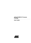
1
4:1 10-bit 1.2 Gsps MUXDAC Evaluation Kit - TSEV86101G2B .............................................................................................. User Guide Table of Contents Section 1 Introduction ........................................................................................... 1-1 1.1 1.2 Description ................................................................................................1-1 MUXDAC Evaluation Kit............................................................................1-1 Section 2 General Description .............................................................................. 2-1 2.1 2.2 2.3 MUXDAC Evaluation System....................................................................2-1 Block Diagram...........................................................................................2-1 Hardware ..................................................................................................2-2 2.3.1 Board Mechanical Characteristics ......................................................2-3 2.3.2 Board Layout Information ...................................................................2-4 2.4 Software ....................................................................................................2-5 Section 3 Getting Started...................................................................................... 3-1 3.1 Software Installation..................................................................................3-1 3.1.1 Platform Requirements.......................................................................3-1 3.1.2 Installation Procedure.........................................................................3-1 3.2 Hardware Setup ........................................................................................3-8 3.2.1 Power Supply Requirements ..............................................................3-8 3.2.2 HF Clock.............................................................................................3-8 3.2.3 Analog Output.....................................................................................3-8 3.2.4 Option Selections ...............................................................................3-9 3.2.5 Startup Procedure (Stand-alone Mode)............................................3-10 3.2.6 Startup Procedure (PC Driven Mode)...............................................3-10 3.2.7 Diode Temperature Monitoring.........................................................3-10 3.2.8 Frequency Fcw .................................................................................3-11 3.2.9 Troubleshooting................................................................................3-11 Section 4 Operating Modes .................................................................................. 4-1 4.1 4.2 Overview ...................................................................................................4-1 Pattern Management ................................................................................4-2 4.2.1 4.3 Typical Operation Flow.......................................................................4-2 Error Messages.........................................................................................4-4 MUXDAC Evaluation Kit - TSEV86101G2B User Guide i 2194B–BDC–04/04 Table of Contents Section 5 Ordering Information............................................................................. 5-1 Section 6 Appendix I: Pattern Formats ................................................................. 6-1 6.1 6.2 Pattern Structure .......................................................................................6-1 Vector Structure ........................................................................................6-1 6.2.1 First Example......................................................................................6-1 6.2.2 Second Example ................................................................................6-2 6.3 Patterns Furnished on the CD-ROM .........................................................6-2 Section 7 Appendix II: Pattern Generator Software.................................................................. 7-1 ii 2194B–BDC–04/04 MUXDAC Evaluation Kit - TSEV86101G2B User Guide Section 1 Introduction 1.1 Description The TSEV86101G2B Evaluation Board (EB) is a prototype board which has been designed in order to facilitate the evaluation and characterization of the TS86101G2B MUXDAC device (CI-CGA-255 cavity up packaged device) over an output band of interest of up to 300 MHz, at 600 Msps maximum conversion rate (Sampling Rate limited by the FPGA performance only). The TSEV86101G2B Evaluation Kit contains all the software and hardware necessary to setup the board and perform its characterization. The evaluation system of the TS86101G2B MUXDAC device consists in a configurable printed circuit board (the Evaluation board itself), including the soldered MUXDAC device (CI-CGA-255 package), an FPGA chip, a serial interface to a Windows95® or Windows98® computer and a user interface running on that platform. 1.2 MUXDAC Evaluation Kit The MUXDAC evaluation kit contains: 1 MUXDAC evaluation board 1 CD-ROM that contains the User Interface Installation Software, the User Manual, the Pattern Generator Software, and some pattern files. MUXDAC Evaluation Kit - TSEV86101G2B User Guide 1-1 Rev. 2194B–BDC–04/04 Section 2 General Description 2.1 MUXDAC Evaluation System The MUXDAC evaluation system consists of: A configurable printed circuit board, including a soldered MUXDAC in a CI-CGA 255 package An FPGA A serial interface to a computer running Windows® 95/98 A user interface running on the above platform 500 x 40-bit max test patterns are loaded into the FPGA and applied to the MUXDAC. 2.2 Block Diagram Figure 2-1. Block Diagram Differential Data bus 80-bit MUXDAC 10-bit Control signal onboard FPGA with integrated SRAM MUX Analog differential Output DAC Spectrum analyzer Data clock Differential LVDS DSP Clock Connection to PC (LabVIEWTM...) MUXDAC Evaluation Kit - TSEV86101G2B User Guide Differential Input Clock 2-1 Rev. 2194B–BDC–04/04 General Description 2.3 Hardware Figure 2-2. MUXDAC Printed Board Circuit Figure 2-2 show, from left to right: Serial interface connector, FPGA surrounded with termination resistors and 50Ω tracks, MUXDAC area, sampling delay rotating switch, SMA connectors for differential clock and output. From top to bottom: FPGA glue logic (Status leds, reset button, serial interface crystal, configuration EPROM), MUXDAC power connectors (4 mm plugs), FPGA and MUXDAC, clock interface (delay line with 2 programming switches, differential to single ended interface), FPGA power connectors (4 mms plugs). 2-2 2194B–BDC–04/04 MUXDAC Evaluation Kit - TSEV86101G2B User Guide General Description 2.3.1 Board Mechanical Characteristics 2.3.1.1 Board Layer Thickness Profile The board layer numbers, thickness and functions are given below, from top to bottom. Table 2-1. Board Layer Thickness Profile Layer Characteristics Layer 1 Copper Layer Copper Thickness = 35 µm AC signal Traces = 50Ω microstrip lines DC signal Traces (DIODE, CS) Layer 2 Copper Layer Copper thickness = 35 µm AGND, DGND (separate traces) Layer 3 Copper Layer Copper thickness = 35 µm AC Signal Traces = 50Ω microstrip lines (Input Data) Layer 4 Copper Layer Copper thickness = 35 µm AGND, DGND (separate traces) Layer 5 Copper Layer Copper thickness = 35 µm MUXDAC VCC, FPGA +1.5V supply Layer 6 Copper Layer Copper thickness = 35 µm Separate VEEA and VEED FPGA +2.5V and +3.3V supplies Layer 7 Copper Layer Copper thickness = 35 µm AGND, DGND (separate traces) Layer 8 Copper Layer Copper thickness = 35 µm AC signal Traces = FPGA signals Layer 9 Copper Layer Copper thickness = 35 µm AGND, DGND (separate traces) Layer 10 Copper Layer Copper thickness = 35 µm AC signal traces = 50Ω microstrip lines (MUXDAC Input Data) The TSEV86101G2B Evaluation Board is a nineteen layer PCB board made of 10 copper layers and 9 dielectric layers. The metal layers correspond respectively from top to bottom to stages of two AC signal trace planes (MUXDAC or FPGA) with one ground plane (AGND/DGND) in between. The metal layers are isolated from one to another by HTG epoxy layers. Dielectric layer thickness: Between layers 1 and 2, 9 and 10: 200 µm 350 µm for all other layers Dielectric constant: ε r = 4.1 at 1 MHz Insertion Loss: -0.01 dB/inch at 1 MHz The previously described mechanical and frequency characteristics make the board particularly suitable for device evaluation and characterization in the high frequency domain and in a wide temperature range. MUXDAC Evaluation Kit - TSEV86101G2B User Guide 2-3 2194B–BDC–04/04 General Description 2.3.1.2 Input Accesses The board inputs (which correspond to the FPGA inputs) are accessed via an RS-232 serial port (9 points pin to pin connector with the RX and TX pins not inversed). The Clock input is accessed via SMA connector. 2.3.1.3 Output Accesses The board outputs are accessed differentially via SMA connectors. 2.3.1.4 Power Supplies and Ground Accesses The MUXDAC power supplies (VEED, VEEA, VCC) are accessed via banana jacks (4 mm plugs). The FPGA power supplies (+1.5V, +2.5V, +3.3V) are accessed via banana jacks (4 mm plugs). 2.3.1.5 Function Setting Accesses The DIODE Function for die junction temperature monitoring is accessed via a 2 mm banana jack. The CS (shift select for DSP clock) function is accessed through a coding wheel. 2.3.2 Board Layout Information In order to evaluate the TS86101G2B MUXDAC device easily and efficiently, two options were explored. The first one required the use of a pattern generator, which could be a costly solution for many users. The second option was to use an FPGA, which would provide specified patterns to the MUXDAC, as well as the MUXDAC input clock. Although the later option would limit the speed range of the evaluation (the maximum frequency attainable at the output of the MUXDAC, namely 600 Msps, is limited by both the FPGA output frequency capabilities and the memory widths), it was preferred to the former option because it provided a more flexible way to characterize the MUXDAC device. Because of the use of an FPGA, additional care had to be taken with the board layout, in order to separate effectively the MUXDAC signal traces from the FPGA signal traces as well as the ground traces. The following puts forward the board layout recommendations and demonstrates how the evaluation board fulfills the many implementation constraints. 2.3.2.1 Digital Inputs/Analog Outputs The board uses 50Ω impedance microstrip lines for the digital data and clock inputs and analog outputs. The input and clock signals are routed on one layer only, without using any through-hole via. The lines connecting the FPGA to the MUXDAC are 50Ω lines. 2.3.2.2 DC Function Settings The DC signal traces are low impedance. 2.3.2.3 Power Supplies Layers 9 and 11 are dedicated to the MUXDAC and FPGA power supply traces (VCC, VEED, VEEA and +1.5V, +2.5V and +3.3V). The supply traces are routed in order to present low impedance, and are surrounded by ground planes (layers 7 and 13). The analog and digital negative power supply traces are independent, but the possibility exists to short-circuit both supplies on the top metal layer. Each incoming power supply is bypassed by a 1 µF Tantalum capacitor in parallel with a 10 nF chip capacitor. Each power supply access is decoupled by a 10 nF capacitor and a 100 pF surface mounted chip capacitors in parallel, located as close as possible to the device. Note: 2-4 2194B–BDC–04/04 The decoupling capacitors are superimposed. In this configuration, the 100 pF capacitor must be mounted first. MUXDAC Evaluation Kit - TSEV86101G2B User Guide General Description 2.4 Software The MUXDAC evaluation user interface software is a LabVIEW™ compiled graphical interface, that requires no license to run on a Windows® 95/98. Figure 2-3. MUXDAC User Interface Note: The software uses intuitive buttons and pop-up menus to send data to the MUX-DAC. MUXDAC Evaluation Kit - TSEV86101G2B User Guide 2-5 2194B–BDC–04/04 Section 3 Getting Started 3.1 Software Installation 3.1.1 Platform Requirements A PC running Windows® 95/98, with an RS-232 serial port is required. Figure 3-1. Contents of the Installation Compact Disk 3.1.2 Installation Procedure The installation is performed in 3 steps: 1. Install the Muxdac10bit 4-1 v1.0. 2. Install the NI LabVIEW™ Run Time Engine 6.0. 3. Install the NI-VISA driver. 3.1.2.1 To Install the Software on a PC 1. Install the Muxdac10bit 4-1 v1.0 1.1. Insert the CD-ROM. 1.2. Open an Explorer window. 1.3. Double-click on D:\Installer10bit 4-1\setup.exe. MUXDAC Evaluation Kit - TSEV86101G2B User Guide 3-1 Rev. 2194B–BDC–04/04 Getting Started Figure 3-2. D:\Intaller 10bit 4-1 Contents 1.4. A setup window appears (see Figure 3-3) and suggests installing the program in C:\Program Files\MuxDac\10bit 4-1: Figure 3-3. Muxdac 10bit 4-1 V1.0 Intallation Window 1.5. Click on Finish to continue the installation. 3-2 2194B–BDC–04/04 MUXDAC Evaluation Kit - TSEV86101G2B User Guide Getting Started 1.6. A window appears (see Figure 3-4) to confirm that the installation is successful. Figure 3-4. Muxdac Installation Dialog Box A directory named C:\Program Files\MuxDac\10bit 4-1 is created with an executable software (this window does not appear when installing the software). Figure 3-5. C:\Program Files\MuxDac\10bit 4-1 Contents 1.7. The MuxDac 10Bit 4-1.exe software is automatically added to the Startup Menu\Programs\MuxDac 10bit 4-1 (“Menu Demarrer\Programmes” in the French version). A window appears (see Figure 3-6) to indicate that Muxdac 10bit 4-1 executable file is installed. Figure 3-6. MuxDac 10Bit 4-1.exe Software 2. Installation of NI LabVIEW™ Run Time Engine 6.0 If LabVIEW™ is not installed on your PC, it is necessary to install this free NI LabVIEW™ software. MUXDAC Evaluation Kit - TSEV86101G2B User Guide 3-3 2194B–BDC–04/04 Getting Started 2.1. When the first step has been successfully completed, a window appears (see Figure 3-7). Install Run Time Labview Engine 6.0. Figure 3-7. 1st LabVIEW Run-Time Engine Setup Window 2.2. Click on Next to continue the installation. A window appears (see Figure 3-8) and suggests installing the program in C:\Program Files\National Instruments\ Figure 3-8. 2nd LabVIEW Run-Time Engine Setup Window 3-4 2194B–BDC–04/04 MUXDAC Evaluation Kit - TSEV86101G2B User Guide Getting Started 2.3. Click on Next to continue the installation. When the installation is finished, Figure 3-9 appears. Figure 3-9. 3rd LabVIEW Run-Time Engine Setup Window 2.4. Click on Finish to terminate the installation. 3. Installation of NI-VISA software If LabVIEW™ is not installed on your PC, it is necessary to install this free NI LabVIEW™ software. 3.1. Double-click on D:\Installer10bit 4-1\NI-VISA2.5.2\setup.exe. 3.2. Figure 3-10 appears. Click Next to continue the installation. MUXDAC Evaluation Kit - TSEV86101G2B User Guide 3-5 2194B–BDC–04/04 Getting Started Figure 3-10. 1st NI-VISA Setup Window 3.3. When the installation is finished, Figure 3-11 appears. Click on Finish . Figure 3-11. 2nd NI-VISA Setup Window 3-6 2194B–BDC–04/04 MUXDAC Evaluation Kit - TSEV86101G2B User Guide Getting Started 3.4. Figure 3-12 appears and ask you to restart your computer. Click on Yes to restart your computer. Figure 3-12. NI-VISA Installer Dialog Box 3.1.2.2 Installation Testing 1. Select the program MUXDAC 10bit 4-1 v1.0 from the Startup/Program menu or double-click on C:\Program Files\MuxDac\10bit 4-1\MuxDac 10Bit 4-1.exe. 2. Figure 3-13 will be displayed. There must be no error message and the Error display must not be highlighted. If an error is detected, the Error display is highlighted: Simply click on QUIT, and close the MUXDAC window. Figure 3-13. MUXDAC User Interface 3.1.2.3 Troubleshooting 1. Check that the C:\ hard disk is properly mounted. 2. Check that you have the right to write in the directory. 3. Check for available disk space. 4. Check that the serial COM port is free and properly configured. 5. Check that the serial COM port is exactly declared with C:\Program Files\MuxDac\10bit 4-1\MuxDac 10Bit 4-1.ini file. MUXDAC Evaluation Kit - TSEV86101G2B User Guide 3-7 2194B–BDC–04/04 Getting Started 3.2 Hardware Setup 3.2.1 Power Supply Requirements 3.2.1.1 FPGA Core: 2.5V +10/-5% (Keep core voltage as high as possible for higher speed and assume current of 1A at 1 GHz) Periphery: 3.3V ±5% DGND: 0V reference voltage The core and periphery supplies should be switched on at the same moment. 3.2.1.2 Termination Voltage 1.2V – 1.6A typ., 1.5V max (2A) 3.2.1.3 MUXDAC See Specifications on Section 2. VEEA: analog ECL voltage, -5.0V (0.4 to 0.6A) VEED: digital ECL voltage, -5.0V VCCD: digital PECL voltage, +5.0V AGND: 0V reference analog voltage DGND: 0V reference digital voltage VEEA, VEED and VCCD supplies should be switched on at the same moment (otherwise, if this is not possible, in the following order: VCCD, VEEA then VEED). AGND and DGND should be connected together. 3.2.2 HF Clock Use the HF generator with a 50Ω output. 100 to 600 MHz, -1 at +5 dBm 3.2.3 Analog Output 3-8 2194B–BDC–04/04 Use an oscilloscope and/or a spectrum analyzer with a 50Ω input. MUXDAC Evaluation Kit - TSEV86101G2B User Guide Getting Started 3.2.4 Option Selections Figure 3-14. Hardware Descripton S1: FPGA reset push button D2: Orange LED, indicating FPGA initialization phase D3: Red LED, indicating FPGA initialization errors U11: MUXDAC digital inputs delay setting (Hexadecimal coding) J10/OPT1: FPGA standalone setting (with jumper: ramp output, else zero output) J10/OPT2, 3, 4: RESERVED. Jumper must be plugged in Do Not Use: JP1: JTAG programming mode when jumper is unplugged. Used only for FPGA debugging. The jumper must be plugged in for normal operation. J9: 12-pin JTAG connector. Used only for FPGA debugging. MUXDAC Evaluation Kit - TSEV86101G2B User Guide 3-9 2194B–BDC–04/04 Getting Started 3.2.5 Startup Procedure (Stand-alone Mode) The HF Clock should be on to provide the Fcw Clock to MUXDAC through the J13 SMA connector. The MUXDAC should be started first: VEEA, VEED and VCCD supplies should be switched on at the same moment. Jumper OPT1 may be unplugged (no jumper on OPT1). When the MUXDAC is ready, FPGA can be powered on. The core 2.5V and periphery 3.3V supplies should be switched on at the same moment, the terminal voltage 1.2V must be the last FPGA supply to stabilize in order to properly activate the power-onreset circuit, and start initialization. The orange LED lights during the EPROM download phase, then turns off. No LED must light after initialization. After startup, it is recommended to reset the FPGA, to lock the internal PLL on a stable clock. It’s only after reset that the OPT1 jumper may be plugged in to switch to the default (ramp) pattern. 3.2.6 Startup Procedure (PC Driven Mode) The HF Clock should be on to provide the Fcw Clock to MUXDAC through the J13 SMA connector. MUXDAC should be started first: VEEA, VEED and VCCD supplies should be switched on at the same moment. The startup option must be set to the Zero mode for a clean startup of the MUXDAC (no jumper on OPT1). When the MUXDAC is ready, FPGA can be powered on. The core 2.5V and periphery 3.3V supplies should be switched on at the same moment, the terminal voltage 1.2V must be the last FPGA supply to stabilize in order to properly activate the power-onreset circuit, and start initialization. The orange LED lights during the EPROM download phase, then turns off. No LED must light after initialization. After startup, it is recommended to reset the FPGA, to lock the internal PLL on a stable clock. When the FPGA is ready,run the MuxDac 10Bit 4-1.exe software. 3.2.7 Diode Temperature Monitoring The DIODE Pad Temp is provided for die junction temperature monitoring. Figure 3-15. Diode Temperature Monitoring 2 mm red connector under evaluation board From MUXDAC 3-10 2194B–BDC–04/04 D16 D11 D17 D12 D18 D13 D19 D14 D20 D15 V MUXDAC Evaluation Kit - TSEV86101G2B User Guide Getting Started For a given forced current in Pad Temp, the voltage across the diode mounted transistor depends linearly on the temperature. Since the characteristic of the diode may vary from deviate device, the voltage across the diode must first be measured for a known junction temperature. The measured diode mounted transistor, Vbe, values as a function of junction temperature at I = 1 mA are given below. Figure 3-16. Junction Temperature Monitoring Vdiode versus TJ (at I = 1 mA) 2.6 2.5 2.4 Vdiode (V) 2.3 2.2 2.1 2.0 1.9 1.8 0 10 20 30 40 50 60 70 80 90 100 110 120 TJ (°C) 3.2.8 Frequency Fcw 3.2.9 Troubleshooting 3.2.9.1 Orange LED Remains Alive The frequency of HF clock can be changed without turning off the board and MUXDAC. But it is recommended that the FPGA be reset in order to lock the internal PLL on a stable clock. During reset, OPT1 jumper may be unplugged. Jumper JP1 is not plugged (FPGA in JTAG mode): plug in a jumper Bad PLL lock: power off the MUXDAC, and restart FPGA Power problem (bad 3.3V rise time): check 2.5 and 3.3V voltage Restart the 3.3V power supply, unplug and replug the 3.3V connector or, change the 3.3V power supply 3.2.9.2 Red LED Remains Alive Same as the Orange LED Check if an EPROM is properly plugged in the U4 socket MUXDAC Evaluation Kit - TSEV86101G2B User Guide 3-11 2194B–BDC–04/04 Getting Started 3.2.9.3 1.2V Supply Overloaded Weak power supply: 1.7A typ required Bad PLL lock: power off the MUXDAC, and restart FPGA Check for possible shorts 2.5V Supply Overloaded Weak power supply: 1A typ required 3.2.9.5 MUXDAC Supplies Overloaded Check for possible shorts (beware of SMT components below socket) 3.2.9.6 Permanent COM Errors Reset FPGA, Reset Software (RESET button) 3.2.9.4 Check for possible shorts Exit and restart the software Verify that MUXDAC board is connected to COM1 Verify that COM1 is configured properly (even parity, 1 stop bit, LSB first, 9600 baud, RTS, DTR signals) Test FPGA initialization (LEDs, clocks, MUXDAC signals) Reset FPGA and check MUXDAC signals, MUXDAC clock (OPT1 maybe unplugged) The RS-232 serial interface should NOT have the RX and TX pins inversed. 3.2.9.7 MUXDAC to FPGA Clock Problems Check for possible shorts (beware of conflicts between the delay line and the MUXDAC) Check inputs and outputs from the differential to the single ended converter Check the high frequency clock connections (J13 SMA) and settings (frequency, level) Check FPGA initialization (PLL locked) Note: 3-12 2194B–BDC–04/04 When restarting the user interface software, always reset the FPGA before sending a pattern. MUXDAC Evaluation Kit - TSEV86101G2B User Guide Section 4 Operating Modes 4.1 Overview The MUXDAC is intended to feed a device under test with predefined patterns, stored on the host computer, in order to observe and measure most converter performances. The evaluation system is build around an FPGA, providing an internal pattern capacity of 20 Kwords RAM, organized as 512 40-bit rows. Once loaded into the FPGA memory, test patterns are looped back indefinitely, under software control. Four 10-bit words are applied to the device under test, using differential signaling every rising edge of the FPGA fast clock. In order to ease synchronization, the differential clock for pattern sampling is regenerated within the FPGA and propagated to the MUXDAC. The software provides a graphical user interface to configure the FPGA pattern generators, store test vectors in the board memory, and control execution. Buttons and pop-up menus allow the user to easily perform: Pattern file selection Pattern memory downloading into the board pattern memory The computer interface uses a standard asynchronous serial port. The serial port is organized as a byte oriented data flow running at 9600 baud, even parity, single stop bit, positive logic signaling, LSB first. The transfer protocol makes use of the DTR and RTS lines for synchronization. The automatic configuration provides users with simple access to basic operations (pattern initialization, pattern start and stop) without any knowledge about the board or the software’s internal structure. MUXDAC Evaluation Kit - TSEV86101G2B User Guide 4-1 Rev. 2194B–BDC–04/04 Operating Modes 4.2 4.2.1 Pattern Management Test pattern generation and test pattern format are detailed in Section 6 and Section 7. Typical Operation Flow 1. Insert the MUXDAC in the socket if the MUX-DAC is not soldered ( be careful of Pin 1). Writing patterns to the board’s RAM memory is transparently handled by the user interface software (length computing, register programming, byte formatting, serial link framing), as long as the pattern format is respected. 2. Apply the HF clock to the board. 3. Power on the MUXDAC. 4. Power on the FPGA. 5. Connect appropriate test tools to the analog output (oscilloscope, spectrum analyzer, etc...). 6. Start the user interface software. Figure 4-1. MUXDAC User Interface 7. Reset the FPGA. 8. Check that no error is flagged. 9. Select a pattern. Figure 4-2. Pattern Selection 4-2 2194B–BDC–04/04 MUXDAC Evaluation Kit - TSEV86101G2B User Guide Operating Modes 9.1. Click on in the user interface Pattern file menu. The Select pattern file window pops-up. 9.2. Select a pattern file by double-click on the file name. The file name is now displayed in the pattern file box. The Nb vectors and header box indicate information about the pattern file. Figure 4-3. MUXDAC User Interface 9.3. Click on Send pattern . Wait until end of transfer file. 10. Start the pattern operation by clicking on Start keyboard. or press F4 on the 11. Stop the pattern operation by clicking on Stop keyboard. or press F5 on the By default, the path used to select a pattern file is the one defined in: C:\Program Files\MuxDac\10bit 4-1\MuxDac 10Bit 4-1.ini This default path can be changed by modifying the item PatternDir of the file MuxDac 10Bit 4-1.ini By default, there is a single pattern file which is: C:\Program Files\MuxDac\10bit 4-1\600M_264.9M_0.0dBFS.txt MUXDAC Evaluation Kit - TSEV86101G2B User Guide 4-3 2194B–BDC–04/04 Operating Modes 4.3 Error Messages Figure 4-4. Communication Problem Dialog Box Check that the evaluation board is powered ON. Check the serial interface cable. Check serial port settings (even parity, 1 stop bit, lsb first, 9600 baud, RTS, DTR signals). Reset or reinitialize FPGA (power off 2.5 and 3.3V supplies). Check the test pattern file format (if the pattern was modified manually). 4-4 2194B–BDC–04/04 MUXDAC Evaluation Kit - TSEV86101G2B User Guide Section 5 Ordering Information Part Number Package Temperature Range Screening Level Comments Please contact your local Atmel sales office TSX86101G2BGL CBGA 255 Ambient Prototype TS86101G2BCGL CBGA 255 Commercial grade 0° C < TC TJ < 90° C Standard TS86101G2BVGL CBGA 255 Industrial grade -40° C < TC TJ < 110° C Standard MUXDAC Evaluation Kit - TSEV86101G2B User Guide 5-1 Rev. 2194B–BDC–04/04 Section 6 Appendix I: Pattern Formats The pattern file must be written in a fixed format: Plain text file 512 pattern lines maximum (board maximum allowed value) 6.1 Pattern Structure As the multiplexing ratio is not a power of 2, care should be exercised to ensure a clean transition when looping back from the last vector line to the first one: For P 4x10-bit samples per analog signal period sequences, it is recommended that the pattern contains 4 x P words (=> P-1 length integer value). The pixel clock should thus be selected such that P ≤512. The minimum pattern size has been fixed to 4 vectors. Should the pattern be shorter than 4 vectors, then it must be simply repeated in order to fill at least the requested 4 vectors. The maximum pattern size is 512 lines, which is the maximum memory depth in the FPGA. 6.2 Vector Structure Vector 0: Bits Vector: 1000000000 A9............A0 1000000001 B9............B0 1000000010 C9............C0 1000000011 D9............D0 Use the binary code for pattern bits. 6.2.1 First Example Default pattern (‘ramp’, 4 first lines from PR file) File PR.dat Clock: 600 MHz Frequency: 10 MHz Vecteur 0: 0000000001 0000000010 0000000011 0000000100 Vecteur 1: 0000000101 0000000110 0000000111 0000001000 Vecteur 2: 0000001001 0000001010 0000001011 0000001100 Vecteur 3: 0000001101 0000001110 0000001111 0000010000 Etc... Note: There is no specific structure for the header. All lines preceding the line beginning by Vecteur 0: are ignored. MUXDAC Evaluation Kit - TSEV86101G2B User Guide 6-1 Rev. 2194B–BDC–04/04 Appendix I: Pattern Formats 6.2.2 Second Example Fc: 600 MHz Fout: 110.1 MHz Level: 0 dBFS Vecteur 0: 1000000000 1111010011 1101111011 0101100000 Vecteur 1: 0000000010 0100000010 1100101111 1111110100 Vecteur 2: 1001100110 0001011110 0001000111 1000111011 Vecteur 3: 1111101000 1101010001 0100101000 0000000000 Etc… This example has the format used by the pattern generator software furnished with the MUX-DAC (see Section 7). The header displays the clock rate (600 MHz), the frequency Fout of the sinewave to be generated (110.1 MHz) and the amplitude of the sinewave (0 dBFS). 6.3 Patterns Different patterns are furnished on the CD-ROM. Furnished on the The structure used is the following one: CD-ROM Directory: 600M_0.0dBFS Files: 600M_15.3M_0.0dBFS.txt 600M_264.9M_0.0dBFS.txt 600M_299.1M_0.0dBFS.txt Etc... In the above example: The name of the directory indicates that Fclock = 600 MHz and the sinewave generated is full scale (0 dBFS). The files of this directory indicate first the clock rate (600M) then the Fout Frequency (15.3M) and then the output level (0.0 dBFS). All this information is written in the header of the pattern file. Note: Patterns furnished are at a clock rate of 600 Msps. All these pattern files can be used with other sampling rates. When changing the sampling rate by a factor k, the Fout frequency is modified by the same factor k and the output level remains unchanged. If the wanted pattern is not available on the CD-ROM, it is possible to generate other patterns with the software furnished (see Section 7). 6-2 2194B–BDC–04/04 MUXDAC Evaluation Kit - TSEV86101G2B User Guide Section 7 Appendix II: Pattern Generator Software A pattern generator software is furnished on the CD-ROM. The name of the executable is muxdac10b.exe It is first necessary to copy this executable file (D:\Patterns\Pattern Generator Software\muxdac10b.exe) on your hard disk. Run this software by double-clicking on muxdac10b.exe A window appears (see Figure 7-1). Figure 7-1. Pattern Generator User Interface 1. Enter the output level (in dBFS) of the sine wave to be generated. Note: In single ended: 0 dBFS = Full scale = 1 Vpp = 0.5V peak = -6 dBV = +4 dBm In differential: 0 dBFS = Full scale = 2 Vpp = 1V peak = 0 dBV = +10 dBm 2. Enter the output frequency (in MHz). Figure 7-2. Pattern Generator User Interface MUXDAC Evaluation Kit - TSEV86101G2B User Guide 7-1 Rev. 2194B–BDC–04/04 Appendix II: Pattern Generator Software 3. Enter the Clock rate (in MHz). Figure 7-3. Pattern Generator User Interface Figure 7-4. Pattern Generator User Interface The software calculates the number of cycles NBSAMPLE x Fout/Fs. In the above example NBSAMPLE = 4 x 500, Fout = 10 and Fs = 600 so that the number of cycles is 33.3333.... The number of cycles must be an odd integer so that is truncated to 33. The new Fout value is also Fout = 33 x Fs/NBSAMPLE = 9.9 MHz When the pattern is generated, Figure 7-4 disappears. Two files are generated in the current directory: Volt_file.txt: this is the voltage values associated to each word of the pattern file. Pattern_file.txt: this is the pattern file containing 500 vectors of 4 words of 10 bits. It is recommended to rename this file in order to avoid overwriting it when generating another pattern file. To rename the file Pattern_file.txt we recommend the following structure: <Fs value>_<Fout value>_<Vout value>.txt In the above example, the file name would be 600M_9.9M_0.0dBFS.txt 7-2 2194B–BDC–04/04 MUXDAC Evaluation Kit - TSEV86101G2B User Guide Atmel Corporation 2325 Orchard Parkway San Jose, CA 95131, USA Tel: 1(408) 441-0311 Fax: 1(408) 487-2600 Regional Headquarters Europe Atmel Sarl Route des Arsenaux 41 Case Postale 80 CH-1705 Fribourg Switzerland Tel: (41) 26-426-5555 Fax: (41) 26-426-5500 Asia Room 1219 Chinachem Golden Plaza 77 Mody Road Tsimshatsui East Kowloon Hong Kong Tel: (852) 2721-9778 Fax: (852) 2722-1369 Japan 9F, Tonetsu Shinkawa Bldg. 1-24-8 Shinkawa Chuo-ku, Tokyo 104-0033 Japan Tel: (81) 3-3523-3551 Fax: (81) 3-3523-7581 Atmel Operations Memory 2325 Orchard Parkway San Jose, CA 95131, USA Tel: 1(408) 441-0311 Fax: 1(408) 436-4314 RF/Automotive Theresienstrasse 2 Postfach 3535 74025 Heilbronn, Germany Tel: (49) 71-31-67-0 Fax: (49) 71-31-67-2340 Microcontrollers 2325 Orchard Parkway San Jose, CA 95131, USA Tel: 1(408) 441-0311 Fax: 1(408) 436-4314 La Chantrerie BP 70602 44306 Nantes Cedex 3, France Tel: (33) 2-40-18-18-18 Fax: (33) 2-40-18-19-60 ASIC/ASSP/Smart Cards 1150 East Cheyenne Mtn. Blvd. Colorado Springs, CO 80906, USA Tel: 1(719) 576-3300 Fax: 1(719) 540-1759 Biometrics/Imaging/Hi-Rel MPU/ High Speed Converters/RF Datacom Avenue de Rochepleine BP 123 38521 Saint-Egreve Cedex, France Tel: (33) 4-76-58-30-00 Fax: (33) 4-76-58-34-80 Zone Industrielle 13106 Rousset Cedex, France Tel: (33) 4-42-53-60-00 Fax: (33) 4-42-53-60-01 1150 East Cheyenne Mtn. Blvd. Colorado Springs, CO 80906, USA Tel: 1(719) 576-3300 Fax: 1(719) 540-1759 Scottish Enterprise Technology Park Maxwell Building East Kilbride G75 0QR, Scotland Tel: (44) 1355-803-000 Fax: (44) 1355-242-743 Literature Requests www.atmel.com/literature Disclaimer: Atmel Corporation makes no warranty for the use of its products, other than those expressly contained in the Company’s standard warranty which is detailed in Atmel’s Terms and Conditions located on the Company’s web site. The Company assumes no responsibility for any errors which may appear in this document, reserves the right to change devices or specifications detailed herein at any time without notice, and does not make any commitment to update the information contained herein. No licenses to patents or other intellectual property of Atmel are granted by the Company in connection with the sale of Atmel products, expressly or by implication. Atmel’s products are not authorized for use as critical components in life support devices or systems. © Atmel Corporation 2004. All rights reserved. Atmel ® is a registered trademark of Atmel Corporation. Windows® is a registered trademark of Microsoft Corporation, and LabVIEW ™ is a trademark of National Semiconductors Corporation. Other terms and product names may be the trademarks of others. Printed on recycled paper. 2194B–BDC–04/04 /0M