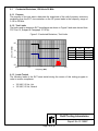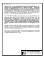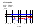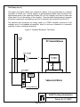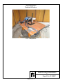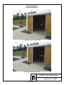
1
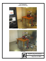
Table of Contents List of Figures ....................................................................................................................... 4 List of Tables ........................................................................................................................ 4 Certification and Signatures .................................................................................................. 5 Revision History .................................................................................................................... 6 Test Program Summary ........................................................................................................ 7 1.0 Scope ................................................................................................................... 8 2.0 Applicable Documents .......................................................................................... 8 3.0 Acronyms and Definitions ..................................................................................... 9 4.0 General Requirements ........................................................................................ 10 4.1 Test Environment ......................................................................................... 10 4.1.1 Conducted Emissions ............................................................................ 10 4.1.2 Radiated Emissions ............................................................................... 10 4.1.2.1 Formal ........................................................................................ 10 4.2 Test Instrumentation .................................................................................... 10 4.2.1 Grounding of Measuring Instrument ...................................................... 10 4.2.2 Measurement Uncertainty ..................................................................... 11 4.3 Emissions Testing ........................................................................................ 11 4.3.1 Ambient Interference Levels .................................................................. 11 4.3.2 Software ................................................................................................ 12 4.3.2.1 Stepped Scans ........................................................................... 12 4.3.3 Detector Function .................................................................................. 12 4.3.4 Measurement Frequencies .................................................................... 12 5.0 Description of Equipment Under Test ................................................................. 13 5.1 EUT Description ........................................................................................... 13 5.2 Electrical Characteristics .............................................................................. 13 5.2.1 Power Input ........................................................................................... 13 5.2.2 Highest Clock Frequency ...................................................................... 13 5.3 EUT Configuration........................................................................................ 14 5.3.1 Rationale for EUT Configuration............................................................ 14 5.3.2 Power Leads and Interconnecting Cables ............................................. 14 5.4 Modifications ................................................................................................ 14 5.5 Mode of Operation ....................................................................................... 15 5.5.1 Support Equipment ................................................................................ 15 6.0 Test Methods Performed .................................................................................... 17 6.1 Conducted Emissions, 150 kHz to 30 MHz .................................................. 18 6.1.1 Purpose ................................................................................................. 18 6.1.2 Test Limits ............................................................................................. 18 6.1.3 Leads Tested......................................................................................... 18 6.1.4 Test Setup ............................................................................................. 19 6.1.5 Test Equipment ..................................................................................... 20 6.1.6 Test Procedure ...................................................................................... 21 6.1.7 Sample Calculations .............................................................................. 22 6.1.8 Test Results .......................................................................................... 22 R Retlif Testing Laboratories Report No. R-1985P Page 2 of 36 Test Photographs .................................................................................. 23 Test Data ............................................................................................... 25 6.2 Radiated Emissions, 30 MHz to 1 GHz ........................................................ 28 6.2.1 Purpose ................................................................................................. 28 6.2.2 Test Limit ............................................................................................... 28 6.2.3 Test Setup ............................................................................................. 28 6.2.4 Test Equipment ..................................................................................... 30 6.2.5 Test Procedure ...................................................................................... 30 6.2.6 Sample Calculations .............................................................................. 31 6.2.7 Test Results .......................................................................................... 31 Test Photographs .................................................................................. 32 Test Data ............................................................................................... 35 Appendix A: FCC Rules, Verification .................................................................................. A1 Appendix B: FCC Rules, Retention of Records .................................................................. B1 Appendix C: FCC Rules, Identification / Labeling .............................................................. C1 Appendix D: FCC Rules, Information to User .................................................................... D1 Appendix E: Canadian ICES-003, Test Report ................................................................... E1 Appendix F: Canadian ICES-003, Labeling Requirements ................................................. F1 R Retlif Testing Laboratories Report No. R-1985P Page 3 of 36 List of Figures Figure 1 - General Test Setup ............................................................................................ 16 Figure 2 -Conducted Emissions, Test Limits....................................................................... 18 Figure 3 - Conducted Emissions, Test Setup...................................................................... 20 Figure 4 - Radiated Emissions, Test Limit .......................................................................... 28 Figure 5 - Radiated Emissions, Test Setup......................................................................... 29 List of Tables Table 1 - Test Methods and Results ..................................................................................... 7 Table 2 - Measurement Uncertainty .................................................................................... 11 Table 3 - Power Input.......................................................................................................... 13 Table 4 - EUT Interconnecting Cable Configurations .......................................................... 14 Table 5 - Support Equipment .............................................................................................. 15 Table 6 - Test Sequence and Results ................................................................................. 17 R Retlif Testing Laboratories Report No. R-1985P Page 4 of 36 Revision History Revisions to this document are listed below; the latest revised document supersedes all previous issues of this document: Revision - Date May 23, 2013 Pages Affected Original Release R Retlif Testing Laboratories Report No. R-1985P Page 6 of 36 Test Program Summary Report Number: Customer: Address: Test Sample: Part/Model Number: Serial Number: Manufacturer: R-1985P Z-Band, Inc. 848B N. Hanover Street Carlisle, PA 17103 Broadband Video Distribution System ZF-2400 40099 Z-Band, Inc. Test Specification: Telecommunications, CFR Title 47, Part 15 Radio Frequency Devices, Subpart B, Unintentional Radiators and Industry Canada ICES-003 Test Methods: The test methods performed on the Broadband Video Distribution System and the corresponding test results are shown in Table 1: Para. Herein FCC Paragraph 6.1 15.107(b) 6.2 15.109(b) Table 1 - Test Methods and Results IC Test Method Frequency Range Section Conducted Emissions, 6.1 150 kHz to 30 MHz Class A Radiated Emissions, 6.2 30 MHz to 1 GHz Class A Test Results Complied Complied NVLAP Lab Code 200815-0 All test methods listed above are included in Retlif Testing Laboratories Harleysville, Pennsylvania NVLAP Scope of Accreditation and were performed in accordance with the Retlif Testing Laboratory Quality System which is compliant with the requirements of ISO/IEC 17025 General Requirements for the Competence of Calibration and Testing Laboratories. R Retlif Testing Laboratories Report No. R-1985P Page 7 of 36 1.0 Scope This test report documents the methods used in measuring the conducted and radiated emissions produced by a Broadband Video Distribution System (EUT), Part/Model Number: ZF-2400, Serial Number: 40099, manufactured by Z-Band, Inc. of Carlisle, PA 17103. This report further serves to fully record the details of the sample tested including all interconnecting cables and support equipment. The objective of this test report is to demonstrate compliance of the Broadband Video Distribution System to the requirements for FCC Rules and Regulation Part 15, Subpart B, and Industry Canada, ICES-003 for a Class A Digital Device. 2.0 Applicable Documents The following documents form a part of this test report to the extent specified herein: RCM-001; Rev H - Retlif Testing Laboratories Calibration Manual RQM-001; Rev P - Retlif Testing Laboratories Quality Assurance Manual ANSI/NCSL 94 (R2002) Z540.1; - Calibration Laboratories and Measuring and Test Equipment General Requirements ISO/IEC 17025; 2005 - General Requirements for the Competence of Testing and Calibration Laboratories MIL-PRF-15733H - Filters, Radio Frequency Interference, General Specifications for MIL-STD-220B - Insertion Loss Measurement, Method of IEEE-Std-299; 09/15/06 - Attenuation Measurements for Enclosures, Electromagnetic Shielding for Electronic Test Purposes CFR, Title 47, Part 2 - Code of Federal Regulations, Telecommunications, Part 2 Frequency Allocations and Radio Treaty Matters; General Rules and Regulations CFR, Title 47, Part 15 - Code of Federal Regulations, Telecommunications, Part 15 Radio Frequency Devices ANSI C63.4:2003 - American National Standard, Methods of Measurement of Radio-Noise Emissions from Low-Voltage Electrical and Electronic Equipment in the Range of 9 kHz to 40 GHz CISPR 16 - Specification for Radio Disturbance and Immunity Measuring Apparatus and Methods ICES-003, Issue 5 - Interference - Causing Equipment Standard R Retlif Testing Laboratories Report No. R-1985P Page 8 of 36 3.0 Acronyms and Definitions The following acronyms may be used within this test report: AC: CE: CFR: CISPR: cm: dB: dBµV: dBµV/m: DC: EMC: EMI: EUT: FCC: GHz: Hz: ICES: ISM: kHz: LISN: mA: m: mm: mS: mΩ: MHz: OATS: RE: RF: RMS: µA: µF: µH: µV: µV/m: V/m: Ω: Alternating Current Conducted Emissions Code of Federal Regulations International Special Committee on Radio Interference Centimeters Decibel Decibels Relative to One Microvolt Decibels Relative to One Microvolt per Meter Direct Current Electromagnetic Compatibility Electromagnetic Interference Equipment Under Test Federal Communications Commission Gigahertz Hertz Interference Causing Equipment Standard Industrial, Scientific and Medical Kilohertz Line Impedance Stabilization Network Milliampere Meters Millimeters Millisecond Milliohm Megahertz Open Area Test Site Radiated Emissions Radio Frequency Root Mean Square Microampere Microfarad Microhenry Microvolt Microvolts per Meter Volts per Meter Ohm R Retlif Testing Laboratories Report No. R-1985P Page 9 of 36 4.0 General Requirements 4.1 Test Environment All testing was performed at the Retlif Testing Laboratories Harleysville, Pennsylvania NIST/NVLAP accredited facility. All testing was performed according to each methods individual requirement. Each test method outlined herein describes the individual environment in which testing was performed. All radiated emissions testing was performed on an FCC listed open area test site (OATS). 4.1.1 Conducted Emissions All conducted emissions testing described herein was performed on a conducting ground plane. The conducting ground plane for measuring AC power line conducted emissions consisted of a floor-earth grounded conducting surface. The conducting surface extended at least 0.5 m beyond the vertical projection (footprint) of the EUT. The ground plane was covered by insulating material 1 mm thick. 4.1.2 Radiated Emissions 4.1.2.1 Formal Formal radiated emissions testing was performed on an OATS. The test site was covered with a conducting ground plane. The equipment under test was placed in an RF transparent enclosure, on top of an 80 cm high non-metallic table which was mounted to the flush mounted, metallic turntable. The test site met the test site attenuation requirements specified in ANSI C63.4. 4.2 Test Instrumentation A listing of all test instrumentation utilized is contained within each applicable test method. These listings indicate the model, manufacturer, frequency range, last calibration date and calibration due date of all instrumentation utilized. All instrumentation utilized was calibrated prior to use in accordance with the procedures set forth in Retlif Testing Laboratories standard manuals RCM-001 and RQM-001 which are in accordance with the requirements of ANSI/NCSL Z-540.1. 4.2.1 Grounding of Measuring Instrument Interference measuring instruments were physically grounded with only one connection. When an antenna was used, the measuring instrument was connected to ground with only the power ground cord (green wire). R Retlif Testing Laboratories Report No. R-1985P Page 10 of 36 General Requirements (con’t) 4.2.2 Measurement Uncertainty In accordance with ISO/IEC 17025, Retlif Testing Laboratories has produced an estimate of the uncertainty of its measurements using accepted methods of analysis, through the production and application of suitable uncertainty of measurement procedures. For emissions testing, measurement uncertainty has been calculated in order to provide a confidence level of 95% (K=2.0). The results of these calculations are shown in the table below: Test Method Conducted Emissions Radiated Emissions 4.3 Table 2 - Measurement Uncertainty Confidence Probability K Level Distribution 95 % Normal 2.00 95 % Normal 2.00 Expanded Uncertainty 3.72 dB 6.10 dB Emissions Testing 4.3.1 Ambient Interference Levels Ambient interference levels were at least 6 dB below the specified limit for conducted emissions. For radiated emissions, the ambient levels were verified. If the ambient was within 6 dB of the specified limit, the following procedure was performed: 1. 2. The device was pre-screened in a shielded enclosure to determine its spectral content. While measuring on an OATS, the ambient interference level was measured with the EUT powered off. This scan was compared to the scan taken with the EUT powered on. Obvious ambient emissions were omitted and all emissions found to be emanating from the EUT were maximized and measured. Any emissions that were questionable were measured using a reduced bandwidth to determine if it was an ambient or if it was an emission generated from the EUT. R Retlif Testing Laboratories Report No. R-1985P Page 11 of 36 General Requirements (con’t) 4.3.2 Software 4.3.2.1 Stepped Scans EMI Measurement Software, ES-K1 Version 1-6 SP1, manufactured by Rohde and Schwarz of Munich, Germany was utilized for conducted emissions testing. This software directs the Rohde & Schwarz EMI Receiver sweep start and stop frequencies, step size, dwell time, bandwidths and detector functions. The software integrates antenna factors, cable losses, and amplifier factors (when applicable), and presents the resultant measurements in graphical format and includes the specified test limits. Software was validated prior to test by means of the pretest measurement system verifications. No Software was utilized during the course of the radiated emissions testing. 4.3.3 Detector Function For the conducted emissions testing described herein a Peak, Quasi-Peak and Average detector function was utilized as specified in CISPR 16. For the radiated emissions testing described herein a Peak and Quasi-Peak detector function was utilized as specified in CISPR 16. 4.3.4 Measurement Frequencies The entire frequency range for each applicable test method was scanned. All frequencies with emissions within 20 dB of the specified limit were recorded. R Retlif Testing Laboratories Report No. R-1985P Page 12 of 36 5.0 Description of Equipment Under Test 5.1 EUT Description The test sample was a Broadband Video Distribution System, Part/Model Number: ZF2400, Serial Number: 40099. It measured 48.30 cm wide by 30.60 cm deep by 8.90 cm high, and weighed 3.0 kg. The Broadband Video Distribution System is designed to distribute the entire spectrum of RF Video (5 MHz to 860 MHz) over a TIA/EIA 568 compliant category 6 or 7 twisted pair cabling infrastructure. A TIA/EIA 568 compliant category 5e infrastructure can also be utilized for 5 MHz to 150 MHz distribution. The Broadband Video Distribution System is rack mounted in the MDF and IDF with the port count combination necessary to address the video drops served by each specific MDF/IDF. Video is distributed throughout the facility or facilities via the “CATV IN” port of the first Broadband Video Distribution System, designed as the “master” unit. The Broadband Video Distribution System was manufactured by Z-Band, Inc. of Carlisle, PA 17103. The EUT contained the following firmware: 5.2 Revision 27 Electrical Characteristics 5.2.1 Power Input Table 3 details the electrical power requirements of all EUT components: Description EUT Table 3 - Power Input Input Frequency Voltage 120 VAC 60 Hz Current Phase <2A Single 5.2.2 Highest Clock Frequency The highest clock frequency generated or used by the EUT was 16 MHz. R Retlif Testing Laboratories Report No. R-1985P Page 13 of 36 Description of Equipment Under Test (con’t) 5.3 EUT Configuration For all test methods, the EUT was configured as shown in Figure 1 - General Test Setup. 5.3.1 Rationale for EUT Configuration The EUT was set up in accordance with CISPR 22. The EUT was selected by the manufacturer and presented to Retlif for testing. All components and features were contained within the model which will be marketed. The cabling utilized was representative of that which would be used in actual use and/or installation. 5.3.2 Power Leads and Interconnecting Cables All power and interconnecting cables, including cable length, routing and type were as specified in Table 4. Two (2) cable sets were used for Radiated Emissions and Conducted Emissions. All cables were of the same construction and termination, but had different lengths. Table 4 - EUT Interconnecting Cable Configurations Description EUT Port EUT F Connector EUT (12) RJ45 EUT (12) RJ45 Cable Length Signal Cable Description (Meters) Description ~100 (RE) / Broadband RF Shielded / RG6 Quad ~ 4 (CE) ~30 (RE) / Shielded / CAT 6A Broadband RF ~4 (CE) (10GX64) - Foiled Shielded / CAT 6A ~30 (RE) / Broadband RF (10GX32) ~4 (CE) Routed To CATV IN (EUT) Balun HZ-5002-1 Balun HZ-5002-1 The following ports of the EUT were unpopulated during the course of this testing program: Quantity of 24 RJ45 Ports Coax ports on rear of EUT case, Terminated into 75 ohm RF terminators, 10 inbound and 8 outbound. 5.4 Modifications No modifications were made to the EUT during the course of this testing program in order to demonstrate compliance with the specified requirements. R Retlif Testing Laboratories Report No. R-1985P Page 14 of 36 Description of Equipment Under Test (con’t) 5.5 Mode of Operation During the performance of all testing specified herein, the EUT was operating at a low frequency (Ch. 4, 69 MHz ± 3 MHz), an intermediate frequency (Ch. 68, 489 MHz, ± 3 MHz) and a digital Hi frequency (Ch. 134, 855 MHz, ± 3 MHz), and transmitting broadband RF through CATV IN coaxial port. The applied signal was conditioned by the Broadband Video Distribution System and distributed through 24 RJ45 ports through CAT 6A cable to HZ5002-1 Baluns (I/Port/Cable). 5.5.1 Support Equipment All equipment that was utilized to achieve the EUT operating state specified in Paragraph 5.5 is listed in Table 5: Description Digital Modulator (2) Digital Modulator (24) Balun Table 5 - Support Equipment Manufacturer Part Number Drake N/A Zee Vee N/A Z-Band HZ-5002-1 R Model Number DSE 24 ZV-170 N/A Retlif Testing Laboratories Report No. R-1985P Page 15 of 36 Figure 1 - General Test Setup R Retlif Testing Laboratories Report No. R-1985P Page 16 of 36 6.0 Test Methods Performed The following test methods were performed on the Broadband Video Distribution System, Part/Model Number: ZF-2400, Serial Number: 40099, in accordance with the requirements of ANSI C63.4 and FCC Rules and Regulation Part 15, Subpart B, and Industry Canada, ICES-003 Class A. All testing documented herein was performed in the sequence shown in Table 6. Table 6 - Test Sequence and Results Testing Dates FCC Paragraph IC Section May 20, 2013 15.107(b) 6.1 May 20, 2013 15.109(b) 6.2 Test Method Conducted Emissions, Class A Radiated Emissions, Class A Frequency Range Results 150 kHz to 30 MHz Complied 30 MHz to 1 GHz Complied See individual test methods contained in Paragraphs 6.1 and 6.2 of this test report for a full description of the test procedures utilized and the results obtained. R Retlif Testing Laboratories Report No. R-1985P Page 17 of 36 6.1 Conducted Emissions, 150 kHz to 30 MHz 6.1.1 Purpose The purpose of this test was to determine the magnitude of the radio frequency emissions emanating from the EUT via conduction on the AC power leads in the frequency range of 0.150 to 30 MHz. 6.1.2 Test Limits The limits used to determine EUT compliance are shown in Figure 2 and were derived from FCC Part 15, Subpart B, Paragraph 15.107(b): Figure 2 -Conducted Emissions, Test Limits Limit Level (dBµV) 80 150 kHz Average Limit 66 dBµV Quasi-peak Limit 79 dBµV 500 kHz 66 dBµV 79 dBµV 500 kHz 60 dBµV 73 dBµV 30 MHz 60 dBµV 73 dBµV Frequency 70 60 ® 50 0.01 0.1 1 10 100 Frequency (MHz) 6.1.3 Leads Tested The following leads of the EUT were tested during the course of this testing program in order to ensure compliance: 120 VAC, 60 Hz, Hot 120 VAC, 60 Hz, Neutral R Retlif Testing Laboratories Report No. R-1985P Page 18 of 36 6.1.4 Test Setup The EUT and associated cabling, configured as detailed in Paragraph 5.0 herein, was placed on a 0.8 m high non-conductive test stand above the horizontal ground plane. The horizontal ground plane extended at least 0.5 m beyond the boundary of the equipment under test, and had a minimum size of 2.0 m x 2.0 m. The 0.8 m test stand was positioned such that the distance between the EUT and the vertical reference plane was 0.4 m. All EUT components were located at least 0.8 m from all other metal surfaces. The ground plane was connected to the reference earth terminal of the LISN (V-network) with a conductor as short as possible. The LISN was located so that its closest surface was no less than 0.8 m from the nearest boundary of the equipment under test. Each current carrying conductor of the EUT’s power cord was then connected to a 50 ohm/50 µH LISN. The LISNs were mounted to the ground plane in a position that produced a minimum distance of 0.8 m between the EUT and the LISNs. Power cord length in excess of 1.0 m was folded to and forth to form a bundle in the approximate center of the cable not exceeding 0.4 m until the overall cable length was equal to 1.0 m. Earth connections, where required for safety purposes, were connected to the reference “earth” point of the LISN. Where not otherwise provided or specified by the manufacturer, they were 1 m long and run parallel to the mains connection at a distance of not more than 0.1 m. The power and signal cables were oriented in relation to the ground plane in a manner equivalent to actual use. Excess lengths of interconnecting cables were bundled at the approximate center of the cable with bundles 30 to 40 cm in length, such that no cable was closer than 0.4 m to the horizontal ground plane. The RF port of the LISN was connected to the test receiver by means of 50 Ohm coaxial cable through a transient limiting device. The RF ports of LISNs installed in power leads not under test were terminated in 50 Ohms. R Retlif Testing Laboratories Report No. R-1985P Page 19 of 36 Figure 3 - Conducted Emissions, Test Setup 6.1.5 Test Equipment The details of the test equipment utilized during the performance of this test method are shown below: EN Manufacturer Description Range Model No. Cal Date Due Date 713 ROHDE & SCHWARZ EMI TEST RECEIVER 20 Hz - 26.5 GHz ESIB26 6/8/2012 6/30/2013 8194 SOLAR ELECTRONICS LINE IMPEDANCE STABILIZATION NETWORK 10 kHz - 30 MHz 8028-50-TS-24-B 1/14/2013 1/31/2014 8195 SOLAR ELECTRONICS LINE IMPEDANCE STABILIZATION NETWORK 10 kHz - 30 MHz 8028-50-TS-24-B 1/14/2013 1/31/2014 8276 ELGAR TRANSFORMER 2.5-13 No Calibration Required 8496 NARDA MED POWER ATTENUATOR 768-10 6/4/2012 DC-11GHZ / 20W R 6/30/2013 Retlif Testing Laboratories Report No. R-1985P Page 20 of 36 6.1.6 Test Procedure With the test instrumentation and the EUT configured as stated above, the following steps were performed in accordance with ANSI C63.4: 1. 2. 3. 4. 5. 6. 7. 8. 9. The EUT was operated as detailed in Paragraph 5.5 herein. The measurement system was configured to measure the emissions on the first lead under test in the frequency range of 150 kHz to 30 MHz, utilizing a peak detector function. The peak data obtained in Step 2 was then compared to the specified Quasi-Peak and average limits. If the peak data obtained in Step 2 was found to be in compliance with the average limit, then this lead of the test sample was found to comply and the next lead under test was configured for testing beginning at step 2. If the peak data obtained in Step 2 was found to be in compliance with the QuasiPeak limit but not the average limit, the emissions exceeding the average limit were measured utilizing a CISPR compliant receiver with an average detector. If the average data obtained in Step 5 complied with the average limit then this lead of the test sample was found to comply and the next lead under test was configured for testing beginning at Step 2. If the peak data obtained in Step 2 did not comply with the both specified QuasiPeak and average limits the emissions exceeding the specified limits were measured utilizing a CISPR compliant receiver with both Quasi-Peak and average detectors. The obtained Quasi-Peak data was then compared to the specified Quasi-Peak limit, and the average data was compared to the average limit. If the obtained data was found to be in compliance with specified limits, then this lead of the test sample was found to comply. Steps 1 through 8 were repeated for each remaining lead of the EUT. R Retlif Testing Laboratories Report No. R-1985P Page 21 of 36 6.1.7 Sample Calculations Shown below is a sample showing calculations used, either manually or under software control, to derive the final corrected reading. RC = MR + CIL + AIL Where: RC = Corrected Reading in dBµV MR = Meter Reading in dBµV CIL = Insertion Loss of Cable in dB AIL = Insertion Loss of Attenuator in dB Example: Mr = 43.5 dBµV CIL = 0.15 dB AIL = 10.2 dB RC = 43.5 + 0.15 + 10.2 = 53.85 dBµV 6.1.8 Test Results The EUT was found to comply with the requirements specified for this method. No emissions which exceeded the limits specified in Part 15, Subpart B or Industry Canada, ICES-003 for a Class A digital device, were observed. See the following test photographs and test data for a full presentation of the results obtained. R Retlif Testing Laboratories Report No. R-1985P Page 22 of 36 Test Photographs Conducted Emissions R Retlif Testing Laboratories Report No. R-1985P Page 23 of 36 Test Photographs Conducted Emissions EUT Configuration Test Setup R Retlif Testing Laboratories Report No. R-1985P Page 24 of 36 FCC Part 15, Subpart B, Class A, Conducted Emissions Power Leads 150 kHz to 30 MHz Test Data R Retlif Testing Laboratories Report No. R-1985P Page 25 of 36 Retlif Testing Laboratories, R-1578P Conducted Emissions, 150 kHz to 30 MHz Customer: Test Sample: Part/Model Number: Test Specification: Mode of Operation: Technician/Date: Lead Tested: Z-Band, Inc. Broadband Video Distribution System ZF-2400 FCC Part 15 Subpart B Transmitting 3 Channel Frequencies B. Reitz / 05/20/2013 115 VAC, 60 Hz, Hot Level [dBµV] 100 80 60 40 20 0 -20 150k 300k 500k 1M 2M Frequency [Hz] 3M Page 26 of 36 5M 7M 10M 30M Retlif Testing Laboratories, R-1578P Conducted Emissions, 150 kHz to 30 MHz Customer: Test Sample: Part/Model Number: Test Specification: Mode of Operation: Technician/Date: Lead Tested: Z-Band, Inc. Broadband Video Distribution System ZF-2400 FCC Part 15 Subpart B Transmitting 3 Channel Frequencies B. Reitz / 05/20/2013 115 VAC, 60 Hz, Neutral Level [dBµV] 100 80 60 40 20 0 -20 150k 300k 500k 1M 2M Frequency [Hz] 3M Page 27 of 36 5M 7M 10M 30M 6.2 Radiated Emissions, 30 MHz to 1 GHz 6.2.1 Purpose The purpose of this test was to determine the magnitude of the radio frequency emissions emanating from the EUT via radiation from the enclosure and connected cabling in the frequency range of 30 MHz to 1 GHz. 6.2.2 Test Limit The field strength of radiated emissions from a Class A digital device, as determined at a distance of 10 meters, did not exceed the limits shown in Figure 4. These limits were used to determine EUT compliance and were derived from FCC Part 15, Subpart B, Paragraph 15.109(b). Figure 4 - Radiated Emissions, Test Limit Limit Level (µV/m) 280 230 180 130 Frequency Limit Level 30 MHz 90 µV/m 88 MHz 90 µV/m 88 MHz 150 µV/m 216 MHz 150 µV/m 216 MHz 210 µV/m 960 MHz 210 µV/m 960 MHz 300 µV/m 1 GHz 300 µV/m ® 80 10 1000 Frequency (MHz) 6.2.3 Test Setup The EUT and associated cabling, configured as detailed in Paragraph 5.0 herein was placed on a 0.8 m non-conductive test stand on the flush mounted turntable. The turntable positions were relative to the EUT as follows: When facing the EUT the front is at 0o, the rear is at 180o and the left side is at 270o. The test stand was situated such that the nearest part of the boundary of the EUT was located 10.0 m from the measuring antenna. The AC power cables were routed to the AC mains outlet located on top of the turntable. Excess power cable length was left on the surface of the turntable. Earth connections, where required for safety purposes, were connected to a ground reference point on the turntable. Where not otherwise provided or specified by the manufacturer, they were 1.0 m long and run parallel to the mains connection at a distance of not more than 0.1 m. R Retlif Testing Laboratories Report No. R-1985P Page 28 of 36 Test Setup (con’t.) The power and signal cables were oriented in relation to the ground plane in a manner equivalent to actual use. Excess lengths of interconnecting cables were bundled at the approximate center of the cable with bundles 30 to 40 cm in length, such that no cable was closer than 0.4 m to the surface of the turntable. Care was taken during testing to relocate all system components and cabling in an effort to maximize the emissions from the EUT. The antenna was connected via coaxial cable to a CISPR compliant receiver for final readings and to a broadband pre-amplifier, which in turn was connected to a spectrum analyzer in order to maximize emissions. Figure 5 - Radiated Emissions, Test Setup R Retlif Testing Laboratories Report No. R-1985P Page 29 of 36 6.2.4 Test Equipment The details of the test equipment utilized during the performance of this test method are shown below: EN Manufacturer Description Range Model No. Cal Date Due Date 8076 AGILENT / HP SPECTRUM ANALYZER 100 Hz - 1.5 GHz 8568B 8/7/2012 8/31/2013 8077 AGILENT / HP SPECTRUM ANALYZER 85662A 8/7/2012 8/31/2013 8080 ROHDE & SCHWARZ EMI TEST RECEIVER 20-1300 MHz 354-3000.56ESVP 5/9/2013 5/31/2014 8300C UNKNOWN 3/10 METER CABLE 3/10 METER 3 METER CABLE 8/15/2012 8/31/2013 8411 SONOMA INSTRUMENT PRE-AMPLIFIER 9 kHz - 1 GHz 310N 8/9/2012 8/31/2013 8433 ETS LINDGREN BICONILOG 20 - 6000 MHz 3142D 8/2/2012 2/28/2014 6.2.5 Test Procedure With the test instrumentation and the EUT configured as stated above, the following steps were performed in accordance with ANSI C63.4: 1. 2. 3. 4. 5. 6. 7. a. b. c. 8. 9. The EUT was operated as detailed in Paragraph 5.5 herein. The spectrum analyzer was configured to display the frequency range of test. With the test antenna both horizontally and vertically polarized, the EUT cabling was relocated in order to maximize the radiated emissions. The operating mode of the EUT was varied in order to determine the operating mode which produced maximum radiated emissions with respect to the limit. The EUT configuration which produced maximum radiated emissions with respect to the limit was maintained for the duration of testing. The frequency of test was scanned to determine the frequency of all emissions from the EUT. At each frequency upon which an emission was determined to be from the EUT the following steps were performed in order to further maximize the observed emissions: The test antenna height was varied from 1.0 m to 4.0 m. The test antenna polarization was varied from vertical to horizontal. The EUT was rotated 360° about its vertical axis. The RF cable from the test antenna was connected to the CISPR compliant receiver. For all emissions found to be within 20 dB of the specified limit, the following was recorded: a. Frequency of emission. b. Quasi-Peak detector receiver meter reading. c. Correction factor consisting of antenna factor and cable loss. d. Test antenna height and polarization. e. Turntable position. R Retlif Testing Laboratories Report No. R-1985P Page 30 of 36 6.2.6 Sample Calculations Shown below is a sample showing calculations used, either manually or under software control, to derive the final corrected reading. RC = MR + CIL + AF - GP Where: RC = Corrected Reading in dBµV/M MR = Meter Reading in dBµV CIL = Insertion Loss of Cable in dB AF = Antenna Factor in dB GP = Gain of Pre-Amplifier in dB Example: MR = 25.3 dBµV CIL = 3.6 dB AF = 12.4dB GP = 20.5 dB RC = 25.3 + 3.6 + 12.4 – 20.5 = 20.8 dBµV/M 6.2.7 Test Results The EUT was found to comply with the requirements specified for this method. No emissions which exceeded the limits specified in Part 15, Subpart B or Industry Canada, ICES-003 for a Class A digital device were observed. See the following test photographs and test data for a full presentation of the results obtained. R Retlif Testing Laboratories Report No. R-1985P Page 31 of 36 Test Photographs Radiated Emissions R Retlif Testing Laboratories Report No. R-1985P Page 32 of 36 Test Photographs Radiated Emissions EUT Configuration R Retlif Testing Laboratories Report No. R-1985P Page 33 of 36 Test Photographs Radiated Emissions Horizontal Antenna Polarization Vertical Antenna Polarization R Retlif Testing Laboratories Report No. R-1985P Page 34 of 36 FCC Part 15, Subpart B, Class A Radiated Emissions, 30 MHz to 1 GHz Paragraph 15.109(b) Test Data R Retlif Testing Laboratories Report No. R-1985P Page 35 of 36 FCC Part 15, Subpart B, Class A Radiated Emissions, 30 MHz to 1 GHz, Paragraph 15.109(b) Z-Band, Inc Customer: Job No.: R-1985P Broadband video Distribution System Test Sample: ZF-2400 Part/Model No.: Serial No.: 40099 Operating Mode: Transmitting 3 Channel Frequencies B. Reitz Technician: Date: 5/20/13 All readings extrapolated to 10 M via 1/D Notes: Test Distance: 3 Meters Temp: 20C Relative Humidity: 57% Detector Function: Quasi-Peak below 1 GHz Antenna EUT Meter Correction Corrected 10 Meter Converted 10 M Frequency Position Orientation Reading Factor Reading Equivalent Reading Limit Test Method: MHz (V/H) / Meters Degrees dBuV dB dBuV/m dBuV uV/m 30 67.378 67.378 V/ 1.18 H/ 3.00 213.6 131.7 16.8 18.6 9.18 9.18 25.98 27.78 15.53 17.33 5.98 7.35 349.306 349.306 V/ 1.47 H/ 1.18 181.5 312.8 16.2 15.8 19.21 19.21 35.41 35.01 24.96 24.56 17.70 16.9 353.213 353.213 V/ 1.00 H/ 1.00 272.7 259.1 14.2 19.3 19.21 19.21 33.41 38.51 22.96 28.06 14.06 25.29 487.023 487.023 V/ 1.40 H/ 2.25 170.5 217.9 20.5 12.4 22.98 22.98 43.48 35.38 33.03 24.93 44.82 17.64 800.897 800.897 V/ 1.63 H/ 1.17 244.7 140.2 17.6 21.0 28.84 28.84 46.44 49.84 35.99 39.39 63.02 93.22 853.904 853.904 V/ 2.72 H/ 1.59 200.6 148.1 20.4 23.5 28.75 28.75 49.15 52.25 38.7 41.8 86.1 123.03 88 88 216 216 960 960 1,000 uV/m 90 | | | | | 90 150 | 150 210 | | 150 210 | | | | | | | | | | | | | | 210 300 | | 300 The frequency range was scanned from 30 MHz to 1 GHz. The emissions observed from the EUT do not exceed the specified limits. Emissions not recorded were more than 20dB under the specified limit. R Retlif Testing Laboratories Report No. R-1985P Page 36 of 36 Appendix A: FCC Rules, Verification R Retlif Testing Laboratories Report No. R-1985P Page A1 of A3 Appendix A Sec. 2.902 Verification. (a) Verification is a procedure where the manufacturer makes measurements or takes the necessary steps to insure that the equipment complies with the appropriate technical standards. Submittal of a sample unit or representative data to the Commission demonstrating compliance is not required unless specifically requested by the Commission pursuant to Sec. 2.957, of this part. (b) Verification attaches to all items subsequently marketed by the manufacturer or importer which is identical as defined in Sec. 2.908 to the sample tested and found acceptable by the manufacturer. Sec. 2.908 Identical defined. As used in this subpart, the term identical means identical within the variation that can be expected to arise as a result of quantity production techniques. Sec. 2.909 Responsible Party The following parties are responsible for the compliance of radio frequency equipment with the applicable standards: (b) In the case of equipment subject to authorization under the verification procedure, the manufacturer or, in the case of imported equipment, the importer. If subsequent to manufacture and importation, the radio frequency equipment is modified by any party not working under the authority of the responsible party, the party performing the modification becomes the new responsible party. (d) If, because of modifications performed subsequent to authorization, a new party becomes responsible for ensuring that a product complies with the technical standards and the new party does not obtain a new equipment authorization, the equipment shall be labeled, following the specifications in Sec. 2.925(d), with the following: This product has been modified by [insert name, address and telephone number of the party performing the modifications]. R Retlif Testing Laboratories Report No. R-1985P Page A2 of A3 Appendix A (continued) Sec. 2.952 Limitation on verification. (a) Verification signifies that the manufacturer or importer has determined that the equipment has been shown to be capable of compliance with the applicable technical standards if no unauthorized change is made in the equipment and if the equipment is properly maintained and operated. Compliance with these standards shall not be construed to be a finding by the manufacturer or importer with respect to matters not encompassed by the Commission's rules. (b) Verification of the equipment by the manufacturer or importer is effective until a termination date is otherwise established by the Commission. (c) No person shall, in any advertising matter, brochure, etc., use or make reference to a verification in a deceptive or misleading manner or convey the impression that such verification reflects more than a determination by the manufacturer or importer that the device or product has been shown to be capable of compliance with the applicable technical standards of the Commission's rules. Sec. 2.953 Responsibility for compliance. (a) In verifying compliance, the responsible party, as defined in Sec. 2.909 warrants that each unit of equipment marketed under the verification procedure will be identical to the unit tested and found acceptable with the standards and that the records maintained by the responsible party continue to reflect the equipment being produced under such verification within the variation that can be expected due to quantity production and testing on a statistical basis. (b) The importer of equipment subject to verification may upon receiving a written statement from the manufacturer that the equipment complies with the appropriate technical standards rely on the manufacturer or independent testing agency to verify compliance. The test records required by Sec. 2.955 however should be in the English language and made available to the Commission upon a reasonable request, in accordance with Sec. 2.956. (c) In the case of transfer of control of equipment, as in the case of sale or merger of the grantee, the new manufacturer or importer shall bear the responsibility of continued compliance of the equipment. (d) Verified equipment shall be reverified if any modification or change adversely affects the emanation characteristics of the modified equipment. The party designated in Sec. 2.909 bears responsibility for continued compliance of subsequently produced equipment. R Retlif Testing Laboratories Report No. R-1985P Page A3 of A3 Appendix B: FCC Rules, Retention of Records R Retlif Testing Laboratories Report No. R-1985P Page B1 of B3 Appendix B Sec. 2.955 Retention of Records (a) For each equipment subject to verification, the responsible party, as shown in Sec. 2.909 shall maintain the records listed as follows: (1) A record of the original design drawings and specifications and all changes that have been made that may affect compliance with the requirements of Sec. 2.953. (2) A record of the procedures used for production inspection and testing (if tests were performed) to insure the conformance required by Sec. 2.953. (Statistical production line emission testing is not required.) (3) A record of the measurements made on an appropriate test site that demonstrates compliance with the applicable regulations in this chapter. The record shall: (i) (ii) (iii) (iv) (v) (vi) (vii) Indicate the actual date all testing was performed; State the name of the test laboratory, company, or individual performing the verification testing. The Commission may request additional information regarding the test site, the test equipment or the qualifications of the company or individual performing the verification tests; Contain a description of how the device was actually tested, identifying the measurement procedure and test equipment that was used; Contains a description of the equipment under test (EUT) and support equipment connected to, or installed within, the EUT; Identify the EUT and support equipment by trade name and model number and if appropriate, by FCC Identifier and serial number; Indicates the types and lengths of connecting cables used and how they were arranged or moved during testing; Contain at least two drawings or photographs showing the test set-up for the highest line conducted emission and showing the test set-up for the highest radiated emission. These drawings or photographs must show enough detail to confirm other information contained in the test report. Any photographs used must be focused originals without glare or dark spots and must clearly show the test configuration used; R Retlif Testing Laboratories Report No. R-1985P Page B2 of B3 Appendix B (continued) (viii) (ix) (x) List all modifications, if any, made to the EUT by the testing company or individual to achieve compliance with the regulations in this chapter; Include all of the data required to show compliance with the appropriate regulations in this chapter; and Contain, on the test report, the signature of the individual responsible for testing the product along with the name and signature of an official of the responsible party, as designated in Sec. 2.909. (4) For equipment subject to the provisions in part 15 of this chapter, the records shall indicate if the equipment was verified pursuant to the transition provisions contained in Sec. 15.37 of this chapter. (b) The records listed in paragraph (a) of this section shall be retained for two years after the manufacture of said equipment item has been permanently discontinued, or until the conclusion of an investigation or a proceeding if the manufacturer or importer is officially notified that an investigation or any other administrative proceeding involving his equipment has been instituted. R Retlif Testing Laboratories Report No. R-1985P Page B3 of B3 Appendix C: FCC Rules, Identification / Labeling R Retlif Testing Laboratories Report No. R-1985P Page C1 of C3 Appendix C; Labeling Requirements Sec. 2.954 Identification Each device marketed shall be uniquely identified by the person responsible for marketing or importing the equipment within the United States. However, the identification shall not be of a format which could be confused with the FCC Identifier required on certified, notified or type accepted equipment. The importer or manufacturer shall maintain adequate identification records to facilitate positive identification for each verified device. 1) A record of the original design drawings and specifications and all changes that have been made that may affect compliance with the requirements of paragraph 2.953 2) A record of procedures used for production inspection and testing to insure the conformance by paragraph 2.953. 3) A record of the measurements made on an appropriate test site that demonstrates compliance with the applicable regulations in this chapter. The record shall; (i) Indicate the actual date all testing was performed; (ii) State the name of the test laboratory, company, or individual performing the verification testing. The commission may request additional information regarding the test site, the test equipment or the qualifications of the company or individual performing the verification tests; (iii) Contain a description of how the device was actually tested, identifying the measurement procedure and the test equipment that was used; (iv) Contain a description of the equipment under test (EUT) and support equipment connected to, or installed within the EUT; (v) Identify the EUT and support equipment by trade name and model number and, if appropriate, by FCC Identifier and serial number; (vi) Indicate the type and lengths of connecting cables used and how they were arranged or moved during testing; (vii) Contain at least two drawings or photographs showing the test setup for the highest line conducted emission and showing the test set-up for the highest radiated emission. These drawings or photographs must show enough detail to confirm other information contained in the test report. Any photographs used must be focused originals without glare or dark spots and must clearly show the test configuration; (viii) List all modifications, if any, made to the EUT by the testing company or individual to achieve compliance with the regulations in this chapter; R Retlif Testing Laboratories Report No. R-1985P Page C2 of C3 (ix) 4) Include all of the data required to show compliance with the appropriate regulations in this chapter; (x) Contain, on the test report, the signature of the individual responsible for testing the product along with the name and the signature of an official of the responsible party, as designated in paragraph 2.909. For equipment subject to the provisions in Part 15 of this chapter, the records shall indicate if the equipment was verified pursuant to the transition provisions contained in paragraph 15.37 of this chapter. (b) The records listed in paragraph (a) of this section shall be retained for two years after the manufacture of said equipment item has been permanently discontinued, or until the conclusion of an investigation or a proceeding if the manufacturer or importer is officially notified that an investigation or any other administrative proceeding involving his equipment has been instituted. Sec. 15.19 Labeling Requirements In addition to the requirements in FCC Part 2, a device subject to verification shall be labeled in accordance with FCC Part 15, Section 15.19 as follows: This device complies with Part 15 of the FCC Rules. Operation is subject to the following two conditions: This device may not cause harmful interference and This device must accept any interference received, including interference that may cause undesired operation. Where a device is constructed in two or more sections connected by wires and marketed together, the statement specified above is required to be affixed only to the main control unit. When the device is so small or for such use that it is not practicable to place the above statement on it, the information required shall be placed in a prominent location in the instruction manual or pamphlet supplied to the user or, alternatively, shall be placed on the container in which the device is marketed. However, the FCC identifier or the unique identifier, as appropriate, must be displayed on the device. R Retlif Testing Laboratories Report No. R-1985P Page C3 of C3 Appendix D: FCC Rules, Information to User R Retlif Testing Laboratories Report No. R-1985P Page D1 of D2 Appendix D Sec. 15.21 Information to User The user’s manual or instruction manual for an intentional or unintentional radiator shall caution the user that changes or modifications not expressly approved by the party responsible for compliance could void the user's authority to operate the equipment. In cases where the manual is provided only in a form other than paper, such as on a computer disk or over the Internet, the information required by this section may be included in the manual in that alternative form, provided the user can reasonably be expected to have the capability to access information in that form. Sec. 15.105 Information to the user. The following statement shall be provided to the text of the user’s manual in a prominent location: “This equipment has been tested and found to comply with the limits for a Class A digital device, pursuant to part 15 of the FCC Rules. These limits are designed to provide reasonable protection against harmful interference when the equipment is operated in a commercial environment. This equipment generates, uses, and can radiate radio frequency energy and, if not installed and used in accordance with the instruction manual, may cause harmful interference to radio communications. Operation of this equipment in a residential area is likely to cause harmful interference in which case the user will be required to correct the interference at his own expense.” For systems incorporating several digital devices, the statement shown above needs to be contained only in the instruction manual for the main control unit. In cases where the manual is provided only in a form other than paper, such as on a computer disk or over the Internet, the information required by this section may be included in the manual in that alternative form, provided the user can reasonably be expected to have the capability to access information in that form. R Retlif Testing Laboratories Report No. R-1985P Page D2 of D2 Appendix E: Canadian ICES-003, Test Report R Retlif Testing Laboratories Report No. R-1912P-2 Page E1 of E2 Appendix E ICES-003 Section 7 Test Report A test report shall be compiled providing a record of the tests and results demonstrating compliance with the ICES-003 technical requirements. The test report shall indicate the date the tests were completed, The test report shall clearly identify the Class of Limits, A or B, that the ITE was tested for compliance with, and shall clearly state which reference publication from Section 3 that was used for methods of measurement. The test report contents shall be in accordance with the reference publication used from Section 3. The test report shall be retained by the manufacturer or imported for a minimum period of five years from the date the model of ITE is first offered for sale, distributed and/or leased in Canada, and shall be made available to Industry Canada upon request. R Retlif Testing Laboratories Report No. R-1912P-2 Page E2 of E2 Appendix F: Canadian ICES-003, Labeling Requirements R Retlif Testing Laboratories Report No. R-1936P-2 Page F1 of F2 Appendix F ICES-003 Section 8 Labeling Requirements The manufacturer, importer or supplier shall meet the labeling requirements set out in this section for every ITE unit1: (i) Prior to marketing in Canada, for ITE manufactured in Canada, and; (ii) Prior to importation into Canada, for imported ITE. The presence of the label on the ITE represents the manufacturer’s or importer’s SelfDeclaration of Compliance (SDoC) to Industry Canada ICE-003. Each unit of an ITE model shall bear a label indicating the model’s compliance with ICES-003. The label shall be permanently affixed to the ITE or displayed electronically and its text must be clearly legible. When the dimension of the device is too small or it is otherwise not practical to place the label on the ITE, the label shall be placed in a prominent location in the user manual supplied with the ITE. The user manual may be in an electronic format and must be readily available. Industry Canada ICES-003 Compliance Label: CAN ICES-3 (*)/NMB-3(*) *Insert either “A” or “B” but not both to identify the applicable Class of ITE. 1 The labeling requirements apply to new models. Existing models may continue with the requirements in Issue 4 or adopt the requirements in Issue 5. R Retlif Testing Laboratories Report No. R-1936P-2 Page F2 of F2