1
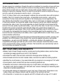
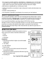
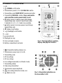
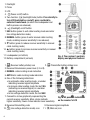
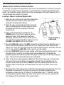
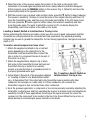
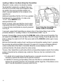
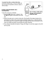
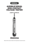
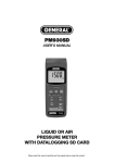
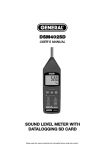
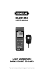
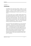
CABLE & PIPE LOCATOR
USER’S MANUAL
CL10
Please read this manual carefully and thoroughly before using this product.
TABLE OF CONTENTS
Introduction . . . . . . . . . . . . . . . . . . . . . . . . . . . . . . . . . . . . . . . . . . . . . . . . . . . . . . . . 3
Key Features & Benefits. . . . . . . . . . . . . . . . . . . . . . . . . . . . . . . . . . . . . . . . . . . . . 3 – 4
Safety Instructions . . . . . . . . . . . . . . . . . . . . . . . . . . . . . . . . . . . . . . . . . . . . . . . . . . . . 4
What’s in the Box . . . . . . . . . . . . . . . . . . . . . . . . . . . . . . . . . . . . . . . . . . . . . . . . . . . . . 4
Product Overview. . . . . . . . . . . . . . . . . . . . . . . . . . . . . . . . . . . . . . . . . . . . . . . . . . 5 – 6
Setup Instructions . . . . . . . . . . . . . . . . . . . . . . . . . . . . . . . . . . . . . . . . . . . . . . . . . . . . 7
Install Batteries . . . . . . . . . . . . . . . . . . . . . . . . . . . . . . . . . . . . . . . . . . . . . . . . 7
Install Test Leads . . . . . . . . . . . . . . . . . . . . . . . . . . . . . . . . . . . . . . . . . . . . . . . 7
Operating Instructions . . . . . . . . . . . . . . . . . . . . . . . . . . . . . . . . . . . . . . . . . . . . . 8 – 14
Single-Pole Circuit Applications . . . . . . . . . . . . . . . . . . . . . . . . . . . . . . . . 8 – 11
Locating a Cable or Line Break Behind a Wall . . . . . . . . . . . . . . . . . . 8 – 9
Locating a Socket, Switch or Junction Box or Tracing a Line . . . . . . . . . 9
Locating a Cable or Line Break Using Two Transmitters . . . . . . . . . . . . 10
Locating a Blockage in a Non-metallic Pipe . . . . . . . . . . . . . . . . . . . . . 11
Locating a Metal Water Pipe . . . . . . . . . . . . . . . . . . . . . . . . . . . . . . . . . 11
Two-Pole Circuit Applications. . . . . . . . . . . . . . . . . . . . . . . . . . . . . . . . . 12 – 14
Locating a Socket, Switch, Junction Box or Fuse or Tracing a Line. . . . 12
Identifying the Fuse or Circuit Breaker Associated with an AC Outlet . . 13
Locating a Short Circuit . . . . . . . . . . . . . . . . . . . . . . . . . . . . . . . . . . . . . 13
Increasing the Detection Range on Charged Circuits . . . . . . . . . . 13 – 14
Using the Receiver as a Voltmeter . . . . . . . . . . . . . . . . . . . . . . . . . . . . . . . . . 14
Specifications . . . . . . . . . . . . . . . . . . . . . . . . . . . . . . . . . . . . . . . . . . . . . . . . . . . . . . 15
Operating & Maintenance Instructions . . . . . . . . . . . . . . . . . . . . . . . . . . . . . . . 16 – 17
Changing Batteries. . . . . . . . . . . . . . . . . . . . . . . . . . . . . . . . . . . . . . . . . . . . . 16
Checking and Replacing the Transmitter’s Fuse . . . . . . . . . . . . . . . . . . 16 – 17
Operating & Maintenance Tips . . . . . . . . . . . . . . . . . . . . . . . . . . . . . . . . . . . . 17
Warranty Information . . . . . . . . . . . . . . . . . . . . . . . . . . . . . . . . . . . . . . . . . . . . . . . . . 18
Return for Repair Policy . . . . . . . . . . . . . . . . . . . . . . . . . . . . . . . . . . . . . . . . . . . . . . . 18
2
INTRODUCTION
On jobs ranging from installing a through-the-wall air-conditioner to renovating a house with new
wiring and plumbing, it is vital to know the locations of existing electrical cables and wires, as
well as those of metal and non-metal pipes carrying water and gas. Without access to the
building’s construction drawings, there is no way to be sure that an action as simple as driving a
nail into a wall will not produce an electric shock—or far worse.
The CL10 Cable & Pipe Locator was designed to address this serious safety issue with maximum
flexibility. The CL10 consists of two main units—a transmitter and a receiver—and a set of
accessories. The two main units work together in the following way in most applications. The
user attaches the transmitter to an existing cable or wire (or metal pipe). In response to the push
of front-panel buttons, the transmitter sends a radio-frequency current and a digital identifying
code down the cable or wire. The current generates an electric field that can be sensed by the
receiver if its nose (probe) is positioned nearby—even on the other side of a wall, floor or ceiling.
Circuits in the receiver convert the weak induced voltage into a signal strong enough to be
displayed graphically and digitally. Other circuits read the identifying code to confirm the source
of the signal. By manipulating the strength of the transmitted signal and the sensitivity of the
receiver, the user can precisely locate cables, wires or pipes behind walls or under floors, as well
as discontinuities within them.
The system is equipped with several functions and features that improve its utility, accuracy and
reliability. One is the inclusion of big, bright LCDs, visual and audible indications, and mutable
loudspeakers—as well as an LED flashlight—on both units. Another is the system’s full
compatibility with single-pole and two-pole circuits. Other examples include the ability of either
unit to measure AC/DC voltage, just like a voltmeter. The transmitter even automatically tests its
own functioning and displays the results.
KEY FEATURES AND BENEFITS
• Makes it safe to break through a wall by revealing and locating hidden cables, electrical lines,
and water/gas supply pipelines up to 6.6 ft. (2m) behind it
• Eliminates the need to find and read construction drawings before starting a job
• Detects breaks and short circuits in buried cables, electrical lines and floor-heating systems
• Identifies the circuit breaker or fuse associated with any energized or de-energized 110V outlet
• Traces branch-circuit sockets that have been accidently plastered over
• Transmitter and receiver communicate using any of eight codes; each displays readings on a
big, bright, multi-function graphic LCD. Both units also include a flashlight (for illuminating dark
areas) and a mutable beeper/buzzer.
• The transmitter displays its transmission power level (any of three levels), transmission code,
battery status, any voltages it detects, and the results of its functional self-test
• The transmitter or receiver also can operate as AC/DC voltmeter with a range of 12 to 600V
3
• The receiver has variable sensitivity, a backlit display, a loudspeaker and a 10-minute Auto
Power Off function. It can display the transmitter’s power level and transmission code, the
battery status of both units, and the amplitude of detected induced AC voltages
• Both units are compatible with one- and two-pole circuits
• Additional transmitters are available to make locating short-circuits and cable breaks more
accurate
• Includes a metal grounding rod
• The transmitter is powered by one 9V battery; the receiver by six “AAA” batteries
SAFETY INSTRUCTIONS
Prior to using the transmitter, inspect the unit, its test leads and any attached clips or probes
carefully for any signs of damage or wear. It is crucial that the instrument and its accessories
remain structurally sound. DO NOT USE the transmitter if you detect any signs of damage.
Do not exceed the transmitter’s overvoltage rating of CAT III 300V at any time.
Although it is safe to connect the transmitter directly to live circuits, use best-practice insulation
measures in accordance with industrial safety codes to avoid electric shock and harm.
When near dangerously high voltages, make measurements only under the supervision of a
qualified electrician.
WHAT’S IN THE BOX
The CL10’s transmitter, receiver and accessories come in a
black canvas pouch inside an illustrated cardboard box.
1. Pouch
2. Receiver
3. Transmitter
Accessories
4. Attachable red and black alligator clips with shrouded
banana jacks
5. “9V” battery
6. 6 “AAA” batteries
7. User’s manual
8. 5 ft. (1.5m) long red and black universal test leads with
shrouded banana plugs
9. Attachable red and black test probes with lantern-type tips
and shrouded banana jacks
10. Grounding rod
Fig. 1. How the CL10 is packaged
4
PRODUCT OVERVIEW
1. LCD
2.
(POWER on/off) button
3. Transmission power (I, II or III) LEVEL SEL. button
4. Transmitting code START/STOP transmission button
5. Transmitting CODE SEL. button. Press and hold to
enter selection mode; press briefly to exit.
6. ▼ button (press to reduce power level/change
transmitting code). Levels I, II and III and codes
F (default), E, H, D, L, C, O and A are available.
7. ▲ button (press to increase power level/change
transmitting code)
8.
(Mute) on/off button
9.
(Flashlight) on/off button
10. + jack
11. (ground) jack
12. Flashlight (on top)
13. Fold-out stand (on back)
14. Battery compartment (on back)
1.
(Transmitter battery status) icon
2. Transmission power level (I, II or III)
3. Transmitting code
4. AC line voltage
5. DC line voltage
6. Line voltage measured (in voltmeter mode)
7. Transmitting status
8. Code being transmitted
9. Transmission signal amplitude
10.
(Line voltage detection mode) icon
11.
(Mute on) icon
쐉
씈
씉
Fig. 2. The transmitter’s controls,
display and physical features
Fig. 3. All possible indications on
the transmitter’s LCD
5
1. Flashlight
2. Probe
3. LCD
4.
(Power on/off) button
5. Two-function
(backlight/mute) button. Press briefly to
turn LCD backlight on and off; press and hold to
enter/exit mute mode (in which the loudspeaker and
button presses are silenced).
6.
(Flashlight) on/off button
7. UAC button (press to exit cable locating mode and enter
line voltage detection mode)
8. MANUAL button (press to enter manual cable locating
mode, enabling receiver sensitivity to be reduced).
9. ▼ button (press to reduce receiver sensitivity in manual
cable locating mode)
10. ▲ button (press to increase receiver sensitivity in manual
cable locating mode)
쐉
11. Loudspeaker (on bottom)
Fig. 4. The receiver’s controls,
12. Battery compartment (on back)
display and physical features
1.
(Receiver battery status) icon
2.
(Transmitter battery status) icon
3. Received transmission power level (I, II or III)
4. MANUAL cable locating mode indication
5. AUTOmatic cable locating mode indication
6. One of the following indications:
• In automatic cable locating mode, a number
indicating received signal amplitude
• In manual cable locating mode, the text SEL
(indicating no received signal) or a number
indicating received signal amplitude
• In line voltage detection mode, the text UAC.
7. Concentric circles graphically representing the
Fig. 5. All possible indications
current receiver sensitivity. More circles indicate
on the receiver’s LCD
higher sensitivity; fewer circles indicate lower sensitivity.
8. Received transmitting code
9. Received signal amplitude
10.
(Line voltage detection mode) icon
11.
(Mute on) icon
6
SETUP INSTRUCTIONS
INSTALL BATTERIES
The CL10 transmitter is powered by one “9V” battery (included). The CL10 receiver is powered by
six “AAA” batteries (also included).
To install the “9V” battery in the transmitter:
1. Turn the unit over and lift the fold-out stand (Fig. 2, Callout 13) to expose the battery
compartment (Callout 14).
2. Remove the one Philips-head screw securing the battery compartment cover and set it
aside.
3. Remove the battery compartment cover and set it aside as well.
4. Install the supplied “9V” battery in the compartment, making sure to match the polarity
marks on the battery and the flanged connectors.
5. Replace the battery compartment cover and secure it with the Philips-head screw.
To install the “AAA” batteries in the receiver:
1. Turn the unit over.
2. Remove the one Philips-head screw securing the battery compartment cover (Figure 4,
Callout 12) and set it aside.
3. Remove the battery compartment cover and set it aside as well.
4. Install the six supplied “AAA” batteries in the compartment, making sure to match the
polarity marks on the batteries with the marks stenciled inside the compartment.
5. Replace the battery compartment cover and secure it with the Philips-head screw.
INSTALL TEST LEADS
All applications, with the exception of detecting line voltage (see p. 14), require use of the
transmitter and the supplied red and black test leads (Fig. 1, Callout 8).
To install the test leads, remove the four caps protecting the shrouded banana plugs at both
ends of the leads. Insert the plug at either end of the red lead into the + jack (Fig. 2, Callout 10)
on the top of the transmitter. Insert the plug at either end of the black lead into the jack
(Callout 11).
The type of application will determine whether to attach the alligator clips (Fig. 1, Callout 4) or the
Lantern-type test probes (Callout 9). In most cases, the alligator clips are preferable because they
produce a hands-free connection. If you do use the test probes, remember to remove both sets of
caps protecting the probes’ shrouded banana plugs and lantern-type tips. Both accessory types
are equipped with banana plugs that you push into the banana jacks of the test leads to make
secure connections.
7
OPERATING INSTRUCTIONS
SINGLE-POLE CIRCUIT APPLICATIONS
For all single-pole applications described in this section, the transmitter is connected to only one
conductor of a cable or AC line. The return is to ground (earth). In all of the applications in this
section, the transmitter sends a digital code and an analog signal at the radio frequency (RF) of
125 kHz through the conductor to ground.
Locating a Cable or Line Break Behind a Wall
1. Attach the clip or probe at the end of the transmitter’s
red test lead to the conductor of the cable or line
suspected of having a discontinuity.
2. Attach the clip or probe at the end of the black test
lead to a suitable ground. All other cables or lines in
the bundle must also be connected to the same
ground (Fig. 6).
3. Power on the transmitter by pressing the
(POWER) button. The LCD will “wake up” and the
beeper will sound. If the transmitter’s battery is
Fig. 6. Locating a
adequately charged and the mute is turned off, the
cable break
only indications on the transmitter’s initial screen will
be LEVEL I and CODE F, both on the left side.
4. Press the LEVEL SEL. button. The LEVEL I indication will flash. Press the ▲ button once or
twice to raise the transmission power level to II or III, respectively. (If you know that the
cable or line “hugs” the back side of the wall, keep the power level at I; otherwise, raise it to
II or III.) Then press the LEVEL SEL. button again to save the setting.
5. Press the START/STOP button to begin sending an RF signal and transmitting code “F” over
the cable or line. Concentric circles will appear on the transmitter’s LCD display and
gradually spread, the transmitting code F will appear at lower right, and the special graphic
(Fig. 2, Callout 9) will indicate the transmission amplitude.
6. Power on the receiver by pressing the
button. The LCD will “wake up” and the beeper
will sound. If the receiver’s battery is adequately charged, the only indications on the
receiver’s initial screen will be the text AUTO at lower left (indicating that the unit is in
automatic cable locating mode, the default state) and a set of concentric circles in the
middle.
7. Move the probe of the receiver (Fig. 4, Callout 2) slowly along the wall away from where the
transmitter is connected. At this point, the receiver’s LCD should be displaying the
transmission power level (Fig. 4, Callout 3), the transmitting code “F” (Callout 8) and the
received signal amplitude (Callouts 6 and 9). As the probe moves, the tone of the beeper
also changes with the amplitude of the received signal.
8
8. When the probe of the receiver passes the location of the cable or line break, both
indications of received signal amplitude will show a sharp reduction and then disappear.
At this moment, press the MANUAL button on the receiver (Fig. 4, Callout 8) and move the
probe slightly back in the opposite direction.
9. With the receiver now in manual cable locating mode, press the ▼ button to begin reducing
the receiver’s sensitivity. Continue to move the probe in the original direction until the LCD
loses the transmitting code, and then move the probe back slightly. If the LCD never loses
the code, press the ▼ button again to further reduce the receiver’s sensitivity and then
move the probe again. The point at which the receiver’s LCD can barely display the
transmitting code is the location of the cable or line break.
Locating a Socket, Switch or Junction Box or Tracing a Line
Before performing the following procedure, make sure the circuit is dead (unpowered) and that
its neutral line and ground wire are connected and fully operational. Any exposed grounding
terminal can be used to ground the transmitter. For line tracing applications, the typical maximum
depth is 7 ft.
To locate a circuit component or trace a line:
1. Attach the supplied red alligator clip or red test
probe (depending on the application) to the
transmitter’s red test lead and then connect the
clip or probe to a component known to be part of
the circuit, as in Fig. 7.
2. Attach the supplied black alligator clip or black
test probe to the transmitter’s black test lead and
then attach the clip or probe to an auxiliary
ground, a ground terminal of a grounded socket, or
a properly grounded water pipe.
Fig. 7. Locating a Socket, Switch or
3. Follow Steps 3 through 9 of the procedure detailed Junction Box or Tracing a Line
in “Locating a Cable or Line Break Behind a Wall”
on p. 8. Remember that if the cable fed by the transmitter runs in parallel with other
conductors (for example, in a cable duct) or if those conductors are crossed, the
transmitter’s signal is also carried by those other conductors.
4. As in the previous application, a component or line can be precisely located by adjusting the
transmitter’s output power and then operating the receiver in manual mode and adjusting its
sensitivity. In both of these applications, the stronger the signal received, the closer the
receiver is to the component to be located or the line to be traced. When tracing a line, an
abrupt decline in received signal power indicates a line break.
9
Locating a Cable or Line Break Using Two Transmitters
Attempts to locate a cable or line break by feeding
the transmitter’s signal into a conductor from one
end may not succeed if stray electromagnetic fields
are present. One way to solve this problem is to
attach a second transmitter to the conductor at its
opposite end.
Additional transmitters (Part No. CL10T) are available
from General. For more details or to order, enter
“CL10T” in the SEARCH box at
www.generaltools.com.
Before you begin, make sure that the circuit is dead
(unpowered) and that all transmitters and all cables
Fig. 8. Using two transmitters to
or lines not being investigated are properly grounded,
locate a cable or line break
as in Fig. 8.
To proceed, connect both transmitters as shown in Fig. 8. Then follow Steps 3 and 4 of the
procedure detailed in “Locating a Cable or Line Break Behind a Wall” on p. 8.
However, following Step 4 press and hold the CODE SEL. button of the second transmitter. This
will cause the text CODE F on the left side of the LCD to begin flashing. Press the ▲ button five
times to change the code from F to C. Then press and hold the CODE SEL. button again to save
the setting.
With the first transmitter sending Code F and the second transmitter sending Code C, complete
the procedure by performing Steps 5 through 9. The same CL10 receiver will display different
codes on either side of the cable or line break. When the receiver displays no code, it is
positioned directly at the break, where the codes overlap.
The use of two transmitters is particularly effective at pinpointing breaks in electric floor heating
systems characterized by extremely long conductors. There are only two constraints on the
technique:
1. If a shield mat is located above the heating wires, no ground connection may exist. If
necessary, separate the shield from the ground connection.
2. In addition to ensuring good grounding, make sure that there is considerable distance
between the grounding terminal of the transmitter and the target line. If this distance is too
short, it may be impossible to precisely locate the line.
10
Locating a Blockage in a Non-metallic Pipe
The basic procedure used in all of the previous
applications also can be used to locate a blockage
in a non-conductive (plastic, for example) pipe. In this
case, the + terminal of transmitter is connected to a
metal tube or piece of flexible conduit thin enough to
be fed into the pipe, as shown in Fig. 9.
When the signal induced in the receiver drops off
sharply, the receiver is directly above the blockage.
Locating a Metal Water Pipe
Fig. 9. Locating a
blockage in a
The basic procedure used in all of the previous
non-metallic pipe
applications can even be used to detect the presence
of a hot or cold water pipe made of metal (such as galvanized steel).
Before proceeding:
• Make sure that all electrical equipment connected to the water distribution system is
powered off.
• Make sure that the pipe to be located is not grounded. If the impedance between the pipe
and ground is not large enough, the location distance will be very short.
•Use a wire to connect the transmitter’s jack to ground.
Fig 10. Locating a cold (left) or hot (right) metal water pipe
11
TWO-POLE CIRCUIT APPLICATIONS
For all two-pole applications (U.S. 240VAC) described in this section, you will create a closed
circuit by attaching both test leads of the transmitter to the power circuit’s conductors (lines).
The exact connection depends on whether the power circuit is live (energized) or dead
(de-energized).
For live circuits:
Connect the transmitter’s + jack to the phase line and the jack to the neutral line. If the circuit
is unloaded, the modulated output of the transmitter will be coupled into the neutral line by the
circuit’s distributed capacitance and then return to the transmitter.
For dead circuits:
Connect the transmitter’s + jack to a terminal of any conductor, connect the jack to the
terminal of another parallel conductor, and then connect the other two terminals of the circuit to
each other. In this configuration, the modulated output of the transmitter will directly return to it
through the power circuit.
Alternatively, the two test leads of the transmitter can be connected to the two ends of the
conductor. Or the transmitter’s + jack can be connected to a terminal of any conductor while the
jack can be connected to the power circuit’s
protective grounding terminal.
Locating a Socket, Switch, Junction Box or
Fuse or Tracing a Line
For all applications in this section:
• If the circuit is dead, the transmitter only sends
a transmitting code to the component to be
located.
• If the circuit is live, the transmitter not only
sends encoding signals to the circuit to be
detected, but also measures and displays the
voltage of the live circuit.
Fig. 11 shows how to connect the transmitter and
Fig. 11. Locating a socket, switch,
how to position the receiver to locate various
junction box or fuse or tracing a line
components. Note the similarities and differences
between this configuration and the configuration for single-pole circuits shown in Fig. 7.
To proceed, use the same procedure used for “Locating a Cable or Line Break Behind a Wall”
section on p. 8. As before, a component or line can be precisely located by adjusting the
transmitter’s output power and then operating the receiver in manual mode and adjusting its
sensitivity. In both of these applications, the stronger the signal received, the closer the receiver
is to the component to be located or the line to be traced. When tracing a line, an abrupt decline
in received signal power indicates a line break.
12
Identifying the Fuse or Circuit Breaker
Associated with an AC Outlet
Unlike inexpensive AC-powered circuit
breaker finders, the CL10 can identify the
breaker associated with an outlet of a
de-energized circuit because the CL10’s
transmitter is battery-powered.
Before proceeding with this application,
you should reduce the transmitter’s output
Fig. 12. Identifying the fuse or circuit
current to a suitable level. Then connect
breaker associated with an ac outlet
the transmitter to the outlet as shown in
Fig. 12.
The next step is to open the door of the distribution panel (breaker box). You will touch the probe
on top of the receiver to all breakers or fuses in the distribution panel in turn. The breaker or fuse
that produces the strongest signal in the receiver is the one associated with the outlet that the
transmitter is plugged into.
Locating a Short Circuit
A procedure virtually identical to the one on p. 8 can
be used to locate a short circuit in a two-pole circuit.
The only difference is that the transmitter is
connected as shown in Fig. 13.
Before proceeding, de-energize the circuit. Then try
to determine the impedance of the short circuit.
When searching for short circuits in coated electric
wires and cables, the depth of detection may vary
because the core wires are twisted together in the
Fig. 13. Locating a
jacket. Experience has it that only short circuits with
short circuit
a impedance lower than 20 ohms can be detected. The impedance of a short circuit can be
measured with a multimeter.
If the impedance of a short circuit is higher than 20 ohms, try to use the procedure for locating a
cable or line break to locate the short circuit. In doing so, it may help to increase the output
power of the transmitter.
Increasing the Detection Range on Charged Circuits
When the transmitter is connected to a two-pole circuit’s phase and neutral lines, transmitted
signals are physically carried in parallel. As a result, the twisting of conductors may cause signals
to cancel each other out. This effect may reduce the transmitter’s radius of effective detection to
2 ft. or less.
13
To counter this effect, consider making the
connection shown in Fig. 14. Use of a cable reel
can increase the transmitter’s effective radius to
10 ft. or more.
USING THE RECEIVER AS A
VOLTMETER
Fig. 14. Using a cable reel to
To use the receiver as a voltmeter:
increase the transmitter’s
1. Press the UAC button (Fig. 3, Callout 7). The
detection radius
text UAC will appear at the bottom left of the
LCD.
2. Position the probe near a current-carrying line. The strength of the induced signal will be
indicated by the length of the received signal amplitude graphic (Fig. 4, Callout 9) and the
tone of the beeper (if not muted). The higher the voltage and the shorter the distance to the
circuit, the longer the graphic and the higher the beeper frequency.
3. If line voltage is detected, the familiar “Danger-AC Voltage” icon will also appear on the LCD,
on the top line.
14
SPECIFICATIONS
Transmitter
Output Signal Frequency
Voltage Measurement Range/Accuracy
Display
Dielectric Strength
Overvoltage Rating
Power Consumption
Fuse Rating/Dimensions
Operating Temperature
Storage Temperature
Dimensions
Weight
Power Source
Receiver
Line Voltage Detection Range
Cable & Pipe
Single-pole Applications
Location Range
Two-pole Applications
Display
Auto Power Off Trigger
Operating Temperature
Storage Temperature
Power Consumption
Dimensions
Weight
Power Source
125 kHz
12 to 600V AC or DC /±2.5%
2.4 in. (61mm) diagonal LCD
400V AC/DC, max
CAT III 300V
31mA (min), 115mA (max)
500mA @ 1000V/6.3mm (diameter)
x 32mm (long)
32° to 104°F (0° to 40°C) @ <80% RH
-4° to 140°F (-20° to 60°C) @ <80% RH
7.5 x 3.5 x 1.7 in. (190 x 89 x 43mm)
12.7 oz. (360g) without battery;
14.8 oz. (420g) with battery
One “9V” battery
~1.3 ft. (0.4m)
~6.6 ft. (2m)
~ 2 ft. (0.5m)
2.4 in. (61mm) diagonal LCD with backlight
10 minutes of inactivity
32° to 104°F (0° to 40°C) @ <80% RH
-4° to 140°F (-20° to 60°C) @ <80% RH
32mA (min), 89mA (max)
9.5 x 3.1 x 1.5 in. (242 x 78 x 39 mm)
9.9 oz. (280g) without battery;
12.3 oz. (350g) with battery
Six “AAA” batteries
15
OPERATING & MAINTENANCE INSTRUCTIONS
CHANGING BATTERIES
When the
icon on the transmitter or receiver, or the
icon on the receiver begins to flash,
it’s time to change the power source of the indicated unit.
Before proceeding to change the transmitter’s “9V” battery, power off the unit and all circuits to
which it is connected and remove all connecting wires.
Detailed instructions for changing the transmitter’s battery and the receiver’s batteries are found
on p. 7 of this manual.
If you do not expect to use the transmitter or receiver for a relatively long time (several months),
remove its battery to avoid the possibility of battery acid leaking and causing damage.
CHECKING AND REPLACING THE TRANSMITTER’S FUSE
The transmitter’s fuse is designed to prevent the unit from being damaged by overload or misuse.
If the fuse blows, the transmitter will be able to transmit only weak signals. If the unit passes its
functional self-test but the signal it generates is weak, it is likely that the fuse has been blown. If
the self-test detects no generated signal and the battery is adequately charged, it is likely that
the entire unit requires repair. In this case, if the CL10 is under warranty, contact General’s
Customer Service Department to arrange to return the unit for repair.
To check whether the transmitter’s fuse has blown:
• Disconnect the transmitter from all external circuits.
• Plug in both test leads.
• Power on the unit and press the LEVEL SEL. button to choose Level I.
• Press the START/STOP button.
• Power on the receiver and move its probe near the red test lead.
• If the fuse has not blown, the receiver will display a strong signal.
If the fuse blows while the CL10 is still under warranty, you should contact General’s Customer
Service Department to arrange to return the transmitter for outfitting with a new fuse. While the
unit is under warranty, you should NOT attempt to replace the fuse yourself. Replacing the fuse
requires opening the transmitter’s housing, and doing so voids the warranty because it could
disable the unit’s internal safety circuits.
If the fuse blows after the warranty period has expired, you can replace it yourself with a fuse of
the same rating and dimensions. The factory-installed fuse is a single-metal-wire, fast-acting
type. DO NOT replace it with either a helical-metal-wire fuse or a slow-blow unit.
16
To change the fuse (if it blows following expiration of the 1-year limited warranty term), you
must open the CL10’s housing. To do so:
1. Turn the unit over and remove the two Philips-head screws at the top corners of the back
half of the housing.
2. Remove the one Philips-head screw securing the battery compartment cover to the back.
3. Lift the cover to expose the other two Philips-head screws securing the two halves of the
housing to each other. Remove those two screws as well.
4. Carefully separate the two halves of the housing as far as the two flanged connectors in the
battery compartment allow. The transmitter’s fuse—a white cylinder with silvered sleeves
on both ends—should be visible seated in its holder.
5. Carefully pry the fuse out of the holder and replace it with a fast-acting ceramic fuse with a
rating of 500mA @ 1000V and dimensions of 6.3mm (diameter) x 32mm (long).
6. Carefully reassemble the housing by replacing the five screws in the reverse order in which
they were removed.
OPERATING & MAINTENANCE TIPS
DO NOT expose either the transmitter or the receiver to:
• Direct sunlight
• High humidity or temperatures (above 104°F/40°C during operation or 140°F/60°C
in storage)
• Corrosive or explosive gas
• Excessive dust
• Strong mechanical vibration or stress (dropping, for example) or electromagnetic radiation
Before using a transmitter or receiver that has been subjected to extreme temperatures, allow
several hours for it to acclimate to your local conditions.
Do not open the housing of either the transmitter or receiver (except to replace the transmitter’s
fuse after the 1-year limited warranty period has expired). Opening the housing of, or
disassembling either unit voids the product warranty and could disable its safety circuitry.
You may clean the housing of the transmitter or receiver with a clean rag and water or a mild
detergent. Never use benzene, alcohol, acetone, ether, ketone, paint thinner or gasoline. After
cleaning a unit, allow it to dry thoroughly before using it again.
Use a rag dipped with clean water or neutral detergent to wipe the transmitter, and then use a
dry rag to wipe it again.
17
WARRANTY INFORMATION
General Tools & Instruments’ (General’s) CL10 Cable & Pipe Locator is warranted to the original
purchaser to be free from defects in material and workmanship for a period of one year. Subject
to certain restrictions, General will repair or replace this instrument if, after examination, the
company determines it to be defective in material or workmanship.
This warranty does not apply to damages that General determines to be from an attempted repair
by non-authorized personnel or misuse, alterations, normal wear and tear, or accidental damage.
The defective unit must be returned to General Tools & Instruments or to a General-authorized
service center, freight prepaid and insured.
Acceptance of the exclusive repair and replacement remedies described herein is a condition of
the contract for purchase of this product. In no event shall General be liable for any incidental,
special, consequential or punitive damages, or for any cost, attorneys’ fees, expenses, or losses
alleged to be a consequence of damage due to failure of, or defect in any product including, but
not limited to, any claims for loss of profits.
RETURN FOR REPAIR POLICY
Every effort has been made to provide you with a reliable product of superior quality. However, in
the event your instrument requires repair, please contact our Customer Service to obtain an RGA
(Return Goods Authorization) number before forwarding the unit via prepaid freight to the
attention of our Service Center at this address:
General Tools & Instruments
80 White Street
New York, NY 10013
212-431-6100
Remember to include a copy of your proof of purchase, your return address, and your phone
number and/or e-mail address.
18
NOTES
______________________________________________________________________
______________________________________________________________________
______________________________________________________________________
______________________________________________________________________
______________________________________________________________________
______________________________________________________________________
______________________________________________________________________
______________________________________________________________________
______________________________________________________________________
______________________________________________________________________
______________________________________________________________________
______________________________________________________________________
______________________________________________________________________
______________________________________________________________________
______________________________________________________________________
______________________________________________________________________
______________________________________________________________________
______________________________________________________________________
______________________________________________________________________
______________________________________________________________________
______________________________________________________________________
______________________________________________________________________
______________________________________________________________________
______________________________________________________________________
______________________________________________________________________
19
GENERAL TOOLS & INSTRUMENTS
80 White Street
New York, NY 10013-3567
PHONE (212) 431-6100
FAX (212) 431-6499
TOLL FREE (800) 697-8665
e-mail: [email protected]
www.generaltools.com
CL10 User’s Manual
Specifications subject to change without notice
©2012 GENERAL TOOLS & INSTRUMENTS
NOTICE - WE ARE NOT RESPONSIBLE FOR TYPOGRAPHICAL ERRORS.
MAN#CL10 5/15/12