1
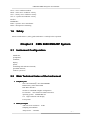
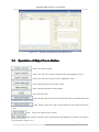
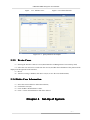
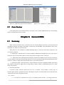
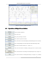
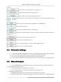
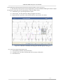
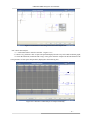
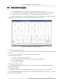
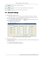
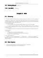
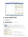
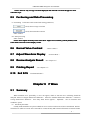
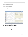
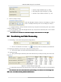
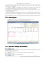
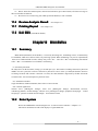
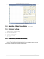
Qinhuangdao Contec Medical Systems Co., Ltd
Feb. 2008
CMS6600 EMG/EP System User Manual
Chapter 1
Summarization
EMG/EP system is based on electrophysiological detection principle. It is valuable on diagnosing
neurogenic diseases and myogenic pathological changes, orientating neurogenic pathological changes, degree
of damage and Prognosis.
The application value of electrophysiological detection technology is increasing, which is mainly
because that whether potential exercises or potential feeling can be analyzed using quantitative analisis along
with the improving of record establishment and standardization of methodology. The value of quantitative
analysis is as follow:
1. Can expatiate on the severity of the disease exactly .
2. Can compare the patient’s along with the changes of time when the disease is progressing .
3. Can compare the results of patients tested by different people .
4. The change displayed through fix quantify can not be recognized by subjective analysis .
From here we can see, it not only evaluates the pathological changes objectively, orientates the
neurogenic pathological changes correctly, but also evaluates the around nerval function characters correctly.
EMG/EP system is with a view to the above points. With the advantages of easy operation, clear test,
exact record and beautiful interface, it helps a lot when the doctors of neural surgery, internal medicine,
rehabilitation , Ophthalmology, pediatrics etc. diagnoses.
1.1
Functions of the Instrument
EMG test;
SCS test;MCS test;F Wave test;H Reflex test;Blink Reflex test;RNS test;
BAEP test;VEP test;SEP test;
1.2 Applied Scope of the Instrument
EMG is widely used in distinguishing whether the muscle weakness and amyotrophia are caused by
disease or deliration or other reasons,whether the disease is chronic or active,whether the muscle still be
renewable etc.
Neural conduction can be used in diagnosing the diffuse and multiplex deliration, confirming a certain
focal lesions, judging neural damage etc.
The clinic evoked potential can assist in identifying suspicious lesions in the central nervous system,
testing clinic lesions, helping the disease location, monitoring the function state of feeling system etc.
By using the machine, doctors can judge the details of the disease through the measurement of MCS,
SCS, FWave, HReflex, EMG, BlinkReflex, RNS, SEP etc., and make a specified treatment programmes,
estimate the medical costs etc.
- 1 -
CMS6600 EMG/EP System User Manual
1.3
1.3.1
Involved Contents of the Instrument
Electrode
(I) Categories of the electrodes
Surface electrodes: lightly friction at the site of the skin, and erase the lipin, feculence and skin flakes,
then wipe gel on the surface to fix it on the skin.
Monopole pin electrode: before use, the pinhead should be disinfected strictly, the skin should be
disinfected by alcohol etc. When using, it should be inserted under the skin at a tangent angle. When the
electrodes is inserted, it should be fixed on the clothes or skin by clips or other things to avoid fault trace
caused by dragging leads or leads swinging.
(II) Antisepsis of the electrode
The reusable pin electrode should be disinfected by high temperature and pressure. Aside, if some pin
electrode with leads or canal can not stand high temperature or high pressure, it can also be disinfected by
Ethylene oxide steam.
(III) Placement of the elecstrode
See each test item summarization for detail operations
1.3.2 Test Part
(I) General EMG
(II) Nerve conducting test
1 Median nerve
Median nerve is the surface nerve. Its nerve stem can be stimulated at Erb, oxter, elbow, wrist.
Check the stimulating
and recording point of
the conducting speed of
Median nerve
(A) exercise conducting
speed
(B) orthodromic sense
conducting speed
2 Ulnar nerve
- 2 -
CMS6600 EMG/EP System User Manual
Check the stimulating
and recording point of
the conducting speed of
Ulnar nerve
(A) exercise conducting
speed
(B) orthodromic sense
conducting speed
3 Oar nerve
Check the stimulating and
recording point of the
conducting speed of oar
nerve
(A) exercise conducting
speed
(B) orthodromic sense
conducting speed
4 Shank nerve
Check the stimulating
and recording point of
the conducting speed of
Posterior shank nerve
(A) exercise conducting
speed
(B) orthodromic sense
conducting speed
- 3 -
CMS6600 EMG/EP System User Manual
5 Calf nerve
Check the stimulating
and recording point of
the conducting speed of
calf nerve
(A) exercise conducting
speed
(B) orthodromic sense
conducting speed
1.4
Features of the Instrument
(1)The software is the most popular international window system “Windows”, which has a friendly interface
and easy operation;
(2)The software uses modularization design, which is easy to extend the function and update the version;
(3)Self-contained patients archives management system, patients’ data storage and fast read;
(4)high speed and big capability HD, which can store a lot of information;
( 5 ) The whole hardware system uses integrated design, which is easy for compact configuration and
convenient move.
(6)The system equipping—medical special isolated power to make sure of tested people’s safety.
(7)The system has high anti-jamming ability, and requests less for the lab.
1.5
Common Terms used in EMG/EP
EEG -- electroencephalogram
EP -- evoked potential
SEP -- somatosensory evoked potential
SLSEP -- short-latency somatosensory evoked potential
SCEP -- spinal cord evoked potenntials
AEP -- auditory evoked potential
BAEP -- brainstem auditory evoked potential
ABER、ABR -- audio brainstem evoked response
MLEP -- middle latency response or middle latency evoked potential
VEP -- visual evoked potential
PRVEP -- pattern reversal visual evoked potential
ERP -- event related potentials
ERG -- electroretinogram
EMG - -electromygram
- 4 -
CMS6600 EMG/EP System User Manual
NCS -- nerve conductor studied
MCS -- motor nerve conductor velocity
SCS -- sensory nerve conductor velocity
SCCV -- spinal cord conductor velocity
Hreflex
BlinkReflex
RNS -- repetitive nerve stimulation :
IOM -- intraoperative montoring
1.6
Safety
Please read the annex 1 (safety guide) and annex 2 carefully before operation.
Chapter 2 CMS 6600 EMG/EP System
2.1
Instrument Configuration
Mainframe,
preamplifier,
stimulator,
display,
printer,
stimulating and collection electrode,
grounded electrode,
software system etc.
2.2
Main Technical Index of the Instrument
1 Computer part
CPU: Intel PentiumⅢ more than 800MHz
EMS memory: More than 256M
HD: More than 40G
CD driver: CD-ROM or higher configuration
I/O interface: more than four USB2.0 interfaces
operating system: WINDOWS XP
17# high resolution color display
Laser printer
2 Main system part
A/D conversion resolution 16 Bit
Sampling ratio 200kHz
Analysis time 5-5000ms
- 5 -
CMS6600 EMG/EP System User Manual
Stimulating frequency 0.1-50Hz
3 Amplifier part
four leads
sensitivity 0.05μV-20mV/Grid
earth noise EMG <= 4μV(Vpp)
EP <=0.1μV(Vpp)(1000 times in average)
Common-mode rejection ratio >= 100dB
50Hz Ban wave setting
upper limit Filter-frequency 20kHz
lower limit Filter-frequency 0.01Hz
plus amplifies 25 times-400000 times
4 Stimulator part
Current stimulator: constant current 0.2-100mA
loading protection
Chapter 3
3.1
pulse width 50-1000μ S
short circuit and over
Management of Case History Pool
Enter System
After the assembling of instrument is finished, turn on the main power, and then the software and
hardware of the system will be automatically checked. (Figure 3-1-1)
Figure 3-1-1 Interface of system self test
When the check passed, it will enter an interface indicating Management of Case History Pool(Figure 31-2).
- 6 -
CMS6600 EMG/EP System User Manual
Figure 3-1-2
3.2
Interface of management of case history pool
Operation of Major Press-Button
Click, Cases will be deleted;
Click, Cases will be put into the system(Saved in the upgrading version);
Click, Cases will come out (Saved in the upgrading version);
Click, entering an interface set by the system;
Click, entering an interface of Item Option;
Click, quit the system;
Click, then the right side of the current interface will be turned into Advanced
Search of Cases(Figure 3-3-2);
Click, then the right side of the current interface will be turned into Revise
Cases;
Click, then Cases will be saved in system;
Click, then the right side of the current interface will indicate you to fill in a case history
of a new patient(Figure 3-3-1);
- 7 -
CMS6600 EMG/EP System User Manual
Click, then the query you have put in will be cleared;
Click, then you can search the case according to your query;
3.3
Specific Operation
3.3.1 Add Information of New Patients
(1)Entering the interface of New Patient (Chart 3-3-1) (Figure 3-3-1)and then fill in the information of the
patient;
(2)Click OK and entering the interface of Item Option, then the relevant items will be checked;
(3)Click Cancel, then the information of new patients will be canceled.
3.3.2 Query of Cases
(I)Quick Query
(1)On the top of the interface, Click any option at Quik Search such as Time(T), Name(N) or Order(O);
(2)Fill in relevant query at Quik Search and then the cases list will be displayed;
(II)Advanced Query
(1)Enter the interface of Advanced Search(Figure 3-3-2)
(2)Choose query condition at Search Condition (AND:All Match;OR:Match is Ok;Faintness
Search::For instance, put into the name of Zhang Xiao, then Zhang Xiaoling can be found in this query);
(3)Choose query condition to fill in under Search Condition;
(4)Click Execute(E), then Click “ SURE”, and then relevant records accord with conditions will be
displayed in the case list;
(5)Click Clear(C), and then the operation will be cleared.
(6)Example: You want to query the case with No. 1, name Robert, you can Click
after Search
Condition and tick
, set
after Case, put 1 into the edit bar and then execute the
fourth step, and then results come out. (Figure 3-3-3)
- 8 -
CMS6600 EMG/EP System User Manual
Figure 3-3-1 Add New Case
Figure 3-3-3
3.3.3
Figure 3-3-2 Advanced Search
Query Result as an example
Revise Cases
(1)Entering the interface of Revise Cases( Initial Interface of Management of Case History Pool)
(2)Select the case need to be revised from the case list, and then the information of the patient will be
displayed at the right side of the interface;
(3)Revise
(4)After the revising is finished, click Save Case(V) to save the revised information;
3.3.4 Delete Case Information
(1)Select the case needed to be deleted from the list;
(2)Click Delete Case(D)
(3)Click “SURE” and then delete is done;
(4)Click “ Cancel” and information will not be deleted.
Chapter 4 Set-Up of System
- 9 -
CMS6600 EMG/EP System User Manual
4.1
Enter System
Entering the interface of the Set-up of System from the interface of Management of Case History Pool, see
Figure 4-1-1
Figure 4-1-1 Interface of Set-Up of System
4.2
Operation of Major Press-Button
Click, and then entering the set-up of system for check up of general EMG
(electromygram) (Figure 4-4-1);
Click, and then entering the the set-up of system for MCS ( motor nerve conductor
velocity);
Click, and then entering the set-up of system for SCS ( sensory nerve conductor
velocity);
Click, and then entering the set-up of system for F wave inspection and measurement;
Click, and then entering the set-up of system for Hreflex;
Click, and then entering the set-up of system for repetitive electricity stimulation;
Click, and then entering the set-up of system for BR (blink reflex ) ;
- 10 -
CMS6600 EMG/EP System User Manual
Click, and then entering the set-up system for VEP (visual evoked potential)
Click, and then entering the set-up system for BAEP ( brainstem auditory evoked
potential)
Click, and then entering the system for SEP (somatosensory evoked potential);
Click, and then entering the set-up system for normal numerical value;
Click, and then it will set the color for relevant objects;
4.3
Set-Up for Information of Hospital and Doctors
(I)Hospital Information
Fill in the information at Hospital Information.
(II)Doctor Information
(1)Fill in the information at Doctor Information
(2)Click Add, and then the doctors’ information will be added (at most 10 pieces of information).
(3)Click Delete,and then the information will be deleted from the list.
(4)Select the information needed to be revised from the list, Click Modify and then done with..
4.4
Check-Up the Settings of System of Items
Take general EMG(electromygram) test as an example, tests of other items are similar to it.
(1)Enter the setting of system of general EMG test(Figure 4-4-1);
(2)At Color Settings, set the color options such as Background Color of Display Area, Gridding Color of
Display Area, Color of Wave Form, Color of Text, Color of Sign and so on.
(3)At Display Settings, select and set the speed of scan and sensitivity of wave form display. For other
items, there are display mode as well.
(4)In the Hardware Param Settings, you can set up Channel, high-pass filtering parameters, low-pass filter
parameters, and magnification settings such as Notch
(5)Click Save as Default, name it and save;
(6)Click Use style, choose the selected interface setting,(records in the list are factory setting, we suggest
you not change)
(7)Click Delete to delete the record
(8)Click APPLY to save the setting, and put the setting into practice
(9)Click Ok to apply and quit;
(10)Click Cancel to qiut whitout saving
- 11 -
CMS6600 EMG/EP System User Manual
Figure 4-4-1
Interface of QEMG Settings
Chapter 5 Project
5.1
Selection
Enter System
Select the patient from the Case Management Interface then go to the selection interface.
5.2
Operation of Major Press-Button
Click, enter into EMG detection system;
Click, choose Corresponding nerve detection system from the Pop-up menus;
Click, enter into related report print ;
Click , return to Case Management Interface ;
Select, examine the left body;
Select, examine the right body.
- 12 -
CMS6600 EMG/EP System User Manual
Click , add a muscle and nerve to Primary Part ;
Click, delete the name ;
5.3 Enter General EMG Testing System
(Figure 5-3-1)
( 1 ) Choose the muscle(e.g.brachialis) under the scroll of Primary Part, click EMG to enter into the
systems.
(2)Or select the muscle from the fingure muscle,click EMG to enter into the systems.
Figure 5-3-1 The second way to enter EMG testing system
5.4
Enter Nerve Conduction Testing System
Choose the Nerve(e.g.deep peronel ner) under the scroll of Primary Part, the following two ways to enter
Detected nerve conduction interface.
(1)Click NCS, select the test item(e.g. MCS),then enter the systems.
(2)Or select the Nerve from the fingure nerve,select the test item(e.g.MCS),then enter the systems.
- 13 -
CMS6600 EMG/EP System User Manual
Figure 5-4-1 The second way to enter MCS testing system
5.5 Add Testing Part
(I)Click the button ADD, the figure 5-5-1 will come out.
(II)Select the muscle in the left window, or choose the nerve in the right window.
(1)Click the button ADD,the button OK will come out.
(2)Click OK to add the selected items into Corresponding directory, then close the dialog box.
(3)Click Cancel to quit without any action.
5.6
Printing Report
Printing
(this operation is used after testing)
(1)Click Report to enter the report interface(Figure 5-6-1), data with the mark * can be printed.
*,If
NOTE: 3 * stands for root of the data,2 * stands for 3 * sub-item,1* stands for sub-item of the former two
choose the sub-data, its roots must be selected items.
(2)You can choose the default data, also can choose the needed date,then print it.
(3)Click OK to enter Diagnosis of EMG interface(Figure 5-6-2),then print.
(4)Click Cancel to return to the Project Selection Interface.
- 14 -
CMS6600 EMG/EP System User Manual
Figure 5-6-1 Report of project selection interface
5.7
Figure 5-6-2
Diagnosis of EMG interface
Case Review
If the patient has been examined, history will appear in the button ADD.Double-click corresponding
options, the information can be recalled.
Chapter 6 General EMG
6.1
Summary
EMG records electrical activity of muscles from the cells,and judges the muscle system function and
morphologic changes according to the changes of motor unit potential.EMG is the determination of the entire
movement as a means of system functions.
When muscle in the examination of EMG,Shrinking degrees of force,the motor units ,frequencies, the
waveform are different.
(1)Simple phase: when the muscle is int the condition of Mild normal strength,only one or a few units to
participate in sports contraction,a discrete motor unit potential will appear on the waveform.
(2)Mixed phase:Also called potential weakening of interference,Medium level of muscle contraction
force,the number of the motor unit potential will increase .Some regional potential density,individual potentials
can not be isolated , a single motor unit potential can be seen in some regions of ;
(3)Interference phase: when the muscle is int the condition of greatest strength,the number of the motor
unit potential will increase, Motor units overlap density complex, unable to differentiate between a single
motor unit potential.
(I)Electrode placement:
Concentric needle electrode inserted into the use of location, record samples of three types of
activities,Insert activities, spontaneous activity and arbitrary activities, electrodes must be moved in the muscle,
and write down records of regional activities.
(II) Notice:
(1)It is better to fix Sensitivity on 10 ms / D (scanning speed), 100 mV / D (vertical sensitivity),
- 15 -
CMS6600 EMG/EP System User Manual
because the level of sensitivity will affect the measurement .
(2) With a fixed magnification (1000) is a very important aspect, in particular the establishment of the
normal range.
( 3 ) Special attention: Two types of patients do not EMG:A:Bleeding tendencies B: Susceptible to
repeated, systemic infection;
(4)For valve diseases, after examining needle electrode, the transient bacteremia, endocarditis can lead
to these patients also best to avoid using needles to inspect;
(5)Pins and needles in the mobile location of the electrode process can lead to muscle damage, and a
local inflammatory response, may also be occasional pathological changes in the muscle. Therefore, EMG, it is
best not conducted in the same muscle biopsy site
(6)In order to avoid confusion, serum muscle enzymes in the best inspection prior to the EMG test
(7)EMG is a traumatic inspection, pins, some patients may feel particularly unwell and therefore not
acceptable to patients. At this time, EMG, you'd better consult physicians.
(III)Clinical application:
Used to detect myopathy, encephalopathy, spinal cord and nerve root lesions (such as Sishitan, respiratory
failure, etc.), multiple peripheral neuropathy, amyotrophic lateral sclerosis, such as CIP.
(IV)The analysis indicators:
Analysis of major motor unit voltage (motor unit potential, MUP), the calculation of the time-MUP,
amplitude, rise time, size, phase and turning point. Provide real-time waveform scanning system, in different
muscles on the degree of muscle strength characteristics of discharge.
6.2
Enter System
From the selection of projects interface (Chapter 5.3) entered the QEMG data sample System Interface
(Figure 6-2-1):Interface column shows the title of the test items QEMG name, location Test Part detection,
detection mode DEMO or REAL, case-related information;The status bar displays a prompt information (eg
READY) and real-time time display is left amplitude sensitivity (such as 100 mV / D), the right for the
scanning speed (such as 10 ms / D).
- 16 -
CMS6600 EMG/EP System User Manual
Fingure 6-2-1 Interface of QEMG data sample
6.3
Operation of Major Press-Button
Click, set hardware parameters
Click, print screen;
Click, pause protracting waveforms;
Click, continue to protract waveforms;
Click, switch between concentrated display and normal display for the waveforms;
Click, exchanged display between IP analysis datas and manual analysis datas;
Click, back to item choice interface, see Figure 5-3-1;
Click, enter the interface of manually selecting sport unit, or process IP data
analysis;
Click, enter the interface of checking revised and picked sport unit, see Figure 6-52 ( manually analyze);
Click, enter the interface of checking data analysis, see Figure 6-5-3 ( manually
- 17 -
CMS6600 EMG/EP System User Manual
analyze);
Click, back to the collect interface, see Figure 6-2-1;
Click, enter the normal value data interface;
Click, choose if processing checking again or not ;
——
Click, the number of the waveform in the display area is same with the number on the
button;
Click, give up the examine analysis of MultiMUP、ManMUPor IP;
Click, process IP analysis;
Click, process automatic analysis, see Figure 6-6-1;
Click, process manual analysis, or enter the interface of manually selecting sport unit, see
Figure 6-5-1;
Click, save the waveform datas on the screen;
Click, if choose high filtering or not;
Click, store dribs and drabs ( can store 4 dribs and drabs at most);
Click, replay relevant dribs and drabs;
6.4
Parameter Settings
(1)Click Settings button to set hardware parameters ( standard EMG adopts single-channel gathering);
(2)Choose to set the scanning speed at the Sweep position ( horizontal sensitivity);
(3)Choose to set the amplitude at the Senstivity position ( vertical sensitivity);
(4)It can also carry through the system settings according to 4.4 section, but we do not suggest this way.
6.5
Manual Analysis
(1)Click ManMUP button on the gethering interface, it will appear Analyse button on the left below
angle of the interface after 5 seconds;
(2)Click Spont button, give up analysis of present time;
(3)Click Analyse button to enter interface of manually selecting sport unit.
(I)Manually selecting sport unit
(1)When the mouse glides on the waveform, the red pane glides with it together;
(2)Click the left button once, it will pop-up a dialog box ( as shown in Figure 6-5-1),and will display the
- 18 -
CMS6600 EMG/EP System User Manual
basic information of the potential of the chosen sport unit: Phases, Turns, [uV], [ms];
(3)Put the mouse at the position of left or right nonius, press the left button and drag the nonius to adjust
the position of sport unit, the relevant parameters will also change with it;
(4)Click Delete, give up selecting and select again;
(5)Click Accept , save the chosen one and go along the next select;
(6)Repeat the above operation, select random numbers of sport unit ( 30 at most).
Figure 6-5-1 Interface of manually selecting sport unit when pop-up a dialog box
(II)Check revised and selected sport unit:
(1)Click Summary button to enter the interface;
(2)Using the same way when selecting sport unit to pop-up a dialog box;
(3)Check and revise
- 19 -
CMS6600 EMG/EP System User Manual
Figure 6-5-2 Interface of checking revised and selected sport unit
(III)Check data analysis:
(1)Click Data button to enter the interface(Figure 6-5-3);
(2)Check every parameter value of sport unit potential displayed in the ways of list and coordinate graph;
(3)Check the maximum, minimum and average value gotten from the comparison and calculation for the
same parameter of each sport unit potential ( displayed in the following list) .
Figure 6-5-3 Interface of data analysis of analyzed manually
- 20 -
CMS6600 EMG/EP System User Manual
6.6 Automatic Analysis
(1)Click MultiMUP button, it will pop-up a schedule dialog box after 5 seconds;
(2)Click Spont button before the apperance of this dialog box to give up the analysis of present time;
(3)Enter the interface of sorted situation for sample waveform automatically (Figure 6-6-1);
(4)Observe sample waveform situation and asjust sample sortation manually ( Above is the container
which displays 12 sample waveforms, it can display 12 sample waveforms at most).
Figure 6-6-1 Interface of automatic analysis
(I)Sortation of sample waveforms:
(1)If you think two kinds of sample waveforms belong to one kind, put the mouse on one of the sample
waveform;
(2)Press the left button of the mouse and drag it to the other sample;
(II)Delete sample waveform:
(1)Place the mouse on the sample container;
(2)Click the right button once, it will pop-up "make sure delete this sample ?";
(3)Click "Confirm" to delete;
(4)Click "Cancel" , not delete.
(III)Display sample waveform:
Click left button twice on the sample container, the continual waveform area will display the best and
complete sample waveform.
(IV)Change the nonius:
Adjust the two foul lines on the continual waveform area to change the nonius of relevant sample.
(V)Click ManMUP button to enter the interface of selecting sport unit manually(Figure 6-5-1), operation
next is same with manual analysis.
- 21 -
CMS6600 EMG/EP System User Manual
6.7
IP Analysis
(1)Click IP button;
(2)Click Analyse button, collect 400ss' datas to analyze. Analyze once per click.
(3)Observe the analized result in IP data display area (Figure 6-7-1) .
Figure 6-7-1 IP data display area
6.8
Review Analysis Result
(I)Does not exit QEMGchecking review:
(1)Back to gethering beginning interface;
(2)It appears relevant buttons on the interface, click to review every information.
(II)Exit QEMGchecking review:
(1)Back to item choice interface, the system saves the patients' information to document with the
extention name .rep automatically;
(2)Enter the gathering interface as 5.7 section;
(3)Click relevant buttons to review information;
(4)Click RunAgain, choose to click " Confirm" to check again.
6.9
Printing Report
See 5.6 section.
6.10
Exit General EMG System
Click Menu button on the gathering interface ;
- 22 -
CMS6600 EMG/EP System User Manual
Chapter 7 MCS
7.1
Summary
(I) Electrode placement:
(1)Normally adopts stimulator with the distance 2-3 cm beween positive and cathode. Place the cathode
on the far end of the nerve to arose the nerve depolarization, and the positive on the near end to arose
overpolarization to block the spread of impulse.
(2)First stimulate with low intensity, look for the best position with cathode to arose the most obvious
muscle action potentials;
(3)Then increase the stimulating intensity until super intensity to place a premium on a biggest muscle
action potential. The amplitude of muscle action potential is big, so do not need to occur repeatedly. Once
stimulate can be recorded to waveform.
So no need to superimpose, waveform can be recorded through one stimulation.
(4)Double surface electrodes are usable to record. Active electrode on muscle belly and referenced
electrode on muscle tendon.
(II)Notice:
(1)It is better to issue similar muscle action potential to test different stimulation, or mistake may occur;
(2)Preclinical mensuration should be carried out in fixed magnification multiple; the condition for
magnification is the same with that for normal value.
(3)MCS speed is affacted by body temperature, so it should be tested in warm room between 21-25℃.
Theoretically speaking, 26 - 28℃ even 30℃is better.
(III)Clinical application:
Ambient nerve disease (e.g.demyelination )、systemic disease (e.g.Kugelberg-Welanser、WerdnigHoffmann in motor neuron disease)、pathological changes for nerve and muscle tie-in、primay muscle disease
(e.g. Seasonal anaesthetization、tonic muscular weakness).
(IV)Systemic analyse index:
(1)Latency: time from artefact to induced potential jumping-off;
(2)MCVcaculation:
MCV(m/s) = D(mm) / (Latency (p)- Latency(d))(ms)
D: two stimulation points cathode-cathode distance;
Latency (p): latency for nearer stimulation;
Latency (d): latency for farer stimulation
7.2
Enter System
Enter MCS interface from item select (Chapter 5.4)(Figure 7-2-1):
Contents of title bar and status bar are the same with general electromyogram test.
- 23 -
CMS6600 EMG/EP System User Manual
Figure 7-2-1 Interface of MCS
7.3
Operation of Major Press-Button
Click to test right body test (asynchronous with Left button);
Click to test left body test (asynchronous with Right button);
Click to enter sensory nerve conductivity test;
Click to enter F wave test;
Click to enter H reflection test;
Click to dtart body surface test;
Click to print screen;
Click to enter normal data interface;
Click to check contrast with normal data (graphics);
Click to erase appointed waveform;
Click to check contrast with normal data (data);
- 24 -
CMS6600 EMG/EP System User Manual
Click to set hardware parameter;
Click to exit from test system and back to item selection interface;
Click to back to waveform selection interface.
7.4
Parameter Settings
I. Amplifier (hardware) parameter settings:
(1)Modify system setting: refer to 4.4 Warning: please don't change system parameter optionally.
(2)Click Settings button(or the button corresponding to the Settings button's position in instrument
panel) and set in the dialogue box appeared as follows:(Figure 7-4-1):
A. Pitch on unlimbered collection channel(e.g.
), make high-pass filtering, low pass
filtering, magnification times and trap settings.;
B. Click OK, to confirm the settings
C. Click Cancel to cancel.
Figure 7-4-1 Dialogue box for amplifier parameter settings
II.
Body surface impedance check:
(1)Click Imp Test button(or the one corresponding to this button's position in instrument panel), Figure
7-4-2 dialogue box appears:
(2)Click It’s OK to show eligible for further test;
(3)Click Quit to show unqualified to give up this test;
- 25 -
CMS6600 EMG/EP System User Manual
Figure 7-4-2
III.
Dialogue box for body surface impedance
Input stimulation toponymy:
(1)Find
line;
( 2 ) Click sheet which needs to be inputted the information into with left key of the
mouse(e.g.
) to make the sheet under input condition;
(3)Input name and system will autosave.
IV.
Conductive distance input:
Find
line; the means is ditto.
V.
Sensitivity display settings
Changing condition for sensitivity is on top of collection display: upright sensitivity (e.g. 5mV/D) and
level sensitivity (e.g. 10ms/D).
(1)Upright sensitivity: Click up and down direction key in keyboard or instrument panel. Up to minish
sensitivity and down to increase.
(2)Level sensitivity: Click left and right direction key in keyboard or instrument panel. Left to minish
sensitivity and right to increase.
VI.
Stimulation parameter settings:
(1)Stimulate electric current intensity: Press left key of the
mouse and grag scroll bar under Intensity. Intensity will be
stimulated to minish to the left and increase to the right. Or it
could be adjusted through the arris adjustment in instrument
panel;
(2)Stimulation frequence: Click list under Rate and choose
relevant frequency value, or adjust through rise and descend
buttons labeled "frequency" in instrument panel;
(3)Stimulation pulse width: Click list under Duration and
- 26 -
CMS6600 EMG/EP System User Manual
choose relevant frequency value, or adjust through rise and descend buttons labeled "pulse width" in
instrument panel
VII.
Input information settings:
(1)Recording Site: Display record part, e.g. Soleus.
(2)Temperature: Input environment temperature, e.g. 25℃. (the
input number shoule be between 0 to 100, or dialogue box for
reference will appear. Click ok to input again)
7.5
Fuctioning and Data Processing
(I)Fuctioning(It can collect after parameter settings finish.)
Click, stimulator carries through single stimulation;
Click, stimulator carries through continuous stimulation;
Click, stimulator stops stimulation;
Click, it carries through the first test and the data will show in case history review. If waveform is
not clear, please adjust sensitivity;
Click, it carries through the 2nd test and the data will show in case history review. If waveform is
not clear, please adjust sensitivity;
Appear after Run 1 and Run 2 carry out at the same time. Click, test data for twice will show at the
same time, which is convenient to contrast;
Erase waveform:
(1)Choose appointed waveform (e.g.
);
(2)Click Erace Trace button to erase selected waveform;
(3)If cannot see clearly, select "Normal" from "Wave Display Mode" and erase after it shows normally.
Note:: Waveform display adjustment can be referred to 5.3.7
Note
(II) Data processing:
(1)System will mark and process data after collect data. The result displays in List 1 and 2.
List 1
- 27 -
CMS6600 EMG/EP System User Manual
List 2
(2)Adjust mark position manually: Put mouse on discretional mark in collection dection and drag the
mark by pressing left or right key, the related data will change; Press right key of the mouse and drag the first
yellow mark, then the 2nd mark will adjust position automatically.
Note:: Cross mark is used to sign wave crest and trough. Upright mark is used to sign
Note
interphase.
7.6
Normal value Contrast
(1)Enter interface for normal value contrast;
(2)Check normal value;
7.7 Adjust waveform Display
I. Whole adjustment:
Choose "Normal", waveform displays normally (dispersedly);
Choose
"Congregate",
waveform
displayscentralizedly
(progressively).
II.
Partial adjustment:
(1)Press
or
, choose related waveform needs to adjust (e.g.
), press left or right key of the
mouse in collection section and drag selected waveform to pointed position.
(2)Click
or
again after adjustment and then can adjust mark operation manually. (
be used only when click R1&R2; it is used to grag red waveform for reference)
7.8
Review Analysis Result
Refer to 5.7;
- 28 -
will
CMS6600 EMG/EP System User Manual
7.9
7.10
Printing Report
Exit MCS
(refer to 5.6)
(Click Menu)
Chapter 8 SCS
8.1
Summary
In order to record SCS, usually it needs to stimulate peripheral nerve in finger or toe, collect straightly in
proximal end; or stimulate nerve cord and collect from finger or toe conversely. Usually the pain can be
reduced with surface electrodes and reliable potential can be acquired by using average technology. But pin
electrode is needed to collect for some severe cases.
(I)Electrode placement:
(1)Put the cathode on nerve, and anode should be along this nerve but away from cathode.
(2)Generally speaking, stimulation mark is samll when grounding electrode; it canbe put anywhere
convenient when the mark doesn't effect waveform so much; when the effect is obvious, put the electrode
everywhere to check;
(3)Put active electrode on nerve, while put refrenced electrode which has some distance with the nerve
which may effect it.
(II) Notice:
(1)Better not use too powerful stimulation intensity;
(2)Keep skin between stimulation electrode and record electrode dry;
(3)Nessary to use average technology;
(III) Clinical application:
Ambient nerve disease (e.g.demyelination ) 、 systemic disease ( e.g.SCD 、 B12 avitaminosis )、
pathological changes for nerve and muscle tie-in、primay muscle disease(e.g. Seasonal anaesthetization、tonic
muscular weakness).
8.2
Enter System
Enter SCS interface (Figure 8-2-1) from Item selection interface (Chapter 5.4):
The content about title and status is the same with EMG test.
- 29 -
CMS6600 EMG/EP System User Manual
Figure 8-2-1 Interface of SCS
8.3
Operation of Major Press-Button
Click, enter SCS
Others are same as MCS.
8.4
I.
Parameter Settings
(Others are same as MCS.)
Sensitivity display settings:
Click during collecting data. Adjust sensitivity of waveform according to (1) and (2)
Click and adjust average waveform according to (1) and (2).
(1)Upright sensitivity: Click up and down direction key in keyboard or instrument panel. Up to minish
sensitivity and down to increase.
(2)Level sensitivity: Click left and right direction key in keyboard or instrument panel. Left to minish
sensitivity and right to increase.
II. Input information settings:
(1)Recording Site : Input record part ;
(2)Temperature : Input environment temperature ;
- 30 -
CMS6600 EMG/EP System User Manual
Notice: There is only average waveform displayed and collected waveform disappears when
Notice:
collection stops.
8.5
Fuctioning and Data Processing
(I)Fuctioning(Collection can be started after setting parameter):
Click, show average waveform
Click, show smooth waveform.
Same as MCS
(II)Data processing
Same as MCS
Notice:: don't adjust manually when collect data. Adjust level sensitivity (usually dimish) when
Notice
some marks cannot be seen in display section
section.
8.6
Normal Value Contrast
(Same as MCS.)
8.7 Adjust Waveform Display
8.8
Review Analysis Result
8.9
Printing Report
8.10
Exit SCS
(Same as MCS.)
(See Chapter 5.7)
(See Chapter 5.6)
(Click Menu button)
Chapter 9 F Wave
9.1
Summary
When stimulate nerve powerfully, F wave can appear, which is after M wave. Following should be
analysed: F-M wave largest delitescence difference、F-M wave smallest delitescence difference、F-M wave
average delitescence difference 、 how many times Fwave appears 、 amplitude 、 rate of occurrence and
conductive speed.
(I) Electrode placement:
Usually anode should be away from cathode or nerve cord to avoid conversed nerve interdiction. Surface
electrodes are usable to record. Active electrode is on muscle belly and referenced electrode on muscle tendon
- 31 -
CMS6600 EMG/EP System User Manual
(II) Notice:
Better not use long-time stimulation when there is F wave and frequency not more than 0.5Hz to avoid
effect from former stimulation to next waveform.
(III) Clinical application:
GBS、HMSN、diabetic neuropathy、uremic neuropathy、root or peripheral neuropathy、ALS、moytubular
syndrome、syringomyelia、multiple sclerosis ;
9.2
Enter System
Enter FWave interface (Figure 9-2-1) from Item selection interface (Chapter 5.4):
The content about title and status is the same with EMG test.
Figure 9-2-1 Interface of FWave
9.3
Operation of Major Press-Button
Same as MCS.
9.4
Parameter Settings(Others are same as MCS)
I. Input information settings:
- 32 -
CMS6600 EMG/EP System User Manual
(1)Stim.ite: input stimulation part, e.g. Wrist;
(2)Recording.Site: input record part, e.g. APB;
(3)Distance: input conductive distance, e.g. 700;
II.
Sensitivity display settings:
Click "M" and adjust sensitivity of M wave according to (1) and (2)
Click "F" and adjust sensitivity of F wave according to (1) and (2)
(1)Upright sensitivity: Click up and down direction key in keyboard or instrument panel. Up to minish
sensitivity and down to increase.
(2)Level sensitivity: Click left and right direction key in keyboard or instrument panel. Left to minish
sensitivity and right to increase.
Note:: M wave is on the left of vertical line in display section and F wave on the right.
Note
9.5
Functioning and Data Processing
(I)Functioning(It can collect after parameter settings finish):
(1)Rec.No: Click button in vertical line(e.g.
), displaying number on the button, from which the
waveform begins. When the screen is full, it will protract circularly from 1
(2)Stim Count: display waveform amount and stimulation times on screen.
(II)Data processing
(1)The system will print automaticly after collect data and carry our data processing. The result is like
Figure 9-5-1
Figure 9-5-1 F-Wave data processing result
(2)Adjust mark position: Keep pressing the left key of the mouse and drag any mark in collecting display
section.
Note: Reference the color of the mark in the system settings, Cross mark is crest and trough of M
and F wave, erect mark is letency position of M and F wave .
- 33 -
CMS6600 EMG/EP System User Manual
9.6
Normal Value Contrast
( Same as MCS.)
9.7 Adjust Waveform Display
9.8
Review Analysis Result
9.9
Printing Report
9.10
Exit FWave
(See Chapter 5.7)
(See Chapter 5.6)
(Click Menu button)
Chapter 10
10.1
(Same as MCS.)
H Reflex
Summary
Mainly to detect monosynaptic reflex of spinal cord, which can stand for the excitablity of anterior horn
motoneuron.
(I)Electrode placement:
Generally, detection methods of the H-reflex is similar to rhe stimulation and recording technology for
delitescence of measured movements, stimulative anode should be placed nearby the cathode to avoding the
anode interception;
(II)Notice:
Use stimulative pulse with longer time limit, the stimulative frequency should be low (generally choose
0.2Hz or lower); when record H-reflex generally, patient's muscle should in relaxed conditions;
(III)Clinical application:
Polyneuropathy, Lumbosacral oppression lesions, Unilateral lesions, Plexopathy, Hemiplegia, UMN
Lesions, different types of myodystonia;
10.2
Enter System
Enter SCS interface (Figure 10-2-1) through item selecting interface(Section 5.4):
The title bar and status bar will show the following content as routine EMG detection.
- 34 -
CMS6600 EMG/EP System User Manual
Figure 10-2-1 Interface of HReflex
10.3
Operation of Major Press-Button
Others same as MCS.
10.4
s
Parameter Setting
Settings
10.5
Fuctioning and Data Processing
(Same as MCS.)
(I)Functioning ( parameter setting finished, can be selected):
Same as F wave.
(II) Data processing
(1) Data-selection is finished, the system will mark automaticlly, the data processing finish. The result
will shown in List Three.
- 35 -
CMS6600 EMG/EP System User Manual
List 3
(2) Adjust the mark position: Press the left button of mouse, drag any mark in the selection area.
Note: Reference the color of the mark in the system settings, Cross mark is crest and trough of M
and H wave, erect mark is letency position of M and H wave .
(3)
10.6
shows the Max. Value of
Normal Value Contrast
(Same as MCS.)
form Display
10.7 Adjust Wave
aveform
10.8
is Result
Review Analys
nalysis
10.9
ing Report
Printing
Print
10.10
Exit HReflex
in List Three.
(Same as MCS.)
(See Chapter 5.7.)
(See Chapter 5.6.)
(Click Menu button.)
Chapter 11 RNS
y
11.1 Summar
Summary
(I)Electrode placement:
Place the active electrodes on the ultimate location of muscle, and the reference electrodes should be
placed on tendon. Choose series of active electrodes with same time-limit and shape in clinical use, to compare
their transformation.
(II) Notice:
(1) counterfeit difference : There comes factitious counterfeit difference due to the electrodes
departuring nerves casued by muscle contraction when in electric stimulation, the amplitude will show
- 36 -
CMS6600 EMG/EP System User Manual
paroxysmal increase and decrease. To avoid this situation, fistly, fasten testee's body, secondly measure
repeatly to have exact judgement.
(2) Effect by temperature and medicine: Wild temperature will aggravate MG symptom, the
electrophysiological abnormalities will be more obviously; it is better to have short-term withdraw.
(3) Detection type: Low-frequency RNS (most patient could bear), high-frequency RNS, the type is
depends on the specific circumstances.
(III)Clinical applicatio:
Repetitive nerve stimulation technology(RNS) is mainly used in researching MG (Myasthenia Gravis),
also in detecting myasthenia syndrome, botulinum toxin poisoning, antibiotics poisoning, low serum calcium,
high serum magnesium, venom etc. neuromuscular obstruction, myopathy and muscle excitability disease and
so on.
11.2 Enter System
Enter RNS interface (Figure 11-2-1) through item choosing interface (Sec. 5.4):
Content in Title cbar and status bar is same with regular EMG detection.
Figure 11-2-1 Interface of RNS
11.3 Operation of Major Press-Button
Press down, the waveform in show area will display in certain distance; eject, the
waveform will display in centralization;
Click, erase all relative data with selected waveform data case;
Click, prepare sample data;
- 37 -
CMS6600 EMG/EP System User Manual
Others are same as MCS.
11.4 Parameter Settings
I. Amplifier(hardware)parameter settings:
II. Body surface impedence check:
III. Stimulation parameter settings:
Same as MCS.
IV. Input information settings
(1)Stim Site: Input stimulative part;
(2)Recording.Site:Input recoding part;
(3)Stim Time: Input stimulative time;
(4)Temperature: Input arroundings temperature;
11.5
Functioning and Data
Processing
(I)Functioning ( Start select after finish parameter setting):
Click mouse left button to select any statistical recording pane, the rim becomes red, set the relative
message in Input Information, and set the relative hardware value in Device Settings, Click Prapare button to
prepare sample data,Click Series button to sample data。
(II)Data processing
(1) The system starts mark automaticlly after finish data selection, the data-processing complete. The
result shows in List 4.
List 4
(2) Manual adjudgment of mark position: Press the mouse left button, drag any mark in selection
display area. Any stimulation waveform has its relative mark. NOTE: Ohters are same with MCS.
(III)View the message and relative operation
Statistical pane records the start time of stimulation, stimulation frequency, and the stimulation
time (some spots in the following staff guage indicate the stimulation time), statistical area could store ten
different recording message at most.
(1) View: Select the statistical pane, click mouse left buttion, relative waveform display area and dataprocessing list show the detail recording message.
- 38 -
CMS6600 EMG/EP System User Manual
(2) Delete: Select the statistical pane, click mouse left buttion, press Erase button, all relative message to
this record will be all deleted.
(3) Re-select: If re-record in any pane which operation finished, re-run it as blank.
is Result
11.6 Review Analys
nalysis
ing Report
11.7 Print
Printing
(See Chapter 5.7)
(See Chapter 5.6)
11.8 Exit RNS ( Click Menu button)
Chapter12
12.1
BlinkReflex
Summary
Blink Reflex(Orbicularis Oculi Reflex), is caused by knocking face, stimulating cornea, or human body
be stimulated, which arose defense reflex, for protecting eyeball. When stimulating every nervus supraorbitalis,
there are two different kind of reflex, namely early reflex(R1)、 late reflex(R2)on stimulating side and late
reflex(R2')on contralateral. Test method is as following:
(I)Electrode palcement.
the subjects lies on the bed relax, closing eyes or half open eyes. The Surface recording electrode be placed on
middle of lower eyelid, the reference electrode be placed on Corner of the eye flank (the distance between
recording electrode and reference electrode is 2.0cm), the skin should be degreased by alcohol. Electrode
resistance<kΩ,the terrestrial poles be placed on wrist.
(II)Stimulation method
single stimulation, double stimulation, direct reflex of nervi facialis.
(III)Clinical application
afferent nerve pathological changes; brain axis pathological changes disseminated sclerosis,
wallenbergsyndrome, Pontine damage, efferent nerve pathological changes peripheral facioplegia 、 central
facioplegia、pontine cerebellar lesions triangle、facial muscle lesions;
12.2
Enter System
Please enter BlinkReflex interface(Figure12-2-1) from item select interface(Chapter 5.4).
The title bar and status bar with same display as regular EMG test.
- 39 -
CMS6600 EMG/EP System User Manual
Figure 12-2-1 Interface of BlinkReflex
12.3
Operation of Major Press-Button
12.4
Parameter settings
(Same as MCS.)
I. Amplifier(hardware)parameter settings:
II. Body surface impedence check:
III. Stimulation parameter settings:
IV. Input information settings:
Same as MCS.
12.5
Functioning and Data Processing
(I)Functioning(After set parameter , please start collect data.)
Figue12-5-1 shows set for collection channel and relative plus set. Click "Reset" button to reset it, the
selected channels information display on the left side of Reset button.
- 40 -
CMS6600 EMG/EP System User Manual
Figure 12-5-1 relevant channel setting
Others are same as MCS.
(II)Data processing:
Adjust mark position by manual: pressing left key of mouse, then move the mouse to selected point in the
collection display area, the date in List 5.
List 5
The upper part of collection display area is waveform of right side, the lower part is waveform of left side,
if the stimulate part is on right side, there are two marks on waveform of right side, one is for R1 delitescence,
the other is for R2 delitescence, the left side is R2 delitescence; if the stimulate part is on left side, it will be
contrary.
(III)View the data and relevant operation:
(1)
--
Symbolize channel1-10 in display area(right side);
--
symbolize left
side;
(2)
:Delete the selected waveform(in the
-->
figure it means erase Waveform 5);
12.6
Normal Value Contrast
(Same as MCS)
12.7
Review Analysis Result
(See Chapter 5.7)
12.8
Printing Report
12.9
Exit BlinkReflex
(See Chapter 5.6)
(Click "Menu")
- 41 -
CMS6600 EMG/EP System User Manual
Appendix 1 : Safety Guidance
Summary
This device is in accordance with IEC 60601-1. Belong to Type I device, it can work continuously. As a
normal device(please keep it from splashed by water), this device can not be used in a place of flammable
anaesthetic. This device should be maintained by authorized professional technical engineer. If user modify
and maintain the device without CONTEC's authorized engineer, Contec Medical Systems, Co., Ltd will not be
responsible for the security, reliability and performance. User must change parts of device with same spare
part. Please read following attentions before using this device, for avoiding possible danger.
)Request for environment
(1)
1.The laboratory should be far away from crownd and vehicle , electronic device, high frequency
electronic radiant point, for example: radiological department, department of physiotherapy, etc. For avoiding
sound, electronic interference from outside.
2. The laboratory should be silence, if necessary, please use sound insulator.
3. There should be well illumination in laboratory, which can be adjusted. During recording SEP and AEP,
the light should be pale, for patient relax, when recording VEP, it should be in dark environment.
4. The laboratory should be with well ventilation and proper temperature, which for avoid patient nervous,
sweaty or tremble. And keep the air be dry.
5. Electromagnetic interference: please make sure this device be installed and used in a environment
without strong electromagnetic interference.
(2)General request
1. This device should be installed by qualified engineer.
2. This device should be operated by professional doctor, who have been trained. The device should be
stored by special person.
3. This device should be used in the environment temperature between 10~40℃.
4. Please check the device, power cable, and make sure there is not damage in the device, which may
affect patient's security and device performance.
5. The accessory equipment, which connected with device by analog interface or digital interface, should
be in accordance with IEC standard. (for example: data processing device standard IEC950M Medical
instruments IEC standard 60601-1).all configuration should be in accordance with IEC60601-1-1. So when
engineer connect the device with signal input or output device, it should be in accordance with IEC60601-11(valid version). If you have any question, please contact us or your local distributor.
6. Grounding cable--proper grounding cable make sure the device work normally and user's security. It
needs special grounding cable, which is copper bar with diameter: 1.0--1.5cm, or a copperplate with acreage of
40cm*40cm, thickness from 2-4mm. The grounding cable should be buried in ground 1.0-1.5m. There are
charcoal and salt around the grounding cable, for reduce resistance of ground, and keep the grounding cable
contact the earth properly. The other side of grounding cable should be jointed with a steel wire with length of
80-100cm, then connected with ground pole of the main unit. After install the grounding cable, it should be
tested with Grounding resistance measurer. And test whether the grounding cable resistance in accordance
with following specification (grounding resistance <4Ω). If exceed this value, please install and test it again.
)Installation request
(3)
1. Please pay attention to power cable, and make sure nothing be hanged on the power cable, and avoid
- 42 -
CMS6600 EMG/EP System User Manual
people step on the power cable.
2. The grounding cable should working well, the grounding resistance should be less than 4 Ω, please
don't take the caliduct or water pipe as grounding cable, which may cause measure error.
3. There is vents on the rear side of the device, which is designed for ventilation, and make sure the device
work properly, keep the device working with proper temperature. All the vents holes should not be jammed or
covered. The device should be far away from heat source, which can damage this device.
4. Electric shock danger: for protect patient and doctor, the device should be used with grounding cable,
the power supply socket should be protected, the tri-lead cable can not be connected with twin wire socket.
)Attention for operation
(4)
1. This device is precise medical electronic device, which needs stable power supply. If the voltage
fluctuate great, please choose other stable power supply.
2. Without expert's permission, please don't stimulate the patient, who have embedded electronic
appliance(for example: heart pacemaker), with electrical current.
3. Please don't make any thing fall into or jam the vent hole of device, don't splash any liquid onto the
device, because it may cause short circuit when the liquid flow into the device.
4. Please don't use this device in moist environment.
5. Please use different leads properly according to the manual.
6. If you use this device in winter, please warm it before using; if you use this device in summer, please
don't use it for too long time, which may damage the device.
7. Danger of electronic shock - - Please don't open this device when operating or the power is on. Only
authorized maintenance engineer can open it..
8. Only after connect all accessories and parts properly and be checked, the device can be turn on.
9. When operating this device, please make sure it does not with condensation, When this device move to
another room, it may cause condensation. This is because different room with different temperature and the
device be exposed in moist air.
10. Only after the power cable is took off from the power supply, you can change the fuse.
11. Please don't use the stimulator when it near the shortwave or microwave therapy device in 1 meter. It
may cause unstable output and burn patient.
12. Please don't connect patient with high frequency surgical unit and EMG device, because it may burn
patient on the electrodes place or damage the stimulator or bioelectric potential amplifier.
13. When use the EMG device with other devices, please don't make electronic stimulator with voltage
higher than 400V or current higher than100 mA.
14. Operator must pay special attention when the current density >2mA r.m.s/cm2 .
15. Please don't measure the electrode resistance when the needle electrodes in patient body. For avoid
possible danger to patient.
16. For avoid possible dangers, please take off the recording electrodes and stimulate electrodes from the
device before you turn on/turn off this device.
17. During initial test, please set the stimulating current on low level, then increase the current to
expectant level slowly. This can avoid patient feel uncomfortable.
18. Please don't touch the patient and the signal input/output socket at same time.
19. If the device power off suddenly during testing, it will cause data lose.
20. If there is thunder storm or the device need be stored for a long time, please take off the power cable
from the power socket, which can avoid damage the device.
21. Please don't modify the system parameter setup. Because the default parameter set meets most use of
this device, if you do need change it, please backup the original parameter set for reference in future.
- 43 -
CMS6600 EMG/EP System User Manual
(5)Other regulation
1. The operator must read this manual and security index carefully before use this device, and operate the
device according to the manual seriously.
2. It was well considered the security request of this device on design, but operator must not neglect
observation to the patient and the status of device.
3. This device and its reusable accessories can be returned to manufacture when they are out of use span,
or disposed according to local regulation.
- 44 -
CMS6600 EMG/EP System User Manual
Appendix2 :Manual Pamphlet of Installation and Mantenance
Part 1 Standard of Main
1.Trainings shall be due before installation::
(1)Ex-installation Training;
(2)After-installation Training;
(3)Installing Training;
2.Users to be informed to plan and be prepared before installation.
3.Examing and documentation before packaging:
(1)Checking accordance of the systematic funtions(softwares), accessories, electrodes, perpherals, and
existing files to contracts of the users.
(2)Set up computer files(monther board/HD/SD/CD-ROM/printer/UPS power/monitor), retain guarantte
and other techical files for need of later repair and services.
4. Eastablsih files of product installation and acceptance:
User name,machine serial number,open case situation,grounding cable installation instruction,machine
use invironment instruction(are,around invironment,supporting facilities and preparing situation),user
operation basic situation instruction(never used before, be trainned, can operate skillfully or used
before),relative
pesonnel
record(operating
doctor,director,relative
equipment
department
pesonnel),installation instruction,acceptance situation(including user comments),installing pesonnel;
5. After-sales Service:
(1)Telephone counseling Service,operater could process the problem base on our consultation opinion.
(2)Assistant Service for Customers'equipment,operator could find out reason according to the Handbook
for Maintenace or our Telephone counseling for equipment breakdown(F&A),and take relevant measures to
solve problem quickly.;
(3) Special technical personnel will be dispatched to your place for solving problem if the above two
circumstance fails to help you.
Maintenace file about After-sales Sverive for each customer will be set up Individually, details including:
Date for Feedback,reason and breakdown part, solving measure,result.
Part 2
Preparation for Installation.
1. Request for installation location and working environment:
(1) Keep far from street or crowd, keep far from dynamoelectric equipments(such as electric
motor/elevator/transformer or building for mating electricity ).
(2) Keep far from high-rate radiation source (Radiation Dept./Treatment Dept.)
Area ≥ 12 square meters
(3) Curtain available ( Deep/shallow color for each is better)
(4) Bed/chair/doctor' operate chair/table/cabinet for file/ table for vision monitor, all is better to made of
- 45 -
CMS6600 EMG/EP System User Manual
wood..
(5)Woody floor or Seting gum on floor.
(6) An air-conditionn available,keeping the inside-temperature on 20-28 Celsius degrees, relative
humidity less than 80%.
(7) Electrical outlet or Electrical box should be matched with Air switch and Insurance device.
(8) Lighting should best be adjustable;
(9) Let the testee fell comfortable/safe/clean when conducting test;
(10) Inspection bed should be slight lower than nomal patient bed in order to let the testees get on/off
easily;
(11) If the installation location with interference source Obviously, it would be best settings (installation)
shielding room, as the case may be.
2. Installing preparation:
(1)Dedicated Ground (<= 2 ohm) (not shared with other apparatus);
(2)Prepared materials: copper board 40 * 100 (cm) (depending on thickness);
10 square foot multi-copper thread (according to the length of the scene);
Auxiliary accessories (line code, nails, and fixed copper line sets screws, Copper Rods or
galvanized steel pipe (a fixed orifice), sets of iron pipes or hoses);
Coarse salt 50 kilograms or other salt, charcoal many;
(3)Excavation Method:
Elected a nearby moist places, digging a hole with area of 1 -2 m square meters, a depth of 3
m;Embedded in the copper and around into the Copper Rods (4 1-2 meters, uniform distribution) or galvanized
steel pipe (one side sharpened, the other side bored)) and then insert into the ground floor; Use not less than 10
mm2 with the Multi-Multi-copper pipe link up with copper board (using long screws or spot welding hanged, 1
l to the ground); Layer land fill with mixed salt (preferably using industrial salt) and charcoal soil; full
irrigation; exposed place can be protected by rigid hose.
(4) Preparing Materials for inspecting room:
Small cart / disinfectant solution (including containers) / saline (including containers) / cotton bud
/ degreasing alcohol / rolls / iodine fluoride / trash / tape / wooden or plastic folder folder / link (nailed into
walls, used to or linked to stimulate electrodes) / soft foot / records T / pillow / sheets / pillow on the mat (for
inspections) check registers / inspection for single / EMG report single / single report evoked potentials.
Part 3 User Installation and Product Acceptance Work
1. Check if preparation and arrangement are ready before installing , if not, please implement as soon as
possible(prepare and work seperately are strongly recommended );
2. Open the case——》collate and clean(demolish packaging materials and discount cleaning work at the
scene)——》verify according to packing list——》Machine assembly——》Electricity testing after repeat the
test——》Collate the scene after confirming all the fuctions working nomal——finish installation。( Note:
If some problems were detected in the installation process, please sovle them as soon as possible
possible);
1. Doctors site training (Content and training requirements as the case may need);
2. patient clinical examination demostration(3-5 people);
3. User acceptance:Equipment acceptance(conducted by hospital equipment departemnt accroding to
packing list and machine working situation);Clinical acceptance(conducted by clinical departent according to
- 46 -
CMS6600 EMG/EP System User Manual
acceptance items);
4. Relations should be activley and properly handled in the process of installation and product acceptance; pay
attation to keep invironment clean and tidy;
5. The establishment of installed user files (after back to the company).
Part 4 Solution of Common Problems
[Note]
1. Safeguarding: self-maintenance (telephone answering) / user equipment by maintenance (Mail accessories
(electrode) / manufacturers Onsite maintenance;
2. Require users to keep detailed records (or description) of equipment failure phenomenon, for verifing the
reason as quick as possible, and choosing the quickest method to solve the problem.
3. Avoid disassemble and install machine blindly(User equipment department can disassemble and install
machine with the manufacture's permit);
4. If the machine is our of warranty, the manufacture will charge for material and frieght(see chapter 9);
5. If users need add inspecting items or purchase electrodes accessory, they can buy from manufactrue;
6. "Misunderstandings" and problems in the using process of the machine:
(i)Consider the machine has some problem even not familiar with the machine or not operate it correctly,
particularly under the circumstances of the habit of using machines manufactured by other companies;
(ii)Pursue more (New)inspecting items,and neglect to use each item fully,effective in clinical services,
easily end up in failure;
( iii ) Neglect the cooperation and communication between doctor and patient in the testing process(good
cooperation of patient is very important in all physical test);
(iv)normal value not be fully prepared, can not grasp essentials in clinical judgement,written reports seems be
ambiguous, which is very difficult to convince clinicians;
(v)Lack of clinical knowledge and anatomical structure relevant with the nerve and muscle system.
7. "Basic problems" appeared regulaly in the process of using of machine:
(i)Signal unable to effectively extract with high interference:
Possible reason
reason:
a . Not well grounded ( Used with other machine, connect with water pipes or heating system,grounded
connected with 220V transformers, ground cable can not meet the requirements ); patient not well
grounde ( Not marinated by salt water 、 ground cable corraded or disconnected,grounding connector poor
contact with jacks,more skin oil or too dry form large impedance);
b. strong interference source exist around the machine(Giant medical equipment X ray/CT/MR、all kinds of
medium or high frequency equipment、transformer or large electric cabinet、elevator、Radio and television
transmission tower 、 other transmission equipment,.Other possible electrical interference or medical
equipment);
c. power supply not stable(electric network interference);
- 47 -
CMS6600 EMG/EP System User Manual
d. electrodes not well sticked(or cable not well connected), Impedance too high(>5K);
e. Bad patients floating(contact with wall、metal bed or testing chair, contact with others including doctor);
Solution:
Solution
Distinguish reasons, slove seperately.。If re-wade grounding cable、Keep away from the interference source、
re-stick electrodes(check patient cable and connector)、use wooden or plastic floor in examination room 、
Avoid contact with other objects and people in testing process,shut off unrelated electrical appliances, Keep the
environment quiet and comfortable.
(ii)signal can not be superimposed or superimposed slowly,no superimpose waveform showed:
Possible reasons
reasons:
Signal saturation(Overflow),Or more with patients ground electrode stimulation of the low frequency(0.1HZ)
Solution:
Solution
Check patient ground cable, record and reference electrodes(impedance), change standby electrodes; check
stimulating frequency setup.
(iii)original signal waveform appears regular interference or some burrs, cause superimposed waveform be
deformed or eigenvalue not obvious:
Possible reason
reason:
Signal filter range seted improperly, , particularly filter frequency upper limit too high;obvious ECG
interference in acquisition electrodes ( eg.earlobe, forehead ); EMG interference caused by action of
patients(eg.frowning,swallowing,breathing etc.)
Solution:
Solution
Set correct filter frequency range; change electrodes position(shift), inform patients to be relax to reduce
action.
(iv)Doctors often complaining that"waveform can not be showed or wonderfully showed" when testing
patients:
Possible reason
reason:
If
all the parameters seted according to standard(channel, frequency range,zoom multiples,scan time
interval,display sensitivity);If electrodes are in proper position(record、reference、grounding);If stimulation
is appropriate(Stimulation anode and cathode、stimulation frequency、if Pulse width and stimulation make the
nerve enough excitement from patients、stimulation position),Many doctors in the beginner of learning could
not find the correct position of nerve or muscle or reduce stimulation for fearing or patient suffering;Patients
cooperation situation(be quiet and pay attation to stimulation source,relax, cooperation under the guidance of
doctors,correct position etc.)
Solution
Solution:
In terms of the strict inspection requirements to avoid personal granted.
(v)Doctors make inspection plan(which items to be conducted ) without considering patients' situation, can
not give a high level report after inspection:
Possible reason
reason:
Lacek of clinical experience, trainig ans confidence;
Solutioon:
Solutioon
Accumulate experience、communicate with patients,Bold but cautious;
a 70% clinical judgement, 30% inspection confirmed;
- 48 -
CMS6600 EMG/EP System User Manual
b distinguish which item should be used to inspect possible illnesses;
c Concerned about the patient's clinical performance、state of an illness、course of diseases、medical
history、family medical history、Clinicians judgement;
d Concerned about the location of focus,Affected areas,affected level,Patient prognosis;
e Common concerns (multiple, occupational), clinical manifestations and inspection characteristics;
f Bold in quantitative analysis, such as lesions, the development stage, the extent of abnormal;
[Maintenance mode classification standards]
Self-maintenance cases
cases:
(1)Treatment or all issues relating to the testing methods,include:electrodes(records,reference,grounding
electrode ) surface treatment and sticking, chioce of corrcet electrode position;stimulator set up and
use(particularly finding nerve and muscle ), patients cooperation; preparation of testing environment.These
operators must be strictly enforced as required,when there are some problems please consult manufacture or
actively solved by operators;
(2)Handling of problems related with software operation, include: basic operation process(contain all
parameters set up),testing result analysis(Including analysis of template replacement ,Choice of targets
etc.)and print.These operators must be strictly enforced as required,when there are some problems please
consult manufacture or actively solved by operators;
(3)Handling of problems related with report apply, wrtiting,registering.These operation must be in accordance
with its own hospital,And refer to other hospitals (large-renowned Hospital) standards,when there are some
problems please consult manufacture or actively solved by operators;
(4) Small Fault Handling in using equipment, including:Electrode loose 、 Fracture or other obvious
problem ( eg. Printer problem or lack or paper )。 These problems can be solved by change electordes by
operators, or contact manufacture to get suggestion or solution;
Equipment maintenance situation
situation:
1. Handling of problems related to all external power supply;
2.
Problems of cables and leads of all parts,including: power cable for main unit, special grounding
calbe,socket, monitora and monitor signal and prower cable, printer,signal and powercalbe, cable for
computer(power
cable,
tracking
ball
or
mouse,
keyboard),all
stimulatro
ourtput
cable(circut,sound,image,flash),amplifier and Program-controlled board(inside machine), machine internal
grounding cable;
3. Change fuse(standby fuse supplied by manufacture);
4. Confirm fault position accroding to all kinds of machine faults, require manufacture supply relative boards
or spare parts, and change in time to solve the problem;
5. The reconstruction of software systems (installed), and data backup and recovery processing;
So, manufacture should provide detail equipment installation mechanism(see other documents) , and
software installing instruction, and arrange primary trainning course for relative technicians.
Manufacture onsite service:
All the problems that can not be solved by operator themselves and equipment department must be serviced
and handled by technicians authorized by manufacture.
[Handling of normal problem of equipment]
- 49 -
CMS6600 EMG/EP System User Manual
1. EMG sounds accompany TV/Radio signal:
(1)Reason:not well grounded;
(2)Solution:re grounded or add one more grounding calbe connecting water pipe or other obects;
2. Impedance always greater than 10 K or harder to reduce, noise level too high:
(1)Reason:cable and electrodes not well connected;
(2)Solution:Do a good job in dealing with skin,change cable or electrodes;
3. 50HZ interference or high noise level:
(1)Reason:amplifier grounding problem;
(2)Solution:make sure amplifier well grounded;
4. Louderspeaker out of control:
(1)Reason:Computer is in a quiet state
(2)Solution:
5. Signal out of control,amplifier switch and self-test signal out of control completely:
Solution:power off the machine, unplug usb cable ,restart machine one minute later;
6. Stimulator problem:
(1)No output electric circuit: check stimulator electrodes cable;
(2)No image output:Check connecting cable and monitor power calbe;
(3)No sound output or one side has problem: check stimulator earphone;
7. Software system problem:
Part 5 Brief Introduction of the Machine
1. Main Construction
Computer systems , main unit(which includes amplifier/current/sound/image/shining stimulator), printer, all
kinds of electrodes and UPS with cables, uninterrupted power supply(option).
2. The recognization of the socket on the left side
The recognization of the channel socket
CH1-4(from down to up) means channel 1-4
+: record electrode inputting port
_: consult electrode inputting port
ISO GND: system patients’
3. Recognization of the socket in the backside
current stimulates output
- 50 -
CMS6600 EMG/EP System User Manual
audio stimulates output
video stimulates output
flash stimulates output
4. Keyboard shortcuts
function key F1-F12, stimulation adjusts knob, electric audio adjusting, pulse width adjusting,
single stimulation, serial stimulation, etc.
5. Power on and off
power on: insert the 12VDC adapter to the main unit, switch on the ship shape on-off, the indicator
light of the power supply is lightened. Confirm that the main unit is connected with the computer by USB
cable. Start the systems.
Power off: exit from the system, switch off the ship shape on-off.
Part 6 General Check-Up Parameter and Solutions
1. Standard EMG
Insert potential :
Amplifier 2KHZ-20HZ magnify 1000 times scan 100MS MUP
Analysis 50MS
Waveform shows sensitivity: 100UV/metre
Main analysis: whether the potential prolongs, features of the waveform
Record: muscle of different position(up/middle/down) and depth.
using concentric needle
Ground electrode: examine the skin and wrist (foot ankle)
spontaneous potential
Amplifier 2KHZ-500HZ magnify 5000 times scan 100MS MUP
Analysis 50MS
Waveform shows sensitivity: 50-100UV/metre
Main analysis: whether there is fibrillation potential positive phase potential myotonia potential ect.
Record: muscle of different position(up/middle/down) and depth.
using concentric needle as inserting and moving with hand
Ground electrode: examine the skin and wrist (foot ankle)
Light shrinkage:
Amplifier 2KHZ-20HZ magnify 1000 times scan 100MS MUP
Analysis 50MS
Waveform shows sensitivity: 200UV/metre
Main analysis: duration, amplitude, phasic
Record: muscle of different position(up/middle/down) and depth.
using concentric needle as inserting and moving with hand
Ground electrode: examine the skin and wrist (foot ankle)
- 51 -
CMS6600 EMG/EP System User Manual
Heavy shrinkage (most energize)
Amplifier 2KHZ-20HZ magnify 1000 times scan 600MS MUP
Analysis 50MS
Waveform shows sensitivity: 200-500UV/metre
Main analysis: features of waveform (interfere phasic/ mixed phasic/ single phasic / pathological interfere
phasic)
Record: muscle of different position(up/middle/down)
Using concentric needle
Ground electrode: examine the skin and wrist (foot ankle)
2. MCS
Amplifier 2KHZ-20HZ magnify 200 times scan 50MS
Stimulator: pulse width 200US, strength 12-16MA
Stimulating frequency 2-4 HZ
Waveform shows sensitivity: 500UV-5MV/metre
Analyzing target: delitescence, amplitude, conducting speed
upper limbs: median nerve, ruler nerve, radial nerve
lower limbs: leg nerve/calf nerve
ground electrode: between stimulation and record
3. SCS
Amplifier 1KHZ-100HZ, amplify 10,000 times, scan 20MS, superimpose 100 times.
Stimulator pulse width 200 US, strength 12-16MA
Stimulating frequency 2-4 HZ
Analyzing target: delitescence, amplitude, conducting speed
upper limbs: median nerve, ruler nerve, radial nerve
lower limbs: leg nerve/calf nerve
ground electrode: between stimulation and record
4. WAVE F
Amplifier 2KHZ-20HZ, amplify 200 times, scan 50MS.
Stimulator pulse width 200 US, strength 16-18 MA
Stimulating frequency: 0.5 HZ
Waveform shows sensitivity: wave M 500UV-2MV/METER, WAVE F 200-500UV/METER
Analyzing target: delitescence, wave F appearing frequency, wave F conducting speed
upper limbs: median nerve, ruler nerve, radial nerve
lower limbs: leg nerve/calf nerve
ground electrode: between stimulation and record
5. H reflection
Amplifier 2KHZ-20HZ, amplify 200 times, scan 50MS.
Stimulator pulse width 200 US, strength 14-16 MA
Stimulating frequency: 0.5 HZ
Waveform shows sensitivity: wave M 500UV-2MV/METER, WAVE H 200-500UV/METER
Analyzing target: delitescence, wave H appearing frequency, wave H conducting speed
lower limbs: leg nerve/calf nerve
ground electrode: between stimulation and record
6. keyboard shortcuts
please consult the user manual.
- 52 -
CMS6600 EMG/EP System User Manual
- 53 -
CMS6600 EMG/EP System User Manual
Contec Medical Systems Co., Ltd
Address
Address:TaiShan
Road 289# ·QinHuangDao Development Zone · HeBei province· China
Postalcode
ostalcode: 066004
TEL: +86-335-8508888
TEL
FAX: +86-335-8015450
FAX
Technique Support
Support: +86-335-8015427
E-mail: [email protected]
E-mail
- 54 -