1
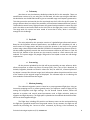
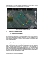
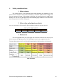
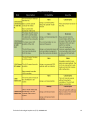
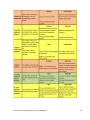
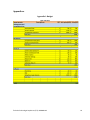
Abstract Dronolab is an expanding student club of École de Technologie Supérieure (ETS) located in downtown Montreal, Quebec. The mission of our student club is to operate fully autonomous multirotors to perform aerial surveys for various civil applications. The design and constant improvement of such a UAS involves the collaboration of several engineering fields including software, electrical and mechanical. The ingenuity, creativity and contribution of each faculty help the team achieve safe and professional flights operations For our operations, we use a DJI autopilot, the Wookong M, along with a data link on the 900 Mhz band. In order to collect and transfer data during the flight, we use a raspberry-pi based system with a pi-cam to take pictures on which we add GPS location information. The data is then sent using a high-speed 5.8 Ghz modem (Ubiquiti Bullet M5). Throughout this year, we have tested our platform for countless hours in multiple weather conditions to achieve reliable operations. École de Technologie Supérieurs (ETS)-‐ DRONOLAB 2 Table of contents 1. Description of system ............................................................................................................. 5 1. Design approach ................................................................................................................. 5 2. Mission requirements ......................................................................................................... 5 3. Design rationale .................................................................................................................. 6 4. Expected task performance ................................................................................................ 6 5. Programmatic risks and mitigation methods ...................................................................... 6 2. Description of UAS .................................................................................................................. 7 1. 3. Design description .............................................................................................................. 7 1. Aircraft ............................................................................................................................ 7 2. Autopilot ......................................................................................................................... 7 3. Ground station ................................................................................................................ 7 4. Telemetry .......................................................................... Error! Bookmark not defined. 5. Payloads .......................................................................................................................... 8 6. Processing ....................................................................................................................... 8 7. Mission planning ............................................................................................................. 8 Test and evaluation results ..................................................................................................... 9 1. Mission task performance .................................................................................................. 9 2. Payload performances ........................................................................................................ 9 3. Autopilot performances .................................................................................................... 10 4. Overall evaluation ............................................................................................................. 10 4. Safety considerations ............................................................................................................ 11 1. Safety criteria .................................................................................................................... 11 2. Safety risks and mitigation methods ................................................................................ 11 3. Risk matrix ........................................................................................................................ 11 4. Risk management ............................................................................................................. 14 5. Budget ................................................................................................................................... 14 6. Schedule ............................................................................................................................... 14 7. References ............................................................................................................................ 14 Appendices ................................................................................................................................... 14 École de Technologie Supérieurs (ETS)-‐ DRONOLAB 3 List of figures Figure 1 : 2015 UAS -‐ V8 ................................................................................................................. 7 Figure 2 : Mission planer and Ground station view ..................................................................... 9 Figure 3 : Gantt chart .................................................................................................................... 17 List of tables Table 1 : Specific flight condition .................................................................................................. 11 Table 2 : Risk matrix ...................................................................................................................... 11 Table 3 : Risk classification ............................................................................................................ 12 Table 4 : Budget ............................................................................................................................ 16 École de Technologie Supérieurs (ETS)-‐ DRONOLAB 4 1. Description of system 1. Design approach In order to build a reliable and secure UAV, we have based our latest design on the advantages our previous concepts. Last year, the main problems we had was our flight time, which was less than 10 minutes. Also, we did not have a real time image processing system. This year, our development around these two weaknesses has helped us overcome, and even exceed our goals. First, we designed our UAV in order to have the longest flight time possible. With multiple tests and various researches, we manage to build a UAV that can fly more than 50 minutes. We also designed the UAV to be easy to repair and assemble. At the same time we put together a real time image processing system, which will allow our ground team to analyse data while the flight is in progress. To top this design and ensure the reliability of our system we’ve tested this UAV multiple times and in almost every weather possible with great results. 2. Mission requirements To complete the proposed mission, we must respect multiple requirement previously set. The frame weighs a mere 8.4 pounds so it does not exceed the maximum weight of 55 pounds. We also won't be near the maximum airspeed of 100 knots, as we have planned for 20 knots as our optimal mapping speed. The visibility of our UAV is ensuring by the bright color of our batteries and parachutes which can be visible from a reasonable distance. The carbon fiber parts are a huge contrast to the sky colors, which also helps spotting our UAV in the sky. Our UAV will be directed autonomously through our ground station. This will ensure that the team will stay in the boundaries of the flight zone at all-‐time. While our ground station has the control of our UAV, the pilot won’t have any input in the control of the UAV. At any time the pilot can regain the manual control of the UAV also having the capability to kill the drone at any time. If we lose the ground station connection for more than 10 seconds, the UAV will perform a “Go Home” sequence in order to never enter the “no flight zone”. The ground station operator will also have the flight zone boundaries in the mission planning software. This will ensure that the UAV stays in this zone and if anything happen, he can react quickly and tell the pilot to kill the drone. The UAV is controlled by GPS waypoints which will allow trajectory modifications at any time and precise control at any distance. The ground station is also limited to one vehicle and will be operated by a dedicated operator. École de Technologie Supérieurs (ETS)-‐ DRONOLAB 5 3. Design rationale Multirotors have flight characteristics similar to that of helicopter without its mechanical complexity. The propulsion system consists in a simple combination of motors and propellers. This design increases their durability and usability by allowing quick maintenance without any need of additional calibration. Our club’s choice has converged towards a multirotor design for this competition. Five years of development allowed the team to build 8 different prototypes. From all the experience gained, the multirotor, or as in this particular context, the quadrotor should satisfy most if not all of the requirements for this event. 4. Expected task performance During the flight we will be attempting 3 of the 11 tasks that are offered. We will start with the autonomous flight task which is the first of the two main missions. Our UAV will accomplish a complete autonomous flight with a manual takeoff and landing. After achieving waypoints navigation, we will start the second primary mission, which is the search area task. Our UAV will transmit a live feed of the pictures which will allow for real time image processing for our team members. With the live feed and our target detection program, we will also be able to accomplish the automatic detection task. The UAV’s GPS coordinates along with our algorithms and our team will be able to localize and classify every target. At the end we will precisely drop the canister at the GPS coordinates provided to our team. After the drop, the UAV will complete its autonomous flight and we will safely land our quadrotor to complete the mission tasks. 5. Programmatic risks and mitigation methods We have tested all our security systems and we have created a risk assessment table (figure 6) to help deal with every eventuality. The return to home mode engages 10 seconds after loss of communications and an automation system will automatically engage the kill switch after 30 seconds of signal loss. École de Technologie Supérieurs (ETS)-‐ DRONOLAB 6 2. Description of UAS 1. Design description 1. Aircraft For this competition, Dronolab has elected to use a VTOL type aircraft, more specifically the Multirotor. This type of aircraft has the ability to suit almost any type of mission, performing well even in difficult weather conditions. We believe multirotors have a greater ability to adapt to any type of mission. This type of platform allows us to hover over points of interest to gather as much information as possible. The design specification for this system include three main points: take clear precise images, transmit in real-‐time, configure and reconfigure the system quickly for our needs. Figure 1: 2015 UAS -‐ V8 2. Autopilot Since our own autopilot isn’t mature enough to be used in competition, a professional multirotor autopilot and navigation system was sourced. We chose the Wookong-‐M by DJI-‐Innovations, which consists of a 9 degrees of freedom IMU, a GPS receiver and data fusion algorithms that implement a robust and efficient flight controller. 3. Ground station To be able to use the Wookong autopilot, we must use the ground station also provide by DJI (named DJI Ground station). This software, in association with the compatible DJI datalink module, helps us create a flight plan and allows us to control every aspect of the UAV before, during and after the flight. This software is specially design to work with this autopilot and has been proven to be very stable and efficient. École de Technologie Supérieurs (ETS)-‐ DRONOLAB 7 4. Telemetry We chose to use the telemetry datalink provided by DJI for this autopilot. There are two different versions of it, one using the 2.4 GHz band, the other one using the 900 MHz. We decided to use the 900 MHz band to give us extended range and frequency penetration. This choice was also motivated by the fact we already use the 2.4 GHz for the RC system. By using a different band, we reduce the possibility of interference between different systems. This datalink transmits every flight parameter the ground station needed to control the UAV and is also able to send orders back to the UAV (such as the flight plan, even in mid flight). The range with this system has been tested at more than 2 miles, which is more than enough for this challenge. 5. Payloads The main payload for this operation consists of a gimballed geo-‐referenced camera. Based on the Simactive software specifications, we decided to use a Raspberry-‐PI and a small camera of 5-‐mega pixels. We chose to send the pictures in real time to our ground station using a Nano Ubiquiti bullet BM-‐5HP (IEE 802.11n compatible long distance system). We also added a gimbal to smooth the camera movement relative to the drone. In case we lose this link, doubles of the pictures are also securely stored on a flash memory SD card onboard. The system weighs only weighs 250g and its size helped us meet our own design requirements. 6. Processing All the pictures uploaded by the UAV will be processed by our own software, which allows an operator to select any points of interest (POI). Every Time a POI is detected, its latitude, longitude, altitude are stored in a data file. Also, for each POI, a focused picture of the object is created. On this new image, basic information about the position and the name of the location of the original image are displayed. This software helps us in reducing the time needed to find and locate the targets. 7. Mission planning The onboard navigation system is based on a pre-‐programmed flight plan. Using an interactive mapping tool on a remote ground station, the operator creates a flight plan by setting GPS waypoints and flight settings. The DJI Ground Control Station, allows the operator to monitor and control several parameters such as flight velocities, delays at waypoint and flight dynamics. The flight plan is uploaded to the onboard device before take-‐ off but can be changed mid flight. The flight data, including GPS position and battery status can be monitored during the flight via a graphical interface on the ground station. At any moment, the flight can be canceled by activating the “return to home” command, by forcing a land command, by École de Technologie Supérieurs (ETS)-‐ DRONOLAB 8 manual handover or by manual shutdown of the motors via the Ground Control Station’s (GCS) computer or directly on the radio transmitter (RC transmitter). 3. Figure 2: Mission planer and Ground station view Test and evaluation results 1. Mission task performance During the winter we performed many tests with our UAV in order to be ready for the competition. We did simulation of past missions to be sure that our aircraft is reliable in every situation. We have done tests in very cold weather (-‐20°F) and also windy (up to 20 mph) conditions. The autonomy of the platform has been verified in these situations and is at the very least 40 minutes. 2. Payload performances The payload was first tested on the ground, then on an older version of our UAV to finally being flight ready. After encouraging result, we decided to test it with the newest platform, which we call V8. During this period, we solved a lot of small problem and we obtain good results with the imaging and the localisation system. Our transmission system is able to send data with more than enough bandwidth at more than 1.5 miles away. Since the camera system is stabilised with a gimbal, it can operate even in very windy condition, or when the UAV shake a lot (low altitude or upwind). École de Technologie Supérieurs (ETS)-‐ DRONOLAB 9 3. Autopilot performances We have made multiple mission tests in open fields (with authorization from competent authority) in multiple weather conditions (wind, light snow…) to verify the performance of our autopilot. Using the results of these tests, we have been able to establish a clear table of condition in which the UAV can flight. Our multi-‐rotor can flight in rough condition (up to 20 mph of wind for example) and still be able to follow the wanted path. In addition, after correct calibration, our autopilot is able to manage non-‐even mass distribution or balance of power. 4. Overall evaluation With the result of these entire tests, we think our UAV can flight in almost every weather reasonable condition, and still respecting every safety rules. We tried to push it into the limit to see if any non-‐predictable risk can appear, but with our safety plan and these features, we haven’t detected any flaws. Our payload was able to collect data in most of this condition, and bug has been tracked and resolved to assure maximum reliability. École de Technologie Supérieurs (ETS)-‐ DRONOLAB 10 4. Safety considerations 1. Safety criteria This section covers all the possible issues while operating the platforms for this specific mission. Based on the previous calculations, a maximum of 40 minutes of flight time must be respected to keep a safe voltage level during the overall mission to avoid battery damage. The UAS can only be operated in these following flight conditions. This information also corresponds to Dronolab’s safety plan. 2. Safety risks and mitigation methods Here is a presentation of the specific flight conditions needed to operate the UAS. Conditions Values Table 1: Specific Flight Conditions Temperature Wind Speed Visibility 5 to 104 up to 20 mph VLOS Rain Drizzle 3. Risk matrix The risks engendered by the UAS’s flights are numerous and must be assess by the team to assure safe flight operation. The following risk matrix can categorize the risks. The next table presents the list of risks while operating the UASs based on the risk matrix. Table 2: Risk matrix École de Technologie Supérieurs (ETS)-‐ DRONOLAB 11 Table 3: Risk classification École de Technologie Supérieurs (ETS)-‐ DRONOLAB 12 École de Technologie Supérieurs (ETS)-‐ DRONOLAB 13 4. Risk management Almost all eventual issues are covered in the user manual of our DJI-‐Innovation autopilot system. In the case that it is not, the team has built its own safety plan to enhance our coverage of any unexpected issues. For the purpose of clarity, please refer to Dronolab’s Safety Plan attached to this document regarding details on our risk management procedures. The principal procedures in case of a system malfunction are, but not limited to, one of the following actions: forced automatic hovering (loitering), manual handover, return home maneuver, emergency landing with parachute deployment and flight termination. 5. Budget Refer to Appendix I: Yearly Budget. Major expenses are first established in early September as the team selects his yearly solution. Transactions are monthly registered to improve the cash flow follow up. 6. Schedule The development schedule is planned over the year in three main milestones. First milestone regroups the yearly planning and choice of solution. Second milestone treats the aspects of the platform’s systems. Third milestone represents the tests period and competition preparation. For more information, please refer to the Appendix II: Gantt diagram. École de Technologie Supérieurs (ETS)-‐ DRONOLAB 14 7. References [1] Pier-‐Marc Comtois-‐Rivet, “Conception d’un quadrirotor”, ÉTS, Avril 2010 [2] Samir Bouabdallah, “Design and control of quadrotors with application to autonomous flying”, École polytechnique fédérale de Lausanne , thèse No. 3727, 2007 [3] DJI Wookong Reference Documentation, http://download.dji-‐ innovations.com/downloads/wkm/en/WooKong-‐M_Quick_Start_Guide_v1.12_en.pdf, 2014-‐01-‐12 [4] DJI Ground Station Software User Manual, http://download.dji-‐ innovations.com/downloads/groundstation/en/Ground_Station_User_Manual_en_v2.9.zip, 2014-‐02-‐12 [5] Simactive Whitepaper, http://www.simactive.com/sites/default/files/simactive_correlator3d_whitepaper.pdf, 2014-‐12-‐01 École de Technologie Supérieurs (ETS)-‐ DRONOLAB 15 Appendices Appendix I: Budget Table 3: Budget École de Technologie Supérieurs (ETS)-‐ DRONOLAB 16 Appendix II: Gantt diagram Figure 4: Gantt chart École de Technologie Supérieurs (ETS)-‐ DRONOLAB 17