1
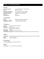
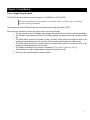
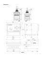
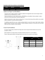
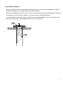
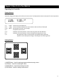
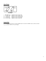
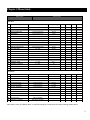
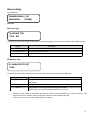
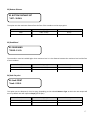
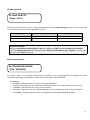
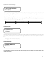
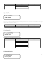
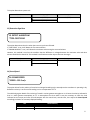
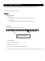
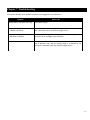
FLOMOTION FM1100 Ultrasonic Level Monitor USER’S MANUAL March 1, 2013 2 Ultrasonic Level Monitor FM1100 Series USER’S MANUAL 3 FLOMOTION SYSTEMS, INC. FM1100 SERIES COPYRIGHT © FLOMOTION SYSTEMS, INC. All rights reserved. No part of this publication may be reproduced, transmitted, transcribed, stored in a retrieval system, or translated into any language in any form without the written permission of FLOMOTION SYSTEMS, INC. WARRANTY AND LIABILITY FLOMOTION SYSTEMS, INC. guarantees for a period of 1 year from the date of delivery that it will either exchange or repair any part of this product returned to FLOMOTION SYSTEMS, INC. if it is found to be defective in material or workmanship, subject to the defect not being due to unfair wear and tear, misuse, modification or alteration, accident, misapplication or negligence. DISCLAIMER FLOMOTION SYSTEMS neither gives nor implies any process guarantee for this product, and shall have no liability in respect of any loss, injury or damage whatsoever arising out of the application or use of any product or circuit described herein. Every effort has been made to ensure accuracy of this documentation, but FLOMOTION SYSTEMS cannot be held liable for any errors. TECHNICAL ENQUIRIES Please contact FLOMOTION SYSTEMS, INC. for technical support FLOMOTION SYSTEMS Inc. www.FlomotionSystems.com 165 Creekside Dr., Suite # 112 Buffalo NY 14228 Tel:800-909-3569 (U.S. & Canada) or 716-691-3941 Fax:716-691-1253 E-Mail: [email protected] 4 Contents CONTENTS .......................................................................................................................................................................... 5 CHAPTER 1 INTRODUCTION ........................................................................................................................................................................6 About the FLOMOTION FM1100.........................................................................................................................................................6 Features.................................................................................................................................................................................................6 CHAPTER 2 PRODUCT SPECIFICATION .........................................................................................................................................................7 Physical.................................................................................................................................................................................................7 Environmental.......................................................................................................................................................................................7 Performance..........................................................................................................................................................................................7 Outputs..................................................................................................................................................................................................7 Programming........................................................................................................................................................................................7 Supply....................................................................................................................................................................................................7 CHAPTER 3 INSTALLATION .........................................................................................................................................................................8 Power Supply Requirements.................................................................................................................................................................8 Dimensions............................................................................................................................................................................................9 Terminal Connection...........................................................................................................................................................................10 Terminal Functions.............................................................................................................................................................................10 Outdoor and Open Vessel Installation................................................................................................................................................11 Closed Vessel Installation....................................................................................................................................................................11 Stand Pipe Installation........................................................................................................................................................................12 CHAPTER 4 HOW TO USE THE FM1100...................................................................................................................................................13 Operating the Controller.....................................................................................................................................................................13 CHAPTER 5 MENU GUIDE .........................................................................................................................................................................15 CHAPTER 6 DIGITAL COMMUNICATION .....................................................................................................................................................29 CHAPTER 7 TROUBLESHOOTING ...............................................................................................................................................................30 5 Chapter 1 Introduction About the FLOMOTION FM1100 The FLOMOTION FM1100 with sensor provides non-contacting level measurement for a wide variety of applications in both liquids and solids. The FM1100 system is comprised of an ultrasonic sensor and remote mounted controller that can be mounted up to 650 feet away from the level sensor. Easy calibration and maintenance-free performance means you can install the FM1100 rapidly and with confidence. The FLOMOTION FM1100 is ideally suited for a wide range of measurement applications such as wastewater pump stations, wet wells, ponds/reservoirs and chemical storage tanks. Features Programmable analog output Menu driven programming 5 SPDT relays for alarms and external control RS485 or RS232C (Optional) Weather resistant and safe against submersion (NEMA 6) Automatic temperature compensation 6 Chapter 2 Product Specification Physical Controller Dimensions Weight S260 Sensor Dimensions S400 Sensor Dimensions Sensor cable length Mounting Sensor material 9.45” (240mm) width x 7.3” (185mm) height Nominal 6.6 lb (3kg) 2.6” (67mm) dia x 5.2” (131mm) height 3.3 (82mm) dia x 5.9” (152mm) height 33ft (10m) Std., Up to 650ft max. 1”NPT Polypropylene Environmental Rating Temperature – Controller Temperature – Sensor NEMA 6 (Sensor), NEMA 4X (Controller) -4 ºF to +140 ºF (-20 ºC to +60 ºC) -4 ºF to +158 ºF (-20 ºC to +70 ºC) Performance Accuracy 0.2% of the measured range (S260) Resolution 0.04” (1mm) Range (Liquids) S260: 1.2ft (0.35m) to 26ft (8m) S400: 1.6ft (0.5m) to 40ft (12m) Beam Angle 8o at -3dB Damping Rate Adjustable from 0.1m/min to 100m/min Temperature Compensation Fully compensated via integral temperature sensor over entire operational span Outputs Analog output Display Relays 4-20mA into Max 750 (user adjustable) Fault condition Alarm 3.8mA or 21mA user selectable. 2 Line 40 Characters LCD 5 SPDT, 5A, 250VAC Programming On-board programming 4 tactile push button keys Supply Power supply AC 110 ~ 230VAC, DC 20-30VDC (opt) 7 Chapter 3 Installation Power Supply Requirements The FM1100 Series operates from an AC supply of 110-230VAC or DC 20-30VDC. All electronic products are susceptible to electrostatic shock, so follow proper grounding procedures during installation. The construction of the FM1100 Series can be mounted easily using the thread (1”NPT). When choosing a location to mount the sensor, bear in mind the following: For easy access to the LCD display and programming buttons mount it where it is easily accessible. The ultrasonic signal path should be free of falling material and obstructions such as pipes, beams etc. The S260 sensor should be mounted at least 14 inches (35cm) above the maximum level of the material and be perpendicular to the surface. The mounting surface should be vibration-free. The S400 sensor should be mounted at least 19 inches (50cm) above the maximum level of the material and be perpendicular to the surface. The ambient temperature of the sensor is between -4 ºF to +158 ºF (-20 ºC to +70 ºC). There should be no high voltage cables or electrical inverters close by. Do not use any metal substances when installing. 8 Dimensions S400 S260 FM1100 9 Terminal Connection Input & Output Terminals Rd Wh Blk Sensor Terminal Functions Terminal Function Note VCC 1 Connect to positive wire(red) of ultrasonic sensor SIG 2 Connect to shield wire(white) of ultrasonic sensor GND 3 Connect to shield wire(black) of ultrasonic sensor mA+ 4 4~20mA current output mA- 5 Current output return TX 6 RS232C interface in use, connect to reception part RS485 interface in use, connect to Y OPTION RX 7 RS232C interface in use, connect to transmission part RS485 interface in use, connect to Z OPTION GND 8 GROUND, RX, TX RLY4_NO 9 Lower limit relay point, OFF with LL_COM together in operation RLY4_COM 10 Lower limit relay point, OFF with LL_NO together in operation RLY4_NC 11 Lower limit relay point, OFF with LL_COM together out of operation RLY3_NO 12 Lower Alarm relay point, OFF with L_COM together in operation RLY3_COM 13 Lower Alarm relay point, OFF with L_NO together in operation RLY3_NC 14 Lower Alarm relay point, OFF with L_COM together out of operation RLY2_NO 15 Upper Alarm relay point, OFF with H_COM together in operation RLY2_COM 16 Upper Alarm relay point, OFF with H_NO together in operation RLY2_NC 17 Upper Alarm relay point, OFF with H_COM together out of operation RLY1_NO 18 Upper limit relay point, OFF with HH_COM together in operation RLY1_COM 19 Upper limit relay point, OFF with HH_NO together in operation RLY1_NC 20 Upper limit relay point, OFF with HH_COM together out of operation ER_NO 21 Error relay point, OFF with ER_COM together in operation ER_COM 22 Error relay point, OFF with ER_NO together in operation L2 23 Connect to line of AC power L1 24 Connect to line of AC power 25 Ground Maximum :750 Option: DC ver. 10 Quantity of cable hubs provided and cable thickness Model PG11 PG13.5 Quantity Diameter (ø) 4 1 0.20 ~ 0.39” (5~10mm) 0.24 ~ 0.47” (6~12mm) Outdoor and Open Vessel Installation The sensor can be simply mounted on a bracket, suitable for the application and secured using the thread located at the top of the transducer (1” NPT). Care should be taken to ensure that the sensors S260/S400 are not installed in direct sunlight, in order to avoid errors in the measurement of ambient temperature. Attention should also be taken, when mounting the unit, to ensure that strong windy conditions are avoided, wherever possible, to prevent abnormal operation. If conditions require that you use a metal mounting bracket to mount the sensor install rubber isolating gaskets between the sensor and the bracket to isolate mechanical vibrations in the bracket from the sensor which may cause unstable or erratic readings. Closed Vessel Installation The sensor can be simply screwed into a flange and secured using the thread located at the top of the transducer (1”NPT). Where possible use a flange made of a synthetic material such as PVC, to avoid vibration. Place a rubber gasket between the flange and the connection to the vessel to avoid vibration. Maximum Length S260 S400 3” (80mm) 7.2” (180mm) - 3.5” (100mm) 9.1” (230mm) 9.1” (230mm) 6” (150mm) 13.8” (350mm) 13.8” (350mm) 8” (200mm) 18.5” (470mm) 18.5” (470mm) Dia. 11 Stand Pipe Installation When mounting the sensor to a standpipe care should be taken to ensure that the standpipe is of sufficient diameter with reference to its length, see the table below for details: When using a standpipe, fixed to the top of a vessel, ensure that the open end of the standpipe is clear of any obstructions such as weld seams, gaskets etc. in order to avoid unwanted signal returns. If using standpipes, which extend into the vessel, beyond the blanking distance, but not as far as the empty level, then the open end of the standpipe should be cut to an angle of 45o. 12 Chapter 4 How To Use The FM1100 Operating the Controller Display Window FM1100 is designed to display various data at the same time. The display below shows an example of a normal operation. L: 6.44ft M: 80.5% 1) 2) 3) 4) 5) 6) 7) L: D: M: T: D: T: S: D: 1.56ft D T T: +24.5 ˚C 6.44ft: shows the current liquid level 1.56ft: shows the distance between the sensor bottom and the surface of the liquid. 80.5%: Percentage of the level in the storage. Temperature at the sensor. Indication of normal operation, shows returning echoes are well detected. Indication of normal operation, shows tracking of returning echoes is okay. No appearance under normal operation, but appears during abnormal operation such as abrupt level change. Searching for the returning echoes. Setting Buttons 1) MODE Button : Used for entering program mode and saving values.. 2) UP Button : Used for increasing the value. 3) DOWN Button : Used for decreasing the value. 4) RUN Button : Used for starting measurement. 13 Alarm Display 1) HH LED Lamp : Lighted in case of upper limit 2) H LED Lamp : 3) L LED Lamp : 4) LL LED Lamp : Lighted in case of upper alarm Lighted in case of lower alarm Lighted in case of lower limit Program Mode To enter programming mode press the the MODE button. Use the UP or DOWN arrows to make a selection. Press the MODE button to save your changes. 14 Chapter 5 Menu Guide Option Details Entered Value Main Menu No . 00 Description SENSOR TYPE 01 MEASURE TYPE 02 03 Range Factory Settings 8M/12M/15M 8M LEVEL / DISTANCE / SPACE LEVEL BOTTOM DISTANCE 0.00~26.0 ft (40.0 ft) 26.24 ft DEAD BAND 0.00~0.98 ft (1.47 ft) 0.98 ft 04 4mA POINT 0.00~26 ft (40 ft) 0.00 ft 05 20mA POINT 0.00~26 ft (40 ft) 26 ft 06 TRANSMIT POWER 1 ~ 5 (weak // strong) 3 (NORMAL) 07 DETECT THRESHOLD 08 DAMPING RATE 09 ERROR CURRENT SET 10 FAIL SAFE TIME 11 mA OUTPUT TEST 12 DISTANCE UNIT 13 DETECT ALGORISM 14 4 ~ 15 2 3 4 6 (0.6V) 0.01 ~ 100.0 m/min 1 (NORMAL) 3.8mA / Hold / 21.0mA 3.8 mA 20 ~ 999 300 sec HOLD / 3.8 / 4 / 12 / 20 / 21mA HOLD m(METER) / ft(FEET) Ft (FEET) FIRST ECHO / MAX ECHO FIRST ECHO SOUND SPEED 0 ~ 999 331.5 m/s 15 SPEED FACTOR 0 ~ 999 0.60m/ ℃ 16 MATERIAL TEMP 0 ~ 999 25.0 ℃ 17 MATERIAL T. WEIGHT 0 ~ 100% 0% 18 PASSWORD CHANGE 0 ~ 999 0 19 MASTER RESET - 1 - Relay Menu 01 RLY1(HH) ON POINT 0.00~26 ft (40 ft) 26.24 Ft 02 RLY1(HH) OFF POINT 0.00~26 ft (40 ft) 13.12 Ft 03 RLY2(H) ON POINT 0.00~26 ft (40 ft) 26.24 Ft 04 RLY2(H) OFF POINT 0.00~26 ft (40 ft) 13.12 Ft 05 RLY3(L) ON POINT 0.00~26 ft (40 ft) 26.24 Ft 06 RLY3(L) OFF POINT 0.00~26 ft (40 ft) 13.12 Ft 07 RLY4(LL) ON POINT 0.00~26 ft (40 ft) 26.24 Ft 08 RLY4(LL) OFF POINT 0.00~26 ft (40 ft) 13.12 Ft 09 RLY1 TOGGLE RELAY1 ON/OFF - 10 RLY2 TOGGLE RELAY2 ON/OFF - 11 RLY3 TOGGLE RELAY3 ON/OFF - 12 RLY4 TOGGLE RELAY4 ON/OFF - 13 ERROR RLY TOGGLE ERR RELAY ON/OFF - Note: When menu 19 “Master Reset” is used the settings are returned to the Factory Settings shown above. 15 Menu settings Press MODE key COMMON MENU: [ UP] RELAY MENU: [DOWN] Select UP 00) Sensor Type 00. SENSOR TYPE *TYPE – 8M This option sets the sensor range. According to the measuring range, the sensor can be selected in three different kinds. Option 8m (S260 Sensor) Description Measuring range up to 26 feet 12m (S400 Sensor) Measuring range up to 40 feet 15m (not used) 01) Measure Type 01. MEASURE TYPE SET *LEVEL This option sets the mode of operation when in run mode, and can be set to one of the following: Option Level Distance Space - Description Display shows how full the vessel is with respect to the Empty (0% of Span) Span) Display shows the distance from the transducer face to the surface. Display shows how an empty vessel is with respect to Full (100% of Span) i.e. how much space is available in the vessel. According to the choice of the option, the distance set point can be changed by the current output or relay output so that if the measure mode is changed, the distance value should be set again. From here the instruction is given based on the Level option. 16 02) Bottom Distance 02. BOTTOM DISTANCE SET * BOT : 26.24 ft This option sets the maximum distance from the face of the transducer to the empty point. Transducer Setting range Factory set S260 0.98 – 27.9 ft 26.2 ft S400 1.47 – 41.0 ft 33.4 ft 03) Dead Band 03. DEAD BAND *DEAD: 1.14 ft The transducer must be installed higher than maximum level. It is the distance between the maximum level and the face of the transducer. Transducer Setting range Factory set S260 0.98 – 27.9 ft 1.14 ft S400 1.47 – 41.0 ft 1.47 ft 04) 4mA Set point 04. 4mA POINT *4mA : 0.00 ft This option sets the distance (or level or space, depending on the selected Measure Type at which the 4mA output will occur. By default 4mA will represent Empty (0% of Span). Transducer Setting range Factory set S260 0 – 27.9 ft 0.00ft S400 0 – 41.0 ft 0.00ft 17 05) 20mA Set point 05. 20mA POINT SET *20mA : 26.0 ft This option sets the distance (or level or space, depending on the selected Measure Type at which the 20mA output will occur. By default 20mA will represent Full (100% of Span) Transducer Setting range Factory set S260 0 – 27.9 ft 26.2 ft S400 0 – 41.0 ft 33.4 ft Important Information The Span is the maximum working distance from Empty (0%) to full (100%), and is automatically calculated as Empty Level (Bottom Distance) minus Blanking Distance. Except for when Measure type = Distance in this case the Span is the same as the Empty Level 06) Transmitting Power 06. TRANSMITTING POWER *POW : 3(NORMAL) This option is used to set the power output from the transducer to suit varying applications. By reducing the power emitted the beam angle will be effectively reduced and can be applied as detailed below; - Setting Range: 1 (V WEAK) = Minimum Power (For use on short range applications) 2 (WEAK) = Low Power (For use on applications where obstructions such as pipes, beams, etc. are present) 3 (NORMAL) = Normal Power (For use in normal condition) 4 (STRONG) = High Power (For use in difficult applications where conditions are dusty, steamy or turbulent) 5 (V STRONG) = Maximum Power (For use in the applications to be expected diffused reflection) 18 07) Detection Threshold Voltage 07. DETECTION THRESHOLD *LEV : 1 (0.1V) This is an option for setting threshold for detection of the reflected wave. This option determines the detectable size of the return echo. This is useful when the first return echo is mixed in with echoes from smaller objects or obstructions located near the path of the sound wave. To reduce the probability of false detection or at an environment generating lots of noise, increase the threshold value. For detection of weak signals, decrease the value. In this way, set the threshold value according to the environmental conditions. The default value is 6. (Setting range: 4 – 15) Transducer Setting range Factory set S260/S400 1(0.1V) -15(1.5V) 1 08) Damping Rate 08. DAMPING RATE *1.0 m/min This option determines the maximum rate at which the unit will respond to an increase/decrease in level. Lower values give a slower, smoother response to variations in level. Higher values cause the meter to react quicker to variations in level. - Setting Range: 0.01 ~ 100.m/min (step:0.01) 09) Error Current Set 09. ERROR CURRENT SET *SET: 3.8mA If the S260/S400 fails to receive a valid echo return from the target, then the mA output can be used to indicate a fault condition (Lost of Echo) 19 Transducer Setting option Factory set S260/S400 3.8mA 3.8mA HOLD 21.0mA 10) Fail Safe Time 10. FAIL SAFE TIME *TIME: 300 sec In the event of a fail-safe condition occurring (Lost of Echo) the fail safe timer determines the time before the mA output indicates a fault condition (Lost of Echo) Transducer Setting range Factory set S260/S400 20 - 999 300 11) mA Output Test 11. mA OUTPUT TEST *OUTPUT: HOLD This option is used with other equipments for testing. Transducer Setting range S260/S400 HOLD (Current output) Factory set HOLD 4mA 12 mA 20 mA 3.8 mA 21 mA 12) Distance Unit Setting 12. DISTANCE UNIT *UNIT: Ft (FEET) 20 This option determines system unit Transducer Setting range Factory set S260/S400 M(METER) Ft(FEET) Ft(FEET) 13) Detection Algorithm 13. DETECT ALGORITHM *TYPE: FIRST ECHO This option determines the echo when there are many echoes reflected. If “FIRST ECHO” is set, it will detect the first returned echo. If “MAXIMUM ECHO” is set, it will detect the maximum echo among the returned echoes. However, this method is used on the condition that the difference in voltage between the maximum echo and other echoes should be less than 0.5V. This method is useful where smaller objects are near the target. Transducer Setting range Factory set S260/S400 FIRST ECHO FIRST ECHO MAX ECHO 14) Sound Speed 14. SOUND SPEED *SPEED : 331.5 m/s This option allows for the velocity of sound to be changed according to the atmosphere the transducer is operating in. By default the velocity is set for sound traveling in air at a temperature of 0 oC. The table below gives details of the velocity of sound in various gaseous atmospheres. In all cases the velocity indicated is that in a 100% gaseous atmosphere at 0 oC. In atmospheres less than 100% it may be necessary to check the level indicated at near empty and near full and compare with the actual level, several times, then adjust the Sound Speed accordingly to obtain an accurately displayed reading. Gas Chlorine Carbon Dioxide. Sound Velocity 206 m/sec 259 m/sec 21 Argon Oxygen Air Ammonia Methane Helium Neon 308 m/sec 316 m/sec 331.5 m/sec 415 m/sec 430 m/sec 435 m/sec 965 m/sec 15) Speed Factor 15. SPEED FACTOR *FACTOR : 0.60m/C The sound speed in air increases or decreases at fixed rate (0.6m/ ℃). This option allows the rate of change in m/C to be set according to the present atmosphere and temperature. This option is useful where ambiguous or mixed gas exists. The newly set value should be compared with the actual level, several times, to obtain an accurately displayed reading. - Setting Range : -2.0m/ °C ~ 2.0m/ °C 16) Material Temperature The S260/S400 uses an internal temperature sensor, housed inside the transducer nose cone and therefore the temperature used for compensation is the temperature close to sensor. In applications where there is a large difference between the temperature near the sensor and that at the surface of the material being measured, errors in measurement may occur. This mode allows for the present temperature at the material surface to be entered and reduces any error in measurement. 16. MATERIAL TEMP *TEMP : 25.0C Setting Range: 0~70.0C 17) Material Temperature Weighting This option is used in conjunction with Mode 16, Material Temperature. This option determines the effect the material 17. MATERIAL T WEIGHTING temperature has on the air temperature in front of the transducer. Where the temperature of the material has no effect on the air *WET : 0% temperature. Mode 17 should be set to 0, in which case Mode 16, Material Temperature will be ignored. However in cases where the material temperature heavily influences the temperature at the transducer Mode 17 should be set to 100 and 22 temperature compensation will be performed accordingly. - Setting Range: 0~100 18) Password Change 18. PASSWORD CHANGE *PASSWORD: 0 This option allows changing the password. The factory password set is “0”. The available number is “0” to “999”. If the password is forgotten, please request to the manufacturer. 19) Master Reset 19. MASTER RESET *RESET This option makes all setting value into the factory setting value. If this option is applied, all setting values are reset. Before reset, pay attention to note the current setting values for the reference. Select Reset with “mode” key, after showing “*” press “up” or “down” key. When [Run] shows, press “Run” key, all setting values are reset. 19. MASTER RESET *RESET [RUN] 23 Relay menu setting Press MODE key COMMON MENU: [ UP] RELAY MENU: [DOWN] Select DOWN ==== RELAY MENU ==== 01. ALT. RELAY SET 02. FIXED RELAY SET 03. RELAYS TEST 01. ALT. RELAY SET – NONE – Not Used at this time. 02. FIXED RELAY SET 1) RLY1(HH) Point Setting 02. FIXED RELAY SET *(1) R1 ON : 4.03f This option determines the high limit “ON” point for HH relay Transducer Setting range Factory set S260 0 – 27.9 ft 26.25 ft S400 0 – 41.0 ft 39.37 ft 24 2) RLY1(HH) OFF Point Setting 02. FIXED RELAY SET *(2) R1 OFF : 2.29f This option determines the high limit “OFF” point for HH relay Transducer Setting range Factory set S260 0 – 27.9 ft 13.12 ft S400 0 – 41.0 ft 19.69 ft 3) RLY2(H) ON Point Setting 02. FIXED RELAY SET *(3) R2 ON : 26.24f This option determines the “ON” point for H switched output Transducer Setting range Factory set S260 0 – 27.9 ft 26.25 ft S400 0 – 41.0 ft 39.37 ft 4) RLY2(H) OFF Point Setting 02. FIXED RELAY SET *(4) R2 OFF : 12.13f This option determines the “OFF” point for H switched output Transducer Setting range Factory set S260 0 – 27.9 ft 13.12 ft S400 0 – 41.0 ft 19.69 ft 25 5)RLY3(L) ON Point Setting 02. FIXED RELAY SET *(5) R3 ON : 26.24f This option determines the “ON” point for L switched output Transducer Setting range Factory set S260 0 – 27.9 ft 9.84 ft S400 0 – 41.0 ft 39.37 ft 6) RLY3(L) OFF Point Setting 02. FIXED RELAY SET *(6) R3 OFF : 13.12f This option determines the “ OFF” point for L switched output Transducer Setting range Factory set S260 0 – 27.9 ft 13.12 ft S400 0 – 41.0 ft 19.69 ft 7) RLY4(LL) ON Point Setting 02. FIXED RELAY SET *(7) R4 ON : 26.24f This option determines the low limit “ON” point for LL relay Transducer Setting range Factory set S260 0 – 27.9 ft 26.25 ft S400 0 – 41.0 ft 39.37 ft 26 8)RLY4( LL) OFF Point Setting 02. FIXED RELAY SET *(8) R4 OFF : 13.12f This option determines the low limit “OFF” point for LL relay Transducer Setting range Factory set S260 0 – 27.9 ft 13.12 ft S400 0 – 41.0 ft 19.69 ft 03. RELAYS TEST *(1) RLY1: From menu 09 to menu13 determines the relay on/off tentatively for the relay test. 03. RELAYS TEST 1)RELAY1 TOGGLE 2)RELAY2 TOGGLE 03. RELAYS TEST *(2) RLY2: 3)RELAY3 TOGGLE 03. RELAYS TEST *(3) RLY3: 4)RELAY4 TOGGLE 03. RELAYS TEST *(4) RLY4: 27 5)ERROR RELAY TOGGLE 03. RELAYS TEST *(5) ERROR: Important Information The value of HH relay ON point should be higher than OFF point and this function is used for high limit. The value of LL relay ON point should be lower than OFF point and this function is used for low limit H, L relay are used for pump control, draining control, high and low liquid level warning, etc. at user’s need. 28 Chapter 6 Digital Communication The FM1100 Series provides RS232/485 digital communication interface function as option The kinds of data and its format are as follows; Output Data 1. Kinds of Output Data 1) Distance Data - Distance from the sensor to the surface of measuring material. Unit is mm 2) Temperature Data - This is temperature data measured by built-in temperature sensor. Unit is 1°C 2. Data Format Data is edited by ASCII and the sequence as follows CR LF D T 10000 1000 100 10 1 +, - NULL 10 1 Temperature Data D: Distance data. L: Level data S: Space data E: Error occurs A. Baud Rate is 4800bps B. 1 Data Frame consists of Total 13byte C. Data Frame outputs per second D. The number located at 10000 means 10000mm digit number E. +/- means above/below zero in temperature. The number located at 10 means 10 degree digit number in °C/°F 29 Chapter 7 Troubleshooting This section describes some problem symptoms, with suggestions as to what to do. Symptom What to Do Display blank, transducer not firing. Check power supply Display shows “S”, “ ERROR! LOST ECHO” “S” means there is an abrupt liquid change or an obstacle in the beam path is detected. Check the obstacle and get rid of it. Display shows “ BOTTOM SET ERROR”. Measuring range is bigger than setting data of maximum range. Go to 03, and set the bigger bottom distance LE blink Check the sensor installation on the suitable place and whether the dept of bottom is over than the setting range or an obstacle in the beam path is detected. Check the obstacle and get rid of it. 30


![SP AF 28-105mm F/2.8 LD Aspherical [IF] (Model 176A)](http://vs1.manualzilla.com/store/data/005740924_1-d061f049cd68a1b27fa9e7b373db24a2-150x150.png)