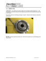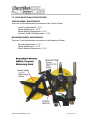
1
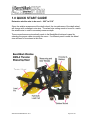
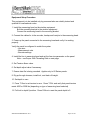
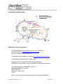
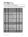
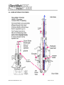
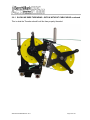
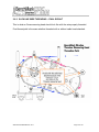
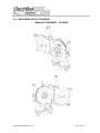
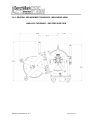
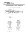
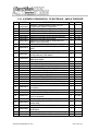
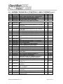
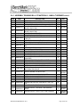
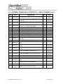
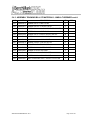
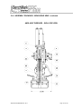
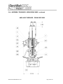
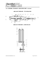
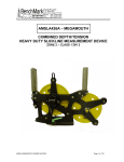
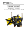
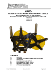
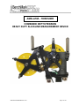
AMSLA595 - THRESHER COMBINED DEPTH/TENSION HEAVY DUTY SLICKLINE MEASUREMENT DEVICE AMSLA595 THRESHER OCT 2013 Page 1 of 136 SAFETY WARNINGS This apparatus is suitable for use in ATEX Zone 2 Locations. This apparatus is suitable for use in Class I, Division 2, Groups A, B, C, & D Hazardous (Classified) or Unclassified Locations. WARNING – EXPLOSION HAZARD – SUBSTITUTION OF COMPONENTS MAY IMPAIR SUITABILITY FOR ATEX Zone 2 LOCATIONS. AVERTISSEMENT – RISQUE D’EXPLOSION – LA SUBSTITUTION DE COMPOSANT PEUT RENDRE CE MATERIEL INACCEPTABLE POUR LES ATEX Zone 2 LOCALES. WARNING - EXPLOSION HAZARD – SUBSTITUTION OF COMPONENTS MAY IMPAIR SUITABILITY FOR CLASS I, DIVISION 2; AVERTISSEMENT - RISQUE D'EXPLOSION – LA SUBSTITUTION DE COMPOSANTS PEUT RENDRE CE MATERIEL INACCEPTABLE POUR LES EMPLACEMENTS DE CLASSE I, DIVISION 2 WARNING – EXPLOSION HAZARD – DO NOT DISCONNECT EQUIPMENT UNLESS POWER HAS BEEN SWITCHED OFF OR THE AREA IS KNOW TO BE NONHAZAROUS; AVERTISSEMENT – RISQUE D’EXPLOSION – AVANT DE DECONNECTER L’EQUIPMENT, COUPER LE COURANT OU S’ASSURER QUE L’EMPLACEMENT EST DESIGNE NON DANGEREUX. WARNING - PROTECTION MAY BE IMPAIRED IF THIS DEVICE IS USED IN AN APPLICATION OR MANNER NOT SPECIFIED IN THE MANUAL NOTE – The safe ambient temperature operating range for this equipment is -20 to 40C or -4 to 104F. ___________________________________________________ BenchMark measuring equipment will frequently be operated in hazardous environments. Appropriate safety precautions need to be taken. Training - Operators shall be trained in the proper and safe use of the device. Do not exceed the tension limit specified for this device in this manual. AMSLA595 THRESHER OCT 2013 Page 2 of 136 SAFETY WARNINGS continued Flammable Substances - Flammable and explosive substances are often found in the proximity of the equipment operations. Proper venting should take place where practicable. Avoid open flames, sparks and other ignition sources. Electric Shock – Depending on the equipment being used, both AC and DC current may be present. Frequently in wellsite operations conductive fluids and chemicals are used. Use extra caution when working with BenchMark equipment and follow manufacturer warnings to avoid electric shock. Do not separate any electrical connector, while powered, in a hazardous area. Separate only when power is removed, and/or in a safe area. Safe Operating Temperatures – BenchMark Wireline equipment is designed to operate safely within these temperature ranges. Do not try to operate this equipment in conditions that outside these temperature limits. The safe ambient temperature operating range for this equipment is -20 to 40C or -4 to 104F. Hazardous Equipment Marking - See General Assembly drawings for hazardous equipment marking. ALL WARNING LABELS ON THE EQUIPMENT MUST BE OBSERVED AND FOLLOWED. Installation Instructions - Install measuring device onto the spooling mechanism per the unit manufacturer instructions. Take care to avoid pinching or cutting of electrical cables when the measuring device moves during the spooling operation. Take care to thread the wire through the device properly to prevent the wire from rubbing the frame during operation. The Table of Contents of this manual will list where the threading procedure is located. Rotating Equipment – BenchMark Wireline measuring equipment is often attached to rotating industrial machinery. This may include winches, pulleys, rigging, rotating drums plus moving cable and wire. Though BenchMark’s measuring equipment does not normally present a safety hazard when in operation provided it is used within the design parameters of the equipment, the heavy equipment used in this type of work in proximity to BenchMark’s equipment may. Never attempt to use BenchMark equipment in any way or for any other purpose than for which it was designed. Use every precaution to keep a safe distance from dangerous equipment when it is in operation. Never approach the measuring device while the cable drum is turning. AMSLA595 THRESHER OCT 2013 Page 3 of 136 CONTENTS 1.0 QUICK START GUIDE 2.0 GENERAL DESCRIPTION & FEATURES 1.1 Product description & intended use of equipment 1.2 Safety standards & ATEX requirements 1.3 Type examination certificates 1.4 Technical specifications 1.5 Hardware features 1.6 User interface features - Wire Threading 1.7 Hazardous area installation standards & requirements 1.8 Obtaining Technical Assistance 3.0 SOFTWARE OPERATING INSTRUCTIONS 4.0 SOFTWARE UPDATE PROCEDURES 5.0 MAINTENANCE, ASSEMBLY DRAWINGS & PARTS LIST 5.1.2 Lubrication 5.2.1 Tension wheel - Load Pin replacement 5.2.2 Tension wheel - Wheel Replacement 5.2.3 Tension wheel - Bearing Replacement 5.2.4 Tension wheel – Load Cell replacement 5.3.1 Measuring wheel - Encoder Replacement 5.3.2 Measuring wheel - Wheel Replacement 5.3.3 Measuring wheel - Bearing Replacement 5.4.1 General Arrangement Parts Lists 5.4.2 General Arrangement Drawings 5.4.3 Assembly Bill of Materials AMSLA595 THRESHER OCT 2013 Page 4 of 136 CONTENTS continued 5.4.4 Assembly Drawings 5.4.5 Recommended Spare Parts 5.5 Load pins 5.6 Encoder 5.7 Optional Accessories 6.0 SCHEMATICS & WIRELISTS 7.0 CABLE DRAWINGS AMSLA595 THRESHER OCT 2013 Page 5 of 136 1.0 QUICK START GUIDE Determine wireline size to be used – .092" to 5/16” Since the wireline wraps around the depth wheel, the circumference of the depth wheel will change with a change in wire size. The wheel size setting needs to be set to match the wireline size in order to accurately measure depth. These corrections are automatically made in the BenchMark hoistman's panel by selecting the proper cable size using the menu. If a different panel is used, the wheel size will need to be entered at this time. AMSLA595 THRESHER OCT 2013 Page 6 of 136 Equipment Setup Procedure This equipment is to be installed only by personnel who are suitably trained and qualified to local/national codes. 1. Install the measuring head on the wireline equipment. Bolt the mounting bracket to the wireline equipment Connect the measuring head to the mounting bracket 2. Connect the cables for to the encoder, backup and load pin to the measuring head. 3. Power up the panel connected to the measuring head and verify it is working properly. Verify the panel is configured to match the system - Line size - Measurement units - Encoder settings 4. Install the line in measuring head and set the line size parameter on the panel. Note – see Proper Wire Threading Path on next page. 5. Set Tension Alarm value. 6. Set depth adjust value if necessary. 7. Ensure data file is being recorded. Applies only to 60 Series panels. 9. Rig up through sheaves, install tool, and slack off weight. 10. Set depth to zero. 11. Press T-Zero to set tension to zero. Press T-CAL and verify that panel tension reads 4000 or 5000 lbs (depending on type of measuring head selected) 12. Pull tool to depth 0 position. Press D-Zero to reset the panel depth to 0. AMSLA595 THRESHER OCT 2013 Page 7 of 136 Proper Wire Threading Path Obtaining Technical Assistance Call BenchMark Wireline Products Inc. at +1 281 346 4300 Or contact by email [email protected] Or fax in request at +1 281 346 4301 Information is also available on website www.benchmarkwireline.com Parts can be ordered by email, phone, or fax. Equipment can be returned for repair and maintenance. Please notify us by Phone, email, or fax before sending any equipment. To return equipment to BenchMark, ship it to: BenchMark Wireline Products 36220 FM 1093 Simonton, Texas 77476 U.S.A. Note – For better response, please have the Part Number available. AMSLA595 THRESHER OCT 2013 Page 8 of 136 Recommended Spare Parts List - AMSLA THRESHER This is a list of recommend spare parts. Normally you would stock the suggested QTY of spares. For REMOTE areas where resupply is difficult, use the REMOTE amounts. ITEM 1 2 4 12 13 P/N DESCRIPTION WHEEL MEASURING 4FT 0.092-1/4 WHEEL ASSY TENS 20" 5/16 MAKO ADAPTER ENCODER H25D/H20 MAG WHEEL ASSY PRESS RLR 1/4 TENSN WHEEL ASSY PRESS RLR 1/4 MEASR QTY 0 0 0 2 1 AMSLA560 AM3KM040 AMSLA162 AMSLA163 NOTE ‐ ONLY STOCK THE LOAD AXLE USED IN YOUR MEASURING HEAD REMOTE 1 1 1 2 2 20 AMSLA215A ASSY LOAD AXLE 4-20mA 1.50 DIA 15K# LINE PULL 2WIR Exn 0 1 20 AMSLA252A ASSY LOAD AXLE 2MV/V 1-1/2 Z2 P106P DUAL PASSIV 09ATEX41118 0 1 20 AMSLA253A ASSY LOAD AXLE 2MV/V 1-1/2 Z2 P106P PASSIVE 09ATEX41118 0 1 20 AMSLA272A ASSY LOAD AXLE 2MV/V 1-1/2 Z2 KP16-8P PASSIVE 09ATEX41118 0 1 20 AMSLA277A ASSY LOAD AXLE 2MV/V 1-1/2 Z2 MS14S 6P PASSIVE 09ATEX41118 0 1 20 AMSLA278A ASSY LOAD AXLE 2MV/V 1-1/2 Z2 CWL18 10P PASSIVE 09ATEX41118 0 1 20 AMSLA287A ASSY LOAD AXLE 2MV/V 1-1/2 Z2 CWL18 10P PASSIVE 09ATEX41118 0 1 20 AMSLA550B 0 1 21 AM3KM050 ASSY LOAD AXLE 0-1.5V 1-1/2DIA 015000# KPT16 8 PIN Exn COUPLING ENCDR W/BKUP MAGNETS 0 NOTE ‐ ONLY STOCK THE ENCODER USED IN YOUR MEASURING HEAD 49 49 AM5KA055 AM5KA058 50 AM5KA068B 50 AM5KA070B 50 ASSY ENCODER BACKUP MAGNETIC ASSY ENCDR BACKUP MAG EEx nA ASSY ENCDR 1200 PPR OPTICAL MS16 HES Ex nA ETL09ATEX41123 2 0 0 1 1 0 1 ASSY ENCDR 512/780 PPR OPTICAL KP14 Ex nA ETL09ATEX41123 0 1 AM5KA074B ASSY ENCDR 1200 PPR OPTICAL MS18 Ex nA ETL09ATEX41123 0 1 50 AM5KA079B ASSY ENCDR 1200 PPR OPTICAL MS16 STD Ex nA ETL09ATEX41123 0 1 50 AM5KA080B 0 1 51 52 53 54 AMS1P090 AMSLP040 AMSLP030 AM3KP204 1 1 1 2 2 2 2 2 ASSY ENCDR 1200 PPR OPTICAL MS16 BLUE Ex nA ETL09ATEX41123 COUPLING OLDHAM ENCODER BEARING SPHERE-ROL 50MM ID BEARING BALL 30MM 2-ROW SST BEARING BALL 20MM SST ABEC-1 AMSLA595 THRESHER OCT 2013 Page 9 of 136 2.0 GENERAL DESCRIPTION & FEATURES 2.1 PRODUCT DESCRIPTION & INTENDED USE OF EQUIPMENT The "Orca” Slickline Measuring Device is a heavy duty three wheeled device which accurately measures both wireline depth, line speed and tension. It minimizes wire abrasion and fatigue by using a non reverse bend configuration. The device is designed to be mounted in front of the wireline drum on a spooling mechanism. Linear bearings in the mount allow it to slide back and forth in front of the drum so the wire can be spooled evenly. The bracket on the top of the measuring head is used to mount it to the wireline unit. Spooling rollers and pressure wheels are provided to keep the wire in the wheels at low or no tension. This measuring head is different from previous versions in that the wireline can be removed from the measuring head without cutting off the re-head. The wireline can be removed from the side. The guide rollers are slotted so they can be slid out of the way to remove the wireline. Tension is measured from a load pin which also serves as the axle for the tension wheel. The Orca also has a hydraulic load cell which is an independent tension measuring device. Since the tension wheel is opposite the measuring and idler wheel, the wire completely wraps around both wheel sets. This creates a relatively high signal at the load pin which provides a very accurate tension measurement. With the BenchMark Winchman's Panel, depth can be accurately measured on different sized lines without changing wheels. This is done electronically by the panel using the depth information provided by an encoder. Changes in wire size are accounted for by the panel software. Wire stretch can also be automatically calculated by the panel. An adapter is provided to drive a standard mechanical counter. AMSLA595 THRESHER OCT 2013 Page 10 of 136 2.2 SAFETY STANDARDS & UL CLASS 1, DIVISION 2 REQUIREMENTS We have been evaluated and comply with these standards: UL Standard for Electrical Equipment for Measurement, Control, and Laboratory Use; Part 1: General Requirements (UL 61010-1, 2nd Ed., October 28, 2008) Standard for Safety Requirements for Electrical Equipment for Measurement, Control, and Laboratory Use; Part 1: General Requirements (CAN/CSA C22.2 No. 61010-1-04 (R2009)) Standard for Nonincendive Electrical Equipment For Use in Class 1 and 2, Division 2 and Class 3, Divisions 1 and 2 Hazardous (Classified) Locations (ANSI/ISA 12.12.01-2011) Standard for Non-Incendive Electrical Equipment For Use in Class 1, Division 2 Hazardous Locations (CSA C22.2 No. 213-M1987 (R2008)) AMSLA595 THRESHER OCT 2013 Page 11 of 136 2.3 TYPE EXAMINATION CERTIFICATES Certificates will go in this section. AMSLA595 THRESHER OCT 2013 Page 12 of 136 2.4 TECHNICAL SPECIFICATIONS 2.4.1 WIRE PATH The wire runs from the well around the measure wheel (wheel nearest drum) then around the tension wheel and back across the top of the idler wheel onto the drum. The tension wheel is tilted slightly with respect to the measuring wheel so that the wire enters the wheel on one side of the groove and exits the wheel on the opposite side of the groove. Guide rollers are aligned to assist in keeping the wire on the proper side of the groove. The wire runs through a non reversed bend configuration (i.e. the wire is always bent in the same direction). This minimizes wire fatigue which normally occurs by bending the wire in opposite directions each time it passes through the measuring head. The large wheel radius minimizes the effects of fatigue and promotes longer wire life, especially with larger diameter wirelines. Guide rollers are installed on the tension wheel to keep the wire in the groove. A spring mounted pressure roller is used on the measure wheel to ensure the wire is always pressed tightly against the measure wheel to prevent wire slippage at low tension which minimizes measurement error. The spring tightly presses the wire against the wheel regardless of wire size. The spring force keeps the wire turning the wheel even with sudden changes of direction during jarring action. A composite keeper roller is mounted above the measure wheel to keep the wire in the groove when wireline tension is relaxed such as during transport and rigup. AMSLA595 THRESHER OCT 2013 Page 13 of 136 2.4.2 DEPTH MEASUREMENT Depth measurement is made by wrapping the wire around the measuring wheel which has a precision machined groove. The wheel groove has a diameter of 20.06 inches. The wheel is hardened to greater than Rockwell 58 by using a special heat treat process. This minimizes wheel wear to maximize wheel life. This measuring head is capable of providing three completely independent depth measurements, a mechanical counter, an optical encoder, and a magnetic pickup. The optical encoder provides a high resolution measurement to the BenchMark Wireline Products hoistman’s panel. With this panel depth and line speed can be accurately measured on different sized lines without changing wheels. This is done electronically by the panel. Changes in wire size are accounted for by the panel software. Wire stretch can also be automatically calculated by the panel. The panel operates on 12-24 vdc and supplies the necessary power to the encoder and load pin. A backup depth system is available to provide another independent depth measurement. Depth is measured by a frictionless magnetic pickup mounted in the measuring head. The pickup consists of magnets imbedded in the measure wheel coupling and two hall affect devices mounted next to the shaft. This provides a quadarature type measurement. A small display panel is mounted inside a wireline unit. The panel is designed to be connected to an external AC or DC supply or operate off internal batteries for up to 15 hours between charges. In the event of an external power interruption, the unit automatically switches to battery power. The system is designed to operate without intervention from the user. When external power fails, the depth display is maintained by the batteries. A switch on the front of the panel allows different sizes of wire to be measured accurately without changing the measuring wheels. AMSLA595 THRESHER OCT 2013 Page 14 of 136 2.4.3 TENSION SPECIFICATIONS The wheel nearest the well rotates on an axle pin that is instrumented with strain gauges. These strain gauges produce an electrical signal proportional to the magnitude of line tension. The wire always makes a complete 180 degree wrap around the tension wheel so rigup angle does not affect the tension measurement. The tension wheel is mounted on a self aligning bearing which allows the wheel to properly align itself. This reduces any side forces that may be present which increases the tension measurement accuracy. Additionally, a hydraulic load cell is included which measures wireline tension independently of the electronic load pin. It is mounted in the frame and measures the tension differential between the measuring wheel and the tension wheel. 1. PASSIVE LOW VOLTAGE Power Requirement - 12 vdc excitation Interface – None – passive bridge only 2. DIFFERENTIAL VOLTAGE Power Requirements - +/– 15 vdc input power Interface - Proprietary circuit board which amplifies the load pin signals and provides a 1.5v differential output. 0 vdc = 0 lbs (0 kg) .75 vdc = 5,000 lbs (2,268) - shunt cal 1.5 vdc = 10,000 lbs (4,536 kg) AMSLA595 THRESHER OCT 2013 Page 15 of 136 2.4.3 TENSION SPECIFICATIONS continued 3. 4-20MA CURRENT LOOP Power Requirements - +24vdc input power Interface - Proprietary circuit board which amplifies the load pin signals and provides a 4-20ma current loop output. 4 ma 12 ma 20ma = 0 lbs (0 kg) = 5,000 lbs (2,268) - shunt cal = 10,000 lbs (4,536 kg) COMMON SPECIFICATIONS Temperature Stability <= .015% full scale / deg F on zero <= .02% full scale / deg F on output Accuracy 1% full scale nominal Maximum Rated Load 9,000 lbs AMSLA595 THRESHER OCT 2013 (4,082 kg) Page 16 of 136 2.4.4 GENERAL SPECIFICATIONS Height: 39.16” .994 m Width: 51.99” 1.320 m Depth: 12.79" .324 m Weight: 350 lbs 158.75 kg Maximum Tension: 15,000 lbs 6,803 kg Line Sizes: .092" – 5/16” 2.33 mm – 7.93 mm Encoder: 1,200 PPR , others available Backup Counter: 4 PPR Quadarature Load Pin: Passive low voltage Differential voltage 4-20ma current loop AMSLA595 THRESHER OCT 2013 Page 17 of 136 2.5 HARDWARE FEATURES Cable sizes .092 to .125 slickline & 3/16” to 5/16” e-line/braided line Tension load axle & amplifier can be configured to different outputs 3 fully independent depth measurements - 1. mechanical counter 2. optical encoder 3. magnetic pickup Backup depth system – reduces drag on measuring wheel by eliminating mechanical drive cable Encoder & tension amplifier certified for Zone II area use Anodized aluminum frame – all steel parts are plated or SST Line removal from the side without cutting off Cable Head Minimizes wire abrasion & fatigue by using non-reverse bend configuration Separate measuring and idler wheels completely eliminates wire rub Large diameter wheel radius minimize wire fatigue Spooling rollers and pressure wheels keep wire in wheel at low/no tension Sprung pressure wheel keeps wire turning with wheel even with sudden direction change or jarring action Top mount configuration on a 40mm overhead spooling bar Hydraulic Load Cell provides second independent tension measurement AMSLA595 THRESHER OCT 2013 Page 18 of 136 2.6 USER INTERFACE FEATURES AMSLA595 THRESHER OCT 2013 Page 19 of 136 2.6.1 SLICKLINE WIRE THREADING – WITH & WITHOUT CABLE HEAD The Thresher measuring head can be threaded either with or without the cable head attached. These images show a wire without a cable head but the same procedure can be used for a wire with the cable head attached by threading from the side and top around the rollers. Loosen the screws on both sets of guide rollers only if the cable head is attached. Swing the guide roller plate away leaving top access to the space between the guide rollers. Loosen the keeper roller, move it to the top of its slot and retighten the screw. AMSLA595 THRESHER OCT 2013 Page 20 of 136 2.6.1 SLICKLINE WIRE THREADING - WITH & WITHOUT CABLE HEAD continued Loosen the upper pressure roller, move it to the end of its slot and retighten the screw. Loosen the lower pressure roller, move it to the end of its slot and retighten the screw. AMSLA595 THRESHER OCT 2013 Page 21 of 136 2.6.1 SLICKLINE WIRE THREADING - WITH & WITHOUT CABLE HEAD continued Thread the wire between the 1st set of guide rollers then over the top of the idler wheel. The idler wheel is the one on the encoder side of the measuring head and lines up directly with the gap between the guide rollers. AMSLA595 THRESHER OCT 2013 Page 22 of 136 2.6.1 SLICKLINE WIRE THREADING - WITH & WITHOUT CABLE HEAD continued Feed the wire under the guide roller plate spacer. The wire then goes over the top of the tension wheel. AMSLA595 THRESHER OCT 2013 Page 23 of 136 2.6.1 SLICKLINE WIRE THREADING - WITH & WITHOUT CABLE HEAD continued It then goes around the back of the wheel under the upper pressure roller. It continues around the bottom of the wheel under the lower pressure roller. AMSLA595 THRESHER OCT 2013 Page 24 of 136 2.6.1 SLICKLINE WIRE THREADING - WITH & WITHOUT CABLE HEAD continued The wire now goes from the underside of the tension wheel to the underside of the measuring wheel, above the lower keeper roller. The measuring wheel is the one closed to you. Use a ¾” open end wrench to spring the pressure roller arm away from the measuring wheel and thread the wire between the pressure roller and the measuring wheel groove. AMSLA595 THRESHER OCT 2013 Page 25 of 136 2.6.1 SLICKLINE WIRE THREADING - WITH & WITHOUT CABLE HEAD continued Note – make sure that the wire is in the groove of the measuring wheel, (the one closest to you), and not the groove of the idler wheel. Now thread it over the top of the measuring wheel. Example – this is how the wire should look when properly threaded. AMSLA595 THRESHER OCT 2013 Page 26 of 136 2.6.1 SLICKLINE WIRE THREADING - WITH & WITHOUT CABLE HEAD continued Run the wire out through the gap between the other guide rollers. Now reposition the two keeper rollers and the two pressure rollers back in their slots and tighten the screws. Note – the two pressure roller need to be in the slot of the tension wheel. Avoid adjusting them with too heavy a contact with the tension wheel. If they are too close they can bind and give false reading. AMSLA595 THRESHER OCT 2013 Page 27 of 136 2.6.1 SLICKLINE WIRE THREADING - WITH & WITHOUT CABLE HEAD continued This is what the Thresher should look like then properly threaded. AMSLA595 THRESHER OCT 2013 Page 28 of 136 2.6.2 SLICKLINE WIRE THREADING – FINAL RESULT This is what an Orca measuring head should look like with the wire properly threaded. Final thread path is the same whether threaded with or without cable head attached. AMSLA595 THRESHER OCT 2013 Page 29 of 136 2.7 HAZARDOUS AREA INSTALLATION STANDARDS & REQUIREMENTS This equipment is to be installed only by personnel who are suitably trained and qualified to local/national codes. 1. Install the measuring head on the wireline equipment. Bolt the mounting bracket to the wireline equipment. Connect the measuring head to the mounting bracket. 2. Connect the cables from the panel to the encoder, backup and load pin on the measuring head. Make sure you use the correct cable for each connection as described in this manual. AMSLA595 THRESHER OCT 2013 Page 30 of 136 2.8 OBTAINING TECHNICAL ASSISTANCE Call BenchMark Wireline Products Inc. at +1 281 346 4300 Or contact by email [email protected] Or fax in request at +1 281 346 4301 Information is also available on website www.benchmarkwireline.com Parts can be ordered by email, phone, or fax. Equipment can be returned for repair and maintenance. Please notify us by Phone, email, or fax before sending any equipment. To return equipment to BenchMark, ship it to: BenchMark Wireline Products 36220 FM 1093 Simonton, Texas 77476 U.S.A. Note – For better response, please have the Part Number available. AMSLA595 THRESHER OCT 2013 Page 31 of 136 3.0 SOFTWARE OPERATING INSTRUCTIONS NOTE - The measuring heads do not contain any software. The software is in the display panel. A variety of display panels can be used with this measuring head. To view the Software Operating Instruction, refer to the manual for the Display Panel being used with this head. AMSLA595 THRESHER OCT 2013 Page 32 of 136 4.0 SOFTWARE UPDATE PROCEDURES NOTE - The measuring heads do not contain any software. The software is in the display panel. A variety of display panels can be used with this measuring head. To view the Software Update Procedures, refer to the manual for the Display Panel being used with this head. AMSLA595 THRESHER OCT 2013 Page 33 of 136 5.0 MAINTENANCE, ASSEMBLY DRAWINGS & PARTS LIST 5.1.1 PRE AND POST JOB CHECKS Between jobs, check the measuring and guide wheels for looseness, play, out-ofroundness, worn or rough sounding bearings, or other mechanical conditions that could affect measurement accuracy. Visually inspect the interiors of the electrical connectors for the encoders and electronic load axle for dirt and evidence of insulation breakdown. Clean or replace as necessary. Install dust caps on the connectors if the cables are removed. Manually rotate each wheel by hand to verify its condition. Inspect the depth measuring wheel for signs of abnormal wear diameter changes, or shaft play that can affect measurement accuracy. The wheel should be replaced if it is grooved more than .005". Inspect the tension wheels for signs of abnormal wear, diameter changes, or shaft and bearing play that could affect measurement accuracy. It should also be replaced if it is grooved more than .005". Do not pressure wash bearings or electrical parts AMSLA595 THRESHER OCT 2013 Page 34 of 136 5.1.2 LUBRICATION Lubrication – use waterproof marine grease and a straight necked grease gun. Use the grease nozzle that comes with the measuring head (in the small plastic bag zip-tied to the frame). Press the nozzle into the fitting and apply 3 squirts. Repeat same lubrication schedule each month. DO NOT pressure wash the machine as it will force the grease out of the bearings and they will fail. AMSLA595 THRESHER OCT 2013 Page 35 of 136 5.2 FIELD MAINTENANCE PROCEDURES TENSION WHEEL MAINTENANCE There are 3 field maintenance procedures for the Tension Wheel. - Load Pin Replacement – 5.2.1 - Wheel Replacement – 5.2.2 - Wheel Bearing Replacement – 5.2.3 - Hydraulic Load Cell Replacement – 5.2.4 MEASURING WHEEL MAINTENANCE There are 3 field maintenance procedures for the Measuring Wheel. - Encoder Replacement – 5.3.1 - Wheel Replacement – 5.3.2 - Wheel Bearing Replacement – 5.3.3 AMSLA595 THRESHER OCT 2013 Page 36 of 136 5.2.1 TENSION WHEEL - LOAD PIN REPLACEMENT The 1st step is to remove the spiral lock from the load pin shaft. If the lock has not been damaged it can be used again on reassembly. Hold the tension wheel with one hand. AMSLA595 THRESHER OCT 2013 Page 37 of 136 5.2.1 TENSION WHEEL - LOAD PIN REPLACEMENT continued Gently remove the load pin from the wheel hub. The load pin shaft holds the tension wheel in place. With the load pin removed gently let the tension wheel rest in the frame. Put anti-seize compound on shaft of the new load pin. AMSLA595 THRESHER OCT 2013 Page 38 of 136 5.2.1 TENSION WHEEL - LOAD PIN REPLACEMENT continued Position the tension wheel so that the load pin can be placed through the wheel hub. Note that the load pin has a flat notch on one side. AMSLA595 THRESHER OCT 2013 Page 39 of 136 5.2.1 TENSION WHEEL - LOAD PIN REPLACEMENT continued The flat side of the load pin will flange up to the guide plate on the frame. Insert the load pin and rotate it so that the flat side of the pin butts up to the guide plate. AMSLA595 THRESHER OCT 2013 Page 40 of 136 5.2.1 TENSION WHEEL - LOAD PIN REPLACEMENT continued The bushing in the tension wheel bearing has a slot for an anti rotation screw. *Note - depending on position of the wheel, if during this procedure the tension wheel stays in place, there is no need to remove the anti rotation screw. If the wheel moves too much, the bearing may slide off the anti-rotation screw. In that case you must remove the anti-rotation screw for proper reinstallation. AMSLA595 THRESHER OCT 2013 Page 41 of 136 5.2.1 TENSION WHEEL - LOAD PIN REPLACEMENT continued Spin the wheel until the anti rotation slot on the bearing can be seen through the anti rotation screw hole. Replace the anti rotation screw and tighten it firmly. AMSLA595 THRESHER OCT 2013 Page 42 of 136 5.2.1 TENSION WHEEL - LOAD PIN REPLACEMENT continued Replace the spiral lock. AMSLA595 THRESHER OCT 2013 Page 43 of 136 5.2.2 TENSION WHEEL - WHEEL REPLACEMENT For this maintenance, we assume that the load pin has been removed. 5.2.1 Loosen and completely move the pressure roller to the end of its slot and retighten. Pull the wheel up and out of the frame. If bearing replacement is needed see 5.2.3 Reposition the wheel back in the frame and follow the load pin installation instructions in 5.2.1. Then replace and adjust the pressure roller. AMSLA595 THRESHER OCT 2013 Page 44 of 136 5.2.3 TENSION WHEEL - BEARING REPLACEMENT For this maintenance, it is assumed that the tension wheel has been removed. The bearing is held in the wheel hub by 2 snap rings. Remove the rings and push the bearing out. An Arbor press is being used to demonstrate this replacement. AMSLA595 THRESHER OCT 2013 Page 45 of 136 5.2.3 TENSION WHEEL - BEARING REPLACEMENT continued An anti-rotation bushing will be pressed into the new bearing. Place the new bearing on the press. On the first stroke, the bushing may not go all the way into the bearing. Add a spacer on the bottom of the bearing as the bushing will protrude below the bottom bearing. AMSLA595 THRESHER OCT 2013 Page 46 of 136 5.2.3 TENSION WHEEL - BEARING REPLACEMENT continued The bushing is properly installed when approximately equal amounts stick out both above and below the bearing assembly. AMSLA595 THRESHER OCT 2013 Page 47 of 136 5.2.3 TENSION WHEEL - BEARING REPLACEMENT continued Take the Tension Wheel. 2 snap rings will hold the bearing assembly in place. The front of the wheel is the side with the grease fitting. On the BACK of the wheel, install the 1st snap ring. AMSLA595 THRESHER OCT 2013 Page 48 of 136 5.2.3 TENSION WHEEL - BEARING REPLACEMENT continued Then turn the wheel over. You should be able to simply insert the bearing assembly into the center hub. Install the 2nd snap ring to hold the bearing in place. AMSLA595 THRESHER OCT 2013 Page 49 of 136 5.2.3 TENSION WHEEL - BEARING REPLACEMENT continued Manually tug on the bearing assembly to make sure it is firmly in place. Lubrication – use waterproof marine grease and a straight necked grease gun. Use the grease nozzle that comes with the measuring head (in the small plastic bag zip-tied to the frame). Press the nozzle into the fitting and apply 3 squirts. Repeat same lubrication schedule each month. DO NOT pressure wash the machine as it will force the grease out of the bearings and they will fail. AMSLA595 THRESHER OCT 2013 Page 50 of 136 5.2.4 LOAD CELL REPLACEMENT The Thresher measuring head has a pivot joint that connects the measuring wheel assembly to the tension wheel assembly. The hydraulic load cell is placed between those two assemblies. Because of the circular wire path, as tension is added to the wire, it will pull the tension wheel assembly towards the measuring wheel thus exerting pressure on the load cell. The load cell is screwed to the measuring wheel side of the frame and it rests against a flat mounting plate on the tension wheel side. AMSLA595 THRESHER OCT 2013 Page 51 of 136 5.2.4 LOAD CELL REPLACEMENT continued The Hydraulic Load Cell is an additional tension measuring device independent of the load pin. To replace the load cell, two screws which run through the mounting plate up into the bottom of the load cell and a deeply recessed screw need to be removed. AMSLA595 THRESHER OCT 2013 Page 52 of 136 5.2.4 LOAD CELL REPLACEMENT continued First remove the recessed screw. For this task a ¼ inch drive with an 8 to 10 inch extension will work the best and a flexible connection on the extension is also helpful. The screw is accessed by putting the extension in the position shown “between the frame and the idler wheel” behind the encoder as shown in the picture. Then attach a ratchet to the extension, loosen and remove the screw and remove the extension and socket. AMSLA595 THRESHER OCT 2013 Page 53 of 136 5.2.4 LOAD CELL REPLACEMENT continued Now remove the other two screws that go from the mounting plate into the load cell. A flex spring extension can be very helpful for this procedure. As soon as the last screw is removed the load cell will usually drop from the mounting plate. AMSLA595 THRESHER OCT 2013 Page 54 of 136 5.2.4 LOAD CELL REPLACEMENT continued Take the new load cell with the hydraulic hose attached and reposition it the same as the one that was removed. Replace the three screws but do not fully tighten them. Note that the mounting plate has a curved edge matching the radius of the load cell. AMSLA595 THRESHER OCT 2013 Page 55 of 136 5.2.4 LOAD CELL REPLACEMENT continued Position the load cell so that the edge of the cell aligns with the edge of the mounting plate. Tighten the three screws to hold the load cell in place. If necessary, use a soft hammer to nudge the cell into the proper position. AMSLA595 THRESHER OCT 2013 Page 56 of 136 5.2.4 LOAD CELL REPLACEMENT continued Now firmly tighten all screws AMSLA595 THRESHER OCT 2013 Page 57 of 136 5.3.1 MEASURING WHEEL - ENCODER REPLACEMENT NOTE – the process for replacing encoders on all AMSLA measuring heads is the same. Though the measuring head in this example is positioned vertically, the steps demonstrated are the same. The first step is to remove the Plug. The plug covers an access hole used to maintain the equipment. Next remove the 4 encoder screws. Hold the encoder as the last screw is removed or it will fall from the adapter body. AMSLA595 THRESHER OCT 2013 Page 58 of 136 5.3.1 MEASURING WHEEL - ENCODER REPLACEMENT continued Carefully pull the encoder straight out avoiding contact between the couplings and the adapter. If the plastic coupling is attached to the coupling stack, remove it. If it is still inside the adapter body, with a pair of needle nose pliers reach in & extract it. *Note - If you drop the plastic coupling inside the adapter, you may have to remove the adapter to retrieve it. AMSLA595 THRESHER OCT 2013 Page 59 of 136 5.3.1 MEASURING WHEEL - ENCODER REPLACEMENT continued Carefully remove the O Ring. Note the size of the gap between the coupling and the encoder body. AMSLA595 THRESHER OCT 2013 Page 60 of 136 5.3.1 MEASURING WHEEL - ENCODER REPLACEMENT continued With the small Allen wrench, loosen the 2 set screws that hold the coupling on the shaft of the encoder. Remove the coupling stack from the shaft. AMSLA595 THRESHER OCT 2013 Page 61 of 136 5.3.1 MEASURING WHEEL - ENCODER REPLACEMENT continued Replace the existing coupling stack on the shaft of the new encoder. Note that the shaft has a flat side. Place the coupling on the shaft so that the tangs on the coupling and one set screw are aligned to the flat side of the shaft. When tightening, leave the same gap on the shaft between the coupling and the encoder. Snug up but DO NOT fully tighten the set screw on the flat side of the shaft. AMSLA595 THRESHER OCT 2013 Page 62 of 136 5.3.1 MEASURING WHEEL - ENCODER REPLACEMENT continued Use DC111 or equivalent and apply a thin layer to the plastic coupling. Press the plastic on top of the coupling stack. The DC111 will temporarily hold it in place. The top of the encoder has the OEM labels. Rotate the coupling stack so that the slot on the top of the plastic coupling is oriented vertically. Look though the hole in the adapter body and you will see the coupling half. Rotate the measuring wheel so that the tang on the coupling half is vertical. AMSLA595 THRESHER OCT 2013 Page 63 of 136 5.3.1 MEASURING WHEEL - ENCODER REPLACEMENT continued Carefully replace the encoder watching to not jar the coupling stack. Hold it against the adapter body. Using a flashlight look in the hole to verify that the plastic coupling has engaged the tang on the measuring wheel. AMSLA595 THRESHER OCT 2013 Page 64 of 136 5.3.1 MEASURING WHEEL - ENCODER REPLACEMENT continued Temporarily replace the 2 screws to hold the encoder and coupling in place. Place the Allen wrench in a set screw hole and exerting force, lever the coupling stack away from you towards the measuring wheel, snug up the set screw. AMSLA595 THRESHER OCT 2013 Page 65 of 136 5.3.1 MEASURING WHEEL - ENCODER REPLACEMENT continued Remove the temporary screws remembering to hold on to the encoder. Carefully remove the encoder taking care to not jar the coupling stack. Firmly tighten the 2 set crews on the coupling. Lubricate the O ring using the DC111 and carefully replace the O ring in the adapter body. AMSLA595 THRESHER OCT 2013 Page 66 of 136 5.3.1 MEASURING WHEEL - ENCODER REPLACEMENT continued Position the coupling on the encoder so that the slot is vertical. Carefully position the encoder in the adapter body. Holding the encoder firmly in place, Rotate the measuring wheel and if properly engaged, as you look down through the plug hole, you should see the white dots on the coupling stack move as the coupling spins. AMSLA595 THRESHER OCT 2013 Page 67 of 136 5.3.1 MEASURING WHEEL - ENCODER REPLACEMENT continued Replace the 4 screws and tighten them firmly. The last step in the process is to replace the plug. Put a half a bead of Teflon sealant on the leading threads of the plug. AMSLA595 THRESHER OCT 2013 Page 68 of 136 5.3.1 MEASURING WHEEL - ENCODER REPLACEMENT continued Replace the plug and tighten it firmly. AMSLA595 THRESHER OCT 2013 Page 69 of 136 5.3.2 MEASURING WHEEL - WHEEL REPLACEMENT NOTE – during the process of changing the measuring and idler wheels as shown in this tutorial, the encoder will be removed and then reinstalled. It is assumed that the same encoder will be reinstalled so the process for changing the coupling stack is not shown. If you will be installing a NEW ENCODER during this procedure, refer to 5.3.1 for details on changing the coupling stack. The Thresher measuring head weighs approximately 350 pounds. Take extreme care in moving this device. During this process it will be moved several times. To begin with the Thresher will be left in an upright position. Take precautions that it does not fall over during this maintenance and possibly injure personnel or damage the machine. AMSLA595 THRESHER OCT 2013 Page 70 of 136 5.3.2 MEASURING WHEEL - WHEEL REPLACEMENT continued The first step is to remove the Plug. The plug covers an access hole used to maintain the equipment. Then remove the 4 screws that hold the encoder in place. Then pull the encoder straight out and try to avoid impacting the encoder coupling with the adapter body. AMSLA595 THRESHER OCT 2013 Page 71 of 136 5.3.2 MEASURING WHEEL - WHEEL REPLACEMENT continued Now unscrew the 4 screws that hold the encoder adapter in place. You may need to tap the corner of the adapter with a hammer to loosen it, and then remove it. The rubber o-rings may be reused if not damaged. AMSLA595 THRESHER OCT 2013 Page 72 of 136 5.3.2 MEASURING WHEEL - WHEEL REPLACEMENT continued Now remove the black plastic encoder adapter coupling. Line up the measuring and the idler wheels and insert a wooden dowel the thickness of a broom handle through the aligned holes and push the dowel down against the measuring head frame. After using a 1 ¼ inch socket on the breaker bar to loosen the nut that holds the shaft in place, unscrew the nut past the nylon treads so that it can be turned with your fingers. AMSLA595 THRESHER OCT 2013 Page 73 of 136 5.3.2 MEASURING WHEEL - WHEEL REPLACEMENT continued Remove all of the 16 screws on the hub. Turn the Thresher head over with the encoder side down. Make sure the measuring head is lying flat on a sturdy work table. 2x4 wooden blocks as shown in this image will hold it steady up off the table quite well. AMSLA595 THRESHER OCT 2013 Page 74 of 136 5.3.2 MEASURING WHEEL - WHEEL REPLACEMENT continued Now completely remove the keeper roller. Now remove the pressure roller. Using a ¾” Allen wrench and an 11/16” open end wrench remove the nut, screw, washer, spacer and wheel. AMSLA595 THRESHER OCT 2013 Page 75 of 136 5.3.2 MEASURING WHEEL - WHEEL REPLACEMENT continued Place cardboard strips under the wheels. Loosen and remove the 8 screws on the hub. AMSLA595 THRESHER OCT 2013 Page 76 of 136 5.3.2 MEASURING WHEEL - WHEEL REPLACEMENT continued On the underside of the measuring head, remove the nut holding the shaft in place. The hub should fall out in your hands as you remove the nut. The top hub and shaft can now be easily pulled out. You may have to push up on the shaft from the bottom. There is a bushing on the inner race of the in the wheel bearing of the bottom wheel, facing down. Normally it falls out when the hub and shaft are removed and both the measuring and idler wheels can be removed at the same time stacked on top of each other. If it does not fall out, then each wheel needs to be removed separately and then the bushing needs to be tapped out and reinstalled in the new wheel. AMSLA595 THRESHER OCT 2013 Page 77 of 136 5.3.2 MEASURING WHEEL - WHEEL REPLACEMENT continued Now remove the wheels by sliding them out of the side of the frame as shown. Both may be removed at the same time if the bushing falls out. In this example, they are removed separately. AMSLA595 THRESHER OCT 2013 Page 78 of 136 5.3.2 MEASURING WHEEL - WHEEL REPLACEMENT continued Now reinstall the replacement wheels with the bushing installed, in the same order they were removed. When properly installed they wheels will drop down into the frame. Center the wheels in the frame hole. AMSLA595 THRESHER OCT 2013 Page 79 of 136 5.3.2 MEASURING WHEEL - WHEEL REPLACEMENT continued Reinstall the hub and shaft in the center of the wheels. Locate the key on the shaft and rotate the shaft so the key slides down into the keyway on the wheel hub. A flashlight will help you see the relative positioning of the key and keyway. A flat headed screwdriver will allow the shaft to be rotated precisely and the shaft and hub to slide down into place. You may have to hold the wheel steady while turning the screwdriver. AMSLA595 THRESHER OCT 2013 Page 80 of 136 5.3.2 MEASURING WHEEL - WHEEL REPLACEMENT continued Rotate the hub so that the grease fitting is at the 2 o’clock position. This will help to keep the fitting clean and dry. Replace the 8 screws with lock washers on the hub. Snug but do not fully tighten the screws. AMSLA595 THRESHER OCT 2013 Page 81 of 136 5.3.2 MEASURING WHEEL - WHEEL REPLACEMENT continued Replace and tighten the keeper roller. Carefully stand the measuring head up into its vertical position again. Now push the hub into the frame from the nut side. AMSLA595 THRESHER OCT 2013 Page 82 of 136 5.3.2 MEASURING WHEEL - WHEEL REPLACEMENT continued Make sure that the hub is rotated so that 2 of the inner ring screws are horizontal with the top of the measuring head and replace and tighten the 16 screws in the hub. Line up the measuring and the idler wheels and insert a wooden dowel the thickness of a broom handle through the aligned holes. AMSLA595 THRESHER OCT 2013 Page 83 of 136 5.3.2 MEASURING WHEEL - WHEEL REPLACEMENT continued Rotate the wheels clockwise until the dowel is pushed up against the frame. Now tighten the nut with the 1 ¼ inch socket and breaker bar. This will take 2 hands. Remove the dowel. After tightening, re-test the yellow wheels to make sure that they spin easily in opposite directions without binding or touching. Now tighten the 8 screws in the hub on the other side of the measuring head. Back on the encoder side replace the black plastic encoder adapter on top of the stack. You may need to use DC111 on the bottom to temporarily hold it in place. AMSLA595 THRESHER OCT 2013 Page 84 of 136 5.3.2 MEASURING WHEEL - WHEEL REPLACEMENT continued Before reinstalling the encoder adapter make sure the rubber o-ring is in the groove of the encoder adapter body and is positioned as shown. If necessary, lubricate the o-ring with DC111 or an equivalent. Place the encoder adapter on the hub with the backup connection facing down. Insert the 4 screws and lock washers and tighten firmly. AMSLA595 THRESHER OCT 2013 Page 85 of 136 5.3.2 MEASURING WHEEL - WHEEL REPLACEMENT continued Rotate the measuring wheel to make sure that the encoder coupling on the frame inside the encoder adapter is rotated to vertical. Rotate the coupling on the encoder to horizontal to match up with the coupling in the encoder adapter. Replace the encoder with the cable connection facing down. Insert and tighten the 4 screws on the encoder. AMSLA595 THRESHER OCT 2013 Page 86 of 136 5.3.2 MEASURING WHEEL - WHEEL REPLACEMENT continued Shine a light through the plug hole and rotate the measuring wheel. It the encoder is properly connected you will see the white dot on the encoder coupling moving in the hole as you rotate the measuring wheel. AMSLA595 THRESHER OCT 2013 Page 87 of 136 5.3.2 MEASURING WHEEL - WHEEL REPLACEMENT continued Now reinstall the pressure roller. Connect a ¾ inch open end wrench to the end of the metal arm. Using the wrench as a lever, spring the arm away from the frame. Insert the screw and washer all the way through the hole in the control arm. Slide on the spacer and pressure roller with the tapered side towards the arm and the washer and nut. Make sure the roller is in the measuring wheel groove. The measuring wheel is the one on the right in this picture. Tighten the nut and screw using a ¾” Allen wrench and an 11/16 wrench. If done properly the pressure wheel should turn with some effort and correspondingly the yellow measuring wheel should also turn. AMSLA595 THRESHER OCT 2013 Page 88 of 136 5.3.2 MEASURING WHEEL - WHEEL REPLACEMENT continued Now you’ll replace the plug. Put a half a bead of Teflon sealant on the leading threads of the plug. Now replace plug and tighten firmly. AMSLA595 THRESHER OCT 2013 Page 89 of 136 5.3.3 MEASURING WHEEL - BEARING REPLACEMENT There are 2 bearings in the measuring wheel. 1 is on the shaft and the other is inside this hub. Both will need to be replaced. Remove the retainer clip that holds the bearing in place in the hub. It can normally be removed and replaced with no special equipment. Install the new bearing and the retainer clip. AMSLA595 THRESHER OCT 2013 Page 90 of 136 5.3.3 MEASURING WHEEL - BEARING REPLACEMENT continued The other bearing is on the shaft. First remove the key from the shaft. Now remove the retainer clip for this bearing. AMSLA595 THRESHER OCT 2013 Page 91 of 136 5.3.3 MEASURING WHEEL - BEARING REPLACEMENT continued You now need to press the shaft and the bearing out of the hub. You will usually need a press to both remove and reinstall the bearing and shaft. Set up your press to allow pressing the shaft and bearing out through the bottom of the hub. Get a punch of smaller diameter than the shaft and press out the shaft. AMSLA595 THRESHER OCT 2013 Page 92 of 136 5.3.3 MEASURING WHEEL - BEARING REPLACEMENT continued Be sure to catch the shaft – clean off any lubricant on the bearing and shaft. Protect the small threaded end of the shaft by putting a nut over it to press on. Press the shaft out of the bearing. Place the new bearing on the shaft and snug as much as possible manually. AMSLA595 THRESHER OCT 2013 Page 93 of 136 5.3.3 MEASURING WHEEL - BEARING REPLACEMENT continued NOTE – make sure that the small lubrication hole on the outside bearing race is lined up with the grease fitting on the hub or the bearing won’t be lubricated and will fail. Place the shaft and bearing in the hub so that you can see the small end of the shaft protruding out of the hub…this will indicate that the shaft is properly aligned in the hub. You will now press the bearing with the shaft in it, into the hub. AMSLA595 THRESHER OCT 2013 Page 94 of 136 5.3.3 MEASURING WHEEL - BEARING REPLACEMENT continued Verify that the shaft is properly aligned in the hub. If the shaft spins easily, then it is properly installed. Now replace the key in the shaft. The shaft is ready to be inserted in the wheel hub. For instructions on reinstalling the shaft in the wheel, go to 5.3.2 AMSLA595 THRESHER OCT 2013 Page 95 of 136 5.3.4 BACKUP DEPTH MAGNETIC PICKUP REMOVAL AND INSTALLATION The backup depth magnetic pickup is mounted to the encoder adapter. It is held in place by four screws. Remove the screws and the pickup can then be removed. The orientation of the pickup will depend on which model of measuring head that you have. Ensure that an o-ring is inserted between the plastic housing and the mount. An additional o-ring is used between the connector and the housing to keep moisture out. If the backup display is counting backward (i.e. counting negative when going down hole), simply rotate the pickup 180 degrees to change the direction. AMSLA595 THRESHER OCT 2013 Page 96 of 136 5.4.1 MEASURING HEAD 3D DRAWING AMSLA595 THRESHER – 3D VIEWS AMSLA595 THRESHER OCT 2013 Page 97 of 136 5.4.2 GENERAL ARRANGEMENT DRAWINGS - MEASURING HEAD AMSLA595 THRESHER – ENCODER SIDE VIEW AMSLA595 THRESHER OCT 2013 Page 98 of 136 5.4.2 GENERAL ARRANGEMENT DRAWINGS - MEASURING HEAD AMSLA595 THRESHER - TOP & END VIEWS AMSLA595 THRESHER OCT 2013 Page 99 of 136 5.4.3 ASSEMBLY DRAWING BILL OF MATERIALS - AMSLA THRESHER LINE PART AMSLA595 1 2 3 4 4 AMSLA559 AMSLA562 AMSLA561 AM3KM040 AM5KM057 5 AMSLM592 5 AMSLA574 6 AMSLM578 7 AMSLM639 8 AMSLM521 9 AMSLA529 9 9 11 11 12 12 13 14 15 16 17 AMSLA555 AMSLM044 AMSLA437 AMSLM437 AMSLA162 AMSLM162 AMSLM569 AMSLM228 AMSLM449 AMSLM650 AMSLM257 18 AMSLM575 19 20 AMSLM585 AMSLM153 20 AMSLP153 21 AM3KM050 22 AMSLM030 23 AMSLM531 24 AMSLM565 25 26 AMSLM514 AMSLM529 DESCRIPTION PARENT - COUNTER ASSY 2 WHL 20" 5/16 15,000# BASE MODEL THRESHER WHEEL ASSY MEAS 5.33FT ORCA .092-5/16 WHEEL ASSY TENS 5.33FT ORCA .092-5/16 WHEEL ASSY IDLER 5.33FT ORCA .092-5/16 ADAPTER ENCODER H25D/H20 MAG BACKUP ADAPTER ENCODER H37C/H25D ADAPTER COUNTER HD RT ANGL DRV 5/16 ORCA 2 WHL COUNTER KIT 2ND ENCDR MOUNT ORCA MOUNT GUIDE ROLR FRONT ORCA HORIZ & VERT PLATE BASE OPEN THRESHER PLATE SPACER GUIDE ROLLER VERT LEVELWIND SLOTTED MAKO SWIVEL ASSY TURNTABLE W/LINEAR BEARINGS MAKO ASSY TROLLEY 1-1/2 HD ROLLER BRACKET LEVELWIND CHAIN ROLLER ASSY PRS 2.10OD 12MM SS ROLLER KEEPER 2.10OD 12MM SST WHEEL ASSY PRESS RLR 1/4 TENSN ROLLER PRESSURE TENSION 1/4 ROLLER SLACK HORIZ LEVELWIND MAKO 12MM NUT 7/16-14 TEE SLOT SST GUIDE SPRING PRESS WHL 2WC MOUNT GUIDE ROLR RR ORCA HYBRD MOUNT PIVOT PRESS WHL ORCA 3/4 WRENCH SHAFT MEAS WHL 50MM ENCDR/RT ANGLE DR 5/16 ORCA PLATE ORIENTATION L PIN MAKO SHAFT LOAD PIN REPL 1.5OD 2 WH PIN LOAD 30K# 1-1/2OD 2.0mV/V 350 OHM 10-6P TYPE C W/SHUNT COUPLING ENCDR W/BKUP MAGNETS BUSHING FRAME 0.406 THRU HOLE 0.75 SHOULDER BUSHING TENS WHL 1-1/2 LP MAKO BUSHING L/P 1-1/2 W/ANTI-ROT 5/16 BRAIDED LINE MAKO WASHER MEAS WHL SHAFT MAKO BUSHING FRAME 3/8-16 ORCA 1.25 SHOULDER AMSLA595 THRESHER OCT 2013 QTY REF 0 0 0 0 0 OPTION OPTION 1 0 OPTION 1 1 2 0 0 2 1 0 3 0 2 3 2 1 1 REF REF 1 1 1 0 OPTION 0 OPTION 7 4 1 1 9 Page 100 of 136 5.4.3 ASSEMBLY DRAWING BILL OF MATERIALS - AMSLA THRESHER cont’d LINE 27 28 29 30 PART AMSLM418 AMSLM218 AMSLM219 AMSLM584 31 AMSLM053 32 AMSLM555 33 AMS1P072 34 AMSLM453 35 36 37 AMSLM040 AMSLM580 AMSLM080 38 AMSLM283 39 AMSLM583 40 41 43 44 45 46 47 AMSLM541 AMSLM590 AMSLM566 AMSLM567 AMSLM506 AMSLM607 AMSLM608 48 AMSLM596 49 49 AM5KA055 AM5KP046 50 AMSLP061 51 AM5KM073 51 AMS1P090 52 AMSLP213 53 AMSLP031 54 AM3KP204 55 AMSLP005 56 AMSLP009 DESCRIPTION SHAFT GUIDE ROLLER VERT LVLWND ORCA TBG SPACER GUIDE ROLLER LVLWND ROLLER GUIDE VERT LEVELWIND SCREW ANTI-ROTN TENS WHL MAKO BUSHING FLANGE PRESS WHEL 3/8 ID X 3/4 OD SST BUSHING FLANGE PRESS WHEL 5/16 -18 THD X 3/4 OD SST PLUG 3/8 NPT SS SPACER KEEPER ROLLER 0.70 THK 1-1/8 OD 7/16ID SST SPACER FRAME 2 WHEEL COUNTER SPACER PRESSURE WHEEL 1.07 THK SPACER PRESSURE WHEEL 0.32 THK SPACER KEEPER ROLLER 0.34 THK 0.69 OD SST SPACER KEEPER ROLLER 0.61 THK 0.69 OD SST SPACER PRESSURE WHEEL 1.65 THK ORCA PIVOT HINGE ORCA PLATE FRAME OPEN LWR 5/8 ORCA PLATE FRAME MID LWR 5/8 ORCA PLATE FRAME OPEN UPR 5/8 ORCA PLATE FRAME MID UPR 5/8 MAKO H PLATE FRM OUTR UPR 3/8 MAKO HY ADAPTER MEAS WHL SHAFT 50MM ENCODER SIDE ORCA ASSY ENCODER BACKUP MAGNETIC PLUG FREEZE 3/4 DIA BRASS ENCODER S25HA-37F-1200-ABZC-69-S18-15SPECIAL ETI HARD ANODIZED HOUSING COUPLING MOD ENCDR 0.250/0.375 COUPLING OLDHAM ENCODER *C123 10/26/++15 BEARING SPHERE-ROL 65MM ID MCGILL W/SEALS BEARING BALL 50MM 2-ROW 50MM ID X 110MM OD X 44.4MM W BEARING BALL 20MM SST ABEC-1 REPLACES C276P002 BEARING PILLOW BLOCK 1-1/2 COMPENSATED BEARING BRZ FLANGED 3/8" ID X 1/4L OIL IMPREGNATED AMSLA595 THRESHER OCT 2013 QTY 4 4 4 1 REF 1 1 1 2 3 2 2 1 3 1 1 1 1 1 1 1 1 0 0 OPTION OPTION 0 OPTION 0 OPTION 0 OPTION 1 2 8 2 2 Page 101 of 136 5.4.3 ASSEMBLY DRAWING BILL OF MATERIALS - AMSLA THRESHER cont’d LINE 57 58 59 PART AMSLP112 AMSLP231 AMSLP501 DESCRIPTION QTY BEARING BALL 12MM SST 8 BEARING BALL 2-5/16 BORE X 3-1/16 OD X 7/16 W 1 BEARING BRZ 1.50ID X 2.00OD X 2.00 LG SAE 660 1 INDICTR WT M/D TOTCO 15K# 20FT HOSE 6" 0 GAUGE 12SI WT IND INDICTR WT M/D TOTCO 4K# 20FT HOSE 6" 0 GAUGE 12SI WT IND MOUNT HYD L/C UPR ORCA 1 MOUNT HYD L/C LWR ORCA 1 WHEEL MEASURING 5.33 FT ORCA BOLT ON 3 0.092-5/16 HUB TENSION WHL 5.33 FT ORCA BOLT-ON 65MM 1 HUB MSRNG WHL 5.33 FT ORCA BOLT-ON 50MM 1 HUB IDLER WHL 5.33 FT ORCA BOLT-ON 3-1/16 1 BRG BUSHING IDLER WHL 50MM SST ORC 1 PIN HINGE 1-1/2 ORCA SST 1 TBG SPACER SLACK ROLLER LVLWND 2 BUSHING FRAME 3/8-16 MAKO 3.62 SHOULDER 2 SPACER FRAME 2" MAKO 2 BUSHING FRAME 0.406 THRU HOLE 1.25 4 SHOULDER FITTING GREASE FLUSH STRAIGHT STL 3 WEATHER SEAL ASSEMBLY 1 LABEL MEASURING HEAD 1.38 X 3.00 SST 1 SCREW 2 X 3/16 U-DRIVE SST DRILL #44 4 BEARING PILLOW BLK LINEAR 1.50 ID OIL 1 IMPREGNATED BRONZE 60 AMSLP115 60 AMSLP204 61 62 AMSLM502-1 AMSLM502-2 63 AMSLM504 64 65 AMSLM509 AMSLM511 66 AMSLM512 67 74 75 77 78 AMSLM513 AMSLM523 AMSLM518 AMSLM530 AMSLM540 81 AMSLM579 99 101 102 103 AM5KP129 AMSLA630 AM5KM621 C276P190 110 100013033 111 AM5KP130 NOZZLE GREASE FITTNG FLUSH 1 133 134 137 138 AMSLP244 C276P031 AMSLP068 AMS1P047 2 2 4 3 140 AMSLP438 141 AM5KP011 147 AMSLP412 SCREW 7/16-14 X 4 SOC HD CAP SST SCREW 1/4-20 X 1-1/4 SOC HD SS SCREW 3/8-16 X 4 BUT HD SS WASHER 5/16 LOCK SS WASHER 3/8 LOCK INT STAR SST 0.7 OD X .03 THK WASHER M20 FLAT SST 37MM OD 3MM THK RING RETNG INT 1.250 SHAFT SST KEEPER WHEEL 148 AMSLP522 RING RETNG INT 4.750 LT DUTY .046 THICK SST AMSLA595 THRESHER OCT 2013 REF OPTION NOT SHOWN 36 4 0 2 KEEPER WHEEL TENSION WHEEL Page 102 of 136 5.4.3 ASSEMBLY DRAWING BILL OF MATERIALS - AMSLA THRESHER cont’d LINE PART DESCRIPTION QTY 154 AMSLP306 RING RETNG INT 3.062 LT DUTY .039 THICK SST 2 157 AMSLP105 RING RETNG EXT 1.500 SHAFT SST LOAD PIN, HINGE PIN 5 LOAD PIN, HINGE PIN 158 AMSLP568 RING RETNG INT 4.375 LT DUTY .046 THICK SST 2 MWHL BRGS 159 AMSLP278 160 162 163 164 165 166 167 AMSLP015 C276P014 C276P046 C276P035 AMS1P058 C276P513 C276P036 168 AM5KP144 169 AMSLP047 170 AMSLP247 171 AMS1P014 172 AM5KP071 173 C276P042 174 SPRING COMP 2.00 OAL 1.218 OD GROUND ENDS SST 1.218 DIA X 0.207 WIRE KEY 1/4 X 7/8 WOODRUFF SST 807 INSERT 1/4-20 HELI-COIL #R1185-4-375 WASHER #6 LOCK SS WASHER #10 LOCK SS WASHER 3/8 LOCK SS WASHER 3/8 FLAT SST WASHER 1/4 LOCK SS WASHER 1/4 LOCK SS HIGH COLLAR 0.363 OD X .093 THK WASHER 7/16 LOCK SST WASHER 7/16 HEAVY FLAT SST 1/8 THICK X 1"OD O-RING 2-152 BUNA N ENC ADPTR 3-1/4 X 3-7/16 X 3/32 O-RING 2-141 BUNA N H25 ENCDR 2 5/16 x 2 1/2 x 3/32 REF SPOOLER BRG 1 1 25 4 4 11 8 5 27 2 5 1 ENCODER ADAPTER 1 ENCODER O-RING 2-016 BUNA N 5/8 X 3/4 X 1/16 0 BACKUP CONNECTOR C276P041 O-RING 2-017 BUNA N 11/16 X 13/16 X 1/16 0 BACKUP HOUSING 176 177 AMS8P024 AMSLP059 4 1 178 C276P021 NUT 3/8-16 ELASTIC STOP SST NUT 7/16-14 SST NUT 7/8-14 ELASTIC STOP SST 1-1/4 HEX 63/64 HIGH 179 180 181 AMSLM207SCREW 7/16-14 X 3.50 FLGHD SST 350 AMSLP056 SCREW 7/16-14 X 2-3/4 SOC HD CAP SST AMSLM207SCREW 7/16-14 X 3/4 FLG HD SST 075 AMSLA595 THRESHER OCT 2013 1 3 1 4 Page 103 of 136 5.4.3 ASSEMBLY DRAWING BILL OF MATERIALS - AMSLA THRESHER cont’d LINE PART DESCRIPTION 182 AMSLP072 SCREW 3/8-16 X 2 BUT HD SS 5 183 AMSLP071 SCREW 3/8-16 X 2-1/2 BUT HD SS 2 184 AMSLP241 SCREW 5/16-18 X 1 LOW HD SST HEX SOCKET 3 185 AMSLP142 SCREW 3/8-16 X 3 BUT HD SS 4 186 AMSLP362 SCREW 3/8-16 X 5/8 BUTTON HD 18-8 SST 36 188 AM3KP027 SCREW 1/4-20 X 1-1/2 SOC HD SS 5 189 AMSLP025 SCREW 1/4-20 X 1 SOC HD SST 16 190 AMS5P016 SCREW 1/4-20 X 2-3/4 SOC HD SS 8 191 ACMU2P31 WASHER 1/4 FLAT 5/8OD SST 1 193 AMS4P870 SCREW 1/4-20 X 3/4 BTN HD SST 1 194 AMS1P053 SCREW 10-24 X 2 SHCS SST 4 195 AM5KP045 SCREW 10-24 X 1/2 FH SOC SST 2 197 C276P331 SCREW 6-32 X 1/2 PHIL PAN SST 4 198 AMSLP023 BOLT SHOULDER 3/8 X 1-3/4 SST 5/16-18 THD 1 AMSLA595 THRESHER OCT 2013 QTY REF Page 104 of 136 5.4.4 ASSEMBLY DRAWINGS - MEASURING HEAD AMSLA595 THRESHER – ENCODER SIDE VIEW AMSLA595 THRESHER OCT 2013 Page 105 of 136 5.4.4 ASSEMBLY DRAWINGS - MEASURING HEAD continued AMSLA595 THRESHER – BACK SIDE VIEW AMSLA595 THRESHER OCT 2013 Page 106 of 136 5.4.4 ASSEMBLY DRAWINGS - MEASURING HEAD continued AMSLA595 THRESHER – WELL SIDE VIEW AMSLA595 THRESHER OCT 2013 Page 107 of 136 5.4.4 ASSEMBLY DRAWINGS - MEASURING HEAD continued AMSLA595 THRESHER – DRUM SIDE VIEW AMSLA595 THRESHER OCT 2013 Page 108 of 136 5.4.4 ASSEMBLY DRAWINGS - MEASURING HEAD continued AMSLA595 THRESHER – TOP-DOWN VIEW AMSLA595 THRESHER – GUIDE ROLLER AMSLA595 THRESHER OCT 2013 Page 109 of 136 5.4.4 ASSEMBLY DRAWINGS - MEASURING HEAD continued AMSLA595 THRESHER – MEASURING WHEEL AMSLA595 THRESHER OCT 2013 Page 110 of 136 5.4.4 ASSEMBLY DRAWINGS - MEASURING HEAD continued AMSLA595 THRESHER – TENSION WHEEL AMSLA595 THRESHER OCT 2013 Page 111 of 136 5.4.4 ASSEMBLY DRAWINGS - MEASURING HEAD continued AMSLA595 THRESHER – PRESSURE WHEEL AMSLA595 THRESHER OCT 2013 Page 112 of 136 5.4.4 ASSEMBLY DRAWINGS - MEASURING HEAD continued AMSLA595 THRESHER – PRESSURE WHEEL AMSLA595 THRESHER OCT 2013 Page 113 of 136 5.4.4 ASSEMBLY DRAWINGS - MEASURING HEAD continued AMSLA595 THRESHER – GUIDE ROLLER – TOP VIEW AMSLA595 THRESHER OCT 2013 Page 114 of 136 Recommended Spare Parts List - AMSLA THRESHER This is a list of recommend spare parts. Normally you would stock the suggested QTY of spares. For REMOTE areas where resupply is difficult, use the REMOTE amounts. ITEM 1 2 4 12 13 P/N DESCRIPTION WHEEL MEASURING 4FT 0.092-1/4 WHEEL ASSY TENS 20" 5/16 MAKO ADAPTER ENCODER H25D/H20 MAG WHEEL ASSY PRESS RLR 1/4 TENSN WHEEL ASSY PRESS RLR 1/4 MEASR QTY 0 0 0 2 1 AMSLA560 AM3KM040 AMSLA162 AMSLA163 NOTE ‐ ONLY STOCK THE LOAD AXLE USED IN YOUR MEASURING HEAD REMOTE 1 1 1 2 2 20 AMSLA215A ASSY LOAD AXLE 4-20mA 1.50 DIA 15K# LINE PULL 2WIR Exn 0 1 20 AMSLA252A ASSY LOAD AXLE 2MV/V 1-1/2 Z2 P106P DUAL PASSIV 09ATEX41118 0 1 20 AMSLA253A ASSY LOAD AXLE 2MV/V 1-1/2 Z2 P106P PASSIVE 09ATEX41118 0 1 20 AMSLA272A ASSY LOAD AXLE 2MV/V 1-1/2 Z2 KP16-8P PASSIVE 09ATEX41118 0 1 20 AMSLA277A ASSY LOAD AXLE 2MV/V 1-1/2 Z2 MS14S 6P PASSIVE 09ATEX41118 0 1 20 AMSLA278A ASSY LOAD AXLE 2MV/V 1-1/2 Z2 CWL18 10P PASSIVE 09ATEX41118 0 1 20 AMSLA287A ASSY LOAD AXLE 2MV/V 1-1/2 Z2 CWL18 10P PASSIVE 09ATEX41118 0 1 20 AMSLA550B 0 1 21 AM3KM050 ASSY LOAD AXLE 0-1.5V 1-1/2DIA 015000# KPT16 8 PIN Exn COUPLING ENCDR W/BKUP MAGNETS 0 NOTE ‐ ONLY STOCK THE ENCODER USED IN YOUR MEASURING HEAD 49 49 AM5KA055 AM5KA058 50 AM5KA068B 50 AM5KA070B 50 ASSY ENCODER BACKUP MAGNETIC ASSY ENCDR BACKUP MAG EEx nA ASSY ENCDR 1200 PPR OPTICAL MS16 HES Ex nA ETL09ATEX41123 2 0 0 1 1 0 1 ASSY ENCDR 512/780 PPR OPTICAL KP14 Ex nA ETL09ATEX41123 0 1 AM5KA074B ASSY ENCDR 1200 PPR OPTICAL MS18 Ex nA ETL09ATEX41123 0 1 50 AM5KA079B ASSY ENCDR 1200 PPR OPTICAL MS16 STD Ex nA ETL09ATEX41123 0 1 50 AM5KA080B 0 1 51 52 53 54 AMS1P090 AMSLP040 AMSLP030 AM3KP204 1 1 1 2 2 2 2 2 ASSY ENCDR 1200 PPR OPTICAL MS16 BLUE Ex nA ETL09ATEX41123 COUPLING OLDHAM ENCODER BEARING SPHERE-ROL 50MM ID BEARING BALL 30MM 2-ROW SST BEARING BALL 20MM SST ABEC-1 AMSLA595 THRESHER OCT 2013 Page 115 of 136 5.5.1 LOAD PIN – LOAD PIN - 4-20MA CURRENT LOOP - AMSLA215A ITEM 1 2 P/N AMS8M010 AM5KM262 4 AMSLP151 5 6 7 8 9 10 11 13 15 16 18 19 AMS7P013 ACMU2P09 C276P040 AMS8P066 AM5KP118 AM5KP041 AMS8P034 AM5KM647 C276P035 AMS8P036 AMS1P040 C276P046 DESCRIPTION HOUSING LOAD PIN AMS80 LID LOAD PIN HSG BLACK WARNING PIN LOAD 30K# 1-1/2OD 2.0mV/V 350 OHM 10VDC EXC HEADER CONN MS3102E-18-9P LOAD CELL 7 PIN DUST CAP MS25043-18DA RECEPT O-RING 2-235 BUNA N L/P LID 3-1/8 X 3-3/8 X 1/8 O-RING 2-136 BUNA N L/P HSG 1.98ID X 2.19OD X 0.103W O-RING 2-023 BUNA N L/P CONN 1-1/16 X 1-3/16 X 1/16 SCREW 10-24 X 1-1/4 PHIL PAN SCREW 4-40 X 3/8 SOC HD SST LABEL LOAD PIN Ex nA 4-20mA 09ATEX41117 WASHER #10 LOCK SS WASHER #4 LOCK SST SCREW 6-32 X 3/8 PHIL PAN SST WASHER #6 LOCK SS AMSLA595 THRESHER OCT 2013 QTY 1 1 UNIT EA EA 1 EA 1 1 1 1 1 4 6 1 4 6 4 4 EA EA EA EA EA EA EA EA EA EA EA EA Page 116 of 136 5.5.2 LOAD PIN – DUAL PASSIVE – AMSLA252A ITEM 1 2 3 4 5 6 7 P/N AMSLP152 AM5KM648 AM5KM650 AM5KM645 AM5KP059 ALS4P007 AMS8P036 DESCRIPTION PIN LOAD 30K# 1-1/2OD 2.0mV/V 350 OHM DUAL TYPE C W/SHUNT LABEL LOAD PIN Ex nA PASSIVE 09ATEX41118 LABEL WARNING LOAD PIN ENCDR DO NOT SEPARATE WHEN ENERGIZED LABEL LOAD PIN CAUTION AVOID MECHANICAL DAMAGE DUST CAP KPT8010C CANNON MS3180-10CA SCREW 4-40 X 3/4 PHIL PAN SST WASHER #4 LOCK SST AMSLA595 THRESHER OCT 2013 QTY 1 1 1 1 2 2 2 Page 117 of 136 UNIT EA EA EA EA EA EA EA 5.5.3 LOAD PIN - PASSIVE - AMSLA253A ITEM 1 2 P/N AMSLP153 AM5KM648 3 AM5KM650 4 AM5KM645 DESCRIPTION PIN LOAD 30K# 1-1/2OD 2.0mV/V 350 OHM 10-6P TYPE C W/SHUNT LABEL LOAD PIN Ex nA PASSIVE 09ATEX41118 LABEL WARNING LOAD PIN ENCDR DO NOT SEPARATE WHEN ENERGIZED LABEL LOAD PIN CAUTION AVOID MECHANICAL DAMAGE AMSLA595 THRESHER OCT 2013 QTY 1 1 UNIT EA EA 1 EA 1 EA Page 118 of 136 5.5.4 LOAD PIN – PASSIVE – AMSLA272A ITEM 1 2 P/N AMS8M010 AM5KM262 4 AMSLP151 5 6 7 8 9 10 11 12 13 15 16 17 AMS8P055 AMS8P056 C276P040 AMS8P066 AM5KP118 AM5KP041 AMS8P034 AM5KP228 AM5KM648 C276P035 AMS8P036 AMS8P090 DESCRIPTION HOUSING LOAD PIN AMS80 LID LOAD PIN HSG BLACK WARNING PIN LOAD 30K# 1-1/2OD 2.0mV/V 350 OHM 10VDC EXC HEADER CONN KPT02A16-8P DUST CAP KPT8116C RECEPT O-RING 2-235 BUNA N L/P LID 3-1/8 X 3-3/8 X 1/8 O-RING 2-136 BUNA N L/P HSG 1.98ID X 2.19OD X 0.103W O-RING 2-023 BUNA N L/P CONN 1-1/16 X 1-3/16 X 1/16 SCREW 10-24 X 1-1/4 PHIL PAN SCREW 4-40 X 3/8 SOC HD SST STANDOFF 4-40 X 1/2 M/F HEX LABEL LOAD PIN Ex nA PASSIVE 09ATEX41118 WASHER #10 LOCK SS WASHER #4 LOCK SST WASHER #4 FLAT SST AMSLA595 THRESHER OCT 2013 QTY 1 1 UNIT EA EA 1 EA 1 1 1 1 1 4 6 2 1 4 6 6 EA EA EA EA EA EA EA EA EA EA EA EA Page 119 of 136 5.5.5 LOAD PIN - PASSIVE - AMSLA277A ITEM 1 2 P/N AMS8M010 AM5KM262 4 AMSLP151 5 6 7 8 9 10 11 13 15 16 18 C276P043 AMS7P041 C276P040 AMS8P066 AM5KP219 AM5KP041 C276P047 AM5KM648 C276P035 AMS8P036 C276P143 DESCRIPTION HOUSING LOAD PIN AMS80 LID LOAD PIN HSG BLACK WARNING PIN LOAD 30K# 1-1/2OD 2.0mV/V 350 OHM 10VDC EXC HEADER CONN MS3102E-14S-6P LOAD AXLE DUST CAP MS25043-14DA RECEPT POWER IN O-RING 2-235 BUNA N L/P LID 3-1/8 X 3-3/8 X 1/8 O-RING 2-136 BUNA N L/P HSG 1.98ID X 2.19OD X 0.103W O-RING 2-019 BUNA N 70D SCREW 10-24 X 1-1/4 PHIL PAN SCREW 4-40 X 1/2 PHIL PAN SST LABEL LOAD PIN Ex nA PASSIVE 09ATEX41118 WASHER #10 LOCK SS WASHER #4 LOCK SST SCREW 4-40 X 3/8 PHIL PAN SST AMSLA595 THRESHER OCT 2013 QTY 1 1 UNIT EA EA 1 EA 1 1 1 1 1 4 6 1 4 10 4 EA EA EA EA EA EA EA EA EA EA EA Page 120 of 136 5.5.6 LOAD PIN – PASSIVE – AMSLA278A ITEM 1 2 P/N AMS8M010 AM5KM262 4 AMSLP151 5 6 7 8 9 10 11 13 15 16 18 19 AM5KP068 AM5KP067 C276P040 AMS8P066 AM5KP118 AM5KP041 C276P047 AM5KM648 C276P035 AMS8P036 AM5KP184 AMS1P056 DESCRIPTION HOUSING LOAD PIN AMS80 LID LOAD PIN HSG BLACK WARNING PIN LOAD 30K# 1-1/2OD 2.0mV/V 350 OHM 10VDC EXC HEADER CONN 10-107218-1P BENDIX QWL COURSE THREAD 10 PIN DUST CAP KPT8116C RECEPT O-RING 2-235 BUNA N L/P LID 3-1/8 X 3-3/8 X 1/8 O-RING 2-136 BUNA N L/P HSG 1.98ID X 2.19OD X 0.103W O-RING 2-023 BUNA N L/P CONN 1-1/16 X 1-3/16 X 1/16 SCREW 10-24 X 1-1/4 PHIL PAN SCREW 4-40 X 1/2 PHIL PAN SST LABEL LOAD PIN Ex nA PASSIVE 09ATEX41118 WASHER #10 LOCK SS WASHER #4 LOCK SST SCREW 8-32 X 3/8 PHIL PAN SST WASHER #8 LOCK SST AMSLA595 THRESHER OCT 2013 QTY 1 1 UNIT EA EA 1 EA 1 1 1 1 1 4 6 1 4 6 4 4 EA EA EA EA EA EA EA EA EA EA EA EA Page 121 of 136 5.5.7 LOAD PIN - PASSIVE - AMSLA287A ITEM 1 2 4 5 6 7 8 9 10 11 13 15 16 18 19 P/N AMS8M010 AM5KM262 AMSLP151 AM5KP068 AM5KP067 C276P040 AMS8P066 AM5KP118 AM5KP041 C276P047 AM5KM648 C276P035 AMS8P036 AM5KP184 AMS1P056 DESCRIPTION HOUSING LOAD PIN AMS80 LID LOAD PIN HSG BLACK WARNING PIN LOAD 30K# 1-1/2OD 2.0mV/V 350 OHM 10VDC EXC HEADER CONN 10-107218-1P BENDIX QWL COURSE THREAD 10 PIN DUST CAP KPT8116C RECEPT O-RING 2-235 BUNA N L/P LID 3-1/8 X 3-3/8 X 1/8 O-RING 2-136 BUNA N L/P HSG 1.98ID X 2.19OD X 0.103W O-RING 2-023 BUNA N L/P CONN 1-1/16 X 1-3/16 X 1/16 SCREW 10-24 X 1-1/4 PHIL PAN SCREW 4-40 X 1/2 PHIL PAN SST LABEL LOAD PIN Ex nA PASSIVE 09ATEX41118 WASHER #10 LOCK SS WASHER #4 LOCK SST SCREW 8-32 X 3/8 PHIL PAN SST WASHER #8 LOCK SST AMSLA595 THRESHER OCT 2013 QTY 1 1 UNIT EA EA 1 EA 1 1 1 1 1 4 6 1 4 6 4 4 EA EA EA EA EA EA EA EA EA EA EA EA Page 122 of 136 5.5.8 LOAD PIN - DIFFERENTIAL - AMSLA550B ITEM P/N 1 2 AMS8M010 AM5KM262 4 AMSLP151 5 6 7 8 9 10 11 13 15 16 18 19 AMS8P055 AMS8P056 C276P040 AMS8P066 AM5KP118 AM5KP041 AMS8P034 AM5KM649 C276P035 AMS8P036 AMS1P040 C276P046 DESCRIPTION HOUSING LOAD PIN AMS80 LID LOAD PIN HSG BLACK WARNING PIN LOAD 30K# 1-1/2OD 2.0mV/V 350 OHM 10VDC EXC HEADER CONN KPT02A16-8P DUST CAP KPT8116C RECEPT O-RING 2-235 BUNA N L/P LID 3-1/8 X 3-3/8 X 1/8 O-RING 2-136 BUNA N L/P HSG 1.98ID X 2.19OD X 0.103W O-RING 2-023 BUNA N L/P CONN 1-1/16 X 1-3/16 X 1/16 SCREW 10-24 X 1-1/4 PHIL PAN SCREW 4-40 X 3/8 SOC HD SST LABEL LOAD PIN Ex nA 0-1.5V D WASHER #10 LOCK SS WASHER #4 LOCK SST SCREW 6-32 X 3/8 PHIL PAN SST WASHER #6 LOCK SS AMSLA595 THRESHER OCT 2013 QTY UNIT 1 1 EA EA 1 EA 1 1 1 1 1 4 6 1 EA EA EA EA EA EA EA EA EA EA EA EA 4 6 4 4 Page 123 of 136 5.6.1 ENCODER - HI RESOLUTION - AM5KA068B P/N AM5KP161 AM5KM073 AMS1P071 DESCRIPTION QTY ENCODER H25D-SS-1200-ABC-4469 EEx nA COUPLING MOD ENCDR 0.250/0.375 BORE DUST CAP MS25043-18DA 2 2 2 UNIT EA EA EA Specifications 1200 Pulses per revolution +5 to +15 vdc power Differential Quadrature output (A – A not, B – B not) Pin Out E C G D A B F - AMSLA595 THRESHER OCT 2013 A A\ B B\ +5 to +15 vdc Gnd Case Page 124 of 136 5.6.2 ENCODER - HI RESOLUTION - AM5KA070B P/N AM5KP163 AM5KM073 AMS1P071 DESCRIPTION QTY ENCODER H25D-SS-1200-ABC-4469 EEx nA COUPLING MOD ENCDR 0.250/0.375 BORE DUST CAP MS25043-18DA 2 2 2 UNIT EA EA EA Specifications 1200 Pulses per revolution +5 to +15 vdc power Differential Quadrature output (A – A not, B – B not) Pin Out A C B E D F G - AMSLA595 THRESHER OCT 2013 A A\ B B\ +5 to +15 vdc Gnd Case Page 125 of 136 5.6.3 ENCODER - HI RESOLUTION - AM5KA074B P/N AMSLP061 AM5KM073 AMS1P071 DESCRIPTION QTY ENCODER H25D-SS-1200-ABC-4469 COUPLING MOD ENCDR 0.250/0.375 BORE DUST CAP MS25043-18DA 2 2 2 UNIT EA EA EA Specifications 1200 Pulses per revolution +5 to +15 vdc power Differential Quadrature output (A – A not, B – B not) Pin Out A H B I D F G - AMSLA595 THRESHER OCT 2013 A A\ B B\ +5 to +15 vdc Gnd Case Page 126 of 136 5.6.4 ENCODER - HI RESOLUTION - AM5KA079B P/N AM5KP188 AM5KM073 AMS1P071 DESCRIPTION QTY ENCODER H25D-SS-1200-ABC-4469 COUPLING MOD ENCDR 0.250/0.375 BORE DUST CAP MS25043-18DA 2 2 2 UNIT EA EA EA Specifications 1200 Pulses per revolution +5 to +15 vdc power Differential Quadrature output (A – A not, B – B not) Pin Out E C G D A B F - AMSLA595 THRESHER OCT 2013 A A\ B B\ +5 to +15 vdc Gnd Case Page 127 of 136 5.6.5 ENCODER - HI RESOLUTION - AM5KA080B P/N AM5KP192 AM5KM073 AMS1P071 DESCRIPTION QTY ENCODER H25D-SS-1200-ABC-4469 COUPLING MOD ENCDR 0.250/0.375 BORE DUST CAP MS25043-18DA 2 2 2 UNIT EA EA EA Specifications 1200 Pulses per revolution +5 to +15 vdc power Differential Quadrature output (A – A not, B – B not) Pin Out A C B E D F G - AMSLA595 THRESHER OCT 2013 A A\ B B\ +5 to +15 vdc Gnd Case Page 128 of 136 5.7 OPTIONAL ACCESSORIES 5.7.1 LOAD PIN - REPLACEMENT PIN - AMSLM113 In the event the load pin needs to be removed for calibration or repair, a pin can be inserted in its place to support the tension wheel. At this time a hydraulic load cell can be used to provide tension. The depth portion of the measuring head will still function properly and accurately. A 1” diameter shoulder bolt can be used as a substitute. The bolt needs to have at least a 2-1/2” shoulder. It should be of at least grade 8 to support the potential load. LOAD PIN AMSLA595 THRESHER OCT 2013 Page 129 of 136 5.7.2 DRIP LINE OILER - FSU1A013 This oiler features a Lexan reservoir with self closing filler cap. The flow is regulated by adjusting the valve at the base of the reservoir. A mount is provided on the measuring head. A copper tube channels the fluid to the wireline where it first enters the measuring head. P/N FSU1P051 AMSLM005 FSU1P050 FSU1P011 DESCRIPTION RESERVOIR DROP FEED 1/2 NPT MOUNT LINE OILER DRIP TANK ADPTR 1/4COMP X 1/2MPT 90 BRS COPPER TBG 1/4 OD AMSLA595 THRESHER OCT 2013 QTY UM 1 1 1 2 EA EA EA FT Page 130 of 136 5.7.3 DUAL ENCODERS - AMSLA574A KIT The 2nd encoder option is available on the Thresher measuring head. AMSLA595 THRESHER OCT 2013 Page 131 of 136 5.7.3 DUAL ENCODERS - AMSLA574A KIT continued Spare parts list for Dual Encoder LINE 1 2 P/N AMSLA574 AM5KM057 AM5KM073 3 C276P031 4 AM5KP144 5 AMS1P052 DESCRIPTION PARENT - KIT 2ND ENCDR MOUNT ORCA ADAPTER ENCODER H37C/H25D COUPLING MOD ENCDR 0.250/0.375 SCREW 1/4-20 X 1-1/4 SOC HD SS ENCODER MOUNT WASHER 1/4 LOCK SS HIGH COLLAR 0.363 OD X .093 THK SCREW 10-24 X 5/8 SOC HD SST ENCODER 6 AMS1P053 SCREW 10-24 X 2 SHCS SST HD ENCODER HSG 4 7 C276P035 8 AMS1P014 9 AM5KP071 10 AMS1P072 15 AMSLM575 15 AMSLM573 16 AMSLM592 16 AMSLM574 WASHER #10 LOCK SS ENCODER O-RING 2-152 BUNA N ENC ADPTR 3-1/4 X 3-7/16 X 3/32 O-RING 2-141 BUNA N H25 ENCDR 2 5/16 x 2 1/2 x 3/32 PLUG 3/8 NPT SS SHAFT MEAS WHL 50MM ENCDR/RT ANGLE DR 5/16 ORCA SHAFT MEAS WHL 50MM ENCDR X2 5/16 ORCA ADAPTER COUNTER HD RT ANGL DRV 5/16 ORCA 2 WHL COUNTER ADAPTER MEAS WHL SHAFT 50MM OPEN SIDE 2ND ENCDR ORCA AMSLA595 THRESHER OCT 2013 QTY REF 0 0 Ref Ref ENCODER MOUNT 4 4 Nor 4 4 ENCODER HD ENCODER HSG ENCODER 1 Nor 1 Nor 1 Nor -1 Nor 1 Nor -1 Nor 1 Nor Page 132 of 136 5.7.4 ADD-ON ENCODER ASSEMBLY OPTICAL DRIVE - AMSLA192 This adapter provides a means to connect a second encoder to the speedometer drive. AMSLA595 THRESHER OCT 2013 Page 133 of 136 5.7.5 ADD-ON ENCODER ASSEMBLY WITH BACKUP – AMSLA093 This adapter is also available with a magnetic pickup sensor to drive a backup depth panel. AMSLA595 THRESHER OCT 2013 Page 134 of 136 6.0 SCHEMATICS & WIRELISTS 6.1 SCHEMATICS Schematic drawings for load pins and encoders are not provided. They contain either proprietary information and/or are purchased from 3rd party suppliers. Additionally, load pins and encoders are not field reparable. 6.2 WIRELISTS Wirelists do not pertain to this type of equipment. AMSLA595 THRESHER OCT 2013 Page 135 of 136 7.0 CABLE DRAWINGS NOTE - All Cable Drawings are included in the respective panel manuals. AMSLA595 THRESHER OCT 2013 Page 136 of 136