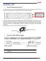
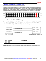
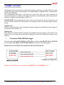
1
TECHNICAL DOCUMENTATION 26/09/2005
ECU
Notes: ECUs communication protocols and loggers connection
Version 1.10
Supported ECUs
“ECU communication protocol”: general information
The “available channels list” you find inside Race Studio 2 “Configuration” window is inferred
from the ECU’s communication protocol.
The communication protocol includes all the available channels of a generic Pectel/DTA etc.
ECU. The channels you may sample among the “available channels list” are function of the
ECU model, of the ECU configuration and of the wiring.
The number of channels that your data logger is able to sample depends on the ECU
type and configuration, on the wiring and on the sensors connected to the ECU itself.
To know which channels are acquired by your AIM logger, please check your Logger
channel page in Race Studio 2 software, where all recorded channels are shown.
Please note: for specific information on ECUs pinout and wirings always refer to Your
ECU user manual. Here follow some examples of ECU configuration and connection
with AIM loggers; these information come from tests made by AIM research and
development board or from our dealers or customers that have verified them.
Technical Documentation - Communication and connection manual: ECU-AIM loggers – Version 1.10
1
“Supported ECUs”: general information
AIM loggers support both CAN and RS232 communication protocol ECUs.
To know if your ECU model and communication protocol is supported, please refer to the
table below:
CAN protocol
●
●
●
●
●
●
●
●
●
●
●
●
●
●
●
●
●
●
●
●
●
●
●
●
●
●
●
●
●
●
BMW_Mini – Mod. BMW_Mini
Bosch – Mod. MS3
Bosch – Mod. MS4
Bosch – Mod. BoschVWGroup
Bosch – Mod. Porsche 911 (Mod. 996)
Brightwater – Mod. TyrePress4Sensor
Delphi – Mod. Mefi 4B
Denso – Mod. RX8
EFI EUROPE – Mod. EURO1
EFI EUROPE– Mod. EURO 6
EFI EUROPE – Mod. EURO 12
EFI EUROPE – Mod. EURO 96
Marelli – (Mod.) Customer Protocol
Marelli – Mod. FR2000
Marelli – Mod. FR1600
Marelli – Mod. RSA
Marelli – Mod. Toyota
Marelli – Mod. ToyotaB
MecTronic – Mod. MK_E4
MoTec – Mod. M400
MoTec – Mod. M400 – 1M
MoTec – Mod. M600
MoTec – Mod. M600 – 1M
MoTec – Mod. M800
MoTec – Mod. M800 – 1M
Racetech – Mod. EM_46
SEAT – Mod. ECU_1
Sodemo – Mod. EV_11
TMS – Mod. TyrePress
TMS – Mod. TyrePress4Sensor
RS232 serial protocol
●
●
●
●
●
●
●
●
●
●
●
●
●
●
●
●
●
●
●
●
●
●
Autronic – Mod. SM2_V190/1
Autronic – Mod. SMC_V191
Autronic – Mod. SM2_V193/195
Autronic – Mod. SM4
Carmo – Mod. AFI_2003
Carmo – Mod. AFI_2005
DTA – Mod. P8
DTA – Mod. P8V29
DTA – Mod. P8V30
EFI USA – Mod. 2.1
EMS – Mod. Stinger
GEMS – Mod. OMEX
MBE – Mod. 967
MBE - Mod. 970
MoTec – Mod. M4 (DataSet5 and DataSet3)
MoTec – Mod. M 48(DataSet5 and DataSet3)
MoTec – Mod. M8 (DataSet1)
Pectel – Mod. T2
Pectel – Mod. T6
Racetech – Mod. ENGMAN_18
Sybele – Mod. RS232
Wolf – Mod WOLF3D
Technical Documentation - Communication and connection manual: ECU-AIM loggers – Version 1.10
2
ECU connection: general information
Aim instruments can communicate with the ECU both with a CAN protocol and with an
RS232 protocol, using respectively a CAN cable or a Serial cable.
The connection is usually done as below explained:
•
Serial Communication Set-Up
The usual connection is as follows: please connect cable called RS232 RX with ECU TX and
cable called GND with ECU GND as in the figure below.
LOG GND
LOG RX
Cable labelled GND
ECU GND
ECU TX
Cable labelled RS232 RX
ECU
AIM LOGGER
Please note: this setup is all right for almost all ECU communicating with RS232 protocol;
there can anyway be ECUs that need LOG TX cable to be connected to ECU RX too. For
further information, please see paragraphs in the following pages, related to the single ECUs.
•
CAN Communication Set-Up
The connection is as follow: please connect cable labelled CAN+ with ECU CAN+, cable
labelled CAN- with ECU CAN- and cable called GND with ECU GND as in the figure below.
LOG GND
LOG CAN+
LOG CANAIM LOGGER
Cable labelled GND
Cable labelled CAN +
Cable labelled CAN -
ECU GND
ECU CAN+
ECU CANECU
Please note: once your ECU is connected to the AIM Logger, you need to set it in the logger
configuration in Race Studio 2 software.
Technical Documentation - Communication and connection manual: ECU-AIM loggers – Version 1.10
3
“AUTRONIC – SM2_V190/191 / SM2_V193/195 / SMC_V191”
•
Serial Communication Set-Up
The ECU is has a serial communication protocol (RS 232) and is equipped with a 36 pins
connector whose pinout is reported below used to communicate parameters to an external
data logger, or to configure the ECU itself.
•
Connection With AIM Data logger
To connect Your AIM logger to the ECU, please connect AIM cable labelled as “RS232RX”
with pin 33 of the ECU (ECU TX), AIM cable labelled as “GND” with pin 21 of the ECU
(ECU GND) as in the draw below.
LOG GND
LOG RX
AIM LOGGER
Pin
Function
21
33
GND
RS232TX
ECU GND
ECU TX
Cable labelled GND
Cable labelled RS232 RX
AUTRONIC SM2 V190/1911 ECU
Comments
Technical Documentation - Communication and connection manual: ECU-AIM loggers – Version 1.10
4
Here below is shown the 36 pins connector and its pinout.
12
1
24
13
36
25
Pin FUNCTION
1
2
3
4
5
6
7
8
9
10
11
12
13
14
15
16
17
18
19
20
21
22
23
24
25
26
27
28
29
30
31
32
33
34
35
36
Ignition O/P 7
Injector O/P 6
Injector O/P 4
Injector O/P 2
Injector O/P 1
Coolant Temp I/P
O2 I/P
Ref Trigger I/P
Serial I/O Rxd
Ignition O/P 4
Ignition O/P 2
Auxiliary O/P
ECU +12V supply
Injector O/P 8
Injector O/P 5
Injector O/P 3
Sensor GND
Throttle Position I/P
Throttle Position Supply
Trigger Supply
Serial I/O GND
Ignition O/P 3
Diagnostic O/P
Fuel Pump O/P
+12V Pump Rly Supply
+12V Aux O/P Supply
ECU GND
ECU GND
Ignition SW I/P
Air Intake Input I/P
Trigger GDN
Cyl Pulse Trigger I/P
Serial O/P Txd
GND
Ignition O/P 1
Ignition O/P
Technical Documentation - Communication and connection manual: ECU-AIM loggers – Version 1.10
5
“AUTRONIC – SM4”
•
Serial Communication Set-Up
The ECU has a serial communication protocol (RS 232) and is equipped with a 42 pins
connector and two jack input on its right, as shown in the figure below.
Jack Input for “PC
Serial
data
link
connector 3 way 3.5
dia” spiral cable
In the ECU package you find also a spiral cable, called “Pc Serial data link connector 3 way
3.5 dia” with a jack connector on one side, to insert in the right bottom jack input (drawn in
red colour in the previous figure) and a DB9 female connector on the other side. To correctly
connect your ECU to your AIM logger you have to connect your logger to the DB9 female
connector.
Here below you see the “PC Serial data link” spiral cable.
DB9 Female connector
Jack connector
•
Connection With AIM Data logger
To connect Your AIM logger to the ECU, please connect AIM cable labelled as “RS232RX”
with pin 2 of the DB9 female connector (that goes to ECU TX), AIM cable labelled “GND”
with pin 5 of the DB9 female connector (that goes to ECU GND) as in the draw below.
LOG GND
LOG RX
DB9 - Pin 5
DB9 - Pin 2
Cable labelled GND
Cable labelled RS232 RX
AIM LOGGER
Pin
Function
5
2
GND
RS232TX
TO ECU GND
TO ECU TX
DB9 Female Connector
Comments
Technical Documentation - Communication and connection manual: ECU-AIM loggers – Version 1.10
6
“BOSCH – MS3”
This ECU can be installed on Porsche 911 GT3 Cup cars.
On Porsche 911 GT3 Cup cars that have this ECU you find a 22 pins Deutsch connector with
red threading (Part Number RP 3759339), shown below.
12
16
20
22
17
5
6
•
13
15 21
15
3
4
14
1
2
18
7
11
19 10
8
9
Connection With AIM Data logger
To connect Your AIM logger to the ECU, please connect cable labelled CAN + with pin 4 of
the ECU, cable labelled CAN – with pin 16 of the ECU and cable labelled GND with pin 3 of
the ECU as shown in the figure below:
LOG GND
LOG CAN+
LOG CAN-
Cable labelled GND
Cable labelled CAN +
Cable labelled CAN -
BOSCH MS3 ECU
AIM LOGGER
Pin
4
16
3
Function
ECU GND
ECU CAN+
ECU CAN-
Comments
CAN +
CAN GND
Please note: if you want to power your AIM logger directly from the ECU, you can use pin
15 of the ECU (+12V), highlighted with a red coloured circle in the figure below.
Technical Documentation - Communication and connection manual: ECU-AIM loggers – Version 1.10
7
“BOSCH - PORSCHE 911 (Mod. 996)”
The ECU we call Bosch Porsche 911 is an ECU made by Bosch manufacturer and generally
installed on Porsche 911 cars (996 model). This ECU has a CAN Protocol and is equipped
with a 32 Pins green connector called “A” and used to communicate with an external data
logger as well as to configure the ECU itself. Bosch Porsche 911 connector is shown below.
A1
A16
A17
A32
•
Connection With AIM Data logger
To connect Your AIM logger to the ECU, please connect cable labelled CAN + with pin A15
of the ECU (CAN HIGH), cable labelled CAN – with pin 31 of the ECU (CAN LOW) and
cable labelled GND with pin GND of the ECU, as shown in the figure below:
LOG GND
LOG CAN+
LOG CAN-
Cable labelled GND
Cable labelled CAN +
Cable labelled CAN -
ECU PORSCHE BOSCH 911
AIM LOGGER
Pin
Function
A15
A31
CAN +
CAN -
ECU GND
ECU CAN+
ECU CAN-
Comments
Please note: as far as GND is concerned, please use the same GND you use for the ECU
Technical Documentation - Communication and connection manual: ECU-AIM loggers – Version 1.10
8
“CARMO - AFI 2003”
AIM loggers can be connected to both Carmo ignition or injection unit (AFI 2003); they can
acquire data from Carmo units installed on Honda CBR600, Kawasaki ZX6R, Yamaha YZ6F
and Suzuki GSXR600.
The configuration procedure is the same for every bike; when you have selected the
channels to acquire or to display, the logger will be able to automatically select the right set of
sensors, using the information given by AFI unit.
PLEASE NOTE: every manufacturer has it’s own set of sensors; if the set of sensors is not
the one usually used by the manufacturer for that type of bike, the acquired data could be
wrong.
Injection unit
All ECU channels listed in the configuration dialog window are available when the logger is
connected to the injection unit.
Ignition unit
Only RPM and Throttle Position channels are available when the logger is connected to the
ignition unit. In this case we recommend to disable the other ECU channels in order to save
memory.
•
Connection With AIM Data logger
Connect cable labelled RS 232 RX with ECU TX pin, cable called RS 232 TX with ECU RX
pin and cable called GND with ECU Power GND pin as shown in the figure below.
Please refer to Your ECU user manual to know Your ECU pinout.
LOG GND
LOG RX
LOG TX
Cable labelled GND
Cable labelled RS232 RX
Cable labelled RS232 TX
ECU GND
ECU TX
ECU RX
CARMO AFI 2003 ECU
Please note: this ECU needs connection of LOG TX cable to ECU RX pin too.
Technical Documentation - Communication and connection manual: ECU-AIM loggers – Version 1.10
9
“CARMO - AFI 2005”
AIM loggers can be connected to both Carmo ignition or injection unit (AFI 2005); they can
acquire data from Carmo units installed on Honda CBR600, Kawasaki ZX6R, Yamaha YZ6F
and Suzuki GSXR600.
The configuration procedure is the same for every bike; when you have selected the
channels to acquire or to display, the logger will be able to automatically select the right set of
sensors, using the information given by the AFI unit.
PLEASE NOTE: every manufacturer has it’s own set of sensors; if the set of sensors is not
the one usually used by the manufacturer for that type of motorbike, the acquired data could
be wrong.
Injection unit
All the ECU channels listed in the configuration dialog window are available when the logger
is connected to the injection unit.
Ignition unit
Only RPM and Throttle Position channels are available when the logger is connected to the
ignition unit. In this case we recommend to disable the other ECU channels in order to save
memory.
•
Connection With AIM Data logger
Your Carmo AFI 2005 ECU has two coloured connectors mounted on the backside, a grey
one and a black one. To connect your ECU with AIM loggers you need to connect cable
called RS 232 RX with ECU TX (pin A4 of the ECU grey connector), cable called RS 232
TX with ECU RX (pin A5 of the ECU grey connector) and cable called GND with the ECU
GND (pin A6 of the ECU grey connector) as shown in the figure below.
LOG GND
LOG RX
LOG TX
Cable labelled GND
Cable labelled RS232 RX
Cable labelled RS232 TX
ECU GND
ECU TX
ECU RX
CARMO AFI 2005 ECU
Please note: this ECU needs connection of LOG TX cable to ECU RX pin too.
Pin
Function
A6
A5
A4
GND
RS232RX
RS232TX
Comments
Technical Documentation - Communication and connection manual: ECU-AIM loggers – Version 1.10
10
Here below are shown AFI 2005 connectors and their pinout.
AFI 2005 Black Connector
AFI 2005 Grey connector
Pin
A8
A7
A6
A5
A4
A3
A2
A1
B8
B7
B6
B5
B4
B3
B2
B1
C8
C7
C6
C5
C4
C3
C2
FUNCTION
Ignitioncoil #3
Ignitioncoil #2
Ignitioncoil #1
Injector #1
Shower injector #1
Injector #2
Shower injector #2
Injector #3
Ignitioncoil #4
EXUP (-) not connected
EXUP (+) not connected
Ground EXUP-position-not connected
Signal EXUP-position–not connected
VCC EXUP-position-not connected
Injector #4
Power Ground
Power Ground
Shift-light output
Fan output
Shower injector #4
Pin
A8
A7
A6
A5
A4
A3
A2
A1
B8
B7
B6
B5
B4
B3
B2
B1
C8
C7
C6
C5
C4
C3
C2
C1
Shower injector #3
C1
AIM Logger Function
Ground
Down sensor
LOG GND
ECU Ground
LOG TX
ECU RX
LOG RX
ECU TX
ECT sensor
IAT sensor
MAP sensor
Ground
Launch control output
Quick-shift input
Ground TX RX (2)
TX (2)
2nd map input
TPS sensor
+12V
Ground
+5V sensors
Tacho output
Ground
RX (2)
Cam signal
Crank signal
Fuelpump relais
output
Technical Documentation - Communication and connection manual: ECU-AIM loggers – Version 1.10
11
“DTA - P8”
•
Serial Communication Set-Up
The ECU is equipped with a serial communication interface (RS 232) used to communicate
parameters to an external data logger, or to configure the ECU itself.
•
Connection With AIM Data logger
To connect Your AIM logger to the ECU, please connect AIM cable labelled as “RS232RX”
with ECU TX, AIM cable labelled as “GND” with ECU GND as in the draw below.
Please refer to Your ECU user manual to know Your ECU pinout.
LOG GND
LOG RX
AIM LOGGER
Cable labelled GND
ECU GND
ECU TX
Cable labelled RS232 RX
DTA P8 ECU
Technical Documentation - Communication and connection manual: ECU-AIM loggers – Version 1.10
12
“DTA - P8V30”
•
Serial Communication Set-Up
The ECU is equipped with a serial communication interface (RS 232) used to communicate
parameters to an external data logger, or to configure the ECU itself.
•
DTA Configuration
In order to make DTA ECU communicate with AIM Logger you need to configure the ECU
using DTAWin software. To do so, please follow these steps.
Launch DTAWin software. “Start Choice”
window is prompted. Please click on
“Connect” button.
If a windows saying “No Matching File on
disc Use Save to Make one” appears,
please click on “OK” button and then on
“Connect” button
DTAWin main window appears. Please
click on “File” button on the top toolbar
and select “Map Locking and Pin
Number” option.
When “Pin Number and Map Locking”
window appears, please enable “Unlock”
checkbox and press “OK” button.
Technical Documentation - Communication and connection manual: ECU-AIM loggers – Version 1.10
13
You step back to DTAWin Main window;
please click on “Other Map Settings” on
the top toolbar and select “Data Stream”
option.
When Serial Data Output for Dash
window appears, please set it as follows:
•
•
•
•
enable “Data Stream on?” checkbox
Fill “Number of Header Bytes 1-10”
box with number “2”
Set 208 on the first two rows of
Header Bytes Value box
Close the window clicking on the red
cross on the top right corner
A window asking you if you want to
update Serial Stream Settings appears;
please click on “Yes” button.
DTAWin main window appears. Please
click on “File” button on the top toolbar
and select “Map Locking and Pin
Number” option.
Technical Documentation - Communication and connection manual: ECU-AIM loggers – Version 1.10
14
When “Pin Number and Map Locking”
window appears, please enable “Lock”
checkbox and then press “OK” button.
DTAWin main window appears. Please
click on “File” button on the top toolbar
and select “Save (Download to disc)”
option.
“Save as” window appears. Please insert
file name and press “Save” button.
“Save Map file” window appears. Please
insert Map comment and click on “Save”
button.
Please note: this configuration has been tested on DTA P8V30 ECU, but we have good
reasons to think that this configuration should fit DTAP8 and DTA P8V29 ECU too.
Technical Documentation - Communication and connection manual: ECU-AIM loggers – Version 1.10
15
•
Connection With AIM Data logger
DTA P8V30 ECU has a DB15 female connector; to connect the ECU with AIM loggers you
need to have an RS232 DB15 male high resistance connector, shown below.
5
1
10
15
6
11
To connect Your AIM logger to the ECU, please connect AIM cable labelled as “RS232RX”
with Pin 3 of the RS232 DB15 male connector (goes to ECU TX), AIM cable labelled as
“GND” with Pin 5 of the RS232 DB15 male connector (goes to ECU GND) as in the draw
below.
LOG GND
LOG RX
ECU GND
ECU TX
Cable labelled GND
Cable labelled RS232 RX
AIM LOGGER
Pin DB15
5
3
Function
High resistance
RS232
19
DB15 Male connector
Comments
GND
RS232TX
Technical Documentation - Communication and connection manual: ECU-AIM loggers – Version 1.10
16
“EFI EUROPE ECU GENERAL INFORMATION”
•
Introduction
EFI ECUs actually supported by all those AIM instruments that can be interfaced with an
ECU are:
-
•
EURO 1
EURO 6
EURO 12
EURO 96
Technical communication notes
All EFI ECUs have a CAN line to export data to a third party data logger; this CAN line
normally works with two only wires
1. CAN hi ( corresponding to AIM Can + white wire)
2. CAN low ( corresponding to AIM Can - blue wire)
It is normally unnecessary to ground CAN line with our system.
To have communication between EFI and AIM devices you have to configure his ECU with
ECT software; please choose 2D data stream (this is valid for all models) in the proper page.
You can normally choose one of the following options:
1. UDA91 (for Magneti Marelli Dashboard)
2. 2D (for 2D and AIM loggers and dashes)
If getting data from the ECU is not possible first of all, please make an hardware check:
1. check if “line-end resistor” is installed: a 120 Ohm resistor should be found between
CAN+ and CAN– (this can be done with any multimeter); to do so, please disconnect
AIM instrument from the ECU and make this check on both side (ECU and logger);
2. check if amplitude of each “bit” is 2V (or at least 1.8 V); this test can be done with a
scope grounding the sond on CAN- wire and measuring on CAN+ ; please ensure
that no filtering feature is enabled on the scope (this because of high baud rate of this
line)
On a second step, please ensure that your dashboard is firm upped with the latest firm up
version and configured with the latest Race Studio 2 release.
Technical Documentation - Communication and connection manual: ECU-AIM loggers – Version 1.10
17
Once those conditions are satisfied, if the system continues not getting data from EFI
hardware, the problem is in EFI firmware. Please refer to the following table and contact an
EFI dealer to have the ECU upgraded.
EFI MODEL
CONNECTIBILITY AIM
EFI
LOGGERS-EFI
FIRMWARE
FIRMWARE
VERSION
WHAT TO DO
EURO 1
300
From 380
Nothing to select
EURO 1
400
Always
2d stream selection via software
EURO 96
300
From 310
2d stream selection via software
EURO 96
400
Always
2d stream selection via software
EURO 6 & 12
300
Always
2d stream selection via software
EURO 6 & 12
400
Always
2d stream selection via software
All models
200
Never
ECU Firm up needed; please
contact EFI for maps compatibility
with the new firmware
Technical Documentation - Communication and connection manual: ECU-AIM loggers – Version 1.10
18
“EFI EUROPE – EURO 1”
•
EFI ECU to AIM CAN Configuration
Please note: EFI Euro 1 ECU communication with AIM loggers depends on ECU firmware
version.
Euro 1 – until firmware version 379 included.
It is not possible to communicate; please contact EFI manufacturer to upgrade Your ECU
firmware.
Euro 1 – from firmware version 380 until firmware version 400:
In EFI configuration software protocol implemented in your ECU is perfectly compatible with
AIM loggers and works.
Euro 1 – from firmware version 400:
In ECU software, “ECT”, you can choose different datasets for CAN protocol management
concerning output data:
-
UDA 91
None
2D
Please select 2D protocol
•
Connection With AIM Data logger
Your ECU is equipped with a 35 pins AMP connector used to communicate parameters to an
external data logger or to configure the ECU itself.
To connect your AIM logger to the ECU, please connect cable labelled CAN + with pin 22 of
the ECU (CAN +), cable labelled CAN - with pin 6 of the ECU (CAN -) and cable labelled
GND with pin 23 of the ECU as in the figure below:
LOG GND
LOG CAN+
LOG CAN-
ECU GND
ECU CAN+
ECU CAN-
Cable labelled GND
Cable labelled CAN +
Cable labelled CAN -
AIM LOGGER
Pin
23
22
6
Function
EFI – EURO 1 ECU
Comments
GND
CAN +
CAN -
Technical Documentation - Communication and connection manual: ECU-AIM loggers – Version 1.10
19
“EFI EUROPE – EURO 6”
•
EFI ECU to AIM CAN Configuration
In ECU software, “ECT”, you can choose different datasets for CAN protocol management
concerning output data:
-
UDA 91
None
2D
Please select 2D protocol
•
Connection With AIM Data logger
The ECU is equipped with a 79 pins connector used to communicate parameters to an
external data logger or to configure the ECU itself.
To connect Your AIM logger to the ECU, please connect cables labelled CAN + with pin 55
of the ECU (CAN +), cable labelled CAN – with pin 70 of the ECU (CAN -) and cable called
GND with the pin 77 of the ECU (GND) as shown in the figure below:
LOG GND
LOG CAN+
LOG CAN-
ECU GND
ECU CAN+
ECU CAN-
Cable labelled GND
Cable labelled CAN +
Cable labelled CAN -
EFI – EURO 6 ECU
AIM LOGGER
Pin
Function
77
55
70
GND / DIG
CAN +
CAN -
Comments
Technical Documentation - Communication and connection manual: ECU-AIM loggers – Version 1.10
20
“EFI EUROPE – EURO 12”
•
EFI ECU to AIM CAN Configuration
In the ECU software, “ECT”, you can choose different dataset for CAN protocol management
concerning output data:
-
UDA 91
None
2D
Please select 2D protocol
•
Connection With AIM Data logger
The ECU is equipped with a 79 pins connector used to communicate parameters to an
external data logger or to configure the ECU itself.
To connect Your AIM logger to the ECU, please connect cables labelled CAN + with pin 10
of the ECU (CAN +), cable labelled CAN – with pin 9 of the ECU (CAN -) and cable called
GND with pin 72 of the ECU (GND) as shown in the figure below:
LOG GND
LOG CAN+
LOG CAN-
ECU GND
ECU CAN+
ECU CAN-
Cable labelled GND
Cable labelled CAN +
Cable labelled CAN -
EFI – EURO 12 ECU
AIM LOGGER
Pin
72
10
9
Function
Comments
GND
CAN +
CAN -
Technical Documentation - Communication and connection manual: ECU-AIM loggers – Version 1.10
21
“EFI EUROPE – EURO 96”
•
EFI ECU to AIM CAN Configuration
In ECU software, “ECT”, you can choose different datasets for CAN protocol management
concerning output data:
-
UDA 91
None
2D
Please select 2D protocol
•
Connection With AIM Data logger
The ECU is equipped with a 79 pins connector used to communicate parameters to an
external data logger or to configure the ECU itself. This connection should not change with
different firmware versions.
To connect Your AIM logger to the ECU, please connect cables labelled CAN + with pin 55
of the ECU (CAN +), cable labelled CAN – with pin 70 of the ECU (CAN -) and cable called
GND with the pin 77 of the ECU (GND) as shown in the figure below:
LOG GND
LOG CAN+
LOG CAN-
ECU GND
ECU CAN+
ECU CAN-
Cable labelled GND
Cable labelled CAN +
Cable labelled CAN -
EFI – EURO 96 ECU
AIM LOGGER
Pin
77
55
70
Function
Comments
GND
CAN +
CAN -
Technical Documentation - Communication and connection manual: ECU-AIM loggers – Version 1.10
22
“EFI USA – 2.1”
•
ECU communication protocol: general information
The “available channels list” you find inside Race Studio 2 “Configuration” window is inferred
from the ECU’s communication protocol.
The communication protocol includes all the available channels of an EFI USA 2.1. ECU. The
ECU is equipped with a 55 pins Deutsch connector used to communicate with an external
data logger or to configure the ECU itself.
•
AIM External Interface Board connection
To connect this ECU to AIM Loggers you need an external interface board supplied by AIM
(Part Number X05EFIUS210). This board needs to be connected to both the 55 pins Deutsch
connector of the ECU and to AIM Logger as shown below.
LOG 9-15 VDC Red wire AIM External Interface Board
LOG GND Black wire Part Number X05EFIUS210 White wire
LOG RX Blue wire
AIM LOGGER
ECU TX
EFI USA 2.1 ECU
The External interface board has all wires already labelled as follows:
-
Red wire:
Black wire:
Blue wire:
White wire:
9-15 VDC to connect to 9-15 VDC pin of AIM Logger
GND to connect to GND pin of AIM Logger
Data out to connect to RS232RX pin of AIM Logger
Data in to connect to pin “L” of the ECU 55 pins Deutsch connector.
Warning: please ensure that ECU GND, AIM External Interface Board GND and AIM
Logger GND are the same (in the pinout table below reported GND has been connected
to pin “AA”).
Technical Documentation - Communication and connection manual: ECU-AIM loggers – Version 1.10
23
•
EFI USA 2.1 – 55 Pins Deutsch connector pinout
The ECU is equipped with a 55 pins Deutsch connector, shown below and its pinout is
described in the following table.
Pin
A
B
C
D
E
F
G
H
J
K
L
M
N
P
R
S
T
U
V
W
X
Y
Z
a
b
c
d
e
Description
Pin
Description
INJ1
INJ2
INJ3
INJ4
Pump
Duty1
Duty2
Heater
Vref
Vref
TXD
ECU 12v
FCM/DC2
Lamp/Dc1
INJ6
INJ7
INJ8
INJ5
SW 1
SW2
MAP
Fuel P
Wheel
Wheel2
TPS
NGK/Knock
Crank
EBP
f
g
h
i
j
k
m
n
p
q
r
s
t
u
v
w
x
y
z
AA
BB
CC
DD
EE
FF
GG
HH
Cam
Oil P
Boost sw
Beacon
Lambda
Mixture
Fuel T
Air T
Water T
Oil T
Tach
IGN1
IGN2
IGN3
IGN4
IGN5/Step1+
IGN6/Step1IGN7/Step2+
IGN8/Step2GND
GND
GND
GND
GND
GND
GND
GND
Technical Documentation - Communication and connection manual: ECU-AIM loggers – Version 1.10
24
“GEMS – OMEX”
•
Serial Communication Set-Up
The ECU is equipped with a serial communication interface (RS 232) used to communicate
parameters to an external data logger or to configure the ECU itself. The ECU connector is
made of four sections: “A”, “B”, “C”, and “D” so characterised:
“A” - 26 pins
“B” - 16 pins
“C” - 12 pins
“D” – 22 pins
GEMX OMEX connector is shown below:
A1
A 13 B 1
B8 C1
A 14
A 26 B 9
B 16 C 7
•
C6
D1
D 11
C 12 D 12
D 22
Connection With AIM Data logger
Connect the cable called RS 232 RX with pin “C1” of the ECU (ECU TX) and cable called
GND with pin “A 13” or with the pin “A 26” of the ECU (GND pins) as shown in the figure
below:
LOG GND
LOG RX
AIM LOGGER
Cable labelled GND
ECU GND
ECU TX
Cable labelled RS232 RX
GEMS OMEX ECU
Technical Documentation - Communication and connection manual: ECU-AIM loggers – Version 1.10
25
“MARELLI – Customer Protocol (12 channels configuration)”
•
ECU Marelli configuration
Marelli ECUs can be configured so to communicate with AIM logger through Vision Software
(the software properly developed by Marelli for their ECU). This communication protocol is
called “Customer Protocol” because is a configuration you can set, with few differences, on
more ECUs. At present available configurations are for Marelli MF4 and Marelli RSA. Others
are following.
Customer protocol: Marelli MF4
First of all, please run Vision Software.
The window on the right appears
Please click on “Map” button on the top
toolbar and select Map Files (PTA)…
“ReadWrite Map (PTA) File” window
appears. Please press “Edit” button.
Technical Documentation - Communication and connection manual: ECU-AIM loggers – Version 1.10
26
“PTA table” window appears. Please scroll
the until “CAN COMMUNICATION” option
and double click on it.
The window on the right appears. Please
double click on “CAN Identifiers” option.
“Edit Table” window appears. Please insert
the following values:
●
column (1): 280
●
column (2): 284
●
column (3): 288
and close the window.
Technical Documentation - Communication and connection manual: ECU-AIM loggers – Version 1.10
27
The window on the right appears again.
Please double click on “CAN Table”
option.
“Edit Table” window appears again. Please
insert the following values:
●
row 0280: 0, 1, 2, 7
●
row 0284: 6, 5, 59, 11
●
row 0288: 9, 12, 49, 10
and close the window.
The window on the right appears; please
close it clicking on the cross on the top
right corner.
“Vision Windows Application” window
appears, asking if you want to save
changes. Please click on “Yes” button
Technical Documentation - Communication and connection manual: ECU-AIM loggers – Version 1.10
28
“Save as” window appears. Please insert
file name in the proper cell, choose file
destination folder and then click on “OK”
button.
“ReadWrite Map (PTA) File” window
appears. Please click on Exit button.
It is now necessary to transmit this
configuration to your ECU. “TX” button, on
the icons toolbar becomes enabled: please
press it.
Customer protocol: Marelli RSA
First of all, please run Marelli “Vision”
software. First software window appears.
Technical Documentation - Communication and connection manual: ECU-AIM loggers – Version 1.10
29
Please click on “File” button on the top
toolbar and select “Open” option, as in the
figure on the right.
“Open” window appears. Please browse
your CD and select “SRA_xxxxxx” folder
and then “CFG” folder
Please select the configuration you want to
set and click on “Open” button.
Vision “General” window appears.
Technical Documentation - Communication and connection manual: ECU-AIM loggers – Version 1.10
30
Please click on “Map” button on the top
toolbar and then select “Map files(PTA)..”
option as in the figure on the right.
“ReadWrite Map (PTA) File” window
appears. Please click on “Dir” button.
“Select PTA path” window appears. Please
select “PTA” folder and click on “Open”
button.
Technical Documentation - Communication and connection manual: ECU-AIM loggers – Version 1.10
31
Please select the desired file.
“ReadWrite Map (PTA) File” window
appears. Please click on “Edit” button.
“PTA Table” window appears. Please
scroll it and select “CAN LINK” option.
Technical Documentation - Communication and connection manual: ECU-AIM loggers – Version 1.10
32
Please double click on “CAN IDs” voice.
“Edit Table” window appears. Please insert
the following values:
●
column (1): 280
●
column (2): 284
●
column (3): 288
and close the window.
Please double click on “CAN packets
definition” voice.
“Edit Table” window appears again. Please
insert the following values:
●
row 0280: 0, 1, 2, 7
●
row 0284: 6, 5, 26, B
●
row 0288: D, C, 31, A
and close the window.
The window on the right appears. Please
close it clicking on the red cross on the top
right corner.
Technical Documentation - Communication and connection manual: ECU-AIM loggers – Version 1.10
33
“Vision Application window” appears,
asking you to save changes. Please click
on “Yes” button.
“Save As” window appears. Please insert
file name, select file destination folder and
then click on “Save” button.
“ReadWrite Map (PTA) File” appears
again. Please click on “Exit” button.
To transmit the configuration to your ECU,
please click on “TX” icon, that has become
enabled, on the top icons bar.
Technical Documentation - Communication and connection manual: ECU-AIM loggers – Version 1.10
34
When transmission is finished, please connect your Marelli ECU to your AIM logger
following the above reported CAN Communication Set-up
•
CAN Communication Set-Up
The connection is as follow: please connect cable labelled CAN+ with ECU CAN+, cable
labelled CAN- with ECU CAN- and cable called GND with ECU GND as in the figure below.
Please refer to your ECU’s user’s manual to know its pinout.
LOG GND
LOG CAN+
LOG CANAIM LOGGER
Cable labelled GND
Cable labelled CAN +
Cable labelled CAN -
ECU GND
ECU CAN+
ECU CANMARELLI ECU
Technical Documentation - Communication and connection manual: ECU-AIM loggers – Version 1.10
35
“MARELLI – RSA (complete 64 Channels configuration)”
•
ECU Marelli RSA configuration (64 Channels),
To configure your ECU Marelli RSA, please follow these steps.
• Launch Vision software.
• Click on File/ Open on the top toolbar
as in the figure on the right.
• The following windows appears.
Please look for CFG folder and open
it, as in the figure on the right.
• Select the desired CFG file and open
it.
• Click on “Map” button on the top
toolbar.
• And select “Map files” option.
Technical Documentation - Communication and connection manual: ECU-AIM loggers – Version 1.10
36
• Click on “Dir” button.
• Select the desired PTA file.
• Click on “Edit” button.
• Click on “Find” button, red circled in
the figure on the right.
• Digit “Data Elements” and click on
“OK” button.
Technical Documentation - Communication and connection manual: ECU-AIM loggers – Version 1.10
37
• If find next table name/reference
windows appears , please click on
“No” Button.
• Double click on “Data Elements Table”
option.
• Please insert in the first two columns
on the left of this table all digits
reported in the table you find at the
end of this explanation (the digits in
the other two columns are all right);
the table is called “Digits Table”
• When all digits have been inserted
(you reach row number 64), please
close the window.
• The window here on the right appears
again; please close it.
• The system asks you to save changes,
please click on “Yes” button.
Technical Documentation - Communication and connection manual: ECU-AIM loggers – Version 1.10
38
• The system asks you to choose file
destination folder; please select the
desired one and click on “Save”
button.
• ReadWrite Map (PTA) file windows
appears, please press “Exit” button.
• TX icon, on the top icons toolbar,
becomes enabled, please click on it to
transmit the configuration to the ECU
When transmission is finished, please connect your Marelli RSA ECU to your AIM logger
following the above reported CAN Communication Set-up
•
CAN Communication Set-Up
The connection is as follow: please connect cable labelled CAN+ with ECU CAN+, cable
labelled CAN- with ECU CAN- and cable called GND with ECU GND as in the figure below.
LOG GND
LOG CAN+
LOG CANAIM LOGGER
Cable labelled GND
Cable labelled CAN +
Cable labelled CAN -
ECU GND
ECU CAN+
ECU CANMARELLI RSA ECU
Technical Documentation - Communication and connection manual: ECU-AIM loggers – Version 1.10
39
Digits Table
(1)
(2)
(3)
(4)
(5)
(6)
(7)
(8)
(9)
(10)
(11)
(12)
(13)
(14)
(15)
(16)
(17)
(18)
(19)
(20)
(21)
(22)
(23)
(24)
(25)
(26)
(27)
(28)
(29)
(30)
(31)
(32)
(33)
(34)
(35)
(36)
(37)
(38)
(39)
(40)
(41)
(42)
(43)
(44)
(45)
(46)
(47)
(48)
(1)
00208270
00000000
00208080
00000000
0020808C
00000000
0002080A
00000000
0020808A
00000000
002080A8
00000000
00208088
00000000
00208086
00000000
00208084
00000000
002080A4
00000000
002080BC
00000000
00208392
00000000
00208082
00000000
0020808E
00000000
002080AA
00000000
00208094
00000000
002080B4
00000000
002080BA
00000000
00208E04
00000000
002080A6
00000000
00208D25
00208D26
00208D17
00208D18
00208846
00208845
0020883D
00208130
(2)
00000002
00000001
00000082
00000001
00000082
00000001
00000082
00000001
00000082
00000001
00000082
00000001
00000082
00000001
00000082
00000001
00000082
00000001
00000082
00000001
00000002
00000001
00000082
00000001
00000082
00000001
00000082
00000001
00000002
00000001
00000082
00000001
00000002
00000001
00000002
00000001
00000002
00000001
00000082
00000001
00000001
00000001
00000001
00000001
00000001
00000001
00000001
00000001
(3)
3F800000
3F800000
3F800000
3F800000
3F800000
3F800000
3F800000
3F800000
3F800000
3F800000
3F800000
3F800000
3F800000
3F800000
3F800000
3F800000
3F800000
3F800000
3F800000
3F800000
3F800000
3F800000
3F800000
3F800000
3F800000
3F800000
3F800000
3F800000
3F800000
3F800000
3F800000
3F800000
3F800000
3F800000
3F800000
3F800000
3F800000
3F800000
3F800000
3F800000
3F800000
3F800000
3F800000
3F800000
3F800000
3F800000
3F800000
3F800000
(4)
00000000
00000000
00000000
00000000
00000000
00000000
00000000
00000000
00000000
00000000
00000000
00000000
00000000
00000000
00000000
00000000
00000000
00000000
00000000
00000000
00000000
00000000
00000000
00000000
00000000
00000000
00000000
00000000
00000000
00000000
00000000
00000000
00000000
00000000
00000000
00000000
00000000
00000000
00000000
00000000
00000000
00000000
00000000
00000000
00000000
00000000
00000000
00000000
Technical Documentation - Communication and connection manual: ECU-AIM loggers – Version 1.10
40
(49)
(50)
(51)
(52)
(53)
(54)
(55)
(56)
(57)
(58)
(59)
(60)
(61)
(62)
(63)
(64)
00208385
00208383
00208381
002085B7
002085B8
002085B6
002085B5
00208386
002080B0
00000000
00208A18
00000000
00000000
00000000
00000000
00000000
00000001
00000001
00000001
00000001
00000001
00000001
00000001
00000001
0000820E
00000001
0000820E
00000001
00000001
00000001
00000001
00000001
3F800000
3F800000
3F800000
3F800000
3F800000
3F800000
3F800000
3F800000
3F800000
3F800000
3F800000
3F800000
3F800000
3F800000
3F800000
3F800000
00000000
00000000
00000000
00000000
00000000
00000000
00000000
00000000
00000000
00000000
00000000
00000000
00000000
00000000
00000000
00000000
Technical Documentation - Communication and connection manual: ECU-AIM loggers – Version 1.10
41
“MBE – 967”
•
Serial Communication Set-Up
The ECU has a serial communication protocol (RS232) and a 36 pins connector, whose
pinout is below, used to communicate with an external logger, or to configure the ECU itself.
18
1
19
Pin
1
2
3
4
5
6
7
8
9
10
11
12
13
14
15
16
17
18
19
20
21
22
23
24
25
26
27
28
29
30
31
32
33
34
35
36
36
Function
Comments
Fuel trim
Water temp. signal
Air temp. signal
5v analogue
Analogue GND
Power GND
POWER GND
Power GND
Power GND
Gear input
Crank return
Crank signal
ECU supply
Serial receive
Faul light / switch
Shift light
Fuel pump relay drive
Ignition drive 2
Power shift input
Throttle signal
Map signal
5v analogue
Analogue GND
Analogue GND
Oil temperature
Ignition trim
Oil pressure
Barom. press./launch input
Lambda signal
Not used
Not used
SERIAL TRANSMIT
Radiator fan relay drive
Tachometer signal
Injection output
Ignition drive 1
Mp 06
Mp 04
Mp 05
Mp 01
Mp 03: RS232 com. – ECU RX
Switched Ground
Switched Ground
Cylinders 2 + 3
Ground active
Mp 07
Not used
Not used
Mp 02: RS232 com. – ECU TX
Switched Ground
All Cylinders
Cylinders 1 + 4 (coil if distributor fitted)
Mp = Mapping plug
Technical Documentation - Communication and connection manual: ECU-AIM loggers – Version 1.10
42
To connect the ECU to a PC, using a standard DB9 female connector, pin 32 (ECU TX) of
the ECU must be connected to pin 2 of the DB9 and pin 7 (or other Power GND pins) of the
ECU must be connected to pin 5 of the DB9.
To communicate with the PC ECU’s Fuel Trim (pin 1) and Ignition Trim (pin 26) inputs must
be hold at a voltage other than zero; this procedure enables the “Byte Mode” and allows the
ECU to communicate with EasiMap Windows tool (the MBE configuration program – see
ECU manual for more information).
•
ECU Configuration
In order to communicate with the data logger, the ECU must be properly configured using the
program “EasiMap” provided with the same ECU.
PLEASE NOTE: EasiMap v5.0 software can be used to configure data logging feature only
by user with “Advanced” profile; see MBE site: http://www.mbesystems.com/index.html
1.
2.
3.
4.
5.
Connect the ECU to a PC with EasiMap 5.0 installed, and turn on power to the ECU
[ECU pin 13 at 12V and ECU pin 6 (or other Power GND) at GND].
Launch EasiMap 5.0 software; choose the [Get Data…] option from the [Data] menu.
In the window [Select Parameter] open the [Data Logging] directory and select [Data
Logger Link]; choose [ECU Device] in the [Data Source] options and then press [OK].
Now the program reads information from the ECU and opens a new window to
configure the communication.
The parameters must be configured in the right sequence and with the right
scaling in order to communicate with the AIM data logger:
Data Logger Link: choose [Transmitting at 19200]
RPM: choose [4,00]
Parameter
1: choose [Engine Speed]
2: choose [Ignition]
3: choose [Injection Time]
4: choose [Throttle Angle]
5: choose [Coolant Temp]
6: choose [Air Temp]
7: choose [Baro Pressure]
8: choose [Lambda]
9: choose [Ri]
10: choose [Engine Oil Pressure]
11: choose [Fuel Pressure]
12: choose [Water Pressure]
13: choose [Engine Oil Temp]
14: choose [Gearbox Oil Temp]
15: choose [Boost Pressure]
16: choose [Gear Position]
6.
7.
Scaling
Choose 16 bit
Choose 8 bit
Choose 16 bit
Choose 8 bit
Choose 8 bit
Choose 8 bit
Choose 8 bit
Choose 8 bit
Choose 16 bit
Choose 8 bit
Choose 8 bit
Choose 8 bit
Choose 8 bit
Choose 8 bit
Choose 8 bit
Choose 8 bit
When all parameter are configured, please press [Send] button and choose [ECU
Device] when requested; configuration is saved in the ECU memory.
Please close configuration window and quit the program. Before connecting ECU to
the Data logger, please enable “Broadcast Mode” ensuring a nominally zero voltage
(or open circuit) on Fuel Trim and Ignition Trim inputs.
Technical Documentation - Communication and connection manual: ECU-AIM loggers – Version 1.10
43
•
Connection With AIM Data logger
Connect cable labelled RS 232 RX with pin 32 of the ECU (ECU TX) and cable labelled GND
with pin 7 of the ECU (or other Power GND pins) as shown in the figure below:
LOG GND
LOG RX
ECU GND
ECU TX
Cable labelled GND
Cable labelled RS232 RX
AIM LOGGER
Pin
Function
7
32
GND
RS232TX
MBE 967 ECU
Comments
Technical Documentation - Communication and connection manual: ECU-AIM loggers – Version 1.10
44
“MBE – 970”
•
Serial Communication Set-Up
The ECU is equipped with a serial communication interface (RS 232) used to communicate
parameters to an external data logger, or to configure the ECU itself.
The pinout for MBE-967 ECU is shown below:
Pin
50
46
•
Function
Comments
POWER GND
RS 232 TX
Connection With AIM Data logger
Connect the cable labelled RS 232 RX with pin 46 of the ECU (ECU TX), and cable labelled
GND with pin 50 of the ECU (ECU GND) as shown in the figure below:
LOG GND
LOG RX
AIM LOGGER
Cable labelled GND
ECU GND
ECU TX
Cable labelled RS232 RX
MBE 970 ECU
Technical Documentation - Communication and connection manual: ECU-AIM loggers – Version 1.10
45
“MecTronik – MK_E4”
•
MecTronik connection to AIM data logger.
MecTronik company produces two MK_E4 ECU version: the standard one and the drive
by wire one.
Identification of the two version is possible through the ECU serial number.
•
Standard version serial numbers are:
- xx HA xxx
- xx HB xxx
- xx HC xxx
•
Drive by Wire version serial numbers are
- Xx HD xxx
Where “HA” “HB” “HC” “HD” are the codes that identify the ECU version.
Both MK_E4 ECUs are equipped with a 41 pins connector. To connect Your AIM logger to
the ECU, please connect cable labelled CAN + with ECU CAN + pin, cable called CAN with ECU CAN - and cable called GND with ECU GND as shown in the figure below:
LOG GND
LOG CAN+
LOG CAN-
ECU GND
ECU CAN+
ECU CAN-
Cable labelled GND
Cable labelled CAN +
Cable labelled CAN -
AIM LOGGER
MecTronik MK_E4 ECU
As far as ECUs pins are concerned, please refer to the following tables to know which pin
is to be connected to which cable.
MK_E4 – Standard version (codes: “xx HA xxx”, “xx HB xxx”, “xx HC xxx”)
Pin
Function
H
J
Y
ECU GND
CAN +
CAN -
Comments
MK_E4 – Drive by Wire version (codes: “xx HD xxx”)
Pin
Function
H
J
c
ECU GND
CAN +
CAN -
Comments
Technical Documentation - Communication and connection manual: ECU-AIM loggers – Version 1.10
46
“MoTec – M400 / M600 / M800”
•
MoTeC ECU to AIM CAN Configuration
In MoTeC ECU Manager configuration, go to Adjust/General Setup/ Miscellaneous Setup and
set the CAN data set to 1 and the CAN Address to 1520 as in the figure below.
Please note: If the MoTeC CAN communication cable is connected, PC will take CAN
priority. AIM logger will not receive data. After configuration, please ensure that MoTeC
communication cable is disconnected.
•
Connection With AIM Data logger
The ECU is equipped with a CAN communication interface used to communicate parameters
to an external data logger or to configure the ECU itself.
MoTec M800 ECU has two connectors, shown in the figure below. The two connectors are
labelled “A” connector and “B” connector.
A1
A1
A9
B7
B1
A10
A17
B8
B13
A18
A25
B14
B19
A26
A34
B20
Technical Documentation - Communication and connection manual: ECU-AIM loggers – Version 1.10
B26
47
To connect Your AIM logger to the ECU You need to use connector labelled as “B”. Please
connect cable labelled CAN + with pin 23 of the ECU (CAN +), cable labelled CAN - with pin
24 of the ECU (CAN -) and cable called GND with pin 14 of the ECU as in the figure below:
LOG GND
LOG CAN+
LOG CAN-
ECU GND
ECU CAN+
ECU CAN-
Cable labelled GND
Cable labelled CAN +
Cable labelled CAN -
MoTec M400 –
M600 – M800 ECU
AIM LOGGER
Pin
Function
B 14
B 23
B 24
POWER GND
CAN +
CAN -
•
Comments
AIM Data logger configuration
For ECU with MoTec firmware version 2.30S2 onward, once you have correctly connected
your AIM Logger to the ECU to correctly configure your logger with Race Studio 2 software,
please select the following configuration options.
●
ECU Manufacturer:
MoTec
●
ECU Model:
M800-M600-M400-1M
Technical Documentation - Communication and connection manual: ECU-AIM loggers – Version 1.10
48
“MoTec – M4”
Please note Motec M4 ECU is supported only from serial number 3000 onwards.
•
MoTeC ECU to AIM RS232 Configuration
Please run MoTeC configuration Software and press enter button. Then select Adjust
function and press enter button. Scroll the page and select General Setup in “Select” window.
Then choose Miscellaneous Setup 2.
Set Telemetry Baud Rate to 9601, (9600) and Telemetry Data Set to 5, (ADL Dash Logger).
9601
•
MoTeC ECU to AIM RS232 Connection
Please note: if MoTeC RS-232 communication cable is connected to the ECU and MoTeC
software is active, PC takes priority. AIM does not receive data. Close MoTeC software
or make sure that MoTeC software is not active.
The ECU is equipped with an RS232 communication protocol used to communicate
parameters to an external data logger, or to configure the ECU itself.
To connect AIM logger to the ECU you need to use a DB9 female connector. Please connect
Pin 2 of the DB9 female connector to AIM cable labelled as “RS232RX” and Pin 5 of the
DB9 female connector to AIM cable labelled as “GND” as in the draw below:
LOG GND
LOG RX
Cable labelled GND
DB9 - Pin 5
DB9 - Pin 2
Cable labelled RS232 RX
AIM LOGGER
Pin
Function
5
2
GND
RS232RX
TO ECU GND
TO ECU TX
DB9 Female Connector
Comments
Technical Documentation - Communication and connection manual: ECU-AIM loggers – Version 1.10
49
“MoTec – M48”
•
MoTeC ECU to AIM RS232 Configuration
Motec M-48 ECU can be interfaced to Aim loggers through two different communication
protocols based upon two different setups agreed by MoTec firmware.
Motec M 48 needs a MoTec PC connection cable to be interfaced to a Pc; please address to
MoTec to know its part number.
Before connecting Your ECU to AIM loggers, please check its setup; to do so, connect it to
the serial port of Your Pc using MoTec ECU Menu V6.20 software you can download free of
charge from MoTec website www.motec.com.au.
If when connecting your ECU to the Pc MoTec software recognizes an older version, an
upgrade is needed and this is possible through a Software Update Unit, available from most
MoTec dealers. Upgrading is automatically done by the software selecting the related voice
in MoTec software. If on the contrary, when connecting your ECU to the Pc MoTec software
recognizes a corresponding software version, upgrade is not needed.
Once the ECU upgraded (when necessary),please run MoTec software and follow this
procedure:.
Select EMP (Engine Management
Program).
Please select “Adjust”. This way
the software acquires ECU setup.
If asked, please select the voice
“use matching file”
Please select “General Setup” and
then Miscellaneous setup 2.
Technical Documentation - Communication and connection manual: ECU-AIM loggers – Version 1.10
50
In this setup you can use DataSet5 (the most recent and common) or DataSet3.
Here are values corresponding to the two setups.
DataSet5
Diag Error Hold Time
Telemetry Baud Rate
Telemetry DataSet
InternalLogSet
InternalLoggingRate
Advanced Tuning
0
9601
5
0
5
1
DataSet3
Diag Error Hold Time
Telemetry Baud Rate
Telemetry DataSet
InternalLogSet
InternalLoggingRate
Advanced Tuning
0
9601
3
3
5
1
Once entered these values You can save Setup on current file or on a new one. Changes are
automatically saved by the software and the ECU is restarted.
•
MoTeC ECU to AIM RS232 Connection
Please note: if MoTeC RS-232 communication cable is connected to the ECU and MoTeC
software is active, PC takes priority. AIM logger does not receive data. So, please close
MoTeC software or make sure that is not active.
The ECU is equipped with an RS232 communication protocol used to communicate
parameters to an external data logger, or to configure the ECU itself. MoTec M4 ECU has a
36 pin connector, shown in the figure below and needs a DB9 female connector for external
communication and of course to communicate to AIM logger too.
1
12
13
24
25
26
Please connect AIM cable labelled “RS232RX” to Pin 2 of the DB9 female connector and
Pin 5 of the DB9 female connector to AIM cable labelled as “GND” as in the draw below:
LOG GND
LOG RX
Cable labelled GND
DB9 - Pin 5
DB9 - Pin 2
Cable labelled RS232 RX
AIM LOGGER
Pin
Function
5
2
GND
RS232RX
TO ECU GND
TO ECU TX
DB9 Female Connector
Comments
Technical Documentation - Communication and connection manual: ECU-AIM loggers – Version 1.10
51
“PECTEL – T2”
•
Serial Communication Set-Up
The ECU is equipped with a serial communication interface (RS 232) used to communicate
parameters to an external data logger, or to configure the ECU itself.
The pinout for Pectel T2 ECU is shown below:
13
1
26
Pin
1
14
2
15
3
16
4
17
5
18
6
19
7
20
8
21
9
22
10
23
11
24
12
25
13
14
Function
Comments
IGN1
IGN2
INJ1 HIGH IMP
INJ2 HIGH IMP
INJ3 HIGH IMP
INJ4 HIGH IMP
PWM1
PWM2
ENG GROUND
ENG GROUND
12V+ve
RS 232 RX
RS 232 TX
PWM3
CRANK
CAM
MAF/MAP
TPS
LAMV
ECT
ACT
SPARE ANALOG
SENSOR GND
5V+ve
SPARE DIGITAL
Build option: low side / TTL coil driver
Build option: low side / TTL coil driver
High impedance only
High impedance only
High impedance only
High impedance only
Low side (10A maximum)
Low side (10A maximum)
RS 232 communication – ECU RX
RS 232 communication – ECU TX
Low side (10A maximum)
Crank sensor input
Cam sensor input
Analog input
Analog input
Lambda sensor
Analog input
Analog input
Analog input
Analog ground
200 mA maximum
Switched input
To connect the ECU to a PC, you need a standard DB9 female connector; please connect
pin 7 (ECU TX) of the ECU to pin 2 of the DB9 and pin 18 (GND) of the ECU to pin 5 of the
DB9.
Technical Documentation - Communication and connection manual: ECU-AIM loggers – Version 1.10
52
•
ECU Configuration
The ECU needs an appropriate configuration through the program “Descpro”, provided by
Pectel to communicate with AIM logger. To configure the ECU, please follow these steps:
1.
2.
3.
4.
5.
6.
7.
8.
•
Connect the ECU to a PC with Descpro installed, and turn on power to the ECU
(ECU pin 6 at 12V and ECU pin 5,18 at GND).
Launch Descpro software; at start-up mark [Serial], choose the right [COM] port and
click on [On-line] button.
The software reads the ECU configuration (called “MAPS”); when finished, press
[Menu] button top-right on the screen, and choose [Software Setup] in the next
window.
Now choose [Data Logging And Serial Comms] with arrow-keys and press return
(or double click with mouse pointer).
Select [Default Communication Mode] and press return.
The default mode should be [PC], press return and a dialogue-windows appears (Set
to:); you must choose [STACK] and press return.
The new configuration must be transmitted to the ECU before quitting the program:
click on [File] button (bottom-left) and choose [Program current maps into ECU
flash]; confirm the operation when prompted.
After the transfer is finished quit the program Decspro; ECU is ready to communicate
with AIM loggers.
Connection With AIM Data logger
Connect cable labelled RS 232 RX with pin 7 of the ECU (ECU TX), and cable labelled GND
with pin18 of the ECU (ECU GND) as shown in the figure below:
LOG GND
LOG RX
ECU GND
ECU TX
Cable labelled GND
Cable labelled RS232 RX
Pectel T2 ECU
AIM LOGGER
Pin
Function
18
7
GND
RS232TX
Comments
Technical Documentation - Communication and connection manual: ECU-AIM loggers – Version 1.10
53
“PECTEL – T6”
•
Serial Communication Set-Up
The ECU is equipped with a serial communication interface (RS 232) used to communicate
parameters to an external data logger, or to configure the ECU itself.
Pectel T2 ECU has a 55 pins AMP connector shown below:
19
1
37
20
38
55
Pin Function
1
20
38
2
21
39
3
22
40
4
23
41
5
24
42
6
25
43
7
26
44
8
27
45
9
28
46
10
29
47
11
30
48
12
SW2
SW1
LAMI2
LAMV2
PWM6/DET2
LAMI1
LAMV1
5V SENSOR SUPPLY
Sensor GND
SP2(AN8)
SP1(AN7)
MAP (AN6)
TPS(AN5)
SP4(AN4)
SP3(AN3)
ECT(AN2)
ACT(AN1)
ROT4
THERMOSIG
ROT3
ROT2
ROT1
DET1
PWM5
CAMSIG
CRANKSIG
COMMSGND
RS232TX
RS232RX
CAN LOW
CAN HIGH
ENGGND
ENGGND
ENGGND
Comments
Switch input. Internal 22k Pullup
Switch input. Internal 22k Pullup
Lambda Sensor 2
Lambda Sensor 2
Build Option. Knock Sensor 2 or Low side drive
Lambda Sensor 1
Lambda Sensor 1
200mA maximum
Analog input. Software Select Input Type
Analog input. Software Select Input Type
Analog input. Software Select Input Type
Analog input. Software Select Input Type
Analog input. Software Select Input Type
Analog input. Software Select Input Type
Analog input. Software Select Input Type
Analog input. Software Select Input Type
Digital input. Software Select 10k Pullup
K Type thermocouple input
Digital input. Software Select 10k Pullup
Digital input. Software Select 10k Pullup
Digital input. Software Select 10k Pullup
Knock Sensor 1
Low Side Drive
CAM sensor
Crank sensor
Comms ground
RS232 comms
RS232 comms
CAN communications
CAN communications
Technical Documentation - Communication and connection manual: ECU-AIM loggers – Version 1.10
54
31
49
13
32
50
14
33
51
15
34
52
16
35
53
17
36
24
18
37
55
19
•
1.
2.
•
12V ECU SUPPLY
PWM4
PWM3
PWM2
PWM1
INJ12/IGN8/PWM10
INJ11/IGN7/PWM9
INJ10/IGN6/PWM8
INJ9/IGN5/PWM7
INJ8
INJ7
INJ6
INJ5
INJ4
INJ3
INJ2
INJ1
IGN4
IGN3
IGN2
IGN1
Low Side Drive (10A maximum)
Low Side Drive (10A maximum)
Low Side Drive (10A maximum)
Low Side Drive (10A maximum)
Build Option–Injector drive/Ignition/Low Side Drive (10A max.)
Build Option–Injector drive/Ignition/Low Side Drive (10A max.)
Build Option–Injector drive/Ignition/Low Side Drive (10A max.)
Build Option–Injector drive/Ignition/Low Side Drive (10A max.)
Software Select Low/High impedance injector drive (10A max)
Software Select Low/High impedance injector drive
Software Select Low/High impedance injector drive
Software Select Low/High impedance injector drive
Software Select Low/High impedance injector drive
Software Select Low/High impedance injector drive
Software Select Low/High impedance injector drive
Software Select Low/High impedance injector drive
Build Option: Low Side/TTL Coil Drive
Build Option: Low Side/TTL Coil Drive
Build Option: Low Side/TTL Coil Drive
Build Option: Low Side/TTL Coil Drive
ECU Configuration
To connect the ECU to a PC, you need to use a standard DB9 female connector;
please connect pin 10 (ECU TX) of the ECU to pin 2 of the DB9 and pin 30 (GND) of
the ECU to pin 5 of the DB9
The ECU must be properly configured using the program “Descpro” provided by
Pectel to communicate with the data logger. Suggested configuration is the same of
Pectel T2 ECU. Please note: pins used to power Pectel T6 are: pin 31 12V and pins
30, 48 or 12 for GND.
Connection With AIM Data logger
Connect cable labelled RS 232 RX with pin 10 of the ECU (ECU TX), and cable called GND
with pin 30 of the ECU (ECU GND) as shown in the figure below:
LOG GND
LOG RX
AIM LOGGER
Cable labelled GND
ECU GND
ECU TX
Cable labelled RS232 RX
Pectel T6 ECU
Technical Documentation - Communication and connection manual: ECU-AIM loggers – Version 1.10
55
“SYBELE – RS232”
Sybele RS232 ECU is equipped with a 35 pins male connector (shown below) used to
communicate with an external data logger and to configure the ECU itself.
•
Connection With AIM Data logger
Connect cable labelled RS 232 RX with ECU TX (pin 13 of the 35 pins male connector),
cable called RS 232 TX with ECU RX (pin 31 of the 35 pins male connector) and cable called
GND with ECU Power GND (pin 29 of the 35 pins male connector) as shown in the figure
below.
LOG GND
LOG RX
LOG TX
Cable labelled GND
Cable labelled RS232 RX
Cable labelled RS232 TX
ECU GND
ECU TX
ECU RX
SYBELE RS232 ECU
AIM LOGGER
Please note: this ECU needs connection of LOG TX cable to ECU RX pin too.
Here below you can see Sybele RS232 35 pins male connector and its pinout.
19
35
1
18
PIN
Function
31
13
29
RS232RX
RS232TX
GND
Comments
Technical Documentation - Communication and connection manual: ECU-AIM loggers – Version 1.10
56