1
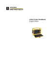
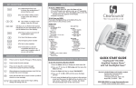
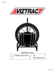
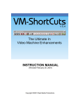
vCam Pro User Manual EDENBROS, LLC Toll Free: 1-800-526-5246 ● Fax: 1-800-526-5246 ● Cell: 630-346-8113 E-Mail: [email protected] ● Web: www.edenbros.com PO Box 3987 ● Naperville, IL 60567 USA Table of Contents 1 INTRODUCTION ....................................................................................................................2 1.1 SYSTEM FEATURES...................................................................................................2 1.2 SYSTEM COMPONENTS............................................................................................2 1.3 CONTROL BOX FRONT PANEL .................................................................................3 1.4 COMMAND MODULE COVER....................................................................................5 2 OPERATING INSTRUCTIONS...............................................................................................7 2.1 SETTING UP THE COMMAND MODULE...................................................................7 2.2 POWERING UP THE SYSTEM ...................................................................................7 2.3 FUNCTION OF THE EQUIPMENT ..............................................................................8 2.4 USING THE TRANSMITTER AND RECEIVER ...........................................................8 2.5 USING THE TELEVISION AND DVD PLAYER ...........................................................9 2.5.1 USING THE LCD................................................................................................9 2.5.2 USING THE DVD RECORD ..............................................................................9 3 TROUBLESHOOTING..........................................................................................................10 1 INTRODUCTION 1.1 SYSTEM FEATURES The vCam System has many features that assist the user to operate the system efficiently and obtain good results in a wide variety of applications. Operational capabilities and features include: Basic components of the system are a Command Module and Cable Reel with integral cable and camera. These are designed for ease of use and portability. Pipeinspections – The camera can be pushed through 180 and 90 degree bends, such as P traps. The camera (and attachments) is designed so that if they can be pushed forward through a pipe, they will return by the same route (assuming pipe integrity is maintained). Camera and cable deployment - Inspection cables up to 400 ft (120 m) in length are available. Cable deployment is measured by counting rotations of the cable drum and calculating the length depending on the cable reel size. The displayed length can be reset to zero when the camera passes a reference point, thus assisting distance estimates once in the pipe. The Camera has integral LEDs to illuminate the scene. Illumination is fully controllable. Camera Location - An integral transmitter at the camera end of the cable allows easy location and depth measurement from the surface, using a Locator. Monochrome or color monitoring is possible, with full recording and playback capabilities. Titles, plus date, time and distance measurement may be added to the display and recorded with the camera image for reference purposes. 1.2 SYSTEM COMPONENTS The main components of the vCam System are shown in Figure 1. These and other optional components are listed and described in the table below. Components Command Module Cable reel Camera assembly Interface cable Description LCD/DVD player/recorder options for both PAL and NTSC. Used to monitor the camera picture and record the image, with screen titles and commentary as necessary. Houses integral Monitor/DVD player/recorder, titler and microphone, and provides all camera/image controls. Also provides transmit signal for camera location. 60 m (200 ft) cable which is terminated with Color Camera Integral LEDs to illuminate the scene. Illumination is fully controllable. Connection between Command Module and Cable Reel 2 3 CABLE REEL 1 CAMERA ASSEMBLY 2 COMMAND MODULE 4 INTERFACE CABLE Power On Indicator Transmitter Mic. External Mic. On/Off Microphone Reset Video out Keyboard Graphics Dimmer Ca Reel Camera AV MODE TIMER M - + POWER On/Off Power STANDBY N/CLOSE PLAY/PAUSE STOP REC REC€ SOURCE MODE Figure 1 Main vCam System Components 1.3 CONTROL BOX FRONT PANEL The Command Module front panel contains the LCD/DVD player/recorder and all the controls and connectors necessary for the operation of the vCam System. The controls and connector panel is subdivided into five functional areas as shown in Figure 2 and described in the table below. Control panel area Transmitter Controls connectors Transmitter ON/OFF and Description POWER ON INDICATOR Microphone ON/OFF MIC EXTERNAL MIC Graphics RESET Camera VIDEO OUT KEYBOARD DIMMER CAMERA REEL Press to switch the transmitter, located at the end of the camera cable, ON/OFF. This is used for camera location, but should be switched off when not in use. Lit to indicate power to the Command Module is switched ON. Switches internal or external microphone ON/OFF Internal microphone Jack socket for external microphone Used to initiate the sequence that resets the cable length measurement and clear the text on the screen Jack socket for output video for reference purposes Connector for keyboard Adjusts brightness of camera LEDs Connector for interface cable from the Cable Reel. 3 Power ON/OFF FUSE Control Box Power ON/OFF switch Control Box fuse Figure 3 Command Module Front Panel 4 1.4 COMMAND MODULE COVER The Command Module cover provides a convenient storage location for items associated with the Command Module. Foam and securing straps are used to secure the items to prevent damage during transportation. Component Keyboard Remote control *Spanner wrench Description Use to title on the screen Use to control the DVD player/recorder Use to remove the camera assembly *optional 1.5 CABLE REEL COMPONENTS The construction of cable reel is shown in Figure 4. The Cable Reel features are described in the following table. Figure Reference Component Description A Cable Drum The cable drum has an open construction for ease of cleaning. The cable is permanently connected to a slip ring assembly at the hub. B Slip Ring The slip ring assembly houses a plug for Assembly connection of the interface cable. The slip rings provide the connections between this plug and the camera cable on the rotating drum. A device within the slip ring assembly indicates each rotation of the drum for use in calculating the displayed cable length. C Interconnection For storage of the Cable Reel to Control Unit Cable Hooks Interconnect Cable. D Brake Assembly Controls rotation of Cable Drum. E Wheels Easily removable wheels that assist transportation. F Feet Three additional feet are provided on the side of the Standard Reel only, to allow it to be laid on its side. 5 Figure 4 Cable Reel Components 6 2 OPERATING INSTRUCTIONS 2.1 SETTING UP THE COMMAND MODULE Figure 5 Command Module case The Command Module case is shown in Figure 5. The handle can be adjusted to a vertical position as the stand by pulling and locking the grips on side. The top cover is a housing for the keyboard and for the remote control of DVD player/recorder. The cover can be removed by releasing four catches in the sides of the unit, as shown in Figure 5. When released, lift the cover and place it in a convenient location. The command module system has a 7” LCD screen, a DVD player/recorder, and a titler keyboard. First step, take out the remote control and make sure there are batteries in. Second step, plug in the AC cord. Make sure the AC plug is plug into the AC socket on the front panel. Third step, plug in the keyboard in the “keyboard” on the front panel Forth step, connect the interface cable into “Cable Reel” on the front panel. Connect the other end to the cable drum reel stand. The connectors on the interface cable are interchangeable between the “Cable Reel" 2.2 POWERING UP THE SYSTEM After setting up, the system can be powered on by pressing the “ON/OFF” switch on the front panel. The “Power on Indicator” should light up and you should hear the fan running on the front panel. Then the LCD screen should be powered on after that, in some cases the LCD screen may have been powered on with the main power switch. A “No signal” message may appear on the LCD screen. This is normal. After turning on the DVD player/recorder, “DVD Rewritable” will appear the 7 LCD screen with a “Hello” message that will flash 9 times on the DVD player/recorder display. Then a “Loading” message appears on the LCD screen and “Load” on the DVD display. A “No Disc” message will appear on the LCD screen and on the DVD display if there is no disc in the DVD player/recorder. “New DVD+RW disc” or “New DVD+R disc” message will appear on the LCD screen and “Blank” on the DVD player/recorder display, only if there is a blank disc in the DVD player/recorder. If there is a disc in the player that has information already recorded on the disc that information will be displayed as thumbnails on the LCD screen. To view the picture from the camera press the “source” button that is located on the DVD player/recorder until the camera picture appears. 2.3 FUNCTION OF THE EQUIPMENT To unwind the cable, release the Cable Reel brake. The brake may be partly applied to prevent the cable unwinding to fast. Uncoil the cable through the opening provided on the reel. Bypassing the opening will result in the cable measurement inaccuracies and could result in twisting of the cable. Refer to paragraph 1.3 for the front panel functions If the signal from camera comes on the screen, there will be text at the same time. The text on the screen can be 24 characters across and 7 lines of 24 characters. You can also use the following shortcut keys to change day& time, add background for character, etc. F1: Edit text F2: Change day and time F3: Switch between feet and meters F4: Add background for text F5: Use to toggle to MM/DD/YY date format F6: Use to toggle to DD/MM/YY date format F7: Use to toggle to YY/MM/DD date format F8: Move all the text to original position F9: Move all the text to the top of the right F10: Move all the text to the top of the right F11: Move all the text to the button of the right F12: Move all the text to the middle of screen TAB: Used to toggle off/on the text 2.4 USING THE TRANSMITTER AND RECEIVER The location and depth of the camera may be determined using a receiver in conjunction with the transmitter 12” behind the camera. On the command module, press the Transmitter button once to activate. Ensure the light is blinking. Note: To prevent interference on the picture, switch OFF the Transmitter when not required for locating the camera. 8 Switch the receiver ON. (Check battery status and, if required, initiate a self test.) Toggle the receiver to 512Hz signal. Note: It may be necessary to adjust the receiver gain to keep the bar graph at approximately 50% - 70%. 2.5 USING THE TELEVISION AND DVD PLAYER Full recording and playback functionality is provided by the LCD/DVD player/recorder. A remote control for the DVD player/recorder is located in the Command module cover. The actual DVD player/recorder installed may change subject to availability. 2.5.1 USING THE LCD Important control buttons of the LCD are as follows: AV: to switch between AV1 and AV2 Mode: to set the image up and down or mirror Timer: to set the screen sleep after 30, 60, 90, 120 minutes M: the menu of the LCD including BRIGHT, CONTRAST, COLOR, VOLUME, UP AND DOWN and RESET 2.5.2 USING THE DVD RECORD This unit will accept two disc types for recording: DVD+RW and DVD+R. It is recommended to always use when available DVD+RW. For further information on the differences of the two disc types please refer your DVD player/recorder manual provided with your vCam Pro camera system. Press the DVD/TV button on the remote control or the front panel to switch between real time image mode and DVD player mode Press the SOURCE button on the remote to select the input video source Press the REC.MODE button on the remote to select the recording quality Press the REC button to start record Press the STOP button to stop record After you finish recording, the title screen will appear. The title screen displays thumbnail images and information for each title (recording) on the disc. Select one thumbnail image and press ENTER button can play this title Press the EDIT button to rename, delete or play title MICROPHONE-The internal or external microphone maybe used to add a commentary to the video recording. Note: To prevent feedback tones, reduce the VOLUME on the LCD when you record. SETUP button-the unit’s SETUP menu is where various settings are configured, including play/edit disc, record program, setup menu and more. Refer to the DVD player/recorder User Manual for detailed operating instructions. 9 3 TROUBLESHOOTING The following table lists possible fault indications or symptoms. Fault Indication Control Box Power ON indicator fails to Possible Cause Diagnostic/Corrective Action No power supply Check mains or vehicle supply. Connect an alternative supply. Power switch OFF Check power switch position Fuse (3 Amp) blown Replace fuse LCD display is LCD Power switch OFF Check LCD power switch position black LCD failed Check operation with good DVD disk inserted and DVD player/recorder in playback mode. If OK, see “LCD does not display camera image” Fault Indication. LCD doesn’t LCD AV control is set a Press the AV button to change between AV1 and AV2 display camera wrong position image Camera illumination to Adjust DIMMER control. low Check camera LEDs. light Check camera operation in daylight. Cable (Interface Cable or Connect alternative Interface Cable, and/or Cable Cable Reel) or camera Reel, and/or camera if available. If OK, replace original failed Interface Cable, or Cable Reel or Camera as appropriate. If fault continues see “Command Module failed” possible Cause. Date/Time incorrect Cable measurement incorrect Audio feedback tone generated Command Module failed Replace Command Module Settings incorrect Press the F2 key on the keyboard to configure correct day and time Cable Reel Slip ring assembly fault Replace Cable Reel Drum Microphone ON when not Switch Microphone OFF required LCD volume set to high Lower volume or mute the LCD audio External microphone to Move external microphone close to LCD speaker Transmitter light Command module Fails transmitter failed Replace Command Module Transmitter at cable end failed 10 Replace Cable Drum length....................................................... 2, 3, 5 B bends .............................................................. 2 Brake Assembly............................................... 5 M meters ............................................................. 8 microphone........................................ 2, 3, 9, 10 C Microphone................................................ 3, 10 cable .......................................... 2, 3, 5, 7, 8, 10 cable drum ...................................................2, 7 N Cable reel........................................................ 2 No signal.......................................................... 7 camera....................................... 2, 3, 5, 8, 9, 10 NTSC............................................................... 2 Camera assembly............................................ 2 P Command Module ...................... 2, 3, 4, 5, 7, 10 P traps ............................................................. 2 D PAL.................................................................. 2 date..............................................................2, 8 depth............................................................2, 8 Power .................................................... 4, 7, 10 R DIMMER ....................................................3, 10 disc types ........................................................ 9 receiver........................................................ 8, 9 distance........................................................... 2 RECEIVER .................................................. 2, 8 DVD ........................................... 2, 3, 5, 7, 9, 10 REEL ........................................................... 3, 5 Remote control................................................. 5 E reset ................................................................ 2 Edit text ........................................................... 8 RESET ........................................................ 3, 9 F S Feet................................................................. 5 Slip Ring Assembly .......................................... 5 front panel ............................................3, 7, 8, 9 Spanner wrench ............................................... 5 Fuse...............................................................10 T FUSE .............................................................. 4 time ................................................... 2, 8, 9, 10 G transmitter.......................................... 2, 3, 8, 10 Graphics.......................................................... 3 Transmitter............................................. 3, 8, 10 TRANSMITTER ........................................... 2, 8 I Interface cable................................................. 2 V video............................................................ 3, 9 K keyboard ................................................3, 7, 10 KEYBOARD .................................................... 3 VIDEO OUT ..................................................... 3 W Wheels ............................................................ 5 L LCD................................................ 2, 3, 7, 9, 10 Z LEDs ......................................................2, 3, 10 zero ................................................................. 2 1