1
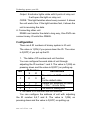
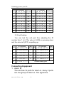
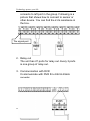
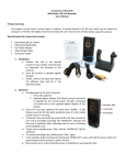
Technology protect your life
Alarm IO Control Unit
User Manual
(V1.0)
Interface Introduce
1.Power: indicator light of power
Code: indicator light of Communication
2.Alarm Input: 8 ports for alarm input
IN: the port for alarm signal input
: immonality port
www.uaichina.com
-1-
Technology protect your life
ID: the ID number of IO unit
RS485: the port of RS485 communication
DC 12V: the port of DC 12 volt input
ALARMS IN:indicator light of alarm in
3. Alarm output: 8 ports relay output
OUTPUT: relay output
NO: pot of relay continuous opening
NC: pot of relay continuous closing
C: relay commonality port
C-OUTPUT: relay commonality output port ALARMS
OUT:indicator light of relay output
Functions
1.Alarm input
There are 8 ports for alarm in. I will trigger alarm
whether the signal line is short circuit or open circuit. And
the indicator light will show red on alarm. It closes the
indicator light of alarm when stop alarm.
2. Relay output
There are 8 ports of relay output and one port of
commonality relay output. The unit can control every
relay output.
3. Indicator light
Input: 8 indicator lights relate with 8 ports of alarm in. It
will open the light on alarm in. For example, the
NO.1 light will be red when the first port is
alarming in.
www.uaichina.com
-2-
Technology protect your life
Output: 8 indicator lights relate with 8 ports of relay out.
It will open the light on relay out.
CODE: This light twinkles about every second. It shows
the unit works fine. If the light twinkles fast, it shows the
unit is receiving the data.
4. Connecting other unit
RS485 can transfer the data to long way, One DVR can
connect many IO units thru RS485.
Configuration
There are 8 ID numbers of binary system in IO unit.
The value is 1(ON) if you press down the ID. The value
is 0(OFF) if you put up the ID.
1. The table of ID number and unit function
You can configure the work state of unit through
adjusting the ID number 1 and 2. The value is 1(ON) on
pressing down and the value is 0(OFF) on putting up.
ID Number
NO
Unit function
1
2
The state of DVR controlling
1
0
0
unit
It is the default state.
2
1
0
It relays out automatic on alarm
in. it has 1 minute delay.
3
0
1
4
1
1
The state of testing unit
2.The table of ID number and unit address
You can configure the address of unit with adjusting
the ID number 5,6,7 and 8. The value is 1(ON) on
pressing down and the value is 0(OFF) on putting up.
www.uaichina.com
-3-
Technology protect your life
1
ID Number
Address NO
5 6 7 8
0 0 0 1
01
9
5 6 7 8
1 0 0 1
2
0 0 1 0
02
10
1 0 1 0
10
3
0 0 1 1
03
11
1 0 1 1
11
4
0 1 0 0
04
12
1 1 0 0
12
5
0 1 0 1
05
13
1 1 0 1
13
6
7
8
0 1 1 0
0 1 1 1
1 0 0 0
06
07
08
14
15
16
1 1 1 0
1 1 1 1
0 0 0 0
14
15
16
NO
ID Number
Address
09
3. IO unit testing
You can test the unit port thru adjusting the ID
number from 1 to 6. The value is 1(ON) on pressing down
and the value is 0(OFF) on putting up.
1
ID Number
Test
NO
1 2 3 4 5 6 7 8 Port
11XXX000
1
5
2
11XXX001
2
6
11XXX101
6
3
11XXX010
3
7
11XXX110
7
4
11XXX011
4
8
11XXX111
8
9
11XX1111
NO
ID Number
12345678
11XXX100
Test
Port
5
Commonality port
Connecting Equipment
1. Alarm IN
The unit has 16 ports for alarm in. Every 2 ports
are one group of alarm in. The signal line
www.uaichina.com
-4-
Technology protect your life
connects to left port in the group. Following is a
picture that shows how to connect to sensor or
other device. You can find the 2.2k resistance in
the box.
The signal port
NC
NO
2. Relay out
The unit has 27 ports for relay out. Every 3 ports
is one group of relay out.
3. Communication with DVR
It communicate with DVR thru RS232-RS485
converter.
www.uaichina.com
-5-
Technology protect your life
specification
Power:
Alarm IN:
Relay Out:
Relay power:
Temperature:
Humidity:
Dimension:
www.uaichina.com
DC12V 10W
NC or NO
NC or NO
8A/DC24V or 3A/AC220V
-1
¡Ü
90¨GRH
193(L)×120(W)×30(H)mm3
-6-