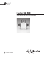
1
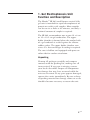
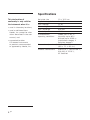
user manual SE 260 Hoefer SE 260 mini-vertical gel electrophoresis unit um SE260-IM/Rev. A0/05-04 Page finder 1. Gel Electrophoresis Unit Function . . . . . . . . . . . 1 and Description 2. Important information . . . . . . . . . . . . . . . . . . . . 4 3. Operating instructions . . . . . . . . . . . . . . . . . . . . 6 4. Care and maintenance . . . . . . . . . . . . . . . . . . 16 5. Troubleshooting . . . . . . . . . . . . . . . . . . . . . . . 17 Appendix Bibliography . . . . . . . . . . . . . . . . . . . . . . . . . . . 21 • pi • pii 1. Gel Electrophoresis Unit Function and Description The Hoefer™ SE 260 small format vertical slab gel unit is intended for rapid electrophoresis of protein or nucleic acid samples. Most samples can be run in as little as 45 minutes, and only a minimal amount of sample is required. The SE 260 accommodates one or two 10 × 8 cm or 10 × 10.5 cm gel sandwiches. The upper buffer chamber is formed when the notched side of a gel sandwich is sealed against the silicone rubber gasket. The upper buffer chamber core serves as a heat exchanger if cooling is required. The core is hollow and equipped with ports on either side for coolant circulation. Unpacking Unwrap all packages carefully and compare contents with the packing list, making sure all items arrived. If any part is missing, contact your local sales office. Inspect all components for damage that may have occurred while the unit was in transit. If any part appears damaged, contact the carrier immediately. Be sure to keep all packing material for damage claims or to use should it become necessary to return the unit. • p1 Specifications This declaration of conformity is only valid for the instrument when it is: • used in laboratory locations, • used as delivered from Hoefer, Inc. except for alterations described in the user manual, and • connected to other CE-labeled instruments or products recommended or approved by Hoefer, Inc. Gel plate size 10 × 10.5 cm Approximate gel size 8 × 9.5 cm Max. wattage 12 W Max. voltage 500 V Max. amperage 500 mA Max. temperature 45 °C Environmental operating conditions Indoor use: 4–40 °C Humidity up to 80% Altitude up to 2000 m Installation category II Pollution degree II Dimensions (w × h × d) 16.5 × 18 × 16 cm (6.5 × 7.1 × 6.3 in.) Product certifications • p2 EN61010–1, UL61010A–1, CSA C22.2 1010.1, CE Certified Fig 1. Main components SE 260 electrophoresis unit Color-coded leads (2) SE6056-HV Included but not shown: Safety lid SE256 Glass plates Notched alumina plates Gel seal, 1/4 oz. Spacer-Mate Well-locating decal Upper buffer chamber core SE254B Required but not included: Power supply with a minimum rating: 250 V, 50 mA, constant current or constant voltage Foam gasket SE208 SE 260 Lower buffer chamber SE255D Spring clamps (4) SE252 Coolant port (2) • p3 2. Important information English � � • The safety lid must be in place before connecting the power leads to a power supply. • Turn all power supply controls off and disconnect the power leads before removing the safety lid. • Circulate only water or 50/50 water/ethylene glycol through the heat exchanger. Never introduce antifreeze or any organic solvent into any part of the instrument. Organic solvents will cause irreparable damage to the unit! • Do not connect the heat exchanger to a water tap or any coolant source where the water pressure is unregulated. • Do not operate with buffer temperature above 45 °C. All plastic parts are rated for 45 °C continuous duty. Circulate coolant through the heat exchanger during electrophoresis to minimize heating. Additional passive cooling actions include chilling the buffer before use, running the unit in a cold room, or both. Overheating will cause irreparable damage to the unit! • If running only one gel, block off the unused part of the core with a glass plate. Do not fill this side with buffer. • Only accessories and parts approved or supplied by Hoefer, Inc. may be used for operating, maintaining, and servicing this product. • p4 Informations importantes • Le couvercle de sécurité doit être en place avant de brancher les prises au générateur. Français � � • Eteindre le générateur et débrancher les prises avant d’enlever le couvercle de sécurité. • Faire circuler seulement de l’eau ou 50/50 d’eau et d’éthylène glycol dans l’échangeur vertical à cirulation d’eau. Ne jamais utiliser d’anti-gel ou tout autre solvant organique avec cet instrument. Les solvants organiques causeraient des dommages irréparables à l’appareil. • Ne pas connecter l’échangeur vertical à circulation d’eau à un robinet ou quelque source de refroidissement dont la pression n’est pas régulière. • Ne pas utiliser avec un tampon à une température au dessus de 45 °C. Toutes les piéces en plastique sont prévues pour résister à une température constante de 45 °C. Faire circuler l’eau dans l’échangeur vertical durant l’électrophorèse pour minimiser l’échauffement. L’on peu aussi refroidir le tampon avant l’utilisation et/ou utiliser l’instrument dans une chambre froide. Un surchauffement peut causer des dommages irréparables à l’instrument. • Pour le coulage d’un seul gel, bloquer la parite de la chambre non utilisée avec une plaque de verre. Ne pas remplir le côté vide avec du tampon. • Seulement les accessoires et piéces detachées approuvés ou fournis par Hoefer, Inc. sont recommandés pour l’utilisation, l’entretien et réparation de cet appareil. • p5 3. Operating instructions 3.1 Prepare the gel sandwich Note: All electrophoresis accessories and kits are listed in the the ordering section. Both precast and self-cast gels can be run in the SE 260 units. For longer gel length, 10 × 10.5 cm plates, gels can be cast in the Hoefer SE 235 4-gel caster. The SE 260 can also accommodate shorter length gel in 10 × 8 cm plates, which can be cast in a Hoefer SE 215, SE 245, or SE 275 gel caster. Note: Inspect glass plates for chipped edges. Use only unchipped plates to prevent leaking. Each unit includes notched alumina plates and rectangular glass plates. If casting your own polyacrylamide gels, we recommend using a notched alumina ceramic back plate because it transfers heat 40 times more rapidly than glass. For applications that are not heat sensitive, a notched glass plate is available. Notched plate • p6 Before loading gels into the electrophoresis unit, the separating gel should already be completely polymerized. Clean away any gel adhering to the alumina back plate. The stacking gel (if applicable) can be cast in place on the electrophoresis unit. Load liquid samples after the gel sandwich is installed. 3.2 Prepare the unit To disassemble a fully assembled unit: Remove the safety lid by pressing on the handle at the top of the upper buffer chamber core while lifting the lid by the bottom edges. Empty all buffer chambers and remove any gel sandwiches. Then depress both release tabs and lift out the upper buffer chamber core. Rinse the instrument before each use. Before using the first time, disassemble the unit completely and wash with a dilute solution of a laboratory detergent and thoroughly rinse with water and distilled water. Check the gasket. Periodically remove the gray silicone rubber gasket from the core. Inspect for nicks and wear. If the gasket appears to be intact, apply a light film of Gel seal, and replace it in the groove. Avoid stretching the gasket by laying it onto the groove and pressing it into place. Optional cooling. Important! Use only water or water and ≤50% ethylene glycol as a coolant. Do not use a commercial antifreeze or any alcohol-based mixture. Note: If the cooling option is used frequently, it is convenient to attach QuickFit connectors to the tubing. The valves in these fittings prevent coolant spillage. Circulating pressure must not exceed 0.8 bar (12 psi) above ambient pressure. Do not connect the cooling core to an unregulated coolant source such as a water tap. Connect the cooling core to a circulator bath such as the MultiTemp III. Slide hose clamps (4 total) onto each end of two lengths of 8 mm (5/16”) vinyl or silicone tubing. Attach one end of each length of tubing to a cooling core port. Attach the free ends of each length of tubing to the circulator bath ports; one to the inlet and the other to the outlet. Secure the connections with the hose clamps. • p7 Install the upper buffer chamber core. First steady the lower chamber with one hand and then hold the core with the other hand, position it on the positioning tabs, and press down, listening for the core to snap into place. (Alternatively, depress both release tabs at either side, position the core on the positioning tabs, press into place, and release the tabs. Check that the core is secure.) Fig 2. Core installation and removal. Handle To remove the core, depress both release tabs and lift. Release tabs (2) Coolant port (2) To install the core, position it over the positioning tabs. Then either press down, listening for the core to snap into place — OR — depress both release tabs, set the core in place, and release. • p8 3.3 Place the gel sandwich Fig. 3a–b. Gel sandwich installation. Rinse away the overlay with distilled water and drain any excess water. If installing a self-cast or precast 10 × 8 cm gel sandwich, align the bottom of the plate with the bottom of the core. (Fig. 3a) The bottom of the notched plate must cover the silicone rubber gasket. Fig 3a. A 10 × 8 cm gel sandwich fits flush with the bottom of the upper buffer chamber core. If installing a self-cast or precast 10 × 10.5 cm gel sandwich, orient the sandwich so that the notched plate faces the gasket, notches at the top. Set the bottom of the sandwich on the supporting ledges in the bottom of the lower chamber and center the plate so that the gasket seals both sides. (Fig. 3b) Fig 3b. A 10 × 10.5 cm gel sandwich fits against the bottom of the lower buffer chamber. • p9 Clamp the sandwich in place Lightly press the sandwich against the gasket and secure it to the core with one spring clamp on each side. Position the jaw so that the shorter rounded jaw edge fits into the core groove and the longer edge sits on the glass plate. (Proper positioning is important to achieve a seal and to minimize glass breakage.) Slide the clamps down to the stop. Fig 4. Securing the gel sandwich onto the upper buffer chamber core Each sandwich requires two clamps. The rounded edge of the short jaw on the clamp fits into the groove behind the gasket, and the long jaw presses on the glass plate over the spacer. Repeat step 1 for the second sandwich, or, if running only one gel, clamp a plain glass plate on the unused side of the core to prevent a possible short circuit with the unused electrode. (Do not fill this chamber with buffer if no gel sandwich is in place.) Fit short jaw of clamp into the groove Cooling is optional: Attach tubing to ports on both sides of the core before attaching gel sandwiches. Circulate coolant. • p10 3.4 Sample preparation and loading If wells are already in place, skip to step 2. If applicable, cast the stacking gel in the unit. Note: Stacking gel resolution is optimal when poured just before electrophoresis. Calculate the stacking gel monomer solution volume: measure the distance, in cm, from the top of the resolving gel to the notch in the alumina plate. (This should be at least 2 cm—more if the sample depth in the well is unusually high.) Multiply this distance by the gel width (8.3 cm) and the gel thickness (cm). This product is the required volume in ml. Deaerate the stacking gel monomer solution, add catalyst and initiator and then pour. Use a pipette to deliver the solution into one corner of the plate, taking care not to trap any bubbles. Insert a comb (at a slight angle to prevent trapping air) into the sandwich, allowing the comb sides to rest on the spacers. Prepare the sample. Increase liquid sample density with 10% glycerol or sucrose. Add a tracking dye such as phenol red or bromophenol blue. For SDS protein gels, use 2X treatment buffer to denature both liquid and dry samples in a test tube. To liquid protein solutions, add an equal volume of 2X buffer. To dry protein samples, add equal volumes of buffer and ddH2O to achieve the desired concentration. Heat the tube in boiling water for 90 seconds, then chill it in ice until ready to use. Treated samples can be stored frozen for future runs. (Store at -40 °C to -80 °C.) To aid in loading samples, wet the well-locating decal and apply it to the front of the glass plate so that the appropriate edge outlines the sample wells. Note: The side wells for standards of a preparative comb correspond to the outer-most wells formed by the 10-well comb. • p11 Fill the sample wells and each upper buffer chamber that will be used with running buffer. One upper buffer chamber holds approximately 75 mL. Note: The amount of protein sample added to each well depends on both the sensitivity of the staining method and the distribution of protein among separate bands. With Coomassie™ Blue, it is possible to detect 1 µg in a single band; with the more sensitive silver stains, it is possible to detect as little as 10 ng. Underlay the sample into the wells using a fine-tipped microsyringe. The width of the wells depends on the number of wells per comb. If the comb has fewer wells, they are wider, and require more volume to raise the level 1 mm, as shown in the following table. Volume of sample (µL) per 1 mm depth no. of wells 5 vcomb thickness (mm) 0.75 1.0 1.5 9.5 12.7 19.1 9 10 3.6 4.8 7.2 15 2.2 2.9 4.4 18 • p12 5.8 2.9 3.5 Final assembly Fill the lower buffer chamber with running buffer. The SE 260 holds about 250 mL. Check that the lower electrode (running along the bottom of the the upper buffer chamber core) is completely submerged. Note: If using precast gels, check that the lower gel/ buffer contact surface is exposed (the colored plastic tape must be removed.) Place the safety lid on the unit. Important! Do not use antifreeze or any alcohol-based mixture, as these will irreparably damage the core. Plug the color-coded leads into the jacks of an approved power supply such as the EPS 2A200. The red lead plugs into the red output jack, and the black lead plugs into the black output jack. Optional cooling: Begin circulating cold water or a chilled 50/50 water/ethylene glycol solution. • p13 3.6 Running the Gel Gels may be run at either constant current or constant voltage. A constant current setting is traditionally used with a discontinuous buffer system so that the rate of electrophoretic migration remains unchanged throughout the run. Under these conditions, voltage increases as the run proceeds. A lower current setting is recommended for higher resolution. Precast gels are run under the same current and voltage conditions as self-cast gels. Important! After initial monitoring, do not leave the unit unattended for more than 45 minutes before checking the progress of the the bands and the buffer level. • p14 It takes about one hour to run two 7 cm × 0.75 mm Laemmli gels at 40 mA (20 mA per gel, constant current). Check band progress after 5 minutes, and again after half an hour, keeping an eye on the position of the tracking dye. The run is complete when the tracking dye reaches the bottom of the gel. Watch the buffer level in the upper buffer chamber and, if necessary, replenish it before it falls below the level of the notched plate. (A small volume of buffer may leak past a chipped plate or nicked gasket, or it may wick out through the gel.) After the run Important! Always disconnect the high voltage leads from the power supply before removing the lid from the unit. Once the tracking dye reaches the bottom of the gel, turn off the power supply, disconnect the leads, and remove the safety lid. If coolant is circulating, stop the flow and disconnect the fittings or tubing. Remove the core assembly with gels attached by squeezing the release tabs and lift out the core assembly. Pour out the buffer by inverting the core assembly, then remove both clamps, and lift away gel sandwich(es) from the upper buffer chamber core. Gently loosen and then slide away both spacers. Slip an extra spacer or a Hoefer Wonder Wedge into the bottom edge (to prevent breaking the ears of the notched plates) and separate the plates. The gel usually adheres to the alumina plate. Carefully lift the gel from the plate and lay it into a tray of stain or fixative. • p15 4. Care and maintenance • Do not autoclave or heat any part above 45 °C. • Do not use organic solvents, abrasives, strong cleaning solutions, or strong acids or bases to clean the chambers. Immediately after each use, rinse the unit with water and then rinse thoroughly with distilled water. Handle the upper buffer chamber core with care to prevent damage to the banana plugs. Allow to air dry. Clean glass and alumina plates and spacers with a dilute solution of a laboratory cleanser such as RBS-35™, then rinse thoroughly with tap and distilled water. Glass plates can also be treated with (but not stored in) acid cleaning solutions. • p16 5. Troubleshooting problem solution Smile effect on the buffer front To reduce the running temperature: Circulate coolant through the upper buffer chamber core. Prechill the buffer. Decrease the current or voltage setting. (10 mA per 0.75 mm gel, 15 mA per 1.5 mm thick gel.) Run the gel in the cold room. Protein streaks vertically Centrifuge or filter sample before loading to remove particulates. Dialyze or desalt the sample. Unusually slow (or fast) run Adjust the solutions: Check recipes, gel concentrations, solutions, and dilutions. (For instance, do not use Tris™-HCl instead of Tris.) If the required pH of a solution is exceeded, do not back-titrate. Prepare fresh buffer. Dispose of older acrylamide solutions and use only stock of the highest quality. Only use freshly deionized urea. Adjust the voltage or current settings: To increase or decrease the migration rate, adjust the voltage or current by 25–50%. Bands are skewed or distorted Check gel preparation and polymerization Degas the stacking gel solution and avoid trapping air bubbles under the comb teeth. Overlay the running gel with water-saturated n-butanol before polymerization begins to avoid forming an uneven gel surface. Check sample preparation Dialyze or desalt the sample. Centrifuge or filter sample before loading to remove particulates. • p17 problem solution Stained sample collects: Near the buffer front Protein is not sufficiently restricted by the resolving gel; increase the % T. Near the top of the gel when the buffer front has reached the bottom The gel pore size is too small. Decrease the % T of the resolving gel. The protein has precipitated. Heat the sample at a lower temperature (70 °C or less) for 1–2 minutes. Poor band resolution Use only the highest quality reagents. Conduct the separation at a lower current or voltage setting. Dialyze or desalt the sample. Reduce the sample volume or concentration. Only use freshly deionized urea. Improve dissociation of subunits by heating sample in SDS sample buffer 1–2 minutes at 100 °C. Add more mercaptoethanol or dithiothreitol; check sample treatment. Only use gels that were recently prepared. Check pH values of the separating and stacking gel solutions. Do not back-titrate buffers. Sample preparation Heat samples for no more than 1–2 minutes at 100 °C. Store on ice after heating. Store sample on ice before it is denatured. Add protease inhibitors if necessary to prevent proteolytic degradation of sample. Store samples to be frozen in aliquots to prevent repeated freezing and thawing. (Store at -40 °C to -80 °C.) Bromophenol blue doesn’t sharpen into a concentrated zone in the stacking gel Pour a taller stacking gel. (For best results, allow a stacking gel height of 2.5 times the height of the sample in the well.) Dispose of outdated acrylamide solutions and use only the highest grade of acrylamide. When preparing samples, avoid using solutions with a high sodium or potassium concentration. • p18 Appendix The following Laemmli system is slightly modified for use with the mini-vertical units. The Laemmli system is the most common electrophoresis protocol for SDS-denatured proteins. The leading ion in this discontinuous buffer system is chloride and the trailing ion is glycine. Accordingly, the resolving gel and the stacking gel contain Tris-Cl buffers (of different concentration and pH), and the electrophoresis buffer contains Tris-glycine. All buffers contain 0.1% SDS. Polyacrylamide gel composition is indicated by two different percentages: % T = total acrylamide = g (acryl + bis) × 100 100 mL % C = crosslinker = SE 260 results: Lane 1: SDS-6H, high MW standard mixture, Sigma™ Lane 2: SDS-7 Dalton Mark VII-L™, Sigma (10 µl per lane) g (bis) × 100 g (acryl + bis) The total percent of acrylamide (% T) in the separating gel, which can range from 5 to 20%, determines the pore size. Commonly, the amount of crosslinker used (% C) is 2.6%. In the following example system, the resolving gel composition is 10% T, 2.6% C, which results in a medium pore size. The stacking gel composition is 4% T, 2.6% C. The % T in the stacking gel is lower because a larger pore size is required. Gel 12% SDS PAGE Stained with Coomassie Blue Running conditions 20 mA, one hour • p19 Final concentrations separating gel stacking gel Acrylamide conc. 10% T*, 2.6% C 4% T, 2.6% C Tris-Cl 0.375 M 0.125 M Tris-glycine electrophoresis buffer 0.025 M Tris base 0.192 M glycine pH 8.8 6.8 ~8.3 SDS 0.1% 0.1% 0.1% Ammonium persulfate (APS) 0.05% w/v 0.05–0.1% w/v TEMED† 0.05% v/v 0.05–0.1% v/v *To achieve any other desired final concentration, adjust the acrylamide stock and water volumes. †Tetramethylethylenediamine • p20 Bibliography Adams, L.D. and Gallagher, S.R., Two-Dimensional Gel Electrophoresis Using the O’Farrell System. Current Protocols in Molecular Biology, 10.4.1– 10.4.13 (1992). Gallagher, S.R., and Smith, J.A., Electrophoretic separation of proteins. Current Protocols in Molecular Biology. (F.A. Ausubel, R. Brent, R.E. Kingston, D.D. Moore, J.G. Seidman, J.A. Smith, and K. Struhl, eds.) 10.2.1–10.2.21 (1991). Laemmli, U.K., Cleavage of structural proteins during the assembly of the head of bacteriophage T. Nature. 227, 680–685 (1970). Matsudaira, P.T. and Burgess, D.R., SDS microslab linear gradient polyacrylamide gel electrophoresis. Anal. Biochem. 87, 386–396 (1978). Reisfeld, R.A., et al. Acidic buffer system for resolution of cationic proteins. Nature. 195, 281 (1962). Sasse, J., and Gallagher, S.R., Staining proteins in gels. Current Protocols in Molecular Biology. (F.A. Ausubel, R. Brent, R.E. Kingston, D.D. Moore, J.G. Seidman, J.A. Smith, and K. Struhl, eds.) 10.6.1–10.6.8 (1991). Towbin, H., et al. Electrophoretic transfer of proteins from polyacrylamide gels to nitrocellulose: procedure and some applications. Proc. Natl. Acad. Sci. USA. 76, 4350–4353 (1979). Weber, K., and Osborn, M., The reliability of molecular weight determinators by dodecyl sulfate-polyacrylamide gel electrophoresis. J. Biol. Chem. 224, 4406–4412 (1969). • p21 • p22 Ordering information product quantity code number Mini-Gel System Hoefer SE 260 1 SE260-10A-.75 Foam gasket, 4.5 mm × 61 cm 1 SE208 Upper buffer chamber for SE 260 1 SE254B Deep lower buffer chamber for SE 260 1 SE255D Lid with cables for SE 260 1 SE256 Wonder Wedge plate separation tool 1 SE1514 High voltage safety lead set 1 SE6056-HV Gel Seal (0.25 oz) 1 SE6070 Spring clamps, for SE 260 and gel casters 4 SE252 Well locating label 2 SE212 Mini-Vertical Unit for 2 slab gels, Complete Includes: basic unit, 10 glass plates (10 × 10.5 cm), 2 alumina notched plates, well-locating decal, Spacer-Mate assembly template, SE 245 Dual Gel Caster, 2 each 0.75-mm thick 10-well combs and 0.75-mm thick spacer sets. Electrophoresis Unit Replacement Parts Glass and Alumina Plates 10 × 8 cm Notched alumina plates Rectangular glass plates 10 10 10 × 10.5 cm Notched alumina plates Rectangular glass plates 5 5 SE202N-10 SE202P-10 SE262N-5 SE262P-5 • p23 product quantity code number Spacers thickness (mm) length (cm) 0.75 8 2 SE2119T-2-.75 1.00 8 2 SE2119T-2-1.0 1.50 8 2 SE2119T-2-1.5 0.75 10.5 2 SE2619T-2-.75 1.00 10.5 2 SE2619T-2-1.0 1.50 10.5 2 SE2619T-2-1.5 no. well thickness (mm) width (mm) 5 0.75 13.0 1 SE211A-5-.75 5 1.00 13.0 1 SE211A-5-1.0 Teflon Combs 5 1.50 13.0 1 SE211A-5-1.5 9a 1.00 5.8 1 SE211A-9-1.0 10 0.75 4.8 1 SE211A-10-.75 10 1.00 4.8 1 SE211A-10-1.0 10 1.50 4.8 1 SE211A-10-1.5 15 0.75 2.9 1 SE211A-15-.75 15 1.00 2.9 1 SE211A-15-1.0 15 1.50 2.9 1 SE211A-15-1.5 18 1.00 2.9 1 SE211A-18-1.0 1/1b 0.75 68/5 1 SE211A-R-.75 1/1b 1.00 68/5 1 SE211A-R-1.0 1/1b 1.50 68/5 1 SE211A-R-1.5 a a Microtiter spacing, b Preparative/reference well • p24 product quantity code number Gel Casters For 1 or 2 gels, 10 × 8, -10.5 Hoefer SE 245 Dual Gel Caster For 5 to 10 gels, 10 × 8 cm 1 SE245 Hoefer SE 215 Multiple Gel Caster, Complete 1 Includes: 20 rectangular glass plates, 10 notched alumina plates, 100 sheets of wax paper, space saver plate, 5 filler sheets, set of filler plugs and Spacer-Mate. (Order combs and spacers separately.) For 2 to 4 gels, 10 × 8 cm SE215 Hoefer SE 275 4-Gel Caster, Complete SE275 1 Includes: 10 rectangular glass plates, 4 notched alumina plates, 100 sheets of wax paper, space-saver plate, 5 filler sheets, Spacer-Mate and filler plugs. (Order combs and spacers separately.) For 2 to 4 gels, 10 × 10.5 cm Hoefer SE 235 4-Gel Caster, Complete 1 SE235 Includes: 4 notched alumina plates, 5 rectangular glass plates, 100 sheets wax paper, space saver plate, 5 filler sheets, set of filler plugs and Spacer-Mate assembly template.(Order combs and spacers separately.) Power Supplies Hoefer EPS 2A200 1 PSA2A200 Hoefer SE 100 PlateMate washing and storage unit 1 SE100 TE 22 Transphor Tank Unit 1 TE22 QuickFit connector, male, 3/8” 1 QFX3/8 Miscellaneous • p25 • p26 Printed in the USA Hoefer, Inc. 953 Indiana Street San Francisco, CA 94107 USA www.hoeferinc.com