1
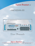
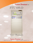
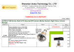
Superior Broadcast LLC ATSC 3000 Exciter User Manual Superior Broadcast LLC 1 8 2 0 8 P r e s t o n R d . S u i t e D 9 - 2 9 7 , D a l l a s , T X 7 5 2 5 2 . w w w. s b p - t v. c o m Superior Broadcast ATSC 3000 Exciter S u p e r i o r B ro a d cast where the B est Cost L ess C a l l u s t o d a y. We want to talk to You Superior Broadcast LLC 18208 Preston Rd. Suite D9-297, Dallas, TX 75252 Tel: 972-473-2577 | Email: [email protected] www.sbp-tv.com All rights reserved. Printed and bound in the U.S.A . No part of this manual may be reproduced, memorized or transmitted in any form or by any means, electronic or mechanic, including photocopying, recording or by any information storage and retrieval system, without written permission of the copyright owner. ATSC 3000 Exciter User Manual 2 Superior Broadcast Superior Broadcast ATSC 3000 Exciter ATSC3000 Exciter User Guide Contents 1 Product Appearance ............................................................................................3 1.1 Front Panel .......................................................................................................3 1.2 Back Panel .......................................................................................................3 2 Operation Specifications.....................................................................................4 3 Menu ...................................................................................................................6 3.1 Initialization .....................................................................................................6 3.2 Query Mode .....................................................................................................6 3.3 Control Mode ...................................................................................................6 4.1 Connect the Transmitter.................................................................................10 4.2 Start ADPC function ......................................................................................10 5 Troubleshooting ................................................................................................12 5.1 Input ...............................................................................................................12 5.2 ADPC .............................................................................................................12 5.3 Other Problems ..............................................................................................13 Version 2.0 Superior Broadcast 10/23/2012 3 Page 2 of 13 ATSC 3000 Exciter User Manual Superior Broadcast ATSC 3000 Exciter ATSC3000 Exciter User Guide 1 Product Appearance 1.1 Front Panel LCD: 40×2 LCD with power saving backlight Reset button: RST: System reset button 6 Buttons : Left, Right, Up, Down, OK, Esc (from left to right) 6 LEDs: LED_TS1: Green light on indicates TS1 is selected and the input TS signal is OK LED_TS2: Green light on indicates TS2 is selected and the input TS signal is OK LED_TSErr: Red light on indicates the selected input signal has error (Refer to Chapter 5) LED_ GPS: Green light on indicates 10 MHz reference signal connected and locked LED_ RFON: Green light on indicates system ready and RF on LED_ SysErr: Flashing of the red light indicates some system error (Refer to Chapter 5) Red light on indicates it's in "Local (LCL)" control mode, and red light off indicates it's in "Remote (RMT)" control mode 1 BNC connector: RFMON: Loop out of feedback signal from port [RF_IN_A] for monitoring 1.2 Back Panel RF_IN_A: RF_IN_B: RF_MON: RF_OUT: TOD_IN (RS232): REMOTE (RS232): REMOTE (RJ45-B): TSoIP (RJ45-A): 10M_IN: 1PPS: TS_IN_1: TS_OUT_1: TS_IN_2: TS_OUT_2: Feedback signal after band-pass filter Feedback signal before band-pass filter Loop out of [RF_OUT] for monitoring RF signal output Reserved Serial port for remote control 10M/100M Ethernet for remote control Reserved 10 MHz input from external GPS receiver 1 PPS input from external GPS receiver The first input for TS signal, ASI only Loop out of [TS_IN_1] for monitoring The second input for TS signal, ASI only Loop out of [TS_IN_2] for monitoring Version 2.0 10/23/2012 ATSC 3000 Exciter User Manual Page 3 of 13 4 Superior Broadcast Superior Broadcast ATSC 3000 Exciter ATSC3000 Exciter User Guide 2 Operation Specifications Environment Operating Temperature: Operating Humidity: Atmospheric Pressure: Power Supply Voltage: Frequency: Inputs/Outputs RF_IN_A /RF_IN_B Connector: Impedance: Level: -10 ~ 50 oC ≤ 95% 86 kPa ~ 106 kPa 88 ~ 264 VAC 50 / 60 Hz BNC female 50 Ω -30 dBm ~ 0 dBm Recommended range: -15 dBm ~ -5 dBm Back Panel Location: RF_OUT Connector: N-type female Impedance: 50 Ω Level: -25 dBm ~ +5 dBm VSWR: > 15 dB Location: Back Panel RF_MON (loop out of [RF_OUT]) Connector: BNC female Impedance: 50 Ω Level: -25 dB below [RF_OUT]'s output level Location: Back Panel 10M_IN Connector: BNC female Impedance: 50 Ω Level: AC-coupled, VP-P ≥ 300 mV Location: Back Panel 1PPS (input) Connector: BNC female Impedance: 50 Ω Level: 3.3 V-TTL Input trigger: Positive Transition Location: Back Panel TS_IN_1/ TS_IN_2 Connector: BNC female Impedance: 75 Ω Level: See Table 1 Version 2.0 10/23/2012 Superior Broadcast Page 4 of 13 5 ATSC 3000 Exciter User Manual Superior Broadcast ATSC 3000 Exciter ATSC3000 Exciter User Guide Location: Back Panel TS_OUT_1/ TS_OUT_2 Connector: BNC female Impedance: 75 Ω Location: Back Panel RF_MON FEEDBACK (loop out of [RF_IN_A]) Connector: BNC female Impedance: 50 Ω Level: -11 dB below [RF_IN_A]'s output level Location: Front Panel Table 1 ASI Input Specifications No Content Unit Value 1 Input Level mv ≥ 200 2 Positive Transition (20%~80%) ps ≤ 1200 3 Negative Transition (20%~80%) ps ≤ 1200 4 Deterministic Jitter % ≤ 10 5 Random Jitter % ≤8 Note 1) The interface electrical characteristics are measured under normal condition. Otherwise the values may change. 2) Operating under abnormal circumstances may cause dysfunction of the exciter. Long operating hours under severe environment may reduce the reliability of the entire system, which even causes permanent damage to electronic components. Ensure all interface electrical characteristics or environment parameters are within the defined range listed above before any operation. Version 2.0 10/23/2012 ATSC 3000 Exciter User Manual Page 5 of 13 6 Superior Broadcast Superior Broadcast ATSC 3000 Exciter ATSC3000 Exciter User Guide 3 Menu 3.1 Initialization Connect power supply then turn on the exciter. The initialization process takes about 5 seconds to finish while RF output level increases gradually to the pre-set value. 3.2 Query Mode Query mode is a mode which displays parameters and status of exciter. There are three pages in query mode. Press "Right" or "Left" button to switch between different pages which are shown from Table 2 to Table 4 as below. Note: All the displayed settings or numbers in below tables are for illustration only and may be different from those in actual use. Table 2 the First Page in Query Mode TSNR LID UID 38.5 43.5 44.0 Table 3 the Second Page in Query Mode INPUT STA TS_RATE TEMP TS1 OK 19.392816 Mbps 104.90℉ Table 4 the Third Page in Query Mode FREQ AGC GPS 1PPS CTRL ADPC 683M OFF LOCK OK RMT OFF Note: 1) The "TSNR", "LID" and "UID" in Table 2 are the measurement of feedback signal quality. This feedback signal could be from a transmitter or the exciter itself and its input range is from -30 dBm to 0 dBm (Recommended range is -15 dBm to -5 dBm). Feedback signal is required to be connected port [RF_IN_A] ONLY. If there is no signal connected, these readings will not be available or not valid. The "TSNR" is measured with equalization on. It takes about 10 seconds to get the first reading on "TSNR", and about 3 seconds to get the first reading of "LID" and "UID". After averaging, the "TSNR" display upper limit is shown at about 39 dB and those of IMD are shown at about 54 dB. 2) The "CTRL" status in Table 4 has "RMT" (Remote) mode and "LCA" (Local) mode. When in "Local" mode, the exciter can only be controlled by the front panel interface and when in "Remote" mode, settings from the front panel keyboard are ignored - with the exception of "RMT"/"LCA" setting, and only commands from remote control interface, such as serial port or WEB, are processed. 3.3 Control Mode Control mode is a mode to specify settings of exciter. To switch to control mode, press both Version 2.0 10/23/2012 Superior Broadcast Page 6 of 13 7 ATSC 3000 Exciter User Manual Superior Broadcast ATSC 3000 Exciter ATSC3000 Exciter User Guide "Left" and "Right" buttons at the same time in query mode. Main menu in control mode is shown in Table 5. Table 5 Main Menu in Control Mode Welcome to setting interface! *SYSTEM RF MODE CONFIG Main menu consists of 4 sub-menus: SYSTEM, RF, MODE and CONFIG. When on main menu in control mode, press "Left" or "Right" button to move the cursor and press "OK" button to enter the target sub-menu. When in the corresponding sub-menu, press "Left" or "Right" button to move the cursor to the target parameter and then press "Up" or "Down" button to select options from the drop-down boxes. Press "OK" button to save, or press "ESC" button to skip the changes and return to upper menu. All the parameters of sub-menus are shown from Table 6 to Table 9 respectively. Table 6 System Menu in Control Mode Default Options CTL ADPC RST RMT OFF NO RMT OFF NO LCA UPDATE YES HOLD Note: 1) The "CTL" (Control) setting has two options, "RMT" (Remote) and "LCA" (Local). The exciter can be switched between these two modes only via the front panel interface. When in "LCL" mode, the exciter can only be controlled by the front panel interface and all commands from serial port or WEB are ignored. When in "RMT" mode, settings from the front panel keyboard are ignored - with the exception of "RMT"/"LCA" setting, and only commands from remote control interface, such as serial port or WEB, are processed. The default value of "CTL" after "RST" is "RMT". Notice that LED "SysErr" remains on all the time in "LCA" mode, so only when it is flashing means there is some system error. 2) The "ADPC" parameter in "SYSTEM" sub-menu has options of "UPDATE", "HOLD" and "OFF". If option "OFF" is selected, the ADPC function will be turned off. If option "HOLD" is selected, it will restore the last time stored ADPC data instead of restarting a new ADPC process. If feedback signal are connected properly and option "UPDATE" is selected, it will start a complete ADPC function, including both the linear and non-linear pre-correction to the entire transmission system including the distortion of both transmitter and band-pass filter. Refer to Chapter 4 for detailed information. 3) The "RST" parameter in "SYSTEM" sub-menu has options "YES" and "NO". There will be a check page out to confirm the operation in order to avoid any mistake happening. If option "YES" on the check page is selected, the system will restore all default settings. This may lead to the change of exciter's output level (the default value is 0 dBm after reset). To prevent any potential damage, disconnect all other device when the exciter is going to be reset. Version 2.0 10/23/2012 ATSC 3000 Exciter User Manual Page 7 of 13 8 Superior Broadcast Superior Broadcast ATSC 3000 Exciter ATSC3000 Exciter User Guide Table 7 RF Menu in Control Mode *RF FREQ Hz POWER AGC ON 707M +00000 +0.00 OFF ON 473M -50000 -25.00 OFF OFF 479M -49999 -24.95 ON 485M -49998 -24.90 ... ... ... ... ... ... ... ... ... 875M +49998 +4.90 881M +49999 +4.95 887M +50000 +5.00 Default Options Note: 1) The "Hz" parameter in "FREQ" sub-menu is the direct adjustment of the frequency of RF output signal. The range is -50,000 Hz to +50,000 Hz, with steps of 1 Hz. This feature is designed for up to 50 kHz spectrum shift as ATSC standard required, or adjustment of the output frequency for carrier accuracy. 2) The "AGC" parameter in "RF" sub-menu has options "ON" and "OFF". If option "ON" is selected, the AGC function will be turned on. This function ensures a stable output level of exciter even under the variation of working temperature or mismatch impedance, and its adjustable range is from +1 dB to -10 dB. If AGC function is turned on, it is not suggested to change other settings of the exciter, such as output level or channel. Only use the AGC function when the exciter or the entire transmitting system has been stable. Table 8 MODE Sub-menu in Control Mode 8VSB Table 9 CONFIG Menu in Control Mode Defa ult Optio *ID bps IP GATEWAY MASK UPGRADE ID: 80H 19200 192.168.001. 143 192.168.001.00 1 255.255.255.00 0 NO 19200 ***.***.***. *** ***.***.***.** * ***.***.***.** * NO ID: 80H ID: 00H ... ns 9600 YES 38400 ID: FEH ID: FFH Version 2.0 10/23/2012 Superior Broadcast Page 8 of 13 9 ATSC 3000 Exciter User Manual Superior Broadcast ATSC 3000 Exciter ATSC3000 Exciter User Guide Note: 1) "UPGRADE" is a mode to upgrade the firmware of micro controller. It’s only available for advanced users. If there is any misoperation, restart the exciter to cancel the upgrade process. 2) "IP", "GATEWAY", and "MASK" are used to establish a valid Ethernet connection for remote control via RJ45. The exciter has a built-in WEB GUI which requires only a standard web browser run by a PC. Simply by entering specified IP address, which is setup in CONFIG sub-menu, in a browser’s address bar, the login interface will pop up and give user prompts to input user name and password. Both the default user name and password are "admin" (case sensitive). The "admin" account only allows users to retrieve information such as SNR and shoulder measurements, user configuration, and alarms. Only some basic settings such as RF switch, Power, are accessible in "admin" account. To get a full control of the exciter, please log in with the root account, whose user name and password are "user" and "ANWP" (case sensitive). Version 2.0 10/23/2012 ATSC 3000 Exciter User Manual Page 9 of 13 10 Superior Broadcast Superior Broadcast ATSC 3000 Exciter ATSC3000 Exciter User Guide 4 Connection 4.1 Connect the Transmitter Don’t turn on or off the exciter when the transmitter is running. The correct order is: First of all turn on the exciter. Measure the RF output level of the exciter to make sure it meets the requirement of the transmitter input level. If the output level is out of range, change the parameter "POWER" in "RF" sub-menu in control mode to make the adjustments. Refer to Table 7, Chapter 3 for details. If the output signal level is within range, connect the exciter's output (port [RF_OUT] on back panel) to the transmitter's input. After the exciter is stable, turn on the transmitter. Likewise, turn off the transmitter first before making any change to the exciter's settings. Restart the transmitter after the exciter is stable again. 4.2 Start ADPC function After the exciter is connected to a transmitter, first of all measure the level of the transmitter's output (both before and after band-pass filter). Make sure it meets the requirement of exciter's feedback level (-30 dBm ~ 0 dBm and recommended range is -15 dBm to -5 dBm). If the signal level is out of range, use extra devices, e.g. attenuator, to make adjustments. If the signal level is within the range, connect the transmitter's output which is before band-pass filter to port [RF_IN_B] and another output which is after band-pass filter to port [RF_IN_A] respectively. Figure 1 below demonstrates the correct connection. Start ADPC function Select option "UPDATE" on "ADPC" of SYSTEM sub-menu in control mode. Save the change, then all 3 parts of the ADPC process starts automatically in sequence, with tips ("Wait a moment...") and readings of "TSNR", "LID" and "UID" shown on LCD. Usually it takes about 10 minutes to finish the total compensation of both the linear and non-linear distortion in the whole transmission system including both power amplifier and band-pass filter. Following each part, there is a "Saving" process which takes from seconds to minutes to save necessary ADPC data into the on-board memory. Readings of "TSNR", "LID" and "UID" provide a continuous measurement and display of quality of feedback signal during the ADPC process. Compare these readings before and after the ADPC process as the reference of compensation performance. Restart or abort the ADPC progress if compensation doesn't bring up a better signal quality. There is a "Loading" process if the exciter is turned on again or "HOLD" option is selected. It mainly restores the ADPC data saved last time when an entire ADPC process has been run successfully. Note: 1) To monitor the entire process, connect the output of [RF_MON FEEDBACK] which is on front panel) to equipment for measurement. The level of [RF_MON FEEDBACK] is about 11 dB lower than the feedback signal which is connected to port [RF_IN_A]. 2) Do not change the connection status during the ADPC process otherwise it may affect the Version 2.0 10/23/2012 Superior Broadcast Page 10 of 13 11 ATSC 3000 Exciter User Manual Superior Broadcast ATSC 3000 Exciter ATSC3000 Exciter User Guide 3) performance. If any abnormal situation occurs during the ADPC process, the system will bypass all the pre-correction data immediately and leave the corresponding tips on LCD. Press any key to cancel the ADPC function manually and restart the ADPC function again after the problems are resolved. Refer to Chapter 5 for further information. Before BPF After BPF Tx Antenna Attenuator1 Attenuator2 Transmitter RFINA ATSC Exciter/Translator RFOUT RFINB Power Amplifier RF_OUT Band-pass Filter Figure 1 Connection with Transmitter of UPDATE Function Version 2.0 10/23/2012 ATSC 3000 Exciter User Manual Page 11 of 13 12 Superior Broadcast Superior Broadcast ATSC 3000 Exciter ATSC3000 Exciter User Guide 5 Troubleshooting 5.1 Input TS1 ERROR Alarm message LCD: TS1 ERR LED_ TS1: Off LED_ TSErr: On Cause: Input signal from port [TS_IN_1] is lost or has invalid format. Solution: Check connection of port [TS_IN_1], and make sure input signal has valid format. TS2 ERROR Alarm message LCD: TS2 ERROR LED_ TS2: Off LED_ TSErr: On Cause: Input signal from port [TS_IN_2] is lost or has invalid format. Solution: Check connection of port [TS_IN_2], and make sure input signal has valid format. Transport Stream Rate Overflow or Underflow Alarm message LCD: TS_RATE Overflow Cause: The input TS bit rate is higher than the bit rate required Solution: Adjust the TS input bit rate. Or connect all devices with the same reference clock (GPS). Note: The exciter has bit rate auto-adaptation function to deal with the bit rate mismatch. It will automatically delete null packets or insert null packets when necessary to achieve the accurate acquired bit rate. 5.2 ADPC Feedback Signal Level Alarm message LCD: " FEEDBACK TOO BIG! Press Any key to Esc" Or " FEEDBACK TOO SMALL! Press Any key to Esc" LED_ SysErr: Flashing (during the ADPC process) Cause: Feedback signal level is too high or too low. Solution: Cancel the ADPC function manually and then adjust the input level of the feedback signal according to the messages on the LCD. Start the ADPC function again after the problem is resolved. Note: The acceptable range of feedback signal from port [RF_IN_A] or [RF_IN_B] is -30 Version 2.0 10/23/2012 Superior Broadcast Page 12 of 13 13 ATSC 3000 Exciter User Manual Superior Broadcast ATSC 3000 Exciter ATSC3000 Exciter User Guide dBm to 0 dBm, and the recommended range is from -15 dBm to -5 dBm. Feedback Signal Connection Error Alarm message LCD: FEEDBACK LINK ERROR! Press Any key to Esc LED_ SysErr: Flashing (during the ADPC process) Cause: Feedback signal connection is interrupted, or signal level changes dramatically during the ADPC process. Solution: Cancel the ADPC function manually and then check the connection and the level of the feedback signal. Start the ADPC function again after the problem is resolved. ADPC Error Alarm message LCD: ADPC ERROR! Press Any key to Esc LED_ SysErr: ON (during ADPC process) Cause: The ADPC process goes wrong. Solution: Cancel the ADPC function manually and then check the product status. Start the ADPC function again after the problem is resolved. 5.3 Other Problems Temperature Alarm message LCD: TEMP HIGH LED_ SysErr: ON Cause: The Temperature of the exciter is too high. Solution: Cool the exciter. No RF output Alarm message LCD: None LED_ RFON: Off Cause: RF output can be turned off via front panel or serial port or WEB interface. Or if the exciter has a breakdown, there would be no RF output too. Solution: Check the setting of "RF" via front panel, serial port or WEB interface. Restart the exciter if necessary. If the problem still exists, contact the manufacturer for further solution. Note: If "Slow ON/OFF" function is turned on (user configurable in advanced settings), during power changing process, LED_RFON may be flashing. ATSC 3000 Exciter User 2.0 Manual Version 10/23/2012 14 Page 13Superior of 13 Broadcast Superior Broadcast ATSC 3000 Exciter S u p e r i o r B ro a d cast where the B est Cost L ess C a l l u s t o d a y. We want to talk to You Superior Broadcast LLC 18208 Preston Rd. Suite D9-297, Dallas, TX 75252 Tel: 972-473-2577 | Email: [email protected] www.sbp-tv.com All rights reserved. Printed and bound in the U.S.A . No part of this manual may be reproduced, memorized or transmitted in any form or by any means, electronic or mechanic, including photocopying, recording or by any information storage and retrieval system, without written permission of the copyright owner. Superior Broadcast 15 ATSC 3000 Exciter User Manual S u p e r i o r B ro a d cast where the B est Cost L ess C a l l u s t o d a y. We want to talk to You Superior Broadcast LLC Jimmie Joynt Tel: 972-473-2577 | Email: [email protected] 1 8 2 0 8 P r e s t o n R d . S u i t e D 9 - 2 9 7 , D a l l a s , T X 7 5 2 5 2 . w w w. s b p - t v. c o m