1
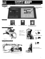
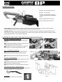
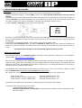
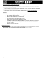
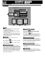
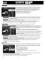
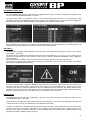
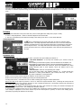
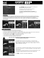
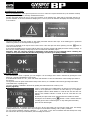
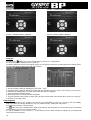
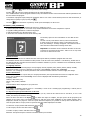
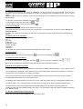
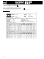
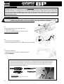
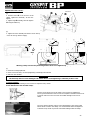
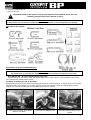
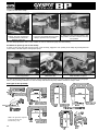
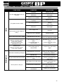
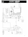
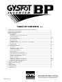
TABLE OF CONTENTS V2.2 1234- PRESENTATION, SAFETY RECOMMENDATIONS AND GENERAL PRECAUTIONS ........................................................ 2 DESCRIPTION OF THE MACHINE........................................................................................................................... 3 INSTALLATION OF THE MACHINE ......................................................................................................................... 5 PRODUCT OPERATION ......................................................................................................................................... 7 Key definition ................................................................................................................................................ 7 Recommendations on the use of welding modes ............................................................................................. 8 Use of C clamp modes ................................................................................................................................... 9-12 Use of X clamp modes ................................................................................................................................... 12-14 Use of the single sided gun ............................................................................................................................ 14 Error management ........................................................................................................................................ 15 Welding spot counter .................................................................................................................................... 16 Recording features (log report – user ID mode – users programs) ................................................................... 16-18 SD memory card ........................................................................................................................................... 19 GYSPOT software .......................................................................................................................................... 19-22 5- PRECAUTIONS and SERVICING ............................................................................................................................. 23 User training ................................................................................................................................................. 23 Preparation of the parts to assemble .............................................................................................................. 23 Single sided gun welding ............................................................................................................................... 23 Use of the under panel arms .......................................................................................................................... 23 Nuts circular joints ........................................................................................................................................ 23 Replacement of the caps and electrodes ......................................................................................................... 23 Level and efficiency of the cooling liquid ......................................................................................................... 23 Cleaning or replacement of the welding tools .................................................................................................. 23 Purging of the pneumatic filter ....................................................................................................................... 23 Generator maintenance ................................................................................................................................. 23 Replacement or adjustment of C clamp arms .................................................................................................. 24-26 Replacement or adjustment of X clamp arms .................................................................................................. 26-27 Replacement or adjustment of QC clamp arms ................................................................................................ 27-28 6 – SYMPTOMS / REASONS / SOLUTIONS .................................................................................................................. 29 7 – DECLARATION OF CONFORMITY ......................................................................................................................... 30 8 - WARRANTY......................................................................................................................................................... 30 9 – CIRCUIT DIAGRAM ............................................................................................................................................. 31 10 - CHARACTERISTICS............................................................................................................................................ 32 11 - PICTOGRAMS .................................................................................................................................................... 32 Autres langues disponibles sur la carte SD. Other languages are available on the SD card. Weitere auf SD-Karte verfügbare Sprachen. 20.08.15–V2.2 Thank you for your choice! Before installing and using the product or before maintenance, please read carefully the following safety recommendations in order to avoid accidents to the users and damage of the welding process. GYS cannot be held responsible for the damages occurring to persons or belongings, following the use of the machine in the following circumstances: - Modification or disabling of safety elements, - Non-respect of the recommendations written in the user manual, - Modification of the characteristics of the product, - Use of accessories other than the GYS accessories , or accessories not adapted to the machine - Non-respect of the regulations and particular dispositions in the country where the machine is installed. 1- PRESENTATION, SAFETY RECOMMENDATIONS AND GENERAL PRECAUTIONS This product has been designed to carry out the following operations in car body workshops: - Spot welding on metal sheets with a pneumatic clamp, - Welding of metal sheets with a single sided gun, - Welding of nails, rivets, washers and studs, - Repair of bumps and impacts (impacts of hail with the option « quick repair”). GENERALITIES 1. The operators must have followed up an appropriate training. 2. The repair and maintenance operations can only be performed by qualified personnel. 3. The operator is responsible for the respect of the car manufacturer’s recommendations, regarding the protection of the car electrical and electronic equipments (car computer, car radio, alarm, air bag, etc…). 4. Before any repair or maintenance operation, the compressed air supply must be disconnected and depressurized. 5. The electrodes, arms, as well as the other secondary conductors can reach a very high temperature and remain hot very long after having stopped the machine. Pay particular attention to the risks of serious burns. 6. It is necessary to make a regular preventive maintenance on the machine. MAINS SUPPLY 1. Check whether the unit is correctly connected to the earth and that the connection to the earth is in good condition. 2. Check whether the workbench is connected to the earth coupler. 3. Make sure that the operator has no contact with the metal parts to be welded without any protection or with wet clothes. 4. Avoid being in contact with the welding part. 5. Do not make any spot welding operations in very wet areas or on a wet floor. 6. Do not weld with worn out cables. Make sure that there is no isolation defect, nor stripped cables nor loose connections, and that there is no cooling liquid leaks. 7. Before performing any control or maintenance operation, switch off and disconnect the unit directly from the plug. EYE AND BODY PROTECTION 1. During the welding process, the operator must protect himself from possible projections of steel in fusion with clothes like : leather gloves, welding aprons, safety shoes, welding helmets or glasses for filtering radiations and projections. Similarly, during grinding or hammering operations, the operator must wear eye protection. 2. The tightening force of the clamp can reach 550 daN. Keep away all body parts from the mobile elements of the clamp to avoid any risk of squeezing, of fingers in particular. 3. Do not wear rings, watches, or jewellery, which are current conductors and can cause serious burns. 4. All the protection boards must be in good condition and maintained in place. Never look at a welding arc without any eye protection. Protect the environment near the product against projections and reflections. FIRE 1. 2. 3. 4. 5. Make sure that the sparks will not cause fire, especially near flammable material. Check that fire extinguishers are near the operator. Use the product in a room with extractor fans Do not weld on combustible or lubricant containers, even empty, nor on containers containing flammable material. Do not weld in an atmosphere charged with flammable gas or fuel fumes. ELECTRO-MAGNETIC COMPATIBILITY Near the spot-welding machine, check whether: - there are no other power supply cable, no control lines, no telephone cables, no radio or TV reception appliances, no watches, no mobile phones, no magnetic cards, no computers nor any other electronic appliance. - there are, in the surroundings, no persons using active medical appliances (pacemakers, acoustic prosthetics). Plan extra protections if other products are to be used in the vicinity of the machine. In order to protect the electronic control units on the vehicles, it is recommended to : - disconnect the battery of the vehicle. - disconnect the airbag control unit. - disconnect, and even remove the electronic control units if they are in the immediate vicinity of the welding area. This product is designed to be used in an industrial or professional environment, as defined in the CISPR11 publication. In a different environment, it might be difficult to ensure electromagnetic compatibility. 2 2 – DESCRIPTION OF THE MACHINE BP Front panel SD card reader Display board for communication with the user BP rear panel Fan with dust-proof filter 32 A D curve circuit breaker Pneumatic filter, connection to the pneumatic network X clamp (for BP.LX or BP.LCX) B button : Remote control for the thickness of the sheet A button : Remote control to choose the metal steel Over-opening of the clamp Close the clamp and weld Arms nuts C clamp (for BP.LC or BP.LCX) C arm Close / Weld Remote control of the thickness of the sheet metal Locking / Unlocking C - Lever 3 QC clamp (for BP.LQC) A button : close the clamp and weld B button : over opening. C button : remote control for type of steel and sheet thickness. Acknowledge button. D lever: blocking lever for the arm. E lever: locking lever for the arm. Over opening : by pressing button B, the over opening of the clamp can be activated. The electrode retracts inside the clamp, leaving an 80mm access to the welding area, instead of the usual 20mm at rest. Opening of the arm : if an opening of more than 80mm is required to access the welding area, simply open the arm and close it down. In order to do this, turn the locking lever E until it locks on the back of the clamp, and then unblock the arm by pushing upwards the lever D (more details on page 28). Assembling the clamp handle, clamp stand and earth cable (accessories bag) Fig. 1 & 2 : X clamps (BP.LX and BP.LCX) Assemble the clamp stand on the right or left side of the machine ①Assemble the clamp handle on the left or right side of the clamp, depending on the preferred choice. ② Depending on the arms used, position the clamp either using the hook or using the clamp handle (see left). - Fig. 1 - - Fig. 2 - - Fig. 3 - - Fig. 4 - Fig. 3 : C clamp (BP.LC and BP.LCX) Assemble the c-clamp stand on the right hand side of the machine using the three M5x12 provided screws. Assemble the handle on the left hand side of the clamp. Fig. 4 & 5 : QC clamp (BP.LQC) Assemble the QC clamp stand using the provided M5 screws (see Fig. 5) Assemble the clamp stand on the left hand side of the machine using the provided M5 screws. Assemble the handle on the left hand side of the clamp. Earth cable ( BP.LX / BP.LC / BP.LQC / BP.LCX) Assemble the copper plate on the extremity of the earth cable This earth cable has to be used with the gun. Air connector Assemble the air connector on the air filter. 4 - Fig. 5 - 3- INSTALLATION OF THE MACHINE Before use - - Several verifications are necessary before using the unit to ensure good performance of the machine : Check the electrical line voltage: it should be 400V, 3 phases, with a 32 A delayed circuit breaker, curve D (or fuse of aM type). Check the cross section of the cable going from the main electrical board to the socket where the machine will be plugged : it should be 4x6 mm2. If this cable is longer than 10m, use a conductor size of 10mm². If you use an electrical extension cord, use a 6mm² conductor size (10mm² if electrical line + extension cord total length is superior to 10m). Connect a 3 phase + earth plug (minimum 32A) on the supply cable. GYSPOT INVERTER BP.LX BP. LC BP.LQC BP. LCX - - Be careful: in order to avoid voltage drops which can generate bad welding spots, you must never have overloaded electrical lines, nor supply cable diameters which cross section are not large enough. Also, the mains plugs must not be too far from the circuit breaker. If the machine is not sufficiently supplied, it is not possible to ensure a good welding quality. Check that the air compressed network can deliver a minimum of 7 bars (dry air), then connect the compressed air network on the back of the machine. The machine must not be used on an air compressed network with a pressure inferior to 3 bars. The machine cannot be used on a air network with a pressure inferior to 3 bars. Filling the cooling tank GYS recommends that you use CORAGARD CS330 (or equivalent) cooling liquid in this cooling tank, for more information, visit the website: http://www.aqua-concept-gmbh.eu The use of other cooling liquids, and in particular standard cooling liquids, can lead to the accumulation of solid substances inside the cooling system (due to electrolysis), this will negatively impact the cooling efficiency, and possibly cause total obstruction of the system. Any degradation to the machine caused by the use of cooling liquids different from the CS330 (or equivalent) will not be considered under warranty. The CORAGARD CS330, used undiluted, provides anti-freeze protection down to -20°C. If it is necessary to dilute the coolant only use distilled water; TAP WATER is NOT RECOMMENDED to dilute CS330! NB: a minimum of 10 litres should be used in the tank to provide minimum protection for the cooling system. 30 litres of pure CS330 20 litres of CS330 + 10 litres of distilled water 10 litres of CS330 + 20 litres of distilled water anti-freeze protection down to -20°C anti-freeze protection down to -13°C anti-freeze protection down to -5°C Any damage to the machine due to the freezing of cooling liquid will not be accepted under warranty. To fill the tank with cooling liquid, proceed as follows: Put the pneumatic clamp on its stand Fill the tank with 30 litres of cooling liquid - this should reach the middle of the min / max indicator on the side of the machine. 5 Safety recommendations regarding CS330 cooling liquid: - In case of contact with the eyes, rinse thoroughly with plenty of water immediately after contact (remove contact lenses first if worn). Seek medical help if necessary. - In case of contact with the skin, wash thoroughly with soap and plenty of water. Remove any contaminated clothing, and if skin irritation occurs (redness etc…) consult doctor. - In case of ingestion, rinse the mouth out thoroughly, and drink plenty of water - consult your doctor immediately. Maintenance: It is recommended that the cooling liquid is changed every 2 years. To empty the coolant tank, proceed as follows: NB: Ensure there is a container available near-by to collect the cooling liquid as it drains. Make sure an arm is fitted on the C-clamp Select the C-clamp adjustment mode in the machine menu. Unscrew the mobile electrode from the clamp. Select the normal mode in the menus. Press the welding button on the clamp to activate the pump. Use the container to collect the liquid as it drains from the clamp. In the absence of welding, the pump will stop automatically after 2 minutes. It will therefore be necessary to press this button several times to completely empty the tank. When the tank is empty, go back to the C-clamp adjustment mode in the menus and re-connect the mobile electrode to the clamp. Fill the tank with the new cooling liquid. Starting the machine Switch ON the circuit breaker. The electronic card starts a test and initialisation cycle of the parameters during a period of about 10 seconds. At the end of this cycle, the machine is ready to be used. When the machine starts to work, liquid circulates in the cables. Check that there are no leaks. 6 4- PRODUCT OPERATION Key definition . ① Key _Pressing the key allow to select the clamp mode, gun mode or clamp adjustment. - Pressing this key 2 seconds allows to come back to normal mode from the other modes. - Pressing this key 2 seconds brings the spot counter to zero, when it is displayed. - Pressing briefly twice this key erases the report that is displayed on the screen, when in the visualisation mode. - Pressing briefly this key when in program saving mode erases the selected program. ② Save a report More details can be found on this function in the corresponding chapter. The « record » key saving of a report. The « visualise » key of spots performed. allows to enable or disable the allows to read the sequence ③ Use of the advanced modes The MODE key allows to navigate through 3 different modes: STANDARD MODE, MULTISHEET MODE, MANUAL MODE. A long press on the MODE key allows to enter the configuration mode, where the language and date can be edited and the sound alarm activated for “current too low” or “low pressure” messages. The up and down keys (in the circle) allow to select the parameter to modify (sheet thickness, type of steel, arm used). The + and – keys allow to modify the parameter. ④ Save user welding parameters The « save » key allows to save user welding parameters (mode, sheet thickness, welding current, welding time or electrode force) The « recall » key allows to call back previously saved welding settings. The machine automatically goes to manual mode, recalling the saved parameters (current, welding time, force) and the tool used (clamp or gun). ⑤ Steel sheet thickness setting This setting allows to select the thickness of the steel sheets to weld. The sheet thickness can be adjusted using the + and – keys (in the circle, position 5). The thickness can be selected amongst the following preset values: 0.6, 0.8, 1.0, 1.2, 1.5, 1.8, 2.0, 2.5, 3.0 mm. ⑥ Type of the steel sheet setting This setting allows to select the type of steel sheet to weld, amongst 4 families: coated steel, HTS steel, UHTS steel, BORON steel. This setting can be adjusted using the + and – keys. ⑦ Arm used setting When a clamp is used (either C or X), the user should specify here the length of the arms fitted on the clamp, so that the machine will adjust automatically the air pressure to get the requested electrode force. 7 Recommendations on the use of welding modes : Only qualified and specially trained personnel are permitted to use of the spot-welder. Please observe repair manuals of respective car- manufacturers before carrying out any welds. The correct application of instructions specified in the user manual and commitment to the indications of the manufacturer as well as the necessary preparations, implementations and tests of welding jobs lies within the responsibility of the user. Several welding modes are available on GYSPOT S7 spot welding machines. The STANDARD, MULTI, and GYSTEEL modes allow programming the machine by entering sheet thickness and type of steel. The MANUAL mode allows programming individually each welding parameter according to the car manufacturer’s specification: welding current, welding time, clamp force. The AUTO, ENERGY, and CAR MANUFACTURER modes are available on GYSPOT S7 models only. The AUTO mode allows welding without entering any parameter inside the machine. This mode may be used on all welding spots identified as non-critical by the car manufacturers. For the welding spots identified as critical by car manufacturers, refer to their repair specification, and use either the MANUAL mode or the CAR MANUFACTURER ´s mode. In the MANUAL mode, the exact welding parameters from the repair specification may be entered. In the CAR Manufacturer’s mode, welding parameters approved and sometimes requested by car manufacturers are saved and can be recalled. In order to safeguard the quality of each welding spot we recommend carrying out 2 sample welds and a pull out test with the same steels and applying the same distance from one another required by the job. The welding spot is acceptable if the pull-off leads to the extraction of the nugget and the tearing of the steel, with a minimum nugget diameter in accordance with the car manufacturer specifications. 8 Using pneumatic clamps When using the pneumatic clamp, always disconnect the copper plate used in single sided gun welding. For the GYSPOT BP.LCX, select the type of clamp to be used with the ! key on the front panel. BP-LCX : to ensure the efficiency of the cooling system, it is essential that both clamps (C and X) are equipped with their respective arms, and that the pipes are properly attached to their respective connectors ATTENTION : The clamps and gun are connected to the same power supply, therefore when one is in use, current will be delivered to all tools. For safety, ensure sure that the clamps and gun are always placed on the trolley when not in use (clamp stand on either side of the trolley, and the gun stand on the arm). Failure to follow this precaution may result in serious damage to the user, the generator and its tools, and there is a high risk of sparks and metal spatter. C clamp and QC clamp ♦ Tighten the C-clamp using the locking lever and check that the screw between the arm and the clamp is correctly tightened. ♦ The clamping force is calculated by the machine, considering the force setting or the thickness of the sheets selected. C clamp adjustment mode : The key is used to enter the clamp adjustment mode. The clamp adjustment mode allows the user to close the clamp and apply the programmed force on the electrodes without any current flowing. This mode is used to adjust the arms. The clamp will remain closed as long as the button remains pressed; this allows the user to check the alignment of the electrodes and positioning of the caps. Press for 2 seconds to revert back to standard mode. For the GYSPOT BP.LQC, systematically select this mode prior to changing the arms in order to stop the cooling liquid pump. The electrode then retracts inside the clamp. The red LED on the acknowledge button switches on indicating that the pump has stopped. STANDARD mode : This is the default mode when the machine starts. Quick and easy spot welding by selection of: - The sheet thickness : it can vary from 0.60mm up to 3.0mm in steps of 0.05mm. When welding 2 metal sheets together, enter the thickness of the thinner one. When welding 3 metal sheets together, enter the total thickness divided by 2. - The type of steel (coated steel, HSS steel, UHSS steel, BORON steel). When welding different types of steel together, select the hardest steel in the assembly. - The arm used : select the corresponding arm number. The up and down button (key definition diagram, (3) ) scrolls through the parameters to modify (sheet thickness, type of steel, arm used). The + and – keys allow modification of each parameter. Button A on the clamp allows the user change the thickness of the sheets to be welded remotely. Button B on the clamp allows the user to spot weld with the selected parameters. Before the weld: If the input air pressure is too low to reach the required electrode force, a warning will sound, and the machine will display the error message “Pressure too low”. Pressing the button for a second time will force the execution of the welding spot with the available air pressure. After the weld: If the welding current measured during the spot is 6% less than the setting, the machine will display the error message “Current too low” - the welding spot should be checked. A message will be displayed at the end of every welding spot, showing the measured welding current and electrode force. This message is displayed on the screen until a key on the control panel is pressed, or until a new welding spot is performed, by pressing the B button on the clamp. 9 MANUAL mode This mode allows the user to manually select the welding parameters, for example when following instructions from a manufacturer. The default settings in manual mode correspond to the settings automatically selected in standard mode (thickness and type of sheet, electrode force, arm). The parameters can be adjusted using the + and – keys (Key Definition diagram, (3) ). The up and down keys allow navigation from one parameter to the next ♦Welding current (2000 to 13000 A, steps of 100 A) displayed in kA. ♦Welding time (100 to 850 ms, steps of 10 ms) ♦Electrode force (100 to 550 daN, steps of 5 daN) ♦Arm used on the clamp (number and length) Before the weld: If the input air pressure is too low to reach the required electrode force, a warning will sound, and the machine will display the error message “Pressure too low”. Pressing the button for a second time will force the execution of the welding spot with the available air pressure. After the weld: If the welding current measured during the spot is 6% less than the setting, the machine will display the error message “Current too low” - the welding spot should be checked. A message will be displayed at the end of every welding spot, showing the measured welding current and electrode force. This message is displayed on the screen until a key on the control panel is pressed, or until a new welding spot is performed, by pressing the B button on the clamp. Press for 2 seconds to revert back to standard mode. Multi-sheet mode This mode allows the user specify the thickness and type of each sheet in an assembly of 2 or 3 sheets. Using The up and down button (key definition diagram, (5) ) allows selection of the parameters for each sheet. When the parameters for a sheet are highlighted, the sheet thickness and type of steel can be adjusted using the + and – keys (key definition diagram, (3) ). The individual sheet parameters that can be adjusted in this mode are : - Sheet thickness : it can vary from 0.60mm up to 3.0mm in steps of 0.05mm. -The type of steel for each sheet : standard steel, HSS steel, UHSS steel, BORON steel. - To activate the required sheet, press the up and down keys (button definition diagram, (3) ) to highlight the required sheet ; then use the + and – keys to select the thickness and type of steel. Before the weld: If the input air pressure is too low to reach the required electrode force, a warning will sound, and the machine will display the error message “Pressure too low”. Pressing the button for a second time will force the execution of the welding spot with the available air pressure. After the weld: If the welding current measured during the spot is 6% less than the setting, the machine will display the error message “Current too low” - the welding spot should be checked. A message will be displayed at the end of every welding spot, showing the measured welding current and electrode force. This message is displayed on the screen until a key on the control panel is pressed, or until a new welding spot is performed, by pressing the B button on the clamp. Press for 2 seconds to revert back to standard mode. GYSTEEL Mode The GYSTEEL mode is optional and is configurable in the setup menu that is activated by pressing the mode key for 2 seconds (auto mode on / off). The GYSTEEL mode is identical to normal mode except that the user enters the yield strength of steel. The Ys may be found using a durometer such as Gysteel Vision Re: 1-10 corresponds to mild steels. Re: 11-18 corresponds to HSS/THSS steels. Re: 19-35 corresponds to UHSS steels. Re: 36-99 corresponds to boron steel. ♦ Sheet thickness: from 0.60mm up to 3.00mm by steps of 0.05mm. ♦ Type of arm used. The up and down button ( or ) scrolls through the parameters to modify (sheet thickness, Yield strength, arm used). The + and – keys allow modification of each parameter. Button A on the clamp allows the thickness of the sheets to be welded to be changed remotely. Button B on the clamp allows the user to spot weld with the selected parameters. 10 CAR MANUFACTURER Mode : The CAR MANUFACTURER mode is optional and is configurable in the setup menu that is activated by pressing the mode key for 2 seconds (CAR MANUFACTURER : ON / OFF). This mode allows calling, in a nominative manner, a pre-recorded welding spot according to a car manufacturer repair specification. Select the CAR MANUFACTURER in the left column, then by pressing the (+) key the spots list is displayed on the right column. Select the requested welding spot (highlighted); the machine is ready to weld. User programmed welding spots can be recalled by selecting USER in the list of car manufacturers. The welding spots can be programmed using the welding spot programming module in the GYSPOT software. AUTO Mode : The AUTO mode is optional and is configurable in the setup menu that is activated by pressing the mode key for 2 seconds (AUTO MODE : ON / OFF). On GYSPOT BP.LC-s7 and BP.LCX-s7 machines, this mode can be used with the C1, C2, C3, C4, C5, C6, C7 and C9 arms. It cannot be used with the C8, C10 and C11 arms, for which the error message « ARM NOT COMPATIBLE » will be displayed if they are selected. On GYSPOT BP.LQC-s7 machines, this mode can be used with the QC1, QC2, QC3, QC4, QC6 and QC7 arms. This mode allows welding steel sheets without specifying any parameter on the screen of the machine. The machine determines the adapted welding parameters. In order to use this mode, a calibration should be first performed by closing the clamp without any steel between the electrodes. Press the « Close clamp / weld » button. The message « Close clamp without steel » appears on the screen. Press the button again to perform the calibration. Once the calibration has been performed, the machine displays all the parameters to zero, and is ready to weld. Close the clamp on the area to weld and weld automatically, without entering any parameter inside the machine. Every 30 welding spots, a new calibration will be requested. ENERGY Mode : The ENERGY mode is optional and is configurable in the setup menu that is activated by pressing the mode key for 2 seconds (ENERGY MODE : ON / OFF). This mode allows controlling the energy transferred during the welding spot. This mode is not designed for the repair, but is rather meant to be used by car manufacturers and independent control labs. In order to use this mode, a calibration should be first performed by closing the clamp without any steel sheets between the electrodes. Press the « Close clamp / weld » button. The message « Close clamp (without steel) » appears on the screen. Press the button again to perform the calibration. Once the calibration has been performed, the machine displays the last parameters selected for welding current and energy. 11 The user can then change the welding current, the energy, and the impedance. The machine will weld during the time necessary to reach the requested energy. If the welding is too long, the machine will display an error message « Timeout (ms) » X clamp ♦ Line up the electrodes so they face each other, then set and tighten the clamp arms (couple: 15 Nm). ♦ Enter « clamp adjustment » mode to check the alignment of the electrodes. ♦ The force is calculated by the machine according to the setting of the force or of the sheet thickness. Clamp adjustment The key is used change from one tool to the next, as well as to enter the clamp adjustment mode. The clamp adjustment mode allows the user to close the clamp and apply the programmed force on the electrodes without any current flowing. This mode is used to adjust the arms. The clamp will remain closed as long as the button remains pressed; this allows the user to check the alignment of the electrodes and positioning of the caps. STANDARD mode This is the default mode when the machine starts. Quick and easy spot welding by selection of : - The sheet thickness : it can vary from 0.60mm up to 3.0mm in steps of 0.05mm. When welding 2 metal sheets together, enter the thickness of the thinner one. When welding 3 metal sheets together, enter the total thickness divided by 2. - The type of steel (coated steel, HSS steel, UHSS steel, BORON steel). When welding different types of steel together, select the hardest steel in the assembly. - The arm used : select the corresponding arm number. The up and down button (key definition diagram, (3) ) scrolls through the parameters to modify (sheet thickness, type of steel, arm used). The + and – keys allow modification of each parameter. Button A on the clamp remotely adjusts the thickness of the sheets to be welded. Button B on the clamp creates a welding spot using the selected parameters. Pressing button close / weld allows the user to make a welding spot using the selected parameters. Before the weld: If the input air pressure is too low to reach the required electrode force, a warning will sound, and the machine will display the error message “Pressure too low”. Pressing the button for a second time will force the execution of the welding spot with the available air pressure. After the weld: If the welding current measured during the spot is 6% less than the setting, the machine will display the error message “Current too low” - the welding spot should be checked. A message will be displayed at the end of every welding spot, showing the measured welding current and electrode force. This message is displayed on the screen until a key on the control panel is pressed, or until a new welding spot is performed, by pressing the B button on the clamp. 12 Multi-sheet mode This mode allows the user specify the thickness and type of each sheet in an assembly of 2 or 3 sheets. The first piece (Thickness of the metal sheet 1) is selected. The up and down button allows the selection of the parameters for each sheet. When the parameters for a sheet are highlighted, the sheet thickness and type of steel can be adjusted using the + and – keys. The parameters to set in that mode are: ♦ Thickness of the metal sheet 1: from 0.60mm up to 3.00mm by steps of 0.05mm. ♦ Type of the metal 1: coated steel, HTS steel, UHTS steel, BORON steel. ♦ Thickness of the metal sheet 2: the same as the metal sheet 1. ♦ Type of the metal 2: the same as the metal sheet 1. ♦ Thickness of the metal sheet 3: deactivate the mode by default (« --- ») or the same as the metal sheet 1. ♦ Type of the metal 3 : deactivate the mode by default (« --- ») or the same as the metal sheet 1. ♦ To activate the metal sheet 3 press the up and down keys to highlight the metal sheet 3. Before the weld: If the input air pressure is too low to reach the required electrode force, a warning will sound, and the machine will display the error message “Pressure too low”. Pressing the button for a second time will force the execution of the welding spot with the available air pressure. After the weld: If the welding current measured during the spot is 6% less than the setting, the machine will display the error message “Current too low” - the welding spot should be checked. A message will be displayed at the end of every welding spot, showing the measured welding current and electrode force. This message is displayed on the screen until a key on the control panel is pressed, or until a new welding spot is performed, by pressing the B button on the clamp. Press for 2 seconds to revert back to standard mode. GYSTEEL mode The auto mode is optional and is configurable in the setup menu that is activated by pressing the mode key for 2 seconds (auto mode on / off). The auto mode is identical to normal mode except that the user enters the yield strength of steel. The Ys may be found using a durometer such as Gysteel Vision Re: Re: Re: Re: 1-10 corresponds to mild steels. 11-18 corresponds to HSS/THSS steels. 19-35 corresponds to UHSS steels. 36-99 corresponds to boron steel. ♦ Sheet thickness: from 0.60mm up to 3.00mm by steps of 0.05mm. ♦ Type of arm used. The up and down button ( or ) scrolls through the parameters to modify (sheet thickness, Yield strength, arm used). The + and – keys allow modification of each parameter. Button A on the clamp allows the user change the thickness of the sheets to be welded remotely. Button B on the clamp allows the user to spot weld with the selected parameters. Press for 2 seconds to revert back to standard mode MANUAL mode This mode allows the user to manually select the welding parameters, for example when following instructions from a manufacturer . The settings proposed by default in the manual mode correspond to the settings automatically selected by the standard mode (thickness and type of sheet, electrode force, arm). The parameters can be adjusted using the + and – keys. The up and down keys scroll from one parameter to the next: ♦Welding current (2000 to 13000 A, steps of 100 A) displayed in kA. ♦Welding time (100 to 850 ms, steps of 10 ms) ♦Electrode force (100 to 550 daN, steps of 5 daN) ♦Arm used on the clamp (number and length) Before the weld: If the input air pressure is too low to reach the required electrode force, a warning will sound, and the machine will display the error message “Pressure too low”. Pressing the button for a second time will force the execution of the welding spot with the available air pressure. After the weld: If the welding current measured during the spot is 6% less than the setting, the machine will display the error message “Current too low” - the welding spot should be checked. A message will be displayed at the end of every welding spot, showing the measured welding current and electrode force. This message is displayed on the screen until a key on the control panel is pressed, or until a new welding spot is performed, by pressing the B button on the clamp. Press for 2 seconds to revert back to standard mode. 13 SETTINGS MODE : The SETTINGS mode can be accessed by pressing the MODE key during more than 2 seconds. The language of the menus can be selected on line 1. The date and time can be entered on line 2. The GYSTEEL, CAR MANUFACTURER, AUTO, ENERGY, STANDARD and MULTITOLE modes can be also be disabled in this menu. GLUE MODE : In the SETTINGS menu shown above, a specific mode can be selected in case there is glue in between the steel sheets to be welded. In this case, a GLUE mode can be switched ON or OFF in this menu. If the GLUE mode is activated, a pre-spot is performed prior to the welding spot. The duration of this pre-spot is selected in milliseconds, from 0 to 400ms, by increments of 50ms. When this mode is selected, the text « GLUE » appears in the welding modes STANDARD, MANUAL, MULTI, GYSTEEL. Using a single-sided gun ♦ Connect the copper plate onto the generator's earth cable. ♦ Firmly fix the earth plate as near as possible to the welding area. In case of spot welding with the single sided gun, always fix the earth plate to the sheet that will not come into contact with the welding electrode (so that the welding current will flow through the 2 sheets to be welded). ♦ Select the GUN tool using the key, or by pressing the gun trigger. ♦ The standard mode with 'star welding' is launched by default. ♦ The gun can be used in both standard and manual modes. - ! Never leave the inertia hammer on the gun when it is hung from the balancer as this may damage the welding cables. ♦ In standard mode, the gun can weld a maximum of 1.5mm thick sheets. When using the gun, the operator can choose between several tools (single spot, carbon shrinking, star welding, studs, rivets, washers, stitches). The tool selection is made with + and – keys. ♦ In manual mode, the maximum permitted welding current is 9 kA during a period that will not exceed 600 ms, it is therefore impossible to select higher values for these parameters. Set the generator by selecting the thickness of the sheet metal with the key + and -. It is possible to modify the parameters time and current in manual mode. Press 14 for 2 seconds to revert back to standard mode. When highlighted, a parameter can be adjusted using the + and – keys. The parameter to the next. and keys allow movement from one ATTENTION : The clamps and gun are connected to the same power supply, therefore when one is in use, current will be delivered to all tools. For safety, ensure sure that the clamps and gun are always placed on the trolley when not in use (clamp stand on either side of the trolley, and the gun stand on the arm). Failure to follow this precaution may result in serious damage to the user, the generator and its tools, and there is a high risk of sparks and metal spatter. Error management Different events might cause the appearance of error messages. They can be classified in three categories: ♦ General Warnings: i.e overheating, lack of electrode force or welding current, etc… These messages appear on the screen, and remain until a key is pressed. ♦ Installation Errors (air pressure, electrical power supply). ♦ Major Faults: These defects cause the display of an error message that locks the machine ♦ The thermal protection relies on a thermostat located on the diode bridge, this feature will lock the machine, and display the message “overheating” Low battery (clock) : The message « Low battery (clock) » appears after switch ON of the machine and alerts the user that the voltage of the battery on the command board is too low. This battery ensures the saving of the date and time when switching OFF the machine. Tool out of order : The message « Tool out of order » appears after switch ON of the machine and alerts the user that a button or trigger is constantly pressed, or a permanent short-circuit is detected. Control the trigger of the gun, as well as the buttons on the clamps in order to make this message disappear. Current too low : If the welding current measured during the spot is 6% less than the setting, the machine will display the error message “Current too low” - the welding spot should be checked. A message will be displayed at the end of every welding spot, showing the measured welding current. This message is displayed on the screen until a key on the control panel is pressed, or until a new welding spot is performed, by pressing the B button on the clamp. If the machine cannot deliver the requested current, then the following message appears. The welding spot is not performed, and the message must be acknowledged to perform a welding spot. 15 Insufficient air pressure : Before the welding spot: If the input air pressure is too low to reach the required electrode force, the machine will beep and display the following error message “Insufficient Pressure”. Pressing the button allows the user to force the execution of the welding spot, which will be performed with the air pressure available. If the actual measured clamping force is too low, then the machine will display the following message “Low Pressure”. Welding spot counter The spot counter will count the number of spot welds performed with the same caps. If the welding spot is performed without any problem, the message below left, appears. The counter is displayed on the top left corner of the screen. After the caps have been replaced, press the button to reset the counter to zero. If more than 200 welding spots are done with the same caps, then the machine will display the below warning message. In this case, the warning message “Change tips” is also recorded in the traceability report.. Attention: After the warning message is displayed, if the nozzles are not changed before resetting the counter to zero, the nozzles may become badly damage and cause poor quality welding. Recording features The "Identification" mode is optional; you can configure it in the settings menu which is activated by pushing the mode button for 2 seconds (identification mode on/off). If the identification mode is « off », enter a file name and activate it to store the information of the welding spots made in the memory. The log book stores the spots made with the clamp in the memory. It is available in all modes by pressing both buttons located bellow the “reporting” icon. The user’s program is available in all modes by pushing the buttons bellow the “memory” icon. Report (log book) Saving a report allows spot welding data to be stored on a memory card, in order to use it again later or retrieve it at a later date eg. on a computer. GYS supplies software called GYSPOT to read the SD card and the user manual. This GYSPOT software is stored in the SD card with the user manual. By default, the report mode is not activated when the machine is started. Pressing the record button (on/off) and the « mode » button starts the recording process in the selected log file. To stop saving the information, press the save button again. The new report has: an identifier entered by the user, all the spots made, the arm and the clamp used, the settings (voltage and pressure). It puts also stores any messages received whilst recording: LOW I, LOW P, CAPS PB. You can enter the identifier using the 4 buttons: +, -, up or down. If you enter an identifier that has already been used, the unit will save the new spot information, without erasing the old ones. 16 The View button allows the user to retrieve a previously saved report and view it on the screen. To view a report, stop any current recording by pressing . Use the « mode » button to exit the report displayed. To erase the content of a report , it has to be displayed To erase the report shown, press on screen by pressing "view" and the following message will be on the screen: . When the warning image is displayed, press again and the report content will be erased. The warning image will disappear after 3 seconds. User identification mode: If the identification mode setting is « ON », all the fields of the repair order must be completed or the machine will display « identification defect ». To activate or deactivate the identification mode, an "Identification" SD card must be inserted in the BP drive instead of the "Program" SD card. The setting screen below is activated by pressing the mode button for 2 seconds. When the "Identification" SD card is inserted and the identification mode is « ON », the following screen is displayed This screen allows the selection of default fields « registration number, car brand, car model, chassis number » To exit the screen, press and hold the mode button for 2 seconds. Then, re-insert the '"Program" SD card into the BP drive. Entry of repair order (screen guide): To modify or erase a repair order that has already been created, you will need to use the GYSPOT software on a PC (you are unable to do this on the machine). You can create maximum 100 repair orders. Screen: « Job number » Screen: “User identification” The « left » and « right » arrow keys move the cursor within the field. The up and down arrow keys scroll through letters or figures. Press Esc to erase the field. The Mode button changes the field to modify playback. 17 Screen: « Registration number » (optional) Screen: « Vehicle make » (optional) Screen: « Vehicle model » (optional) Screen: Chassis number (optional) Catalogue The View button , allows you to view all repair orders on the screen - "CATALOGUE": The number of pages is displayed (max 13) at the top The left and right arrow keys scroll through the pages. The up and down arrow keys scroll through the list of Repair Orders. Press the Mode button to display the repair order selected. Use the « mode » button to exit the report view. ♦ The SD card driver allows the management of SD cards > 2 Gb. ♦ Each repair order is linked an archive file xxx.dat.(with xxx=identifier from 001 to 100). In each archive, you can save up to maximum 500 welding points. The repair order names and users are displayed. ♦ The page number is indicated top left. ♦ All the repair orders are saved in the file catalog.GYS. ♦ This file contains the total number of repair orders, the name of each repair order and the name of each user. There are a maximum of 100 repair orders. User programs The 'save' option allows a user program to be entered to save information for future use. 20 memory slots are available; each one contains the following parameters: tool, arm, welding intensity, welding time and pressure. A program can be linked to a clamp and gun. button will save the settings in the manual mode (intensity, time and pressure). The 20 memory slots are indicated The by their identifier (when in use) or by the symbol « --- ». To enter an identifier, use the 4 buttons +,-, up and down arrow keys. When entering an existing user, the machine will erase the previous parameters. 18 The « recall » button allows access to previously saved settings. Pressing will erase the selected program from the saved program list. The « mode » button exits the program selection mode, the machine will then enter manual mode with the parameters and the tool saved in the program. To deactivate a program simply change the parameter value in one of the 3 modes manual, normal or multi metal sheet, or change the tool (clamp or gun) by using the The view . button will retrieve a previously saved report and display it on the screen. SD memory card (ref 050914) This card is a link between the GYSPOT BP and a PC to enable the user to: ♦ Retrieve and print reports for a record of work, and documentation for insurance companies if required. ♦ Upgrade welding parameters or add new languages. ♦ Edit the parameters is in the SD memory card. ♦ Access the user manual stored on the SD memory card. The memory space can store information on more than 65 000 spots. The unit can only work without memory card in manual mode. In other modes, if the memory card is not inserted in the card drive, the following message will appear: The machine must be shut-down and restarted after inserting an SD card”. Important: The machine must be switched off before an SD card is inserted or removed from the reader - failure to do so may result in the loss of data from the card. GYSPOT Software The software allows the user to edit and save the weld reports made by a GYSPOT equipped with a SD drive. The GYSPOT software can be installed from files present on the SD card. In the \GYSPOT V X.XX directory, double click on the INSTALL.EXE file, and follow the instructions to install the software on your PC. A GYSPOT icon is automatically created on the desktop of your PC. 1/ Language selection The software contains several languages: French, English, German, Spanish, Dutch, Danish, Finnish, Italian, Swedish, Russian and Turkish. To choose a language, in the menu, select Options, and then click Languages. Attention: once a language is selected, shut down and re-start the GYSPOT software in order to apply the change. 2/ User identification In order to personalise the reports with your company information, the required fields will need to be completed. In the menu, click on Options and select Identity. A new screen is displayed with the following information: Company name Address / Post code / City Phone / Fax / Email / Website Logo This information will be displayed on your print-outs. 3/ Traceability As a default, the GYSPOT software opens in « Traceability » mode. In the « Welding spot programming » module, click on «Traceability» in the « Options » menu. 3.1/ Import the spot reports made from an SD card To import the spot reports made with your GYSPOT to your PC, insert the SD card into the PC card drive, or use a card reader, and start up the GYSPOT software. Select the drive and click on the Import icon. When the import is complete, the spot reports will be grouped by the identifier of the repair order. The identifier matches up with the report name established on the welding machine, and is displayed in the tab «In progress». Once the reports have been imported, it is possible to search, edit or archive them. To view the spots made in a report, select a report and the spots will be displayed in the table. To search for a report, fill the field and click on the icon To edit a report, select it and click on the icon To archive a report, select it and click on the icon Attention! The imported reports cannot be cancelled until they are archived. 19 3.2/ Consult archived spot reports To consult the report archives, click on the tab “Archives”. The files are grouped by year and month. To view the spot information, select a report and they will appear in the table. For archived reports, it is possible to search, edit or to erase a report. Attention! When a report is archived or erased, the SD card must then be formatted to prevent the report from being imported again. To search for a report, fill the field and click on the icon To edit a report, select it and click on the icon To erase a report, select a report and click on the icon . 3.3/ Purge the SD card. A purge operation will erase all the reports saved on the SD card. To purge and SD card, insert the SD card into your PC card drive or a card reader and, in the menu, click on Options and Purge the SD card . Attention : any reports stored on the SD card that have not already been imported, will be imported automatically before purging. 3.4/ Entering the report information Each report can include the following information: User Car model Repair order Registration number Put into circulation Intervention Comments To enter this data, select a report and enter the information in the report header. 3.5/ Print a report To print a report, select the one required and click . A print preview is displayed. Click . 3.6/ Export the report as a PDF file To export the report as a PDF, select a file, and click on . A preview of the print is displayed. Click . Below shows an example of the parameters saved and printed by using the GYSPOT software. 4/ Welding spot programming module In order to enter the « Welding spot programming » mode, click on « Welding spot programming » in the « Options » menu. The « Welding spot programming » mode allows the user to select welding spots defined by Car Manufacturers. This mode also allows the user to program his own welding spot profiles. Insert the SD card delivered with your GYSPOT spot welding machine in the SD card reader of your PC, then select the corresponding reader identifier in the « Unit Choice» menu. The GYSPOT spot welding machines can accept up to 16 files, which can contain each up to 48 programmed welding spots. The first file called « User » cannot be deleted. It enables the user to add, edit or delete a programmed welding spot. The other files are restricted to Car Manufacturer defined welding spots. It is possible to import downloaded Car manufacturer files from the GYS website (http://www.gys.fr). It is not possible to add, edit or delete a welding spot saved in a Car Manufacturer file. 4.1/ Import a Car Manufacturer welding spot file Double click in the first column and highlight a car manufacturer name. 20 Then, double click in the second column to select a Car Manufacturer file previously downloaded from our website. The list of welding spots defined by the Car Manufacturer are displayed in the second table below. Select a programmed welding spot in order to display the welding spot profile on the screen. 4.2/ Add a programmed welding spot in the USER file In order to add a welding spot in the USER file, select the USER file in the list of files and then click on the button the right of the table below. Enter the name of the welding spot, and then press the TAB key or click outside the list programmed welding spots in order to program the welding parameters. on To program a welding spot, it is possible to select : The prespot tightening duration The preheating current and duration The parameters of the pulses (up to 4 maximum), with pulse ramp-up time, current and duration. Inter pulse parameters can also be selected. The current and duration of the forgeing stages (hot and cold) can also be selected. In order to modify the parameters, click on the buttons When the user changes a parameter, the chronogram of the welding spot profile is updated. To validate the programmed welding spot, click on the button To cancel a programmed welding spot, click the button . . 4.3/ Edit a welding spot programmed in the USER file In order to edit the parameters of a programmed welding spot, select a welding spot in the list and then edit the welding parameters. To validated the modifications, click on the button . 21 To cancel the modifications, click on the button . 4.4/ Delete a welding spot programmed in the USER file Select a welding spot programmed in the list, then click on the button Example of report : 22 on the right of the list. 5- USE AND MAINTENANCE PRECAUTIONS User training Any operator of this machine should receive training adapted to its use in order to gain maximum performance from the unit (e.g.: car body repair training). Adjust the balancer’s spring tension Adjust the balancer’s spring tension with the Allen key equipped. Do not leave the clamp hanging for a long time on the balancer, as it would induce early wear out of this part. Do not let the clamp fall down repeatedly without holding it, as it could damage the balancer. Preparation of the work-piece: Grind and clean the work-piece thoroughly before welding. If protection is being used, ensure that the parts are conducting by testing a sample. Single sided gun welding Before repairing a car, check that the car manufacturer authorizes that welding process. Cooling liquid level and efficiency The cooling liquid level is important to ensure the unit functions correctly. The liquid level should always be between the minimum and maximum levels indicated on the tank. Check the level and efficiency of the cooling liquid regularly, replace if needed. It is recommended replacing the cooling liquid every 2 years. Cleaning the pneumatic filter Ensure the dehumidifier filter located at the back of the machine is cleaned regularly. Generator maintenance The maintenance and repair of the generator should only be carried out by a GYS technician. Any repair/maintenance made to the generator by unauthorized personnel will invalidate the machine's warranty - GYS will not take responsibility for any incident or accident under these circumstances. Cleaning / replacement of welding tools and other items All welding tools are consumable and will deteriorate during use. To extend the lifespan and efficiency of the tools, ensure that they are inspected and cleaned regularly. When using with the Pneumatic Clamp, check that the condition of the electrodes/CAPS (flats, rounded or beveled) is good. If the condition is poor, clean with fine grain sandpaper, or replace (see reference on the machine). When using with the gun, check the condition of the tools: star, single-point electrode, carbon electrode. Clean, or replace if necessary. Ensure the pneumatic filter is clean to prevent the machine overheating. Replacement of the caps/electrodes: ♦ To ensure an efficient welding point, you need to replace the caps every 200 spots - remove the caps using the spanner. (Ref. 050846) ♦ Use grease (ref: 050440) when replacing caps ♦ Caps type A (ref: 049987) ♦ Caps type F (ref: 049970) ♦ Caps beveled (ref: 049994) Caution: The caps must be perfectly aligned. To check the electrode line, see change of arms on pages 18 and 19. 23 Replacement of the arms : ATTENTION : The clamps and gun are connected to the same power supply, therefore when one is in use, current will be delivered to all tools. For safety, ensure sure that the clamps and gun are always placed on the trolley when not in use (clamp stand on either side of the trolley, and the gun stand on the arm). Failure to follow this precaution may result in serious damage to the user, the generator and its tools, and there is a high risk of sparks and metal spatter. Replacement of the C arms : ! Please read the following instructions carefully. Incorrectly tightening or setting the C clamp arms can lead to the arm and clamp overheating and causing damage. Damage caused by incorrect assembly are not covered under the warranty. Ⓐ ♦Switch off the machine, or put the machine into « clamp setting » mode. ♦ Unscrew screw which holds the arm to the clamp. Leave it on the arm to not lose it 60° Ⓑ ♦ Disconnect the cooling liquid pipes. ♦ Unscrew screw and loosen the lever on the side of the clamp. Ⓒ ♦ Remove the clamp arm. ♦ Lubricate both a new arm and the support with contact grease (ref.050440). Specific Installation for C2 and C8 arms For these arms, the electrodes will also need to be changed. Unscrew the short electrode with a flat spanner and remove the injector. Centre the injector along the axle of the clamp (Caution: beveled side outside) and insert it manually (1). Position the long electrode in front and screw it on to the clamp axle (maximum torque 15Nm) (2) Long electrode Short electrode Electrode types: Short: C1, C3, C4, C5, C6, C7, C9, C10 Long: C2, C8 24 Long injector ① Short injector ② Adjustment of the C arms : Ⓓ ♦ Position screw to fix the arm on the clamp. Tighten it in manually - do not overtighten. ♦ Tighten ring manually, then the tighten using the Allen key. Serrer Ⓔ ♦ Tighten the lever manually and check it is not end up against the joint stop (see diagram below). If it is the case go back to stepⒹ. max i OK NO Warning: Clamp and arm may be damaged if the lever is not tightened properly. Ⓕ ♦ Check the cooling liquid level. ♦ Check screws and lever, incorrectly tightening can damage the material. ♦ Switch on the machine. ATTENTION : The warranty does not cover damages and defects due to a bad tightening or assembly of the C arms. C clamp overhaul : The tightening of the following screws need to be inspected every month: Screw between the arm and the clamp: These 4 screws fix the arm to the clamp. They need to be tightened to ensure good transmission of the current. A loose/bad connection leads to loss of current and even worse can cause irreversible damage to the arm or clamp. The screw shown opposite ensures secure attachment of the copper cable which carries current to the clamp. It is recommended that screw tightness is checked every month to prevent irreversible damage inside the clamp. 25 Arms types for the C clamp: Spot control Consumables Spotter consumable box Spanner for cap removal Contact Grease Replacement of the X arms : follow carefully the instructions below. ♦ Turn the machine off, or place machine in « clamp setting » mode. ♦ Place the clamp somewhere above the level of the cooling liquid tank to drain water from the arms. ♦ Wait at least one minute to lower the pressure in the arms. ♦ Unscrew the tightening screws of the circular arm joints. ♦ Remove the arms and drain any excess liquid from the arms. ♦ Put contact grease around the end of the replacement arms that will be connected to the clamp (ref 050440). ♦ Check the condition of the toric joint (toric joint D=25, thickness = 4). ♦ Put the arms on the joint stop, set the alignment so that the electrodes are face to face, then tighten the 2 screws of the circular joint (couple 15 Nm). 26 ♦ Check the cooling liquid level. ♦ Switch on the unit. ! ATTENTION: If the circular joints are not securely tightened as the liquid circulates, the arms could be ejected and cause severe damage or injury. ATTENTION : The warranty does not cover defects or damage caused by incorrect assembly or incorrect tightening of the X-Clamp. Arm types for the X clamp: Replacement of QC arms (GYSPOT BP.LQC) : ATTENTION : The warranty does not cover defects or damages caused by incorrect assembly of the QC arms on the clamp. - VERY IMPORTANT : do not use copper grease on QC arms. - keep the base of the arm and the clamp arm support always clean in order to favour a good circulation of the welding current between the metallic parts in contact. Procedure to change a QC arm on the clamp : When changing a QC arm on the clamp, the cooling liquid pump must always be stopped. To stop the pump, use the clamp adjustment mode on the machine (cf. p.9 of this manual); the red LED on button C lights up indicating that the pump is stopped. The electrode retracts inside the clamp allowing the arm to be removed. 1. Turn lever E to the back of the clamp and place it vertically. 2. Lift lever D to unblock the arm. 3. Move the arm towards the back of the clamp and lift it out of the arm support. 27 To place an arm on the clamp : 1. Insert the arm inside the arm support. The lever E must be in vertical position to allow the insertion of the arm. 2. Turn lever E towards the front of the clamp to push the arm in position. 3. When lever E is pushed forward to the stop position, the arm is inserted correctly into position. Exit the clamp adjustment mode on the machine in order to activate the pump and start welding. Procedure to open a QC arm on the clamp : In order to open a QC arm and get more access on the car body, trigger the over opening of the clamp by pressing button B on the clamp : this will stop the cooling liquid pump. 1. Turn lever E towards the back of the clamp to the stop position. 2. Lift lever D in order to unblock the arm. 3. Move the arm towards the back of the clamp and lift it to open it. To close the arm back down, place it back on the arm support and use lever E to push it back to its position (see paragraph above). Then pressing on button A to close the clamp will activate the pump and the machine is ready to weld. Arm types for the QC clamp : Note : the QC6 arm requires a long electrode (see instructions p.24) 28 6-SYMPTOMS / REASONS / SOLUTIONS SYMPTOMS REASONS The Spot weld doesn’t hold / is not good The caps used are worn out/faulty Insufficient preparation of the work-piece Sand and clean the metal sheet again The arm selected doesn’t match the one installed Check the arm with the software The caps used are worn out/faulty Replace the caps Not enough pressure Check the compressed air network (min. 7 bar) Insufficient preparation of the work-piece Sand and clean the metal sheet again Power supply issue Check the stability of voltage delivered Caps worn out or damaged Change the caps Lack of power only at the C clamp Bad tightening of the arm Please follow the instruction in the C arm adjustment chapter GYSPOT BP.LCX Machine overheats quickly. Power cable expands. Excessive pressure when changing the X arm. C arm missing on the the C clamp. C arm cooling pipes are disconnected Assemble the C arm on the C clamp. Connect the C arm cooling pipes GYSPOT BP.LC Machine overheats quickly. Power cable expands. C arm cooling pipes are disconnected Connect the C arm cooling pipes Clamp The spotter cuts the metal Lack of power at the clamps (C and X) Bad tightening of the chuck Abnormal overheating of the gun Welding Gun Gun liner out The spot weld made doesn’t hold Bad positioning of the earth clamp Bad contact of the earth clamp Lack of power in the gun Loose chuck or accessories Worn out / Damaged consumables SOLUTIONS Replace the caps Check the tightening of the chuck, the star support chuck, and the liner condition. Put back the liner to have the air cool going to the gun Check the earth clamp is securely connected to the metal sheet Check the earth clamp is securely connected to the metal sheet Check the tightening of the chuck and accessories, and the condition of the liner Replace the consumables 29 7 – DECLARATION OF CONFORMITY GYS confirm that the product described within this manual conforms to the following directives: - Low Voltage Directive 2006/95/CE in respect of the harmonized norm EN 62135-1 - Electromagnetic Compatibility Directive EMC 2004/108/CE in respect of the harmonized norm EN62135-2 - Machine Directive 2006/42/EC in respect of the harmonized norm EN 60204-1 - Electromagnetic Field - exposure of workers Directive 2004/40/CE of the 29thof April 2004 in respect of the harmonized norm EN 50445 of 2008. 8 - WARRANTY 1) The warranty is valid for one year only when the certificate of warranty has been filled correctly by the seller. 2) The warranty covers every default or manufacture vice for one year, as from the purchase date (spare parts and labourforce). 3) THE WARRANTY DOESN’T COVER THE VOLTAGE ERRORS, if you don’t use CORAGARD CS 330 or an equivalent liquid, damage due to a bad use, dropped product, dismantling or any more issue due to the carriage. 4) The warranty doesn’t cover any issue due to a maintenance of the clamp or the generator. 5) The warranty doesn’t cover the normal wear and tear of the spare parts (e.g.: cables, clamps, etc.). In case of breakdown, please return the unit to the GYS factory GYS with: - the following certificate of warranty validate by the seller and an explicative note of the breakdown. After the warranty, our After-sales service provides the repairs by acceptance of the quotation. ATTENTION We remind you that we do not accept any product return with carriage cost not included. SOCIETE GYS « S.A.V » : 134 Bd des Loges - BP 4159 53941 SAINT-BERTHEVIN cedex FAX S.A.V : 02 43 01 23 75 Seller stamp: CERTIFICATE OF WARRANTY Reference of the unit: ............................. Purchase date: ....................................... Seller Name Company: ........................... Valid for one year as from the purchase date 30 9 – CIRCUIT DIAGRAM 31 10 - TECHNICAL SPECIFICATIONS ELECTRICAL CHARACTERISTICS Nominal input voltage : U1N Permanent input current : I1N Power at 50 % duty cycle : S50 Permanent input power : Sp Maximum welding input power : Smax Secondary voltage : U2d Maximum short-circuit output current : I2cc Maximum permanent output current : I2P Maximum regulated welding current Circuit breaker Duty cycle THERMAL CHARACTERISTICS Ambient temperature range Transport and storage temperature range Thermal protection by thermistor on the diode bridge MECHANICAL CHARACTERISTICS Protection rating Width Depth Height Weight BP.LX Weight BP.LC Weight BP.LQC Weight BP.LCX OTHER CHARACTERISTICS Maximum air pressure P1 Liquid flow rate Minimum regulated force : F min Maximum regulated force with C clamp : F max Maximum regulated force with X clamp and 440 mm arms Maximum regulated force with X clamp and 120 mm arms 3~400V - 50/60Hz 32 13 kVA 9 kVA 120 kVA 16 VDC 13 000 A 1 300 A 12 000 A 32 A – D curve 1% +5°C +45°C -20°C +70°C 70 °C IP21 65 cm 80 cm 205 cm 160 kg 160 kg 161 kg 180 kg 8 bars 2l / min 100 daN 550 daN 130 daN 550 daN 11 - ICONS V A 3~ U 1n Sp S max U 20 I 2 cc IP 21 Volts Amps Three-phase power supply Nominal input voltage Permanent input power Maximum welding input power Alternating current defined unload Secondary current on short-circuit Protected against rain and moisture. No access to dangerous parts. Caution! Read the user manual before use Separate collection required – Do not throw in a domestic waste bin. Do not use in the open air. Do not use the product in damp/wet environments. IP21. Risk of interference and disturbance of electronic medical devices (i.e. pace-makers) when near of the product. Caution! Strong magnetic field. People wearing active or passive implants must be informed. Always wear suitable protective clothing to shield eyes, hands, and skin, when welding. 32