1
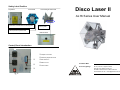
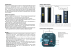
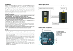
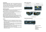
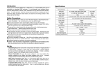
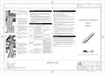
Introduction Cleaning Thank you for selecting Disco II. Disco II is a four-channel DMX laser which can be controlled via a standard DMX controller. It is a lightweight, mini intelligent fixture and is an ideal product for discos, small clubs, exhibitions and any place that need visionary effect. Disco-II provides 50 preset patterns and three operating modes. For safe operation, read this manual before powering or installing the fixture, follow the safety precautions listed below, and observe all warnings printed in this manual and on the fixture. Use a soft cloth and normal glass cleaner to clean the outside casing and the hexagonal reflection mirror. Cleaning frequency depends on the environment in which the fixture operates. Be sure to dry all parts before plugging the unit back in. Specifications Product Name Disco II Model No. AL16-5R/ 30R/ 50R/ 100R/ 200R AL16-05G/ 20G/ 30G Safety Precautions Laser Diode 4.9/ 30/ 50/ 100/ 200mW 4.9/ 20/ 30mW Do not spill liquids in to or on to your unit. If this ever happens, disconnect the main power immediately. Do not connect this unit to any dimmer pack. Always disconnect from main power before making any type of connection. Be sure to locate this unit in a place with adequate ventilation at least 15 cm from a wall, and mount this unit in safe and stable matter. To prevent fire or shock hazard, do not expose this unit to a high temperature or high humidity area. Please unplug unit when not in use. Always keep combustible materials away from the fixture. This unit is intended for indoor use. Use of this unit outdoors voids all warranties. Always refer service to a qualified technician. Never look directly into laser beam. Occasional breaks are necessary to prevent breakdowns. Caution - Use of controls or adjustments or performance of procedures other than as specified herein may result in hazardous radiation exposure! Laser Color Red Green Set Up Unpacking Disco II comes with: 1 hanging bracket, 2 clamp levers, 2 washers, 1 adapter and 1 user guide. Unpack carefully and be sure that no damage has occurred during shipping. If there is anything missing or appear to be damaged please contact your dealer. Power Connection Be sure the source voltage in your area matches the required voltage for your Disco II before plugging your unit in. Incorrect voltage selection will detrimentally affect the operation of this product. DMX Cable Connection Disco II is a four-channel DMX fixture that can be operated with universal DMX controller. This unit and DMX controller require a standard 3-pin XLR connector for data input and data output. Installation/Mounting Disco II should be properly mounted by using a suitable hanging clamp and safety cable. Use in a well-ventilated area. Be sure no ventilation slots are blocked. Model No. Laser Diode 5R5G 20R10G 50R20G 100R30G 200R50G 4.9mW x 20mW + 50mW + 100mW + 200mW + 2 10mW 20mW 30mW 50mW Laser Color Red, Green and Yellow Net Weight 4.5Kgs Power UL Adapter (Input 120V 60Hz & Output DC 12V) or CE Adapter (Input 220-240V 50Hz & Output DC 12V) Classification 4.9~20mW: 3R/ 30~200mW: 3B Size (mm) L300 x W290 x H307 Housing Metal Beam Divergence < 1.5 mrad Operating Temperature 18~25°C Operating Modes (Cont.) Operating Modes (Cont.) DMX Signal Levels Channel 1 Range 0-255 Patterns Selection 221-255 Automatically change all the patterns every 10 seconds 204-220 Sound Active Modes 200-203 : : : 12-15 8-11 4-7 0-3 Pattern50 : : : Pattern3 Pattern2 Pattern1 OFF Channel 3 Channel 2 Range 0-255 Colors and Lines Selection 233-255 Automatically change all the colors and lines every 5 seconds 209-232 Automatically change all the colors and lines every 3 seconds 196-208 Red + Green + Yellow, line2 183-195 Red + Green + Yellow, line1 170-182 Red + Green + Yellow, dotted line 157-169 Green + Yellow, line2 144-156 Red + Yellow, line2 131-143 Red + Green, line2 118-130 Yellow, dotted line2 105-117 Green, dotted line2 92-104 Red, dotted line2 79-91 Red + Green, line 66-78 Yellow, dotted line1 53-65 Green, dotted line1 40-52 Red, dotted line1 27-39 Yellow, line 14-26 Green, line 1-13 Red, line 0 OFF Range 0-255 Mirror Position and Movement Selection 228-255 Sound Active 216-227 Counter Clockwise Channel 4 Channel 4 is functional only when the value of channel 3 is between 0-200 Range 0-255 Mirror Rotation Selection 255 1440° rotation 213-215 Stop 201-212 Clockwise rotation 0-200 360° position changing 1080° 720° 360° 0° 360° 720° 1080° 56 0-55 1440° Not Used Trouble Shooting Operating Modes 1. Stand-Alone Operation (Auto, Sound Active Mode) Auto mode The unit runs built-in program to change the laser effects automatically. Set DIP switch pin 10 to ON, other pins to OFF to run Auto mode Sound Active mode This unit has built-in program that will react to sound and music under Sound Active mode. Set all DIP switch pins to OFF to run Sound Active mode. Please adjust “Sensitivity Adjustment Knob” to fine-tune the optimum level of sound reaction. If there is no light from the unit, please check the main power supply and fuse. If unit does not respond to DMX, please check the DMX cables are connected properly and are wired correctly. If unit does not response to the music please check the sound-activation adjustment. If problems cannot be solved please contact your dealer for service You can adjust the position of green and red light by follow steps to make the best yellow light effect Step1: Set the DIP Switch 12 to ON, others to OFF. (Adjust Mode) Step2: Open the cover at bottom. (Caution! Before you open the cover please project light on to the wall. Never look into beam directly) Knob1: Control the green circle light horizontally. Knob2: Control the green circle light vertically. Step3: Control these 2 knobs to overlap the 2 circles R G 2. Master-Slave Operation (Auto, Sound Active Mode) This mode allows user to link up to 32 units to run the Master-Slave operation. In the Master-Slave operation one unit will act as the controlling unit and the others will react to the controlling unit. Daisy chain your units via the standard XLR microphone cables in the following configuration: ‘Out’ from the first unit to ‘In’ on the second, ‘Out’ from the second to ‘In’ on the third and so on. Auto mode To set the master: Set DIP switch pin 10 and 11 to ON, other pins to OFF. To set the slaves: Set pin 1 to ON, other pins to OFF Sound Active mode To set the master: Set DIP switch pin 11 to ON, other pins to OFF. To set the slaves: Set pin 1 to ON, other pins to OFF 3. DMX Operation DMX operation gives the users freedom to create their own programs tailored to their own individual needs. To run this unit in DMX mode, connect the unit to any standard DMX controller via XLR connectors. Please consult DMX controller manual to determine address. Function Selection Chart DIP SWITCHES CHART 1 2 3 4 5 6 7 8 9 FUNCTION 10 11 12 OFF OFF OFF OFF OFF OFF OFF OFF OFF OFF ╳ OFF OFF OFF OFF OFF OFF OFF OFF OFF OFF ON ╳ OFF SET SOUND / AUTO MODE ON OFF ON OFF OFF OFF OFF OFF OFF OFF OFF OFF OFF OFF SET ADDRESS Y OFF OFF OFF OFF OFF OFF OFF OFF OFF OFF OFF OFF OFF OFF ON SOUND MODE AUTO MODE MASTER SLAVE DMX MODE TEST MODE Safety Label Position Top Panel Front Panel Left and Right Side Panel Disco Laser II AL16 Series User Manual Certification, identification and warning label Warning label Laser aperture & aperture label Bottom Panel Control Panel Introduction 4 3 2 1 1 Adapter Connection 2 Sensitivity Adjustment Knob 3 DIP Switch Pin 4 DMX In & Out 5 Power Switch Your Best Mate in Laser Lighting! ©2007 ACTOR-MATE CO., LTD. No.15, Lane 83, Lungshou Street, Taoyuan City, Taiwan 330. R.O.C. Tel:+886 3 3791326 / Fax:+886 3 3791919 www.actlaser.com.tw [email protected] 5