1
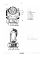
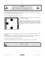
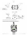
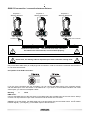
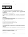
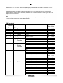
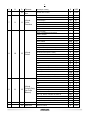
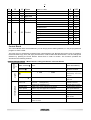
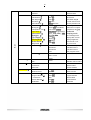
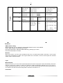
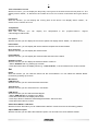
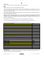
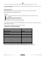
Read the user manual before turning on the product.
USER MANUAL
1 Every person involved with the installation, operation and maintenance of this device has to
- be qualified
- follow the instructions of this manual
- consider this manual to be part of the total product
- keep this manual for the entire service life of the product
pass this manual on to every further owner or user of the product
download the latest version of the user manual from the Internet
CAUTION!
Keep this device away from rain and moisture!
Unplug mains lead before opening the housing!
For your own safety, please read this user manual carefully before you initially start-up.
INTRODUCTION
Thanks for choosing a TECSHOW product. ION Series is built to satisfy the most demanding users. We are
confident that our excellent products and service will satisfy you.
Unpack the device you will find following items inside the box:
1.
2.
3.
4.
5.
6.
The fixture device
User manual
Omega holder with quick-lock fastener
DMX cable 3m
PowerCon power supply cable 1.5m
Safety rope
SAFETY INSTRUCTIONS
This device has left our factory in absolutely perfect condition. In order to maintain this condition and to ensure
a safe operation, it is absolutely necessary for the user to follow the safety instructions and warning notes
written in this user manual.
Important:
Damages caused by the disregard of this user manual are not subject to warranty. The dealer
will not accept liability for any resulting defects or problems.
CAUTION!
Be careful with your operations. With a dangerous voltage you can suffer a dangerous
electric shock when touching the wires
2 If the device has been exposed to drastic temperature fluctuation (e.g. after transportation), do not switch it
on immediately. The arising condensation water might damage your device. Leave the device switched off
until it has reached room temperature.
Please make sure that there are no obvious transport damages. Should you notice any damages on the A/C
connection cable or on the casing, do not take the device into operation and immediately consult your local
dealer.
This device falls under protection-class I. The power plug must only be plugged into a protection class I
outlet. The voltage and frequency must exactly be the same as stated on the device. Wrong voltages or
power outlets can lead to the destruction of the device and to mortal electrical shock.
Always plug in the power plug last. The power plug must always be inserted without force. Make sure that
the plug is tightly connected with the outlet.
Never let the power-cord come into contact with other cables! Handle the power-cord and all connections
with the mains with particular caution! Never touch them with wet hands, as this could lead to mortal
electrical shock.
Never modify, bend, strain mechanically, put pressure on, pull or heat up the power cord. Never operate next
to sources of heat or cold. Disregard can lead to power cord damages, fire or mortal electrical shock.
The cable insert or the female part in the device must never be strained. There must always be sufficient
cable to the device. Otherwise, the cable may be damaged which may lead to mortal damage.
Make sure that the power-cord is never crimped or damaged by sharp edges. Check the device and the
power-cord from time to time.
If extension cords are used, make sure that the core diameter is sufficient for the required power
consumption of the device. All warnings concerning the power cords are also valid for possible extension
cords.
Always disconnect from the mains, when the device is not in use or before cleaning it. Only handle the
power-cord by the plug. Never pull out the plug by tugging the power-cord. Otherwise, the cable or plug can
be damaged leading to mortal electrical shock. If the power plug or the power switch is not accessible, the
device must be disconnected via the mains.
If the power plug or the device is dusty, the device must be taken out of operation, disconnected and then be
cleaned with a dry cloth. Dust can reduce the insulation which may lead to mortal electrical shock. More
severe dirt in and at the device should only be removed by a specialist.
There must never enter any liquid into power outlets, extension cords or any holes in the housing of the
device. If you suppose that also a minimal amount of liquid may have entered the device, it must immediately
be disconnected. This is also valid, if the device was exposed to high humidity. Also if the device is still
running, the device must be checked by a specialist if the liquid has reduced any insulation. Reduced
insulation can cause mortal electrical shock.
There must never be any objects entering into the device. This is especially valid for metal parts. If any metal
parts like staples or coarse metal chips enter into the device, the device must be taken out of operation and
disconnected immediately. Malfunction or short-circuits caused by metal parts may cause mortal injuries.
HEALTH HAZARD!
Never look directly into the light source, as sensitive persons may suffer an
epileptic shock (especially meant for epileptics)!
Keep away children and amateurs!
Never leave this device running unattended.
3 OPERATING DETERMINATIONS
This device is a LED moving-head lighting effect for creating decorative effects. This product is only allowed
to be operated with an alternating voltage of 100-240 V, 50/60 Hz and was designed for indoor use only.
This device is designed for professional use, e.g. on stages, in clubs, bars, theatres etc.
Lighting effects are not designed for permanent operation. Consistent operation breaks will ensure that the
device will serve you for a long time without defects.
Do not shake the device. Avoid brute force when installing or operating the device.
Never lift the fixture by holding it at the projector-head, as the mechanics may be damaged. Always hold the
fixture at the transport handles.
When choosing the installation-spot, please make sure that the device is not exposed to extreme heat,
moisture or dust. There should not be any cables lying around. Please make sure that the unit cannot be
touched or bumped.
This device must never be operated or stockpiled in surroundings where splash water, rain, moisture or fog
may harm the device. Moisture or very high humidity can reduce the insulation and lead to mortal electrical
shocks. When using smoke machines, make sure that the device is never exposed to the direct smoke jet
and is installed in a distance of 0.5 meters between smoke machine and device. The room must only be
saturated with an amount of smoke that the visibility will always be more than 10 meters.
The ambient temperature must always be between -15° C and +45° C. Keep away from direct insulation
(particularly in cars) and heaters.
The relative humidity must not exceed 50 % with an ambient temperature of 45° C.
This device must only be operated in an altitude between -20 and 2000 m over NN.
Never use the device during thunderstorms. Over voltage could destroy the device. Always disconnect the
device during thunderstorms.
- - -m
The symbol
determines the minimum distance from lighted objects.
minimum distance between light-output and the illuminated surface must be more than this value.
The
The device must only be installed on a non-flammable surface. In order to safeguard sufficient ventilation,
leave 50 cm of free space around the device.
The housing must never touch surrounding surfaces or objects.
Make sure that the area below the installation place is blocked when rigging, derigging or servicing the
fixture.
For overhead use (mounting height >100 cm), always fix the fixture with an appropriate safety-rope. Fix the
safety-rope at the correct fixation points only. The safety-rope must never be fixed at the transport handles!
Only operate the fixture after having checked that the housing is firmly closed and all screws are tightly
fastened.The maximum ambient temperature Ta = 45° C must never be exceeded.
Operate the device only after having become familiarized with its functions. Do not permit operation by
persons not qualified for operating the device. Most damages are the result of unprofessional operation!
Please use the original packaging if the device is to be transported. Please consider that unauthorized
modifications on the device are forbidden due to safety reasons!
Never remove the serial barcode from the device as this would make the guarantee void.
If this device will be operated in any way different to the one described in this manual, the product may suffer
damages and the guarantee becomes void. Furthermore, any other operation may lead to dangers like shortcircuit, burns, electric shock, crash etc.
4
DESCRIPTION OF THE DEVICE
Features
Source
Light source: 7pcs Osram 15w 4in1 leds
Led life: 60.000 hours
Luminous Flux: 2500lumen, 15,[email protected]
Control: Remote on/off via DMX
Ballast: switching mode power supply
Optical System
Beam angle: 7°
X/Y
Pan: 360° (4.0 sec) or 540°(3.58 sec), Tilt: 265° (2.8 sec)
16-bit resolution
Auto repositioning
3 phase motor for crazily fast and quiet movement
Features
DMX channels: 14/16/22
Super fast, smooth and silent movement
RGBW four colors mixing to create vivid, saturated and uniform color effect
Virtual color wheel for color bounce
Full range 0-100% dimmer
Various strobe
RDM function to change DMX address, display flip, X/Y Reverse and so on
Software upgrade via DMX
Hibernation when lost DMX for preset time
Indicate temperature info of base, arm and lamp
Fan speed auto change according to temperature
Heat pipe for cooling
Display
24inch super nice LCD display with friendly English menu
Auto lock
Flip
Back-up communicating IC
Power
Max power consumption: 130W
Power supply: Electronic auto-ranging
Input voltage range: 100–240V, 50-60Hz
5 Overview
1
2
(1)
Head
(2)
Led
(3)
Arm (4)
Base
(5)
Wireless indicator
(6)
Display
(7)
Microphone
(8)
Left button
(9)
Down buttom
(10) Enter button
(11) Up button
(12) Right button
5
7
(13) Fuse holder
(14) Power input
(15) Power switch
(16) Power output
(17) 3-PIN DMX output socket
(18) 3-PIN DMX input socket
13
14
15 16
17
18
6 INSTALLATION
Rigging
The installation of the projector has to be built and constructed in a way that it can hold 10 times the weight for
1 hour without any harming deformation.
The installation must always be secured with a secondary safety attachment, e.g. an appropriate catch net.
This secondary safety attachment must be constructed in a way that no part of the installation can fall down if
the main attachment fails.
When rigging, derigging or servicing the fixture staying in the area below the installation place, on bridges,
under high working places and other endangered areas is forbidden.
The operator has to make sure that safety-relating and machine-technical installations are approved by an
expert before taking into operation for the first time and after changes before taking into operation another
time.
The operator has to make sure that safety-relating and machine-technical installations are approved by an
expert after every four year in the course of an acceptance test.
The operator has to make sure that safety-relating and machine-technical installations are approved by a
skilled person once a year.
Procedure:
The projector should be installed outside areas where persons may walk by or be seated.
IMPORTANT! OVERHEAD RIGGING REQUIRES EXTENSIVE EXPERIENCE, including (but not limited to)
calculating working load limits, installation material being used, and periodic safety inspection of all
installation material and the projector. If you lack these qualifications, do not attempt the installation yourself,
but instead use a professional structural rigger. Improper installation can result in bodily injury and.or
damage to property.
The projector has to be installed out of the reach of people.
If the projector shall be lowered from the ceiling or high joists, professional trussing systems have to be used.
The projector must never be fixed swinging freely in the room.
Caution: Projectors may cause severe injuries when crashing down! If you have doubts concerning the
safety of a possible installation, do NOT install the projector!
Before rigging make sure that the installation area can hold a minimum point load of 10 times the projector's
weight.
DANGER OF FIRE!
When installing the device, make sure there is no highly-inflammable
material (decoration articles, etc.) within a distance of min. 0.5 m.
7 CAUTION!
Use an appropriate clamp to rig the fixture on the truss.
Follow the instructions mentioned at the bottom of the base.
Make sure that the device is fixed properly! Ensure that
the structure (truss) to which you are attaching the fixtures is secure.
The Moving-Head can be placed directly on the stage floor or rigged in any orientation on a truss without
altering its operation characteristics (see the drawing).
The fixture’s base enables to be mounted in two ways.
For overhead use (mounting height >100 cm), always install
an appropriate safety bond.
Please note: for overhead rigging in public or industrial areas,
a series of safety instructions have to be followed that this
manual can only give in part. The operator must therefore
inform himself on the current safety instructions and consider
them.
The manufacturer cannot be made liable for damages caused by incorrect installations or insufficient safety
precautions!
Install the safety bond by inserting the quick link in the hole on the bottom of the base. Pull the safety bond
over the trussing system etc. Insert the end in the quick link and tighten the fixation screw.
The maximum drop distance must never exceed 20 cm.
A safety bond which already hold the strain of a crash or which is defective must not be used again.
DANGER TO LIFE!
Before taking into operation for the first time, the installation has to be approved by an expert!
8 2
(1)
(2)
(3)
(4)
3
Omega-holder
Clamp
Safety-rope
Quick-lock fastener
1
4
Screw the clamp via a M12 screw and nut onto the Omega-holder.
Insert the quick-lock fasteners of the Omega-holder into the respective holes
on the bottom of the device. Tighten the quick-lock fasteners fully clockwise.
9 DMX-512 connection / connection between fixtures
Projector 1
Starting address 1
Projector 2
Starting address 20
Projector 3
Starting address 39
120 Ohms
DMX-512 Controller
The wires must not come
contact with each other, otherwise
the fixtures will not work at all, or will not work properly.
Please note, the starting address depends upon which controller is being used.
Only use a DMX-cable and 3-pin XLR-plugs and connectors in order to connect the controller with the fixture
or one fixture with another.
Occupation of the XLR-connection:
If you are using controllers with this occupation, you can connect the DMX-output of the controller directly
with the DMX-input of the first fixture in the DMX-chain. If you wish to connect DMX-controllers with other
XLR-outputs, you need to use adapter-cables.
Building
a
serial
DMX-chain:
Connect the DMX-output of the first fixture in the DMX-chain with the DMX-input of the next fixture. Always
connect one output with the input of the next fixture until all fixtures are connected.
Caution: At the last fixture, the DMX-cable has to be terminated. Plug the terminator with a 120 Ω resistor
between Signal (–) and Signal (+) in the DMX-output of the last fixture.
10 Connection with the mains
Connect the device to the mains with the enclosed power supply cable.
The occupation of the connection-cables is as follows:
Cable
Pin
International
Brown
Live
L
Blue
Neutral
N
Yellow/Green Earth
The earth has to be connected!
If the device will be directly connected with the local power supply network, a disconnection switch with a
minimum opening of 3 mm at every pole has to be included in the permanent electrical installation.
The device must only be connected with an electric installation carried out in compliance with the IECstandards. The electric installation must be equipped with a Residual Current Device (RCD) with a maximum
fault current of 30 mA.
Lighting effects must not be connected to dimming-packs.
The device is equipped with a lockable power input connector. Plug in the power cord and turn it to the right
until it locks. Plug the power cord into a grounded electrical outlet that matches the rated voltage of the
machine.
OPERATION
With the power switch, you can switch the device on and off.
After you connected the effect to the mains, the fixture starts running. During the reset, the motors are
trimmed and the device is ready for use afterwards.
Stand Alone operation
In the Stand Alone mode, the model can be used without controller.
Disconnect the fixture from the controller and call the internal program.
Please refer to the instructions under Control Board.
DMX-controlled operation
You can control the projectors individually via your DMX-controller. Every DMX-channel has a different
occupation with different features. The individual channels and their features are listed under DMX-protocol.
Addressing
The Control Board allows you to assign the DMX starting address, which is defined as the first channel from
which the fixture will respond to the controller.
If you set, for example, the address to channel 20, the fixture will use the channel 20 to 38 for control.
Please, be sure that you don’t have any overlapping channels in order to control each fixture correctly and
independently from any other fixture on the DMX-chain.
If several fixture are addressed similarly, they will work synchronically.
Press the Up/Down-buttons for setting the desired starting address. Now you can start operating the fixture
via your lighting controller.
11 Note:
After switching on, the device will automatically detect whether DMX 512 data is received or not. If
there is no data received at the DMX-input, the display will flash.
This situation can occur if:
- the XLR plug (cable with DMX signal from controller) is not connected with the input of the device.
- the controller is switched off or defective, if the cable or connector is defective or the signal wires are
swap in the input connector.
Note:
It’s necessary to insert the XLR termination plug (with 120 Ohm) in the last lighting in the link in order
to ensure proper transmission on the DMX data link.
DMX-protocol
Channel
St
1
2
3
Ex1
1
2
3
4
5
Ex2
1
2
3
4
5
6
name
function
Pan
Pan fine
Tilt
Tilt fine
Movment
Speed
Pan Coarse
Movment
Function
Tilt Fine
0
0
0
0
255
255
255
255
fastest to Slowest
0
255
0
16
32
0
16
32
48
64
15
31
255
15
31
47
63
255
0
32
224
31
223
255
0
32
224
31
223
255
0
32
224
31
223
255
0
32
224
31
223
255
Pan Fine
Tilt Coarse
Normal
Movement With Backout
TBD
Normal Shutter Functions
4
6
7
Shutter
Function
Min Max
DMX DMX
Pulse-effect Forward
Pulse-effect Reverse
Random Strobe
TBD
Normal Shutter Functions
Close
Strobe Rate (slow to fast)
Open
Pulse-effect Forward
Close
Strobe Rate (slow to fast)
5
7
8
Shutter
Open
Pulse-effect Reverse
Close
Strobe Rate (slow to fast)
Open
Random Strobe
Close
Strobe Rate (slow to fast)
Open
12 6
8
9
10
Dimmer
Dimmer
fine
Dimmer(0->100%)
0
255
Dimmer fine control
0
255
0
16
32
48
64
80
112
15
31
47
63
79
111
255
0
223
224
232
240
248
231
239
247
255
0
255
0
255
0
1
2
3
4
46
88
130
172
214
0
1
2
3
45
87
129
171
213
255
0
1
2
3
4
46
88
130
172
214
0
0
0
1
2
3
45
87
129
171
213
255
255
255
On Function
CTC Function
7
9
11
Virtual
Color
Function
Forward Spin
Reverse Spin
Continuous
Color Bounce
TBD
CTC Function
Colour Temperature Correction
2000K->2700K
White 3200K
White 4200K
White 5600K
White 8000K
Forward Spin
Rainbow Effect (Slow->Fast)
Reverse Spin
8
10
12
Virtual
Color1
Rainbow Effect (Slow->Fast)
Continuous&Color Blonce
Black
Red
Green
Blue
Red=0, Green->up,Blue=full,White=0
Red=0, Green=full,Blue->down,White=0
Red->up, Green=full,Blue=0,White=0
Red=full, Green->down,Blue=0,White=0
Red=full, Green=0,Blue->up,White=0
Red->down, Green=0,Blue=full,White=0
Color Blonce
Black
Red
Green
9
11
13
Virtual
Blue
Color2(Only Red=0, Green->up,Blue=full,White=0
On Color
Red=0, Green=full,Blue->down,White=0
Blance)
Red->up, Green=full,Blue=0,White=0
Red=full, Green->down,Blue=0,White=0
Red=full, Green=0,Blue->up,White=0
Red->down, Green=0,Blue=full,White=0
10
12
14
15
Red
Red fine
Red 0->100%
Red fine control
13!
11
12
13
13
14
15
16
17
18
19
20
21
Green
Green fine
Blue
Blue fine
White
White fine
0
0
0
0
0
0
0
8
16
24
56
64
72
80
88
96
Green 0->100%
Green fine control
Blue 0->100%
Blue fine control
White 0->100%
White fine control
Normal
Reset All
Pan&Tilt Reset
TBD
14
16
22
Display Off
Control
Display On
TBD
TBD
Hibernation
TBD
255
255
255
255
255
255
7
15
23
55
63
71
79
87
95
255
Control Board
The Control Board offers several features: you can simply set the starting address, run the pre-programmed
program or make a reset.
The main menu is accessed by pressing Enter until the display is lit. Browse through the menu by pressing
the arrow buttons (up, down, left, right). Press Enter in order to select the desired menu. You can change the
selection by pressing the arrow buttons. Press Enter in order to confirm. The functions provided are
described in the following sections.
Connec
t
Default settings shaded. 1 Basic Reload / 2 Program Reload / 3 Private Reload
DMX Address
DMX addresssetting
Wireless
Max
Light
XXX
Temperature
Wireless Enabled
80~139 , 90
/176~282
, 194
L amp off if temperature
continuously over for 5
minutes
Lamp Adjust
PAN……
Adjust value of each
channels
Information
Time Info.
Current
XXXX(Hours)
Fixture Life XXXX(Hours)
Near Lamp Temp (depends on fixture)
Fixture boot time
Fixture total run time
Temperature Sensors
Fans Speed
Near Lamp Fan (depends on fixture)
Fan speed Sensors
Channel Value
PAN……
D isplay value of channel
Error Message
Pan,Tilt… …
Error channels
Fixture Model
xxxxxxxxxxxx
Display model brand
and model
1U01 V1.0.00
Version of each IC
Temperature
Software Ver
2U01 V1.0.00
14!
Reset
All
Reset all
Pan&Tilt
Movment
ON/OFF
Pan Reverse
Tilt Reverse
ON/ OFF
630/ 540
Tilt Reverse
ChoosePan Degre
e
Pan Degree
Encoders
UI Set
ON /OFF
Encoder wheel on/off
Pan/Tilt Mode
Stand /Smooth
Choose pan/tilt mode
Mic Sens.
0~99%, 60%
Sensitivity of Mic
No Signal
Close/ Hold /Auto/Music
Mode when no signal
Temperature at /
Temperature. C/F
Fahrenheit / Celsius
Fans Mode
Auto Speed /High Speed
User Mode
Standard
Extended 1
Extended 2
User
Standard mode(16bit)
Extended mode 1
Extended mode 2
User program mode
Edit User
Max Channel = XX
PAN = CH01
Edit users mode
Calibration
-Password Pan..
=XXX
=XXX
Password: 050
Calibrate channel value
Fixture ID
Name
-PasswordPID Code
Wireless Set
DMX On Cable
Reset Connect
ON/ OFF
ON/ OFF
Basic Reload( )
Program Reload( )
---Password --Private Reload( )
ON/ OFF
ON/ OFF
XXX
ON/ OFF
ON/ OFF
Hibernation
Backlight
Flip Display
Display Bright
Brand Show
Key Lock
Set
Reset Pan&Tilt
Pan Reverse
Users
Fansmode
OFF, 01M~99M 15M Sleeping mode
02~60m 02m
Show backlight time
ON/OFF
Display 180 reverse
00~31 10
Display Brightness
ON/OFF
Show brand or not
ON/OFF
Key lock on/off
:
Reload Default
All Reload
Name
Password: 050
Set PID of RDM
DM X Send Out
Reset Connect
Basic Reload
Program Reload
Password:050
Private Reload
All Reload
15!
Play
DMX Receive
Slave Receive
Sequence
Slave Reveice 1,2,3
Master / Alone
Choose slave position
Run Sequence
Music
Chase Part 1
Master / Alone
Chase 1 ~ 8 Chase 1
Chase Part 2
Chase Part 3
Chase 1 ~ 8 Chase 2
Chase 1 ~ 8 Chase 3
Music mode
Select and run
auto program
Edit Chase
Chase 1
Chase Test
Edit Scenes
:
Chase 8
Edit Scene 001
Step 01
Step 64
Pan,Tilt,……
Select Chase
Program
DMX Receive
~ Edit Scene 250
--Fade Time ---Scene Time -DMX Input
=SCxxx
=SCxxx
=xxx
=xxx
=xxx
Test
Beginning scene
Ending scene
Input manual scene
Modify manually fading
time
Modify manually scene
time
Input
scene
exterior controller
Scenes Record
ScXX=>ScXX
from
Auto Input scenes
Connect
DMX address setting
With this function, you can adjust the desired DMX-address via the Control Board.
Select “DMX Address“ by pressing Up or Down.
Press the Enter-button, adjust the DMX address by pressing Up or Down.
Press the Enter-button to confirm.
Wireless
With this function, you can enter wireless mode, then no need signal cable connection, in this mode
signal still transmitted by cable if the signal cables are connected, if want to send signal via wireless
cables must be disconnected.
Light
MaxTemperate
With this function you can set the inside temperature at which the projector will automatically switch the
LED off. Press Up or Down to select the maximum inside temperature between 80 °C and 139 °C.
Inside temperatures below 90 °C are not critical. 90 °C and more should lead to the LED being switched
off. Please note that the outside temperature should not exceed 45 °C.
Information
16 Time information Current
With this function, you can display the temporary running time of the device from the last power on. The
display shows “XXXX”, “X“ stands for the number of hours. The counter is reset after turning the device
off.
Fixture Life
With this function, you can display the running time of the device. The display shows “XXXX”, “X“
stands for the number of hours.
Temperature
Near lamp Temp
With this function you
Celsius/degree Fahrenheit.
...
can
display
the
temperature in
the
projector-head in
degree
Fan speed
With this function you can display the current fan speed. The display shows “XXXX”, “X“ stands for Hz.
Initial status
With this function, you can display with which value the respective channels will start.
Error channels
With this function, you can display the channel errors.
Fixture Model
With this function, you can display the model number and brand of the fixture.
Software version
With this function you can display the software version of each IC.
• Select “Software ver.” by pressing Up or Down.
• Press the Enter-button, the display shows e.g. “1U01 VX.X.XX”, “X.X.XX“ stands for the version number.
Set
Reset
With this function you can reset the device via the Control Board. You can select the different Resetfunctions by pressing Up or Down.
Movement
PAN Reverse
With this function you can reverse the PAN-movement.
TILT Reverse
With this function you can reverse the TILT-movement.
PAN degree
With this function you can select the PAN-degree.
• Select “PAN degree” by pressing Up or Down.
• Press the Enter-button, the display shows “540”.
• Press Up or Down to select the desired degree between “540” and “630”.
• Press the Enter-button to confirm.
Automatic PAN/TILT calibration
With the function "Encoders" you can calibrate the PAN/TILT movement to the correct starting position.
Adjust PAN/TILT speed
With this function you can define the PAN/TILT speed. You can select one of two different modes.
17 UI Set
Mic sensitivity
With this function, you can select the desired microphone sensitivity between 0 % and 99 %.
• Select “Mic Sens” by pressing Up or Down.
• Press the Enter-button.
• Press Up or Down to select the desired sensitivity.
• Press the Enter-button to confirm.
No DMX status
With the function "No Signal", you can set different modes if there is no DMX-signal.
• Select "Close, Hold, Auto or Music" by pressing Up or Down.
• Press Up or Down to select between "Close", "Hold", "Auto" or "Music".
• Press the Enter-button to confirm.
Select temperature designation
With this function you can select the temperature designation.
• Select “Temperature C/F” by pressing Up or Down.
• Press Up or Down to select the desired degree between “Celsius” and “Fahrenheit”.
• Press the Enter-button to confirm.
Hibernation - power standby mode
With this function you can put the device in the power standby mode. This function will be automatically
activated after a predefined period of time of no DMX activity. In standby mode the lamp/LEDs and all motors
will power down if no DMX signal is sent to the fixture for a period of e. g. 15 minutes (can be user defined).
The fixture will automatically reset and return to normal operation once a DMX signal is sendet.
Backlight
With this function you can shut off the display after 2 to 60 minutes.
Flip Display
With this function you can flip the display by 180° for a better view when the fixture is hung from the truss or a
ceiling.
Brand Show
With this function you can show or hide the brand name 'TECshow' on the display during
menu operation, but still show it after reset.
Key lock
With this function you can lock the keys of the Control Board to e.g. prevent menu tampering. If this function is
activated, the keys will be automatically locked as soon as exit the menu. In order to deactivate or temporarily
deactivate the keylock function, press the button UP-DOWN-LEFT-RIGHT-ENTER regain access to the menu
commands.
Users
User mode
With this function, you can create user defined channel orders.
Edit User
With this function, you can adjust the Preset user defined channel order.
Calibration
With this function, you can calibrate and adjust the effect wheels to their correct positions. The password for
this function is „050“.
Fixture ID
18 Wireless Set
Mode 1 = TECshow, Mode 2 will compatible with Wireless Solution signal.
RDM
With this function you can call up various submenus via RDM.
This device is RDM ready. RDM stands for "Remote Device Management" and makes remote control of
devices connected to the DMX-bus possible. ANSI E1.20-2006 by ESTA specifies the RDM standard as an
extension of the DMX512 protocol.
Manual settings like adjusting the DMX starting address are no longer needed. This is especially useful when
the device is installed in a remote area.
RDM is integrated in DMX without influencing the connections. The RDM-data is transmitted via the standard
XLR-poles 1 and 2 – new DMX-cables are not necessary. RDM ready and conventional DMX devices can be
operated in one DMX line. The RDM protocol sends own packages in the DMX512 data feed and does not
influence conventional devices.
If DMX splitters are used and RDM control is to be used, these splitters must support RDM.
The number and type of RDM parameters depend on the (optional) RDM controller being used.
In general, the device supports the following commands and functions via RDM:
RDM Parameter ID's (Slot 21-22)
Category _Network Management
DISC_UNIQUE_BRANCH
DISC_MUTE
DISC_UN_MUTE
Category -RDM Information
SUPPORTED_PARAMETERS
PARAMETER_DESCRIPTION
Category _Product Information
DEVICE_INFO
DEVICE_MODEL_DESCRIPTION
MANUFACTURER_LABEL
DEVICE_LABEL
FACTORY_DEFAULTS
SOFTWARE_VERSION_LABEL
Category -DMX512 Setup
DMX_PERSONALITY
DMX_PERSONALITY_DESCRIPTION
DMX_START_ADDRESS
SLOT_INFO
SLOT_DESCRIPTION
Category _Sensors
SENSOR_DEFINITION
SENSOR_VALUE
Category _Power/Lamp Settings
DEVICE_HOURS
Category -Display Settings
DISPLAY_INVERT
Category _Configuration
PAN_INVERT
TILT_INVERT
Category _Control
IDENTIFY_DEVICE
RESET_DEVICE
Value
0x0001
0x0002
0x0003
0x0050
0x0051
0x0060
0x0080
0x0081
0x0082
0x0090
0x00C0
0x00E0
0x00E1
0x00F0
0x0120
0x0121
0x0200
0x0201
0x04xx
0x0400
0x0500
0x0600
0x0601
0x1000
0x1001
Reload Default
With this function you can restore the factory settings of the device. The different settings (marked in the
table) will be set back to the default values (shaded).
19 Program
Play
Slave Revice
With this function, you can define the device as slave. You can choose one of
programs. For further information see „Edit Chase”.
three different Slave
Sequence
With this function, you can run the internal program. You can select the desired program under “Select
Chase”. You can set the number of steps under “Edit Chase”. You can edit the individual scenes under “Edit
Scenes”. With this function, you can run the individual scenes either automatically, i.e. with the adjusted
Step-Time. The selection "Alone" means Stand Alone-mode and "Master" that the device is defined as master.
Music
With this function, you can run the internal program sound-controlled. The selection "Alone" means Stand
Alone-mode and "Master" that the device is defined as master.
Select chase for auto program
With this function, you can select the program for the Program Run.
Edit chase
With this function, you can edit the internal programs.
Edit scenes
With this function, you can edit the scenes of the internal programs.
Rec. Controller
The device features an integrated DMX-recorder by which you can transmit the programmed scenes from your
DMX-controller to the device. Adjust the desired scene numbers by pressing Up or Down (from – to). When
you call up the scenes at your controller, they will automatically be transmitted to the device.
Excursion:
A Master unit can send up to 3 different data groups to the Slave units, i.e. a Master unit can start 3 different
Slave units, which run 3 different programs. The Master unit sends the 3 program parts in a continuous loop.
The Slave unit receives data from the Master unit according to the group which the Slave unit was assigned to.
If e.g. a Slave unit is set to „Slave 1“ in the menu „Set to Slave“, the Master unit sends „Auto Program Part 1“
to the Slave unit. If set to „Slave 2“, the Slave unit receives „Chase Part 2“.
To start a Auto Program please proceed as follows:
1.Slave-Setting
• Select “Program” by pressing Up or Down.
• Press the Enter-button to confirm.
• Select “Slave” by pressing Up or Down.
• Press the Enter-button to confirm.
• Press Up or Down to select “Slave 1”, “Slave 2” or “Slave 3”.
• Press the Enter-button to confirm.
2. Automatic Program Run
• Select “Program” by pressing Up or Down.
• Press the Enter-button to confirm.
• Select “Sequence” by pressing Up or Down.
• Press the Enter-button to confirm.
• Press Up or Down to select “Master” or “Alone”. The selection "Alone" means Stand Alone-mode and
"Master" that the device is defined as master.
• Press the Enter-button to confirm.
20 3. Program for Select Chase
• Select “Edit Chase” by pressing Up or Down.
• Press the Enter-button to confirm.
• Select “Select Chase” by pressing Up or Down.
• Press the Enter-button to confirm.
• Press Up or Down to select “Chase Part 1”, “Chase Part 2” or “Chase Part 3”, and thus select which
Slave program is to be sent. Selection „Part 1“ means, that the Slave unit runs the same program as the
master units.
• Press the Enter-button to confirm.
4. Program selection for Edit Program
• Select “Edit Chase” by pressing Up or Down.
• Press the Enter-button to confirm.
• Select “Edit Chase” by pressing Up or Down.
• Press the Enter-button to confirm.
• Press Up or Down to select the desired program. With this function you can edit specific scenes into a
specific program.
• Press the Enter-button to confirm.
5. Automatic Scene Recording
• Select “Edit Chase” by pressing Up or Down.
• Press the Enter-button to confirm.
• Select “Edit scenes” by pressing Up or Down.
• Press the Enter-button to confirm.
• Press Up or Down to select the desired scene numbers. You can program a maximum number of 250
scenes.
• Press the Enter-button to confirm.
• Press Up or Down to select the desired value.
• Press the Enter-button to confirm.
Example:
Program 2 includes scenes: 10, 11, 12, 13;
Program 4 includes scenes: 8, 9, 10 and
Program 6 includes scenes: 12, 13, 14, 15, 16
Chase Part 1 is Program 2;
Chase Part 2 is Program 3;
Chase Part 3 is Program 6
The 3 Slave groups run the Auto Program in certain time segments, as shown in the following picture:
21 Error Messages
When you turn on the fixture, it will make a reset first. The display may show an error message while
there are problems with one or more channels. The error message stands for the channels equipped
with a testing sensor.
For example, when the display shows “Err channel PAN”, it means there is some error in the
horizontal movement (PAN), control-channel 1. If there are some errors on several channels at the
same time, you may see the error messages flash repeatly for 2 times, and then the fixture will
generate a reset signal, all the stepper motors will reset. If the error messages maintain after
performing reset more than 2 times, only the channels which have errors can not work properly,
others can work as usual.
The respective error message will appear after the reset of the fixture if the channels magnetic-indexing
circuit malfunction (sensor failed or magnet missing) or the stepping-motor is defective (or its driving IC on the
main PCB). The channel feature is not located in the default position after the reset.
The different error messages are:
PAN
TILT
CLEANING AND MAINTENANCE
The operator has to make sure that safety-relating and machine-technical installations are inspected by an
expert after every four years in the course of an acceptance test.
The operator has to make sure that safety-relating and machine-technical installations are inspected by a
skilled person once a year.
The following points have to be considered during the inspection:
1) All screws used for installing the devices or parts of the device have to be tighly connected and must not be
corroded.
2) There must not be any deformations on housings, fixations and installation spots (ceiling, suspension,
trussing).
3) Mechanically moved parts like axles, eyes and others must not show any traces of wearing (e.g. material
abrading or damages) and must not rotate with unbalances.
4) The electric power supply cables must not show any damages, material fatigue (e.g. porous cables) or
sediments. Further instructions depending on the installation spot and usage have to be adhered by a
skilled installer and any safety problems have to be removed.
DANGER TO LIFE!
Disconnect from mains before starting maintenance operation!
We recommend a frequent cleaning of the device. Please use a moist, lint-free cloth. Never use alcohol or
solvents!
CAUTION!
The lens has to be replaced when it is obviously damaged,
so that its function is impaired, e. g. due to cracks or deep scratches!
The objective lens will require weekly cleaning as smoke-fluid tends to building up residues, reducing the
light-output very quickly. The cooling-fans should be cleaned monthly.
22
The interior of the fixture should be cleaned at least annually using a vacuum-cleaner or an air-jet.
There are no serviceable parts inside the device. Maintenance and service operations are only to be carried
out by authorized dealers.
Replacing the fuse
If the fine-wire fuse of the device fuses, only replace the fuse by a fuse of same type and rating.
Before replacing the fuse, unplug mains lead.
Procedure:
Step 1: Unscrew the fuseholder on the rearpanel with a fitting screwdriver from the housing (anticlockwise).
Step 2: Remove the old fuse from the fuseholder.
Step 3: Install the new fuse in the fuseholder.
Step 4: Replace the fuseholder in the housing and fix it.
Should you need any spare parts, please use genuine parts.
If the power supply cable of this device becomes damaged, it has to be replaced by a special power supply
cable available at your dealer.
Should you have further questions, please contact your dealer.
TECHNICAL SPECIFICATIONS
Power supply:
Power consumption:
DMX control channels:
DMX512 connection:
Sound-control:
Type of LEDs:
Number of LEDs:
Beam angle:
Maximum PAN-movement:
Maximum TILT-movement:
Dimensions (LxWxH):
Weight:
Maximum ambient temperature Ta:
Maximum housing temperature TB (steady state):
Min.distance from flammable surfaces:
Min.distance to lighted object:
Fuse:
100-240 V AC, 50/60 Hz ~
130 W/215 VA
14/16/22
3-pin XLR
via built-in microphone
Osram 15w 4in1
7
approx. 7°
630°
270°
244x 179 x 322 mm
4 kg
45° C
60° C
0.5 m
0.3 m
T 2 A, 250 V
Please note: Every information is subject to change without prior notice. 10.09.2012
G
QUALITY
&
HTING
LIG
IN
ERFORMAN
P
D
CE
O
O
THANK YOU
FOR YOUR TRUST
www.american-pro.com
AMERICAN PRO develops & improve products constantly.
For this reason, the specifications and consigned information in the present user manual
can me modified without notice