1
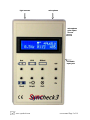
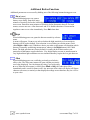
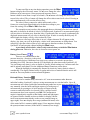
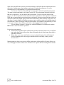
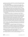
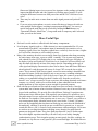
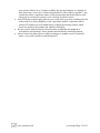
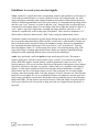
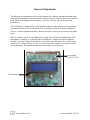
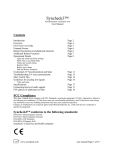
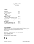
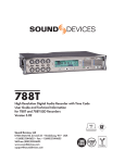
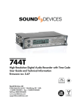
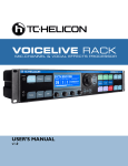
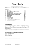
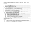
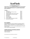
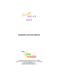
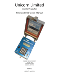
Syncheck3™
Synchronization verification tool
User Manual
Contents
Introduction
Overview
First Time Use Guide
Example Screen
Button Descriptions
Additional Button Functions
Operational Details
Light and sound sensitivity settings
Mask Time, Long Mask Mode
Frames per second setting
Relative Offset
Battery saver timers
Halt and History Functions
Understand AV Synchronization and Span
Troubleshooting AV sync measurements
More Useful Tips
Guidelines for creating test signals
Page 3
Page 4
Page 5
Page 6
Page 6
Page 7
Page 8
Page 8
Page 8
Page 8
Page 9
Page 9
Page 11
Page 13
Page 14
Page 16
Video and audio
Specifications
Connecting line level audio signals
Internal adjustments
FTP address of additional test files
Page 17
Page 17
Page 18
Page 19
FCC Compliance
This class A digital device complies with FCC Standards, in particular paragraph 15.103(c). Operation is subject to
the following two conditions: (1) This device may not cause harmful interference, and (2) this device must accept
any interference received, including interference that may cause undesired operation.
Changes or modifications not expressly approved by Pharoah Editorial, Inc. could void the user’s authority to
operate the equipment.
Syncheck3™ conforms to the following standards:
EN55103-1 Electromagnetic emission
EN55103-2 Electromagnetic immunity
EN61000-4-3 RF Immunity
EN61000-4-8 Magnetic field
Syncheck3 is lead free and RoHS compliant
www.syncheck.com
user manual Page 1 of 19
light sensors
microphone
microphone
gain adjust
access
line audio
input jack
www.syncheck.com
user manual Page 2 of 19
Syncheck3™
Synchronization verification tool
User Manual
Syncheck3™ is a unique product designed to help you accurately and efficiently evaluate
the timing relationship between sound and image from your editing and viewing equipment.
Proper synchronization of sound and image is essential for maintaining lip sync and making
good editing choices during professional media production. Because many technical factors can
each ruin the synchronization relationship, an objective measurement tool such as Syncheck3 is
invaluable in finding, evaluating, and reducing them. Syncheck3 will be the first tool you reach
for when setting up or adding components to an editing or playback system, and anytime you
want to verify that picture and sound are presented in proper synchronization.
CAUTION: legal disclaimer follows.
Syncheck test files use repeating white flashes similar to a strobe effect. Some
people have sensitivity to repeating flashes, which may cause physical
discomfort or seizures during testing! USE OUR TEST SIGNALS ONLY AT
YOUR OWN RISK! You may wish to lower room lights a bit but do not
extinguish them. Repeated flashes in a darkened room can cause discomfort or be
downright hazardous to your health. Consider yourself forewarned and remember
that you can use single, isolated flash-pips instead of repeating patterns. We are of
the opinion that “one per second” flash/pip patterns present a reasonably low risk
but they are NOT risk free for some people. Do NOT use our rapidly repeating
“multi-spaced” flash patterns unless you are willing to accept their increased health
risks. It is recommended to keep your room lights on to reduce risks further and
help your shins remain bruise free.
www.syncheck.com
user manual Page 3 of 19
Overview
Syncheck3 contains light detectors and a microphone that detect light and sound. (A line
level audio input jack is also provided.) Test videos consist of repeating white flash frames with
simultaneous audio “pips” (bursts of sine tone). Repeating “flash-pips” allow accurate testing of
both interlaced and progressive displays with equal effectiveness. A single flash-pip is enough to
provide an accurate measurement at that moment in time. Our test signals repeat continuously to
reveal intermittent errors or changes over time.
Syncheck3 registers the leading edge of each sound and light burst, tells you which was
ahead of the other, and how much time occurred between them. The onset of sound and the
moment of change from dark to bright are the points in time used for measurement. Syncheck3’s
optical detectors are very sensitive to a wide range of visible and near-infrared light and work
well with practically any display technology. The microphone’s adjustable sensitivity range is
more than adequate for most situations.
Test movies have been authored with a range of codecs and frame rates. Because there
are many more movie files than will fit on a single disc we have selected a group of commonly
used files for inclusion with your purchase. All of our movie files are available via ftp (see the
last page of this manual.) If you purchased an optional playable DVD-R disc you also received a
subset of test files in the data area of the DVD. If you wish, you can create your own test files
using guidelines discussed in this manual.
Syncheck test movies are broadly grouped by codec as “one per second” or “multispaced” types. “One per second” test signals repeat at a rate of one flash-pip per second. “Multispaced” signals repeat more rapidly. Most movies are authored in 29.97, 25, 24, and 23.976
frames per second versions, and sometimes also 50 and 59.94. Use of standard definition files on
high definition systems is perfectly acceptable. Any of our files can be up-converted or down
converted to any resolution required. As long as a test file’s frame rate is maintained, up/down
conversion will have no effect on measurement results.
“One-per-second” flash-pip movies are recommended for most uses and should always
be used for initial measurements. Their slow repetition rate allows measurement of offset errors
up to ½ second. “Multi-spaced” movies are considerably faster paced. The time between
flash/pips varies between 5 and 12 frames, often with a distinctive pattern. Once a system’s AV
error is known to be less than 4 video frames, the faster pace of “multi-spaced” patterns is best at
revealing subtle drifting or intermittent errors.
Once AV error has been determined, several techniques can be used to correct the
problem. More often than not, audio plays ahead of video as a result of image processing
demands within video equipment and monitors. Some workstations provide adjustments that are
typically able to reduce errors to within a single video frame. Effective results rely on accurate
measurement and compromise. When audio is ahead of video a very effective solution is to
introduce a delay into the audio monitoring path. Some home theater systems provide adjustable
audio delays that can be used for this purpose. In cases where video is ahead of audio, the
solution may not be as simple. High quality video delays are very expensive and thus it may be
more practical to use video equipment with lower processing delays. It is fortunate indeed that
this situation is not very common.
www.syncheck.com
user manual Page 4 of 19
Checking Audio/Video sync error for the first time
1. Perform your first test in a quiet room with low light. Bright ambient light may affect results.
Start with lowered lights (total darkness is not necessary) until you are comfortable with
Syncheck3’s operation. Noise from nearby activity and talking should be avoided, otherwise
random sound may be detected and cause strange measurements.
2. Install a FRESH 9 volt battery. Need we say more? Even though Syncheck3 is very tolerant of
battery weakness we cannot guarantee accuracy when using a battery of weak or unknown
reserves.
3. Load an appropriate test file. For quick practice simply open one of our test movies in a media
player such as QuickTime or Windows Media Player. To measure a workstation’s performance,
import audio and video from a file that matches your system’s frame rate: 29.97, 25, 24, or
23.976 frames per second. (You have a range of files to pick from. Different codecs and data rates
often perform differently. We suggest starting with standard resolution DV movies.) To extend
playback time, duplicate the movie back-to-back several times. Looped playback is not advised.
Some systems cannot maintain audio-video synchronization during looped playback.
4. Turn on Syncheck3. Push the FPS button. (FPS = “Frames Per Second”) The FPS menu opens.
Use + and – to set an appropriate frame rate. For fractional rates such as 23.976 or 29.97, select
the closest FPS choice, e.g. select 24 or 30. Press FPS or Halt to exit the menu. (Tip: Halt will exit
from all menus.) This setting determines how time measurements are displayed in frames per
second values. Milliseconds measurements are accurate no matter what FPS value is selected.
5. Play the test movie and adjust audio pips to a comfortable listening level. Your playback
volume must be high enough to animate a small graphic character near the center of the display’s
top line. This sound “icon” must fluctuate in exact step with audible pips. In a noisy environment
where stray sounds cause unwanted detections you may bypass the microphone entirely by
connecting an unbalanced audio signal directly through a mini XLR connector. (Note: our mini
XLR wiring scheme is non-standard, explained elsewhere in this manual)
6. Point Syncheck3 toward your flashing video display. The monitor icon graphic (next to the
sound icon) must animate in exact step with flashing video. If it does not, try moving closer to or
further from your screen. If your video display is very bright or if the monitor icon remains
activated during the dark portions of test movies, try pressing (and holding) the Bright button
during measurement. This will alter Syncheck3’s light sensitivity.
7. Read the amount of audio-video timing error. Syncheck3 will display “Video←” when light
arrives before sound, or “→Audio” when sound arrives first. In the unlikely case that sound and
light arrive within ½ millisecond of each other, both words appear. Invalid measurements display
as zero error time and neither word appears. AV Error, the difference between sound and light
arrival times, is displayed simultaneously as milliseconds and as frames per second.
8. Readings may seem to jump around or slowly change values. Inconsistent readings are
common with many playback system configurations. The variations are usually less than ½ video
frame of total change. Syncheck3 is not broken! Read “Understanding AV Synchronization and
Span”. Also, most displays build images from top to bottom. You may notice small measurement
differences when Syncheck3 is pointed to upper vs. lower portions of a screen. This may be
unavoidable and is discussed further in the manual under “More Useful Tips”.
www.syncheck.com
user manual Page 5 of 19
Example Screen
A typical screen display is captured at right.
This screen shows Syncheck3 has been set for
48 frames per second. For the most recently
detected flash-pip, audio arrived ahead of
video by .54 frames or 11 milliseconds. (If
video had been ahead, “Video←” would be
displayed in the space to the left and “→Audio” would not appear.) There are two graphic icons
in the center of the top line. The icon on the left follows light input; we refer to it as the “monitor
icon”. Immediately to its right is the “sound icon” which follows sound/audio input. In this
example, a light flash is currently being detected. No audio is currently detected.
Button Descriptions
Bat shares a button with +. Press to clear the history buffer during real-time
measurement. Hold during power on to access battery saver features. See
additional functions below.
FPS opens a frames per second entry menu. Change frames per second value with + –.
Press FPS or Halt to exit
Offset opens the relative offset menu. Enter value with + and –. Hold + or – for rapid
adjustment. Press + and – together to reset to zero. Press Offset or Halt to exit. See
additional functions below.
Mask shares a button with –. During real-time measurement Mask invokes long mask
mode (see operational details below). Short mask mode is restored when the button is
released.
Bright has three uses. Press during measurement to toggle light sensor sensitivity setting
(low/high). Hold down during power on to define which light sensor setting is default
(see additional functions below). Hold Bright to adjust lcd backlight with + or –.
Halt has two uses. During real-time measurement, press to immediately stop
measurement and enter Halt mode. See “Halt and History Functions”. Halt can close
any open menu.
+ –
Enter/change values in menus. (– is shared by Mask function, + is shared by Bat function)
Hold – during power on to see software version number.
www.syncheck.com
user manual Page 6 of 19
Additional Button Functions
Additional parameters are accessed by holding one of the following buttons during power on.
Bat (+ button)
When held during power on, opens a
battery saver dialog. Enter how many
minutes of inactivity before the lcd backlight automatically dims. Press Halt to proceed to the
next screen. Enter how many minutes of inactivity before automatic shut off. For both
menus, use + or – to set a value between 0 and 99. 0 disables that timer. Press + and –
together to enter a zero value immediately. Press Halt when done.
Bright
When held during power on, opens the detector sensitivity selector
menu.
A menu will appear. Use + or – to select whether the high sensitivity or low sensitivity
detector will be used as default. Your selection is saved when you exit the menu. (Press
either Bright or Halt to exit.) Whichever choice you make on this menu will determine which
detector is normally used during measurement, whenever the Bright button is NOT held
down. The high gain detector (factory default) is usually the best choice unless your
particular circumstances require otherwise. Very bright display screens or measurement in
very high ambient light conditions are two situations that may require the low gain detector.
Offset
When held during power on, recalls the previously used relative
offset value. The offset entry menu will open with the previouslyused value displayed. You can change the value if you wish using
+ or –. When the offset menu is closed (Press Offset or Halt), the value takes effect
immediately and is saved for future recall. Any non-zero offset value will display a Σ Sigma
character on screen, to remind you that displayed readings are not absolute, they are relative
to your value.
www.syncheck.com
user manual Page 7 of 19
Operational Details
Light and Sound Sensitivity Settings
There are two light detectors built into Syncheck3. The Low Gain detector has lower
light sensitivity than the High Gain detector. Either can be selected as the default to be used
normally (see Additional Button Functions to locate that menu setting). Syncheck3 will
temporarily switch from the default detector to the other while you press and hold the Bright ☼
button. This is a real-time toggle during measurement, not a menu’d selection. For example, the
factory default detector is the High Gain detector. Unless you change the default setting, pressing
the Bright button temporarily selects the Low Gain detector for measurement, and upon button
release high sensitivity is restored. The monitor icon’s shape is smaller when gain is low.
Microphone gain can be adjusted via a trimmer potentiometer available through the side
of the case. This adjustment does not affect line input gain through the mini-XLR.
Mask Time
Immediately after Syncheck3 detects a flash or pip signal, there is a brief period during
which it ignores other sound or light input. This important feature is called “mask time”.
Syncheck3’s normal mask time of 137 milliseconds was chosen to allow reliable detection of
rapidly repeating flash-pips in typical sound rooms with well controlled reverb characteristics. If
you are working in a reverberant location you may benefit from much longer mask times. A 900
millisecond mask can be invoked by pushing and holding the Mask button during measurement.
The normal 137ms mask time will be restored when the Mask button is released. This is a realtime change during measurement, not a menu’d selection. The sound icon will change shape
when mask time is altered.
We recommend using test signals with repetition rates no faster than one per second. Our
one-per-second flash-pip files work well with long mask times. Multi-spaced movies are never
recommended with Syncheck3’s long mask time. Repetition rates slower than once per second
might be required in extreme circumstances but we have not tested under such conditions. We
have not authored any files with repetition rates slower than one per second, but there is no
reason that very slow repetition rates should not work.
Frames per second
For accurate readouts by Syncheck3, select a frames per second
value that matches your video system and/or video stream. Press FPS
to open a menu and use + or – to change the value. FPS or Halt will
exit and save the new fps value. The FPS setting only affects Syncheck3’s calculation of frames
per second error times. Milliseconds calculations are not affected. This menu can be called
during real-time operation or while Halt mode is in effect.
Relative Offset
It is possible to enter an offset to Syncheck3’s Audio/Video error measurement. This
user-entered value will be added or subtracted from the actual measurement before the result is
displayed. Syncheck3 will then show an amount of deviation away from the offset time you
entered. Your offset value is saved and may be optionally recalled the next time you use
Syncheck3. Only one offset value is saved. To recall the previously used offset, hold the Offset
button during power on. If the Offset button is not held when the unit is turned on, the relative
offset is reset to zero automatically and the offset entry menu is not opened.
www.syncheck.com
user manual Page 8 of 19
To enter an offset at any time during operation, press the Offset
button to display the offset entry menu. Use + or – to change the value.
Hold + or – for auto-repeat. (Auto-repeat speed increases when a
button is held for more than a couple of seconds.) The + button will change the offset value
toward video ahead. The – button will change the offset value toward audio ahead. Pressing +
and – simultaneously will reset the offset to zero.
The value is always entered as whole milliseconds, with a
frames-per-second equivalent displayed (calculated according to your
frame rate setting). Press Offset or Halt when done.
The example screen just above this paragraph shows a relational offset has been entered,
that audio is desired to be ahead of video by 42 milliseconds. Syncheck3’s measurement displays
will now show a deviation away from that value. If audio and video are exactly synchronous, the
displayed measurement will say video is ahead by 42ms. If audio is actually ahead by only 20
milliseconds, the display will say video is ahead by 22ms.
Whenever a non-zero offset value is in use, a Sigma character Σ will appear on the
display. Any time you see Σ in the display, relative error measurements are being shown. You
can quickly clear the relative offset to zero, and return to absolute readouts, by turning
Syncheck3 off and on again without holding the Offset button.
A previously-saved relative value is only restored when you hold the Offset button
during power on. Otherwise, the value is cleared to zero at power on.
Battery Saver Timers
There are two internal timers that
measure inactivity. (Inactivity is the period
between switch presses.) Both timers are reset to zero whenever a switch is pressed (not
including On or Off). One timer dims the LCD backlight, the other timer turns Syncheck3 off.
You can change each timer’s value or disable it. Factory default settings are 5 minutes until dim
and 10 minutes until shutoff. See the Additional Button Functions section above.
When the backlight is automatically dimmed by inactivity, battery drain is reduced
considerably. The display flashes briefly at regular intervals as a reminder that the unit is still
turned on. Press any button to restore normal brightness.
Halt and History Functions
It is wise to consider many consecutive AV error measurements rather than one
individual reading. Syncheck3 is always saving measurements to a circular buffer. Up to 40
measurements are retained with oldest measurements pushed out as new ones are captured. You
may manually clear the buffer and begin capture of a fresh group of
measurements by pressing +. (A brief message will appear on the
screen to confirm the buffer was cleared.) Once a group of useful
measurements have been captured, press Halt. The measurement
engine is immediately stopped so that further sound and light inputs
are ignored. Buffer contents are then available for display with the
most recent measurement already on the screen (example image at
upper right). Press + to display the average (arithmetical mean) value
of the entire buffer’s contents (middle image). Press + again to display
the span (maximum variance) of the buffer’s contents (lower image).
www.syncheck.com
user manual Page 9 of 19
Span is the time difference between two measurements in the buffer that are farthest apart from
each other. Smaller span values indicate consistent AV playback performance. For more
information read “Understanding AV Synchronization and Span”.
Use the + or – buttons to step through Average, Span, and each captured measurement.
The most recent measurement is at memory position 0. The measurement captured just before
that one is at position -1, the one before that is at position -2, and so on to the earliest of the
group at -39. If fewer than 40 measurements have been captured, the earliest positions will not be
filled and are ignored during average and span calculations. Because average and span values are
derived from the entire buffer group, erroneous measurements (often caused by stray noise) can
alter them. It can be helpful to eliminate erroneous entries within an otherwise valuable group of
measurements. While viewing an erroneous measurement, press + and – simultaneously to clear
it. Average and span values will be recalculated each time a position is cleared.
You can change Syncheck3’s frame rate with the FPS button. Exit Halt mode with the
Halt button to return to real-time operation.
For perfect group captures:
• Start test movie playback from a black frame (such as one frame before the second flashpip), rather than from the first white frame. Remember that it is the change from dark to
light that is detected.
• Ensure there is no stray sound before test movie playback begins. Forceful keyboard
clicks or handling noises may trigger sound detection accidentally, leading to false
measurements.
Measurements are always saved to the buffer with relative offset applied (if relative offset is in
use). Changing the relative offset value will affect new captures but not existing buffer contents.
www.syncheck.com
user manual Page 10 of 19
Understanding AV Synchronization and Span
For ideal sound and image synchronization, one should never lead or lag the other.
Synchronization errors are a fact of life, though, and many Syncheck users are surprised to find
there are different causes of errors that each must be considered. (We assume in this discussion
that overall playback speeds are already matched and there is no synchronization “drift” between
sound and image.) There is often a fixed amount by which either sound or image lags behind the
other. Most people think of this type of error when they realize they have a lip sync problem. It is
most often a result of digital display technology that requires time to process image data before
display. Images become viewable only after corresponding audio has already sounded. We call it
“latency”. Once latency has been measured, a fixed amount of correction can fully compensate
for it. For instance, Syncheck3 may show that audio is playing ahead of video by 40 milliseconds
(1 frame of PAL video). By inserting a delay into the audio path of exactly 40 milliseconds, the
error is effectively cancelled. For many users, though, life is not that simple. Syncheck3 may
show constantly changing error values. It is even possible to see image leading sound in one
instant yet sound leading image in the next.
When you find measurements that seem to change with every reading you are likely
seeing different errors working together. Syncheck3’s Halt and History function can quickly
separate them. The average (arithmetic mean) of a group of measurements will reveal an overall
trend as a fixed value (such as that caused by display latency). “Span” is the range of
synchronization error captured within the history buffer. An ideal span value is zero, where each
measurement is exactly the same. Span values less than about 10 milliseconds are acceptable for
most circumstances. In all cases, though, smaller values indicate tighter synchronization
tolerance.
Where does span come from and how can it be reduced? For purposes of this discussion,
we can say sound is recorded as a continuous stream of energy while film and video technologies
record a series of still images. Each image is a snapshot in time. Synchronization of these two
different recording methods proves difficult.
On a most basic level we must guarantee that sound and image play at the same overall
speed, e.g. one minute of sound must match one minute of image, no more and no less. When
playback speeds are not the same, synchronization is said to “drift”. Syncheck3 will show
increasing error values for as long as measurement continues. Drift must be eliminated before
any other measurements become meaningful. Fortunately for us modern equipment does the task
admirably well most of the time.
More subtle problems are caused by limitations inherent in our technologies. Perfect
synchronization of image and sound is only possible at the exact moments when each image
snapshot was recorded. During playback, each image remains frozen until the next. Meanwhile,
sound continues to play in real-time as it was recorded. Synchronization between them fails
during every still image!
Although this serious problem is worthy of discussion, we are more interested in the
performance of your playback system, not the merits or failures of motion picture technology.
Although we must accept the presence of this particular synchronization failure, it can be
removed from our measurements in order to study and correct other failures. To this end, our
“flash-pip” test movies and measurement methods are designed so that Syncheck measurements
are taken ONLY at the moments when image and sound should be synchronized. These moments
are at the beginning boundary of each film or video frame. When sound and image are
reproduced with perfect synchronization, the error at frame boundaries will measure close to zero
regardless of factors such as actual playback speed, use of progressive or interlaced image
www.syncheck.com
user manual Page 11 of 19
construction, image resolution, and sound linearity. Our simple “flash-pip” approach leverages
these concepts to become the overall-best AV measurement scheme with highly repeatable and
reasonably accurate measurements.
There is another problem that we are very interested in measuring, and this is where
“span” becomes important. Traditional film uses a brilliantly simple and straightforward image
path. Video playback is much more complex, requiring images to be separated into frames,
fields, lines, and pixels. The pixels are often manipulated and compressed further. At each step,
chances of error increase. To keep errors low, cameras, monitors, switchers, transmitters,
recorders, and all equipment are designed to serve a complex video signal’s needs. For digital
video today, high quality gen-locked video equipment and displays continue to serve the needs
of the video signals. They are operated to process each still image, one after another in lockstep
precision, with near-perfect synchronization to each other and with the video signals. Syncheck
test movies, when played through such equipment, will have a span near zero. What this means
is that each flash-pip will measure with the same AV error amount. Whatever error is present, if
any, can be corrected by a fixed amount of compensation. This is similar to display latency that
we talked about earlier.
Digital processing in most display devices, especially for the consumer market, is a
source of both fixed errors and variable errors. By manipulating the video data, displays no
longer must follow the video signal with lockstep precision in order to show an image. They are
free to operate at a frame/field rate that differs from the video signal itself. Suddenly the video
signal is compromised in a way that affects AV synchronization. Computer monitors typically
operate at 80 to 120 frames per second, more or less. If you wish to watch a movie through one
of them, the 24 frames per second image may appear smooth to you but what is actually
happening is that individual image frames are being lengthened or shorted (or sometimes
dropped) as much as needed to match them to the display’s needs. Frame boundaries, the points
in time that we thought we could rely on for perfect AV synchronization, no longer occur exactly
“on time”. They are instead being delayed until the monitor is ready to show them. Meanwhile,
audio continues to play uninterrupted. The amount of delay introduced is continuously variable,
on the order of microseconds to many milliseconds, and introduces synchronization errors that
Syncheck3 calculates as “span”. Typically, each flash-pip will measure with a slightly different
AV error. The maximum variation among the error measurements is “span”. Whether span will
be large or small depends on how closely the display’s operating requirements are to the video
data being manipulated by it.
What does this mean to us? All playback irregularities, whether inherent to the
technology or introduced by it, add together and contribute to poor AV synchronization. We
seem to be at the mercy of our technology. On one level, we know with certainty that sound and
image WILL NOT be in sync most of the time. Thankfully, the amount of objectionable error
can be reduced to small values. Tests have shown that most people ignore sync errors less than
10 milliseconds. An average person (“untrained/non-skilled”) may not notice errors well in
excess of 40 milliseconds. Still, we should strive to reduce span as much as possible and
eliminate fixed errors entirely. As we produce media, mistakes caused by poor AV
synchronization within our own equipment will be compounded by other synchronization errors
during transmission and within the viewer’s playback equipment.
Practically speaking, span values less than ½ video frame may have to be ignored for
casual applications. Span values of 1 frame or more indicate serious flaws in a playback system
that, in our opinion, should never be used for critical and professional purposes.
www.syncheck.com
user manual Page 12 of 19
Troubleshooting AV sync measurement
1. Is your battery good? Battery voltage must remain above 5.5 volts at all times for
guaranteed performance. If you see a change in the LCD screen’s contrast, the battery is
well past exhaustion. See the specifications page for approximate battery life estimates.
2. Unable to get the monitor icon to animate. There are two likely causes. Either the
video flashes hitting the detector are too low to be detected or there is so much light
hitting the detector at all times that it is unable to detect video flashes.
• If your display is very bright try using the Bright button. If your display is not bright,
try turning up the image display’s brightness or moving Syncheck3 closer to the
screen. If having trouble with a home theater projector, try holding Syncheck3
directly in the light path (pointed at the projector lens).
• Bright ambient light can overload the detectors, especially the most sensitive one.
Reduce ambient lighting, close curtains and doors or if outdoors wait until dusk. Try
pressing the Bright button.
• The light detectors are equally sensitive to invisible infrared light. Is there any
equipment producing infrared light such as intruder detection or hearing-impaired
broadcasters?
3. The monitor icon seems to be activated even when no video is present. A pulsing light
source is hitting the detector.
• All lights connected to AC mains exhibit some degree of pulsing, even though our
eyes do not notice it. Turn them off and/or make certain there is no light directly
hitting the detector (except of course from the screen you are measuring).
• All display monitors present pulsing light. If you are holding Syncheck3 very close to
a display screen, move away several feet and/or try the low-sensitivity detector
setting (see “Additional Button Functions: Bright”).
• The detectors are equally sensitive to visible and invisible infrared light. Is there any
equipment producing infrared light such as intruder detection or hearing-impaired
broadcasters?
4. Unable to get the sound icon to animate. Audio input levels are too low. If using the
mini-XLR input jack, check that the line input switch jumper is connected (see “How To
Connect Line Level Audio Signals”).
5. The sound icon seems to be activated at all times, even when no audio is playing.
There is noise on the audio input.
• There could be an audible buzz in the audio source.
• There may be excessive dither noise present (above human hearing) from digital to
analog converters when several converter outputs are combined together to a single
signal, such as with summing buss mixers. Syncheck3 contains a filter to reduce this
possibility.
6. Unable to get a steady time reading
• You may be noticing “span”. See “Understanding AV Synchronization and Span”.
• A steady reading will be impossible if you are using one of our multi-spaced test files
AND audio/video synchronization error is more than 4 frames. Try a one per second
movie.
• There may be optical interference from another light source, such as fluorescent
lighting or security devices that are causing false optical triggers. We have seen
www.syncheck.com
user manual Page 13 of 19
•
•
fluorescent lighting impose its own power line signature on the readings, giving the
impression that the audio and video signals were drifting apart. In truth, we were
seeing the difference between our 60hz power line and the 59.97 field rate of our
video.
There may be audio noise or more than one audio signal present on Syncheck3’s
input.
If you are using a microphone, excessive room reflections or long reverb tails can
cause multiple audio triggers, resulting in measurement difficulty. You can try a
special long-mask mode that can be invoked by holding the Mask button (see
“Operational Details: Mask Time”). Long-mask mode is temporary and is released
when you release the button.
More Useful Tips
•
•
•
•
Each unit’s serial number is affixed inside the battery compartment.
Low frequency signals (such as a 100hz sinetone) are not recommended for AV error
measurement. Syncheck3’s microphone input is intentionally less sensitive to low
frequency signals. Since low frequency signals have a relatively slow rise time, a higher
level will aid in detection as well as timing accuracy.
Many video monitors draw their screen image from top to bottom rather than presenting
the entire image all at once, a process called “scanning”. This is most easily noticed
with cathode ray tube (CRT) displays but is very common for all types of displays. If
the display is large and Syncheck3 is held close to it, Syncheck3 will most likely read
only the small area directly in front of the image detector. Depending on the type of
video signal and display characteristics, there can be almost a one half frame difference
when Syncheck3 reads the upper left corner of a large CRT versus the lower right
corner. This is normal. With our test signals, a more accurate reading is obtained from
the upper left corner. Solid state displays may or may not use a scanning technique.
Rather than holding Syncheck3 close to the screen’s upper left corner to get an accurate
reading, we recommend holding Syncheck3 further away from the screen so the
detector “sees” a large screen area. In our experience the readings obtained at a distance
compare very closely, within a few milliseconds, to those obtained from the most
optimal positions up close and are accurate enough for practical purposes.
Start with one-per-second test files until the actual error times are known. Once the
system under test is known to have less than 4 frames of error, any of our test files may
be used with confidence. We provide files with different “flash-pip” repetition rates.
Different rates have different uses. With regularly spaced pulses it is possible to see a
false indication of in-sync audio and video whenever the actual timing is a multiple of
the flash rate. For instance, if the repetition rate is once every 5 frames, you could see a
zero measurement display when the actual error is zero frames, 5 frames, 10 frames,
and so on. By lengthening the time between flash-pips we can reduce the likelihood of
this ambiguity, and thus we provide one-per-second files for general use. A one-persecond rate allows a full ½ second of error measurement without ambiguity. Slow rates
are not best at revealing intermittent or drifting errors, though. Our multi-spaced
patterns are designed for that. They place flash-pips between 5 and 12 frames apart.
Due to their higher repetition rates they will more easily reveal subtly changing
synchronization errors. Their irregular spacing prevents steady, but false, readings. As
just noted, our 24p files are evenly spaced 3-per-second flash-pips. We include them to
www.syncheck.com
user manual Page 14 of 19
•
•
•
show results within a 24 to 30 frame workflow. By spacing flash-pips at a multiple of
both frame rates, exact 24 to 30 frame interpolations or conversions are possible. 3-persecond rates allow a significant chance of mis-measurement and should only be used
when you are certain your system’s error is already less than 5 frames.
Some DVD players do not play audio in sync or may loose sync when switching between
audio tracks. It is always helpful to verify a particular machine’s operation with an
analog CRT monitor (to avoid added latency of digital processing) to know which
errors are caused by the machine and which by the display.
We have tried to make Syncheck3 robust but keep in mind that all equipment is
susceptible to static damage. Please ground yourself and take normal precautions.
Always remove the battery prior to long term storage (6 months or more). Syncheck3
draws a very small current even when turned off.
www.syncheck.com
user manual Page 15 of 19
Guidelines to create your own test signals.
Video. Syncheck3’s optical detection is exceptionally sensitive and responds to a wide range of
visible and near-infrared light. As a result, Syncheck3 works well with practically any video
image and display technology with adequate brightness and contrast. White flashes against an
otherwise dark background make ideal visual sync markers. It is important that the image before
and after your “sync” frame be very dark so that the “sync” frame provides a sufficiently large
contrast to the surrounding frames. It is the change from dark to light that Syncheck3 detects. A
“sync” frame is typically a single frame in length, but longer durations work just as well.
Syncheck3 responds only to the leading edge of brightness. There must be a minimum of 137
milliseconds of dark time between each “flash” frame (using the standard mask value).
Traditional scanned video displays typically begin drawing their image at the upper left corner of
the screen in thin horizontal strips called scan lines. It takes only a small number of bright scan
lines to be drawn before Syncheck3 detects the brightness change. Detection is dependent on
how much light from that small areas of the screen can be “seen” by Syncheck3. Typically,
detection happens within 2 or 3 milliseconds of the frame’s electrical beginning, using a full
frame white image. Anything other than full frame flashes can introduce unintended timing
ambiguities when comparing different video scan and refresh technologies.
Audio. Any signal with a sufficient positive rising attack edge will work. (This means a
negative-going pulse will not be detected until it goes “positive” as it returns to its starting
point.) With audio signals, absolute polarity cannot be guaranteed (“phase reversal”). As a
practical matter, we like to use sine tones which have both positive and negative rising voltages.
Syncheck3 will detect a sine tone very quickly, within a half-cycle, regardless of the signal’s
polarity. A 1kHz signal would therefore be detected either almost immediately or within 1/2
millisecond in the case of 180 degree phase reversal. That is adequate for our needs. Higher
frequency tones theoretically allow even faster detection. We have chosen to use 3kHz sinetone
bursts for our test signals. We see no worthwhile difference in readings for sinetone pips from
1kHz and up. Syncheck3 restricts audio bandwidth of the microphone circuit to between about
800hz and 15kHz. The line input is restricted to between 150hz and 20kHz. Frequencies below
1kHz are not ideal but still very useable as long as the line level signal fed into Syncheck3 is
increased.
www.syncheck.com
user manual Page 16 of 19
Syncheck3™ Specifications
Audio Input level: between 50mv and 3v, RMS.
Audio line input uses a female 3 pin “mini xlr”, Switchcraft TA3FSH or similar
Minimum required acoustic level 66db at the microphone (3KHz pips), gain trimmer fully clockwise
Microphone gain trimmer range 18db
Maximum A/V error time 500 milliseconds
Internal timing resolution +- .032 milliseconds (approximately 1/10 millisecond of measurement “span”)
Audio to video detection error using 3kHz pips positive phase better than .09ms
Audio to video detection error using 3kHz pips negative phase (worst case) better than .25ms
Power with 9V standard alkaline battery (or any DC voltage +5.7 to +12.0V, low ripple.)
Battery Life 8 to 45 hours depending on LCD backlight setting. 18 hours using default (50%) brightness. When shut
off, Syncheck3 continues to draw approx 12 microamps. This tiny current will not impact battery life significantly
but it is recommended to remove the battery for long term storage.
Operating temperature 35°F (2°C) to 120°F (49°C)
Dimensions 5.75L x 3.6W x 1.3H, (147mm x 92mm x 33mm)
Shipping weight 1lb, 2lb to international destinations, actual weight without battery approx 6 oz. (.17kg)
NEVER CONNECT A POWER SOURCE GREATER THAN +12.0 VOLTS DC.
OBSERVE POWER POLARITY.
We have designed Syncheck3 with a sacrificial resistor fuse to help protect against catastrophic damage caused
by reversed power polarity. Brief reversed polarity while connecting a standard 9 volt battery will be harmless.
Reversed polarity lasting longer than a few seconds may destroy resistor R37 (5 ohms, 1/8w, 0805 smt). The
tiny resistor will quickly overheat and be destroyed, interrupting current flow and protecting more valuable
components. The resistor is located on the pcb between the Bright and Halt switches and is easily replaced.
Connecting Line Level Audio Signals
The cable that comes with your Syncheck3 is a standard 3-wire cable connected through a 3 pin TA3F mini-XLR
connector. While such cables are often used to carry balanced audio signals, Syncheck3 uses unbalanced audio
signals connected between pin 2 and pin 1(ground) of the connector. Pin 3 is not for audio. Pin 3 is a 5v TTLcompatible input (with pull-up) that controls an electronic switch in Syncheck3. When pin 3 is at logic low the
unbalanced audio signal on pin 2 is selected. When pin 3 is at logic high the microphone is selected. These
conditions are easily met by connecting pin 1 and pin 3 together. Syncheck3 will then automatically switch to line
input when the plug is inserted. Without the plug inserted, the microphone is selected.
When using the cable provided with your Syncheck3, connect unbalanced audio
between the colored wire and ground/shield. Connect the clear/white wire to the
shield, either permanently or through a SPST switch. Use of a switch allows
remote selection of either line input or Syncheck3’s microphone, without
disconnecting the cable.
Syncheck3’s unbalanced audio input circuit presents a somewhat unusual nonlinear load that varies between 2kohms to 10kohms, depending on signal level.
Signal peaks larger than approximately +-3volts will be loaded in a non-linear
way by protection diodes through a 2k resistance. This non-linear load exists regardless of whether Syncheck3’s
microphone or line input is selected. Such a load may cause audible distortion in an audio circuit to which
Syncheck3 is connected. Such distortion will not cause damage and will not affect Syncheck measurements in any
way. If Syncheck3 is left connected directly across a critical audio signal, the signal should be monitored for excess
distortion. If a separate buffered audio output is dedicated to Syncheck3, the issue can be ignored.
www.syncheck.com
user manual Page 17 of 19
Internal Adjustments
The following two adjustments are for tech personnel only. Internal adjustments should not be
required unless Syncheck3 has been repaired. Open the case by removing four screws from the
back. When reassembling, dress the battery wires to be sure they will not interfere with
pushbuttons.
The LCD display is a high quality, self contained module incorporating on-board temperature
compensation. Once it leaves our factory there is generally no benefit in further adjustment.
There is a contrast adjustment trimmer, should a need arise, which you can locate on the photo
below.
There is another trimmer for microphone bias voltage. This will only need adjustment if the
microphone is changed. It is adjusted while measuring DC voltage across the microphone
terminals. Once the voltage has stabilized, at least 10 seconds after power on, set the trimmer
precisely for a voltage between 2.6 and 2.7 volts. Because this voltage is a set point for other
circuit parameters, the adjustment should be made using an accurate meter.
microphone
bias 2.6-2.7vdc
LCD contrast
www.syncheck.com
user manual Page 18 of 19
Obtaining files via ftp
Please visit our website at www.syncheck.com for a link to an ftp server with our test files.
The url below was active when this manual was written. Many internet browsers are
capable of ftp downloads but and ftp client application is recommended. CuteFTP and
Fetch are two such popular programs.
url - ftp://0016953.netsolhost.com or ftp://205.178.145.65
username – Syncheck%0016953
password – <included with purchase>
The password is now provided with your purchase. Please keep a permanent record of it. If you
experience technical difficulties, first check our website to see if the url has been changed or visit
http://www.pharoahaudio.com/ftpfeedback.html and submit the online login information request
form. Include your Syncheck’s serial number (look in the battery compartment).
www.syncheck.com
user manual Page 19 of 19