1
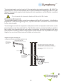
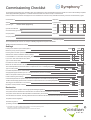
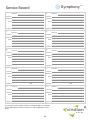
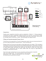
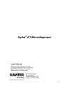
Symphony
TM
Installation
Maintenance
V5 , V5 P, V5 E
Dual Coil Hot Water Cylinder
Solar Electric Cylinder
v1.2
80011
viridian
solar
R
Symphony
Leave this booklet with the
customer for future reference.
2
Hot Outlet
3
Secondary
Return
7
12
Upper
Coil
m
a
b
5
6
c
Cold
Main
8
Balanced
Cold
Connection
Flow
Return
*
11
omit for
drainback
solar systems
TM
1
9
Solar
Discharge Pipe
from Tundish
(See section 2.8)
10
Solar
m
*
*
Drain via
cold inlet
12
components must be positioned
* These
away from electrical devices
3 Inlet Control Set
Incoming Cold
Mains
c
Balanced Cold
Take-off
Upper coil Twin Coil Models only
(V and V P type)
See page 13 for Pre-plumbed cylinder
connections.
b
a
To Tundish
Expansion
Vessel Connection
(remove nut)
To Cylinder
1
viridian
solar
R
Symphony
TM
Installation Kit
No.
1
Twin Coil
Description
V
V
P
Solar Electric
V
E
Tundish
2
Expansion Vessel
3
Inlet Control Set:
a Expansion relief valve
b Check valve
c Pressure reducing valve with strainer
5
Temperature and pressure relief valve
6
Temperature Sensor Pocket
7
High Limit Thermostat (for solar)
8
Dual Thermostat (for boiler)
9
Electrical Immersion Heater
10
Sensor Pocket (solar controller)
11
Upper Electrical Immersion Heater
12
2 Port Motorised Valve
13
Wiring Centre
x2
x1
1.0 Introduction
The Symphony range of unvented twin coil and solar electric cylinders has been designed by
experts in solar technology at Viridian Solar to ensure that the solar energy and auxilliary heat
source work together in harmony. A generous solar-dedicated volume results in optimised solar
energy gains. It is made from corrosion resistant Duplex Stainless Steel, highly insulated with
environmentally friendly foam and enclosed in a smart steel casing.
To help ensure compliance with the relevant Water and Building Regulations all units are
supplied complete with safety and control devices to connect to the cold water main.
Pre-adjusted, high quality controls ensure high flowrate performance.
Symphony is approved to demonstrate compliance with Water Regulations and Building
Regulations G3 & Part L.
1.1 Storage Before Installation
The cylinder should be stored upright in a dry area and kept in its original packaging.
viridian
solar
2
R
Symphony
TM
1.2 Installation
This cylinder should only be installed by a competent person holding a G3 unvented
qualification. The installation of this product is notifiable under the national building regulations.
Leave this booklet with the customer for future reference.
1.3 Water Supply
Symphony Cylinders are capable of delivering over 50 litres per minute, however the flow rate
will be influenced by the water supply. A minimum of 1.5 bar at 20 l/m flow should be available
from the main, which should be tested to ensure it can meet these requirements. It is important
that site pressure readings are taken under dynamic flow conditions; high pressure at zero flow
is not necessarily indicative of satisfactory performance. If necessary consult the local water
supplier.
A minimum of 22mm supply pipe-work is recommended and existing 15mm cold mains
pipe-work may need to be upgraded. Where mains inlet pressures are likely to exceed 16 bar
then an additional pressure reducing device should be fitted upstream.
In areas where Calcuim Carbonate content is greater than 200ppm the cylinder temperature
should be set no higher than 60°C and hard water treatment should be considered
1.4 Location
It is recommended that the cyinder is located within the heated part of the building. If this is not
possible then frost protection is required and additional insulation to pipes and cylinder should
be provided.
Install the cylinder on a flat base capable of supporting its weight when full. The minimum
recommended cupboard size is at least 650mm square. Position to provide access to the valves
for maintenance, remembering that immersion heaters require a space of 375mm for removal.
2. Installation
Each potable and primary water connection on the cylinder is 22mm compression with gland
nut and olive supplied. These connections are designed to accept Table X Copper Tube only.
2.1 Cold Main
Run the cold main to the cylinder and fit an isolating valve (4). A 22mm quarter turn full bore
valve is recommended. Do not use “screwdriver slot” or similar valves. Make the connection to
the cold feed of the cylinder and fit a drain valve. Install the cold inlet set (3) just above the
Temperature & Pressure Relief Valve - TPRV (5) so the cylinder does not have to be drained for
servicing. Ensure that the arrow points in the direction of the water flow.
Select a suitable position for the expansion vessel (2). Mount it to the wall using the bracket
provided. Use the hose to connect to the cold inlet set.
Do not install any isolation valve between
cylinder and safety valves
viridian
solar
3
R
Symphony
TM
2.2 Balanced Cold Connection
There is a 22mm balanced connection on the cold inlet set for outlets that require a balanced
supply. Do not use monobloc mixer tap or showers without a balanced cold connection as this will
back pressurise the cylinder and result in discharge.
2.3 Hot Water Pipework
Run the first part of the hot water distribution pipework in 22mm, reducing as appropriate to the
outlet. Aim to reduce the volume of the hot draw off pipework to a practical minimum to give a fast
hot water response.
2.4 Upper Coil (Twin Coil only)
Compression connections are provided for the primary circuit, which must be positively pumped.
Primary flow and return connections are interchangeable.
Both sealed or vented primary circuits can be used up to a maximum pressure of 7 bar. The
primary heat source must be under thermostatic control. Uncontrolled heat sources for example
back boilers and solid fuel stoves are not suitable. A two port zone valve (supplied) should be fitted
into the primary flow pipework and wired via the dual control and high limit thermostat (6).
All hot pipes must be insulated to at least 1m from the cylinder or until they become concealed.
2.5 Solar Coil
The lower coil is connected to the solar heat source. The solar controller must be wired through
the high limit thermostat (7) to cut off solar energy input in the event of cylinder over-temperature.
Pressurised (fully-filled) solar systems (V250, V260, V270) should also be fitted with a normally
closed two port motorised valve (supplied), energised from the high limit thermostat. A two port
valve must not be fitted when using a drain-back solar system (V200).
Insert the solar cylinder sensor into the lower sensor pocket (10).
2.6 Secondary Circulation
Where secondary circulation is required a pump suitable for potable water should be used in
conjunction with a non return valve to prevent backflow. It may be necessary to incorporate an
extra expansion vessel into the circuit to accommodate the increased system water volume in
larger secondary circulation systems. A secondary return boss is fitted as standard on all models.
2.7 Immersion Heater(s)
Each 3kW immersion heater is fitted with a thermal cut-out in addition to the normal control
thermostat. To help ensure correct replacement the immersion heaters have a special 1 3/4“
thread. Do not replace this component with an immersion heater without a thermal cut-out.
The ‘O’ring on the head of the immersion heater should be correctly positioned and lubricated
before fitting . Screw in hand-tight then gently tighten.
viridian
solar
4
R
Symphony
TM
The electrical supply must be fused at 13A via a double pole isolating switch to BS 3456. The
cable must be 2.5 sq.mm heat resistant (85°C HOFR) sheathed flex complying to BS 6141:1981
Table 8. The electricity supply should comply with local regulations, and be fitted by a qualified
Part P electrician.
Do not operate the immersion heater until the unit is full of water.
2.8 Discharge Arrangement
The discharge pipework must be routed in accordance with Part G3 of schedule 1 of the Building
Regulations. (www.planningportal.gov.uk). Cylinder relief valve connections must not be used
for any other purpose.
The discharge from both the temperature and pressure relief and expansion relief valves can be
joined together via a 15mm end feed Tee. The Tundish must be mounted vertically in a position
that is away from electrical devices and visible to occupants. It must be located in the same
space as the unvented hot water storage system and be fitted as close as possible with a pipe
length of no more than 600mm between tundish and valve outlet.
Diagram of a typical discharge pipe
arrangement (extract from Building Regulation G3)
Safety Device
(e.g. temperature
relief valve)
Metal discharge pipe from
temperature relief valve to tundish
600mm
Note: the discharge will consist of scalding water
and steam. Asphalt, roofing felt and non-metallic
rainwater goods may be damaged by such discharges.
max
Tundish
Note: It is not acceptable to discharge straight
into a soil pipe
300mm min
Metal discharge pipe
from tundish with
continuous fall
Discharge below
fixed grating
Trapped Gulley
viridian
solar
5
R
Symphony
TM
The discharge pipe from the tundish should terminate in a safe place where there is no risk to
persons in the vicinity of the discharge, be of metal and:
a) Be at least one pipe size larger than the nominal outlet size of the safety device unless its total
equivalent hydraulic resistance exceeds that of a straight pipe 9m long i.e. discharge pipes
between 9m and 18m equivalent resistance length should be at least two sizes larger than the
nominal outlet size of the safety device, between 18 and 27m at least 3 sizes larger, and so on.
Bends must be taken into account in calculating the flow resistance.
An alternative approach for sizing discharge pipes would be to follow BS6700 Specification for
design installation, testing and maintenance of services supplying water for domestic use within
buildings and their curtilages.b) Have a vertical section of pipe at least 300mm long, below the
tundish before any elbows or bends in the pipework.
c) Be installed with a continuous fall.
d) It is preferable for the discharge to be visible at both the tundish and the final point of
discharge but where this is not possible or practically difficult there should be clear visibility at
one or other of these locations.
Examples of acceptable discharge arrangements are:
i. Ideally below the fixed grating and above the water seal in a trapped gulley.
ii. Downward discharges at a low level; i.e. up to 100mm above external surfaces such as
car parks, hard standings, grassed areas etc. are acceptable providing that where children
play or otherwise come into contact with discharges, a wire cage or similar guard is
positioned to prevent contact whilst maintaining visibility.
iii. Discharges at a high level; e.g. in to metal hopper and metal down pipe with the end of
the discharge pipe clearly visible (tundish visible or not) or onto a roof capable of withstanding high temperature discharges of water and 3m from any plastic guttering systems that
would collect such discharges (tundish available).
iv. Where a single pipe serves a number of discharges, such as in blocks of flats, the
number served should be limited to not more than 6 systems so that any installation can be
traced reasonably easily. The single common discharge pipe should be at least one pipe
size larger than the largest individual discharge pipe to be connected. If unvented hot water
storage systems are installed where discharges from safety devices may not be apparent
i.e. in dwellings occupied by blind, infirm or disabled people, consideration should be given
to the installation of an electronically operated device to warn when discharge takes place.
viridian
solar
6
R
Symphony
TM
2.9 Wiring Diagrams
2 x 2 Port Zone Valves (S Plan)
Boiler Control
2 Port (Heating)
Br
G
Bl
1
2
O
2 Port (DHW)
Dualstat
G/Y
3
C
E
2
1
C
E
2
1
Br
G
Bl
1
2
O
G/Y
3
Hi Limit
Wiring Centre
1
2
3
4
5
6
7
8
9 10
1
2
3
4
5
6
7
8
9 10
L
N
E
L
N
E
N
1
2
3
E
HTG DHW DHW
ON
ON
OFF
SL
Programmer
Room Stat
L
N
L
E
E
3
N
2
Heating
Pump
Boiler
3 Port + 2 Port Valves (Y Plan)
Boiler Control
3 Port Mid-position
W
G
Bl
O
2
2 Port (DHW)
Dualstat
G/Y
3
C
E
2
1
C
E
2
1
Br
G
Bl
1
2
O
G/Y
3
Hi Limit
Wiring Centre
1
2
3
4
5
6
7
8
9 10
1
2
3
4
5
6
7
8
9 10
L
N
E
L
N
E
N
1
2
3
E
Programmer
Room Stat
L
Br
W
Bl
Live
Brown
White
Black
N
B
O
C
Neutral
Blue
Orange
Common
HTG DHW DHW
ON
ON
OFF
E
G/Y
G
SL
Earth
Green/Yellow
Grey
Switched Live
See page 14 for pre-plumbed cylinder wiring.
7
SL
L
N
Boiler
E
L
E
3
N
2
Heating
Pump
viridian
solar
R
Symphony
TM
Solar Wiring
Solar Hi Limit Stat
C
E
2
Valve not required
for V200
Drainback solar controller
2 Port (Solar)
1
G
Br
O
Bl
G/Y
2
Wiring Centre
(not supplied)
Switched Fused Spur
3
1
2
3
4
5
6
7
8
9 10
1
2
3
4
5
6
7
8
9 10
L
N
E
Br
2
3
B
G/Y
Solar Controller
3.0 Commissioning and Servicing
3.1 Filling
Check all connections for water-tightness including any factory made connections. Prior to
filling the cyinder, the pressure in the expansion vessel should be checked to ensure it is 3 bar.
The hot tap furthest away from the cylinder should be opened before filling the system to let air
out.
The system should be flushed before use. The remaining taps should be opened in turn to
expel air.
3.2 Heating Circuits
Ensure the lever on the two port valve is set to the filling position and use the boiler manufacturers commissioning instructions to fill the primary circuit. When full release the lever. Switch the
programmer to Domestic Hot water (DHW) and allow the unit to start to heat.
Follow the solar commissioning instructions for the solar circuit.
3.3 Storage Temperature
Adjust the dial of the dual thermostat (twin coil) or immersion heater setting to between 55°C
and 65°C as required. A storage temperature of 60-65°C is normal. In many healthcare
applications the guidance on Legionella control and safe water delivery temperatures will
require storing the water at 60-65°C, distributing at 50-55°C and using thermostatic mixing
valves to control the final temperature.
viridian
solar
8
R
Symphony
TM
3.4 Safety Valve Checks
Any water coming from either the expansion relief valve or the temperature / pressure relief
valve during heat up is indicative of a problem.
The temperature relief and expansion relief valves should be fully opened, one at a time then
both together allowing as much water as possible to flow through the tundish. Check that the
discharge pipework is carrying the water away without spillage over the tundish. Release the
valves and check that they reseat properly.
Never bypass safety devices or operate the unit without them fully operational.
3.5 Draining
Isolate from the electrical supply to prevent damage to the immersion heaters. Isolate the unit
from the cold mains. Open the hot tap closest to the unit and syphon from the draining tap with
a hose.
Water may be very hot.
3.6 Annual Servicing
A competent installer should carry out the following checks on an annual basis:
1) The expansion relief valve on the cold inlet set should be eased open allowing water to flow
for 5 seconds. The valve should then be closed making sure it reseats correctly. Repeat this
procedure with the pressure and temperature relief valve. Ensure that the discharge pipework
is allowing the water to drain away.
Water may be very hot.
2) Ensure that any immersion heater is working correctly and that is controlling the water at a
temperature of between 55°C and 65°C.
3) Make sure the gas side in the expansion vessel is charged to 3 bar. Turn off the water supply
to the unit and open a hot tap first. Air or CO2 can be used to repressurise the expansion
vessel.
4) Remove the head on the cold inlet set by unscrewing, and clean the mesh filter within.
5) The service record supplied within this manual should be updated at each service.
The Guarantee may be void without proof of annual servicing and a completed
installation checklist.
viridian
solar
9
R
Symphony
TM
4.0 Warranty
The Symphony cylinder carries a 25 year guarantee for the stainless steel vessel against faulty
materials or manufacture provided that:
• It has been installed by a competent person according to the prevailing standards,
regulations and this installation guide.
• It has not been modified, misused, tampered with or subjected to neglect.
• It has only been used for the storage of potable water.
• It has not been subjected to frost damage.
• The completed service record confirms an annual service by a competent person.
• The system is fed from a public water supply.
The guarantee period starts from the date of purchase and no registration is required. The
guarantee is not transferable, and rests with the original householder.
Please note that invoices for servicing may be required to confirm the service record. All the
components supplied with the cylinder carry a 2 year guarantee.
Exclusions - The Guarantee does not Cover:
The effects of scale build up. Any labour charges associated with replacing the unit or its parts.
Any consequential losses caused by the failure or malfunction of the unit.
In the Event of a Problem
If you have a problem in the first year contact the plumber who fitted the unit. Thereafter
contact the plumber who carries out the annual servicing.
5.0 User Instructions
Your hot water cylinder is automatic in normal use and requires only annual servicing. You
should employ an competent person to perform annual servicing.
The immersion heater is provided as a means of back up heating, and should not be used at
the same time as the primary heat source.
For advice on how to get the most from your solar heating equipment, refer to the Clearline
User Manual.
If water is flowing through the safety valves and into the tundish this indicates a
fault condition. If this water is hot turn off the boiler, solar system and immersion
heater. Do not turn off the water until the cylinder cools. Call a plumber.
viridian
solar
10
R
Symphony
Commissioning Checklist
TM
The Commissioning Checklist is to be completed in full by the competent person who commissioned the Symphony cylinder as a means of demonstrating compliance
with the appropriate Building Regulations. This booklet should be handed to the customer to keep for future reference.
Failure to install and commission this equipment to the manufacturer’s instructions may invalidate the warranty, but does not affect statutory rights.
Customer Name
Telephone
Cylinder Model
Address
Viridian Solar Symphony
V515
V518
V521
V525
V530
V515E
V518E
V521E
V525E
V530E
Commissioned by (print name)
V515P
V518P
V521P
V525P
V530P
Company Name
Telephone
Cylinder Type
Cylinder Serial Number
Company Address
Commissioning Date
To be completed by the customer on receipt of a Building Regulatinos Compliance Certificate*
Building Regulations Notification Number
Settings
Sealed
Open
Strainer been cleared of installation debris (if fitted)?
Yes
No
Is the installation in a hard water area (CaCO3 above 200ppm)?
Yes
No
If yes, has a water scale reducer been fitted?
Yes
No
Primary circuit sealed or open vented system?
°C
Maximum primary flow temperature?
Incoming static cold water pressure at the inlet to the system?
bar
Type of scale reducer fitted?
°C
Hot water thermostat set temperature?
l/min
Maximum hot water flow rate at set thermostat temperature (measured at high flow outlet)?
Yes
Time and temperature controls been fitted in compliance with Part L of Building Regulations?
Y Plan
Type of control system
S Plan
Other
°C
Hot water temperature at the nearest outlet?
Yes
All appropriate pipes insulated up to 1m or the point where they become concealed?
Where is the pressure reducing valve situated?
bar
Pressure reducing valve setting?
Yes
Combined temperature and pressure relief valve and expansion valve fitted and discharge tested?
No
Yes
Tundish and discharge pipework been connected and terminated to Part G of Building Regulations?
All energy sources fitted with a cut out device?
Yes
No
Expansion vessel pressure checked?
Yes
No
Declaration
The hot water system complies with the appropriate Building Regulations
Yes
The system has been installed and commissioned in accordance with the manufacturer’s instructions
Yes
The system controls have been demonstrated and understood by the customer
Yes
The manufacturer’s literature, including Checklist and Service Record has been explained and left with the customer
Yes
Competent Person’s Signature
Customer’s Signature
(Confirming satisfactory demonstration and receipt of manufacturer’s literature)
* All installations in England and Wales must be notified to a Local Authority Building Control
viridian
solar
either directly or through a Competent Persons Scheme.
A Building Regulations Compliance Certificate will then be issued to the customer.
11
R
Symphony
Service Record
1
2
Technician
Technician
Company
Company
Telephone
Telephone
Notes
Notes
Date
Signature
3
Date
Signature
4
Technician
Technician
Company
Company
Telephone
Telephone
Notes
Notes
Date
Signature
5
Date
Signature
6
Technician
Technician
Company
Company
Telephone
Telephone
Notes
Notes
Signature
7
Date
Signature
8
Technician
Company
Telephone
Telephone
Notes
Notes
Signature
Date
Signature
10
Technician
Company
Telephone
Telephone
Notes
Notes
Date
Signature
Your Symphony solar cylinder should be serviced annually by a competent
person following the procedure in Section 3.7 and completing the record
above.
12
Date
Technician
Company
Signature
Date
Technician
Company
9
TM
Date
viridian
solar
R
Symphony
Pre-plumbed Cylinder
2
Hot Outlet
Secondary
Return
3
19
Heating Zone 2
m
12
a
c
b
8
12
Balanced
Cold
Connection
12 16
Space
Heating
Return
1
18
Return
to Boiler
*
15
13
9
Discharge Pipe
from Tundish
(See section 2.8)
14
omit for
drainback
solar systems
Solar
Flow
From
Boiler
10
Solar
*
m
17
12
*
components
* These
must be positioned
away from electrical
devices
Drain via
cold inlet
Primary Filling Loop (disconnect)
Pre-plumbed Components
15
1
Tundish
16
Auto By-pass Valve
3
Inlet Control Set:
17
Drain Cock (cold feed)
a Expansion relief valve
18
Drain Cock (primary loop)
b Check valve
19
Auto Air Vent
c Pressure reducing valve with strainer
No.
5
Cold
Main
5
m
Heating Zone 1
6
7
m
No.
TM
Temperature and pressure relief valve
Loose Components
2
Expansion Vessel (potable water)
6
Temperature Sensor Pocket
7
High Limit Thermostat (solar)
8
Dual Thermostat (for boiler)
12
2 Port Motorised Valve
9
Electrical Immersion Heater
Expansion Vessel (primary loop)
10
Sensor Pocket (solar controller)
3 bar Pressure Relief Valve
11
Upper Electrical Immersion Heater
Pressure Gauge
12
2 Port Motorised Valve
Primary Manifold
13
Wiring Centre
3 Channel Programmer
14
Primary Circulating Pump
Room Thermostat
viridian
solar
13
R
Symphony
Programmer
HW CH 1
ON ON
N
L
1
2
3
4
Zone 1
Thermostat
CH2
ON
5
Zone 2
Thermostat
2
4
6
1
TM
2
4
3
1
Pre-wired plugs
3
Black
Pump
Green
Dual Stat
Boiler
E
Mains Isolator
Blue
HW Actuator
N
Red
CH Actuator
L
E
N
P/L
L
Boiler
permanent
live if required
1
2
3
4
5
6
7
8
9
10
Diagram Showing
On Site Wiring
Wiring Centre - this side pre-wired
Connections
Potable water connections should be made as described in Section 2. Primary pipework
connections are 22mm compression fittings with gland nut and olive, and should be made
according to the drawing above. The circulating pump comes with a transit pipe, which should
be removed before a connection is made. Wire according to the diagram above.
Filling and Commissioning the Primary Circuit
Fill and flush in the usual manner. Ensure all drain points and air valve are closed and that the 2
port valve and pump isolation valves are open. Fill via the filling loop.
Release all air from the auto-air valve and any other high points in the system. Fill to a pressure
according to the requirements of both boiler and radiator manufacturers. During filling, check that
all plumbing connections (including factory-made) are fully water tight. Whilst every care is taken
to ensure factory-made connections are water tight, the effects of transit may cause some
connections to subsequently leak, for which Viridian Solar can accept no responsibility for
damage or inconvenience caused.
Once full of water and devoid of air, turn on the boiler and thermostats to heat both
water and heating circuits. The recommended hot water storage
temperature is 60C. Adjust the auto by-pass valve according to
the manufacturers instructions (included).
viridian
solar
14
R
Symphony
TM
Specification
V515
V518
V521
V525
V530
Size
litres
150
180
210
250
300
Dedicated Solar Volume (Vs)
litres
75
90
105
110
125
Primary Heated Volume (Vb)
litres
75
90
105
140
175
Heat Loss (whole cylinder)
kWh/24h
1.41
1.53
1.80
2.15
2.28
Heat upTime (upper coil)
minutes
12.0
15.5
19.0
23.0
29.0
Reheat Time (upper coil)
minutes
9.4
12.1
14.8
18.5
24.1
Heat upTime (electric cylinder)
minutes
85
93
119
160
199
Weight (empty)
kg
40
45
48
53
63
Weight (full)
kg
190
225
258
303
363
Height
mm
1,102
1,290
1,478
1,782
2,041
Diameter
mm
545
545
545
545
545
Solar Coil Volume
litres
2.0
2.6
3.6
3.8
3.8
Solar Coil Surface Area
m2
0.41
0.54
0.76
0.79
0.79
Primary Coil Rating
kW
16.7
15.8
14.9
14.6
17.9
Maximum Water Supply Pressure
bar
16
Maximum Coil Pressure
bar
3
Operating pressure
bar
3
Expansion Valve Setting
bar
T&P Valve Setting
°C/bar
Expansion Vessel Charge
bar
Immersion Heater Rating
kW
Immersion Heater Length
mm
Global Warming Potential
CO2 equiv
Model
6
90/7
3
3
350 (twin coil) 400 (electric)
Viridian Solar
Atlas Building, Stirling Way
Papworth, Cambridge. CB23 3GY
T 01480 831 501 F 01480 831 831
www.viridiansolar.co.uk
V515, V518, V521, V525, V530
viridian
solar
Dual Coil Hot Water Cylinder
v1.0
800011A
R
1
Zero
Ozone Depletion Potential