1
Mitsubishi Industrial Robot
RV-4F/7F/13F/20F Series
INSTRUCTION MANUAL
ROBOT ARM SETUP & MAINTENANCE
BFP-A8935-E
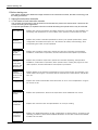
Safety Precautions
Always read the following precautions and the separate "Safety
Manual" before starting use of the robot to learn the required
measures to be taken.
CAUTION
CAUTION
WARNING
CAUTION
WARNING
CAUTION
CAUTION
CAUTION
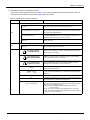
All teaching work must be carried out by an operator who has received special
training. (This also applies to maintenance work with the power source turned
ON.)
Enforcement of safety training
For teaching work, prepare a work plan related to the methods and procedures
of operating the robot, and to the measures to be taken when an error occurs
or when restarting. Carry out work following this plan. (This also applies to
maintenance work with the power source turned ON.)
Preparation of work plan
Prepare a device that allows operation to be stopped immediately during
teaching work. (This also applies to maintenance work with the power source
turned ON.)
Setting of emergency stop switch
During teaching work, place a sign indicating that teaching work is in progress
on the start switch, etc. (This also applies to maintenance work with the power
source turned ON.)
Indication of teaching work in progress
Provide a fence or enclosure during operation to prevent contact of the
operator and robot.
Installation of safety fence
Establish a set signaling method to the related operators for starting work, and
follow this method.
Signaling of operation start
As a principle turn the power OFF during maintenance work. Place a sign
indicating that maintenance work is in progress on the start switch, etc.
Indication of maintenance work in progress
Before starting work, inspect the robot, emergency stop switch and other
related devices, etc., and confirm that there are no errors.
Inspection before starting work
The points of the precautions given in the separate "Safety Manual" are given below.
Refer to the actual "Safety Manual" for details.
CAUTION
CAUTION
CAUTION
CAUTION
CAUTION
CAUTION
WARNING
WARNING
CAUTION
WARNING
CAUTION
CAUTION
CAUTION
CAUTION
WARNING
Use the robot within the environment given in the specifications. Failure to do
so could lead to a drop or reliability or faults. (Temperature, humidity,
atmosphere, noise environment, etc.)
Transport the robot with the designated transportation posture. Transporting
the robot in a non-designated posture could lead to personal injuries or faults
from dropping.
Always use the robot installed on a secure table. Use in an instable posture
could lead to positional deviation and vibration.
Wire the cable as far away from noise sources as possible. If placed near a noise
source, positional deviation or malfunction could occur.
Do not apply excessive force on the connector or excessively bend the cable.
Failure to observe this could lead to contact defects or wire breakage.
Make sure that the workpiece weight, including the hand, does not exceed the
rated load or tolerable torque. Exceeding these values could lead to alarms or
faults.
Securely install the hand and tool, and securely grasp the workpiece. Failure to
observe this could lead to personal injuries or damage if the object comes off or
flies off during operation.
Securely ground the robot and controller. Failure to observe this could lead to
malfunctioning by noise or to electric shock accidents.
Indicate the operation state during robot operation. Failure to indicate the state
could lead to operators approaching the robot or to incorrect operation.
When carrying out teaching work in the robot's movement range, always secure
the priority right for the robot control. Failure to observe this could lead to
personal injuries or damage if the robot is started with external commands.
Keep the jog speed as low as possible, and always watch the robot. Failure to do
so could lead to interference with the workpiece or peripheral devices.
After editing the program, always confirm the operation with step operation
before starting automatic operation. Failure to do so could lead to interference
with peripheral devices because of programming mistakes, etc.
Make sure that if the safety fence entrance door is opened during automatic
operation, the door is locked or that the robot will automatically stop. Failure to
do so could lead to personal injuries.
Never carry out modifications based on personal judgments, or use nondesignated maintenance parts.
Failure to observe this could lead to faults or failures.
When the robot arm has to be moved by hand from an external area, do not
place hands or fingers in the openings. Failure to observe this could lead to
hands or fingers catching depending on the posture.
CAUTION
CAUTION
CAUTION
Do not stop the robot or apply emergency stop by turning the robot controller's
main power OFF. If the robot controller main power is turned OFF during
automatic operation, the robot accuracy could be adversely affected. Moreover,
it may interfere with the peripheral device by drop or move by inertia of the arm.
Do not turn off the main power to the robot controller while rewriting the
internal information of the robot controller such as the program or parameters.
If the main power to the robot controller is turned off while in automatic
operation or rewriting the program or parameters, the internal information of the
robot controller may be damaged.
Use the network equipments (personal computer, USB hub, LAN hub, etc)
confirmed by manufacturer. The thing unsuitable for the FA environment
(related with conformity, temperature or noise) exists in the equipments
connected to USB. When using network equipment, measures against the noise,
such as measures against EMI and the addition of the ferrite core, may be
necessary. Please fully confirm the operation by customer. Guarantee and
maintenance of the equipment on the market (usual office automation
equipment) cannot be performed.
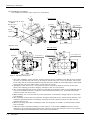
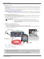
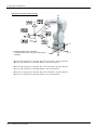
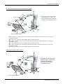
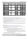
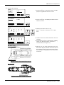
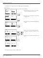
*CR751-D or CR751-Q controller
Notes of the basic component are shown.
CAUTION
Please install the earth leakage breaker in the primary side supply power supply
of the controller of CR751-D or CR751-Q because of leakage protection.
AC200V
Earth
leakage breaker
漏電遮断器
(NV)
CR751-D
controller/CR751-Q drive unit
CR751コントローラ(前面)
Cover
端子カバー
Cover
端子カバー
Grounding
アース接続ネジ
screw
Grounding
terminal
保護アース端子
(PE)
(PE)
Connector
コネクタ
Revision history
Date of Point
Instruction Manual No.
Revision Details
2012-09-27
BFP-A8935
・ First print
2012-10-03
BFP-A8935-A
・ The notes about installation of the controller and the robot arm were added. (neither
direct rays nor the heat of lighting)
・ Cross-reference places, in the Inspection, maintenance and replacement of timing belt
etc, were corrected. (Error in writing)
・ Fixing screws of the Cable clamp box, No.1 arm cover U, CONBOX cover and CONBOX
cover R were corrected. (formerly M4x12)
・ Seal washers of screws which fixes cable clamp box and CONBOX cover R were
corrected to attachment only at protection specification.
2012-11-20
BFP-A8935-B
・ The lithium battery type was added to "Table 5-6: Consumable part list".
・ The statement about trademark registration was added.
2013-01-09
BFP-A8935-C
・ The grease nipple of attachments was corrected. (table of Standard configuration and
Lubrication specifications)
・ The quantity of screw for suspension fittings was changed.
・ J1 axis operating range change (option) was added.
・ The precautions to hand input cable installation were added.
・ The couplings were added to “Table 2-1: Standard configuration”
・ The grounding method to the Base external wiring set was added.
2013-03-21
BFP-A8935-D
・ The description of RV-7FLL, RV-13F and RV-20F were added.
2013-04-04
BFP-A8935-E
・ The installation method of the optional solenoid valve set (1F-VD0*-03/1F-VD0*E-03)
was corrected.
*Introduction
Thank you for purchasing the Mitsubishi industrial robot.
This instruction manual explains the method of unpacking, installation and maintenance and inspection of
the robot arm.
Always read through this manual before starting use to ensure correct usage of the robot.
The information contained in this document has been written to be accurate as much as possible. Please
interpret that items not described in this document "cannot be performed."
This document explains for the following robot type.
Robot type
・ RV-4F/4FL series ................ Note) Indicates it as RV-4F series.
・ RV-7F/7FL series ................ Note) Indicates it as RV-4F series.
・ RV-7FLL *1)
・ RV-13F/13FL series *1)
・ RV-20F series *1)
*1) Indicates it as "RV-13F series" for a general name of these robots.
・ No part of this manual may be reproduced by any means or in any form, without prior consent from
Mitsubishi.
・ The details of this manual are subject to change without notice.
・ The information contained in this document has been written to be accurate as much as possible.
Please interpret that items not described in this document "cannot be performed." or "alarm may
occur".
Please contact your nearest dealer if you find any doubtful, wrong or skipped point.
・ This specifications is original.
・ Company names and production names in this document are the trademarks or registered trademarks
of their respective owners.
Copyright(C) 2012-2013 MITSUBISHI ELECTRIC CORPORATION
CONTENTS
Page
1 Before starting use ..........................................................................................................................
1.1 Using the instruction manuals ...................................................................................................
1.1.1 The details of each instruction manuals ...............................................................................
1.1.2 Symbols used in instruction manual ....................................................................................
1.2 Safety Precautions ....................................................................................................................
1.2.1 Precautions given in the separate Safety Manual ................................................................
1-1
1-1
1-1
1-2
1-3
1-4
2 Unpacking to Installation .............................................................................................................................................................. 2-6
2.1 Confirming the product ......................................................................................................................................................... 2-6
2.2 Installation .................................................................................................................................................................................. 2-8
2.2.1 Unpacking ............................................................................................................................................................................ 2-8
2.2.2 Transportation procedures (Transporting with a crane) ................................................................................. 2-9
2.2.3 Installation procedures ................................................................................................................................................ 2-11
2.2.4 Grounding procedures .................................................................................................................................................. 2-13
(1) Grounding methods ................................................................................................................................................... 2-13
(2) Grounding procedures ............................................................................................................................................. 2-13
2.2.5 Connecting with the controller ................................................................................................................................ 2-14
(1) CR750 controller ....................................................................................................................................................... 2-14
(2) CR751 controller ....................................................................................................................................................... 2-16
2.2.6 About oil mist specification ....................................................................................................................................... 2-18
(1) Piping for pressurization inside robot arm ...................................................................................................... 2-18
2.2.7 About clean specification ........................................................................................................................................... 2-18
(1) Piping for suction inside robot arm .................................................................................................................... 2-18
2.3 Setting the origin ................................................................................................................................................................... 2-19
2.3.1 Installing the teaching pendant (T/B) ................................................................................................................... 2-19
(1) Installing the T/B (CR750 controller) ............................................................................................................... 2-19
(2) Installing the T/B (CR751 controller) ............................................................................................................... 2-20
2.3.2 Setting the origin with the origin data input method ...................................................................................... 2-21
(1) Confirming the origin data ..................................................................................................................................... 2-21
(2) Turning ON the control power ............................................................................................................................. 2-21
(3) Preparing the T/B ..................................................................................................................................................... 2-22
(4) Selecting the origin setting method ................................................................................................................... 2-23
(5) Inputting the origin data ......................................................................................................................................... 2-24
(6) Installing the CONBOX cover. ............................................................................................................................. 2-25
2.4 Confirming the operation .................................................................................................................................................... 2-26
(1) JOINT jog operation ................................................................................................................................................. 2-30
(2) XYZ jog operation ...................................................................................................................................................... 2-32
(3) TOOL jog operation .................................................................................................................................................. 2-34
(4) 3-axis XYZ jog operation ....................................................................................................................................... 2-36
(5) CYLNDER jog operation ......................................................................................................................................... 2-38
(6) Work jog operation ......................................................................................................... 2-40
3 Installing the option devices .....................................................................................................................................................
3.1 Installing the J1 axis operating range change ...........................................................................................................
3.1.1 RV-4F/7F series (RV-4F : 1F-DH-03、 RV-7F : 1F-DH-04) ..................................................................
(1) Configuration ...............................................................................................................................................................
(2) Changeable angle .......................................................................................................................................................
(3) Installation procedure ..............................................................................................................................................
(4) Setting the parameter .............................................................................................................................................
(5) Check the operating range ....................................................................................................................................
3.1.2 RV-13F series (1F-DH-05J1) ..................................................................................................................................
(1) Configuration ...............................................................................................................................................................
(2) Changeable ...................................................................................................................................................................
(3) Installation procedure ..............................................................................................................................................
(4) Setting the parameter .............................................................................................................................................
(5) Check the operating range ....................................................................................................................................
3.2 Installing the solenoid valve set ......................................................................................................................................
i
3-46
3-46
3-46
3-46
3-47
3-49
3-50
3-50
3-51
3-51
3-52
3-53
3-55
3-55
3-56
CONTENTS
Page
3.3 Installing the hand input cable .........................................................................................................................................
3.4 Installing the hand output cable ......................................................................................................................................
3.5 Installing the Forearm external wiring set/ Base external wiring set .............................................................
(1) Installing the Forearm external wiring set .......................................................................................................
(2) Installing the Base external wiring set .............................................................................................................
3-61
3-63
3-66
3-66
3-67
4 Basic operations ............................................................................................................................................................................ 4-69
5 Maintenance and Inspection ..................................................................................................................................................... 5-70
5.1 Maintenance and inspection interval ............................................................................................................................. 5-70
5.2 Inspection items ..................................................................................................................................................................... 5-71
5.2.1 Daily inspection items .................................................................................................................................................. 5-71
5.2.2 Periodic inspection ........................................................................................................................................................ 5-72
5.3 Maintenance and inspection procedures ..................................................................................................................... 5-73
5.3.1 Robot arm structure ..................................................................................................................................................... 5-73
5.3.2 Installing/removing the cover ................................................................................................................................... 5-76
5.3.3 Inspection, maintenance and replacement of timing belt .............................................................................. 5-78
(1) Timing belt replacement period ......................................................................................................................... 5-78
(2) Inspection, maintenance and replacement of J1-axis timing belt (RV-4F/7F series only) ...... 5-79
(3) Inspection, maintenance and replacement of J3-axis timing belt (RV-4F/7F series only) ...... 5-80
(4) Inspection, maintenance and replacement of J4-axis timing belt (For RV-4F/7F series) ........ 5-81
(5) Inspection, maintenance and replacement of J4-axis timing belt (For RV-13F series) ............. 5-82
(6) Inspection, maintenance and replacement of J5 axis timing belt ......................................................... 5-83
(7) Inspection, maintenance and replacement of J6-axis timing belt ........................................................ 5-85
(8) Timing belt tension ................................................................................................................................................... 5-87
5.3.4 Lubrication ........................................................................................................................................................................ 5-88
(1) Lubrication position and specifications ............................................................................................................ 5-88
(2) Lubrication method ................................................................................................................................................... 5-90
5.3.5 Replacing the backup battery ................................................................................................................................... 5-92
(1) Replacing the battery (robot arm) ...................................................................................................................... 5-93
5.4 About Overhaul ...................................................................................................................................................................... 5-95
5.5 Maintenance parts ................................................................................................................................................................. 5-96
5.6 Resetting the origin .............................................................................................................................................................. 5-98
5.6.1 Jig method ........................................................................................................................................................................ 5-99
(1) J1 axis origin setting ............................................................................................................................................. 5-100
(2) J2 axis origin setting ............................................................................................................................................. 5-102
(3) J3 axis origin setting ............................................................................................................................................. 5-105
(4) J4 axis origin setting ........................................................................................................................................... 5-108
(5) Origin setting of J5 axis and J6 axis (jig) ..................................................................................................... 5-110
5.6.2 ABS origin method ..................................................................................................................................................... 5-113
(1) Select the T/B ........................................................................................................................................................ 5-115
5.6.3 User origin method ..................................................................................................................................................... 5-116
5.6.4 Recording the origin data ........................................................................................................................................ 5-118
(1) Confirming the origin data label ........................................................................................................................ 5-118
(2) Confirming the origin data .................................................................................................................................. 5-118
(3) Recording the origin data .................................................................................................................................... 5-118
(4) Installing the cover ................................................................................................................................................ 5-118
6Appendix ............................................................................................................................................................................ Appendix-119
Appendix 1 : Configuration flag .......................................................................................................................... Appendix-119
ii
1Before starting use
1 Before starting use
This chapter explains the details and usage methods of the instruction manuals, the basic terminology and
the safety precautions.
1.1 Using the instruction manuals
1.1.1 The details of each instruction manuals
The contents and purposes of the documents enclosed with this product are shown below. Use these documents according to the application.
For special specifications, a separate instruction manual describing the special section may be enclosed.
Safety Manual
Explains the common precautions and safety measures to be taken for robot handling, system design and manufacture to ensure safety of the operators involved with the robot.
Standard
Specifications
Explains the product's standard specifications, factory-set special specifications, option
configuration and maintenance parts, etc. Precautions for safety and technology, when
incorporating the robot, are also explained.
Robot Arm
Setup &
Maintenance
Controller
Setup, Basic
Operation and
Maintenance
Detailed
Explanation of
Functions and
Operations
Troubleshooting
Additional axis
function
Explains the procedures required to operate the robot arm (unpacking, transportation,
installation, confirmation of operation), and the maintenance and inspection procedures.
Explains the procedures required to operate the controller (unpacking, transportation,
installation, confirmation of operation), basic operation from creating the program to automatic operation, and the maintenance and inspection procedures.
Explains details on the functions and operations such as each function and operation, commands used in the program, connection with the external input/output device, and parameters, etc.
Explains the causes and remedies to be taken when an error occurs. Explanations are given
for each error No.
Explains the specifications, functions and operations of the additional axis control.
Tracking Function Manual
Explains the control function and specifications of conveyor tracking
Extended Function Instruction Manual
Explains the detailed description of data configuration of shared memory, monitoring, and
operating procedures, about the PLC(CR750-Q/CR751-Q controller) and the GOT(CR750D/CR751-D controller).
1-1 Using the instruction manuals
1Before starting use
1.1.2 Symbols used in instruction manual
The symbols and expressions shown in Table 1-1 are used throughout this instruction manual. Learn the
meaning of these symbols before reading this instruction manual.
Table 1-1:Symbols in instruction manual
Terminology
Item/Symbol
Meaning
iQ Platform
Controller
Indicates the controller which controls the robot arm.
It consists of the robot CPU system and the drive unit.
The robot CPU unit or robot CPU
Indicates the CPU unit for the robots which installed to the sequencer
base unit (Q3 □ DB) of MELSEC-Q series. It is connected with the
drive unit by the dedicated cable.
The robot CPU system
Multi-CPU system.
It consists of MELSEC units, such as the sequencer base unit, the
sequencer CPU unit, and the robot CPU unit, etc.
Drive unit
Indicates the box which mounts the servo amplifier for robot, and the
safety circuit, etc.
Item
Stand-alone type
Item
Symbol
Indicates the box which arranged control parts, such as robot CPU,
servo amplifier, and the safety circuit.
Controller
DANGER
WARNING
CAUTION
Precaution indicating cases where there is a risk of operator fatality or
serious injury if handling is mistaken. Always observe these precautions to safely use the robot.
Precaution indicating cases where the operator could be subject to
fatalities or serious injuries if handling is mistaken. Always observe
these precautions to safely use the robot.
Precaution indicating cases where operator could be subject to injury
or physical damage could occur if handling is mistaken. Always
observe these precautions to safely use the robot.
[JOG]
If a word is enclosed in brackets or a box in the text, this refers to a
key on the teaching pendant.
[RESET] + [EXE]
(A)
(B)
This indicates to press the (B) key while holding down the (A) key.
In this example, the [RESET] key is pressed while holding down the
[EXE] key.
T/B
This indicates the teaching pendant.
O/P
Indicates the operating panel on the front of controller or drive unit for
the controller which installed the operating panel
CR751 (Thin type)
CR751 (Heavy type)
There are two kinds of CR751 controller; one is "Thin type" (the
height is 98mm) and the other is "Heavy type" (the height is 174mm),
each of which are different in height.
Thin type: CR751-03HD/Q, CR751-02VD/Q, CR751-04VD/Q,
CR751-07VD/Q.
Heavy type: CR751-13VD/Q, CR751-20VD/Q, CR751-07VLD/Q.
* Refer to separate Standard Specifications Manual for the outside
dimension of CR751 controller.
Using the instruction manuals 1-2
1Before starting use
1.2 Safety Precautions
Always read the following precautions and the separate "Safety Manual" before starting use of the robot to
learn the required measures to be taken.
CAUTION
CAUTION
WARNING
CAUTION
DANGER
CAUTION
CAUTION
CAUTION
1-3 Safety Precautions
All teaching work must be carried out by an operator who has received special
training. (This also applies to maintenance work with the power source turned ON.)
Enforcement of safety training
For teaching work, prepare a work plan related to the methods and procedures of
operating the robot, and to the measures to be taken when an error occurs or when
restarting. Carry out work following this plan. (This also applies to maintenance
work with the power source turned ON.)
Preparation of work plan
Prepare a device that allows operation to be stopped immediately during teaching
work. (This also applies to maintenance work with the power source turned ON.)
Setting of emergency stop switch
During teaching work, place a sign indicating that teaching work is in progress on
the start switch, etc. (This also applies to maintenance work with the power source
turned ON.)
Indication of teaching work in progress
Provide a fence or enclosure during operation to prevent contact of the operator
and robot.
Installation of safety fence
Establish a set signaling method to the related operators for starting work, and follow this method.
Signaling of operation start
As a principle turn the power OFF during maintenance work. Place a sign indicating that maintenance work is in progress on the start switch, etc.
Indication of maintenance work in progress
Before starting work, inspect the robot, emergency stop switch and other related
devices, etc., and confirm that there are no errors.
Inspection before starting work
1Before starting use
1.2.1 Precautions given in the separate Safety Manual
The points of the precautions given in the separate "Safety Manual" are given below.
Refer to the actual "Safety Manual" for details.
DANGER
CAUTION
CAUTION
CAUTION
CAUTION
CAUTION
CAUTION
WARNING
WARNING
CAUTION
WARNING
CAUTION
CAUTION
CAUTION
WARNING
If the automatic operation of the robot is operated by two or more control equipment, design the right management of operation of each equipment of the customer.
Use the robot within the environment given in the specifications. Failure to do so
could lead to a drop or reliability or faults. (Temperature, humidity, atmosphere,
noise environment, etc.)
Transport the robot with the designated transportation posture. Transporting the
robot in a non-designated posture could lead to personal injuries or faults from
dropping.
Always use the robot installed on a secure table. Use in an instable posture could
lead to positional deviation and vibration.
Wire the cable as far away from noise sources as possible. If placed near a noise
source, positional deviation or malfunction could occur.
Do not apply excessive force on the connector or excessively bend the cable.
Failure to observe this could lead to contact defects or wire breakage.
Make sure that the workpiece weight, including the hand, does not exceed the
rated load or tolerable torque. Exceeding these values could lead to alarms or
faults.
Securely install the hand and tool, and securely grasp the workpiece. Failure to
observe this could lead to personal injuries or damage if the object comes off or
flies off during operation.
Securely ground the robot and controller. Failure to observe this could lead to
malfunctioning by noise or to electric shock accidents.
Indicate the operation state during robot operation. Failure to indicate the state
could lead to operators approaching the robot or to incorrect operation.
When carrying out teaching work in the robot's movement range, always secure
the priority right for the robot control. Failure to observe this could lead to personal
injuries or damage if the robot is started with external commands.
Keep the jog speed as low as possible, and always watch the robot. Failure to do
so could lead to interference with the workpiece or peripheral devices.
After editing the program, always confirm the operation with step operation before
starting automatic operation. Failure to do so could lead to interference with
peripheral devices because of programming mistakes, etc.
Make sure that if the safety fence entrance door is opened during automatic operation, the door is locked or that the robot will automatically stop. Failure to do so
could lead to personal injuries.
Never carry out modifications based on personal judgments, or use non-designated maintenance parts.
Failure to observe this could lead to faults or failures.
When the robot arm has to be moved by hand from an external area, do not place
hands or fingers in the openings. Failure to observe this could lead to hands or fingers catching depending on the posture.
Safety Precautions 1-4
1Before starting use
CAUTION
CAUTION
DANGER
DANGER
CAUTION
1-5 Safety Precautions
Do not stop the robot or apply emergency stop by turning the robot controller's
main power OFF.
If the robot controller main power is turned OFF during automatic operation, the
robot accuracy could be adversely affected.
Do not turn off the main power to the robot controller while rewriting the internal
information of the robot controller such as the program or parameters. If the main
power to the robot controller is turned off while in automatic operation or rewriting
the program or parameters, the internal information of the robot controller may be
damaged.
When the SSCNETIII cable is removed, install the cap in the connector.
If the cap is not installed, there is a possibility of malfunctioning by adhesion of the
dust etc.
Don't remove the SSCNETIII cable, when the power supply of the robot controller is
turned on. Don't face squarely the light emitted from the tip of the SSCNETIII connector or the cable. If light strikes the eyes, there is a possibility of feeling the sense
of incongruity for the eyes. (The light source of SSCNETIII is equivalent to the class
1 specified to JIS C 6802 and IEC 60825-1.)
Make sure there are no mistakes in the wiring. Connecting differently to the way
specified in the manual can result in failures, such as the emergency stop not
being released. In order to prevent from occurring, please be sure to check that all
functions (such as the teaching box emergency stop, customer emergency stop,
and door switch) are working properly after the wiring setup is completed
2Unpacking to Installation
2 Unpacking to Installation
2.1 Confirming the product
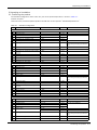
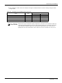
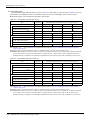
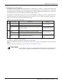
The standard configuration of the robot arm, part of the purchased product, is shown in Table 2-1.
Confirm the parts.
Users who have purchased optional products should refer to the separate "Standard Specifications".
Table 2-1 : Standard configuration
No.
Part name
Type
Qty.
Remarks
RV-4F series
1
Robot arm
2
Guarantee card
RV-4F series
Each 1 unit
3
Installation bolts
M8 x 40
4 pcs.
4
Spring washer for installation bolts
For M8
4 pcs.
5
Plain washer for installation bolts
For M8
4 pcs.
6
Grease nipple
WA-610
7
Coupling
φ4
8
Suspension fitting
9
Suspension fitting installation bolt
1 copy
For robot arm installation
5 pc.
As needed Is needed quantity attachment only to
Internal wiring and piping specification
types.
2 sets
M6 x 20
6 pcs.
10 Plain washer for suspension fitting installa- For M6
tion bolt
6 pcs.
11 Eye bolt
M10
4 pcs.
12 Nut for eye bolt
For M10
4 pcs.
14 Fixing plate installation bolt
M15 x 12
4 pcs.
15 Plain washer for fixing plate
For M5
4 pcs.
13 Fixing plate
1 set
RV-7F series
1
Robot arm
2
Guarantee card
RV-7F series
Each 1 unit
3
Installation bolts
M8 x 40
4 pcs.
4
5
Spring washer for installation bolts
Plain washer for installation bolts
For M8
For M8
4 pcs.
4 pcs.
6
Grease nipple
WA-610
7
Coupling
φ4
8
Suspension fitting
9
Suspension fitting installation bolt
1 copy
4 pcs.
As needed Is needed quantity attachment only to
Internal wiring and piping specification
types.
2 sets
M8 x 25
4 pcs.
10 Plain washer for suspension fitting installa- For M8
tion bolt
4 pcs.
11 Eye bolt
M10
4 pcs.
12 Nut for eye bolt
For M10
4 pcs.
14 Fixing plate installation bolt
M15 x 12
4 pcs.
15 Plain washer for fixing plate
For M5
4 pcs.
13 Fixing plate
RV-13F series
1 Robot arm
1 set
RV-13F series
Each 1 unit
2
Guarantee card
3
Installation bolts
M12 x 55
4 pcs.
4
Spring washer for installation bolts
For M12
4 pcs.
5
Plain washer for installation bolts
For M12
4 pcs.
6
Grease nipple
WA-110
1 copy
3 pcs.
WA-610
7
Coupling
8
Suspension fitting
9
Suspension fitting installation bolt
For robot arm installation
φ4
For robot arm installation
4 pcs.
As needed Is needed quantity attachment only to
Internal wiring and piping specification
types.
2 sets
M10 x 45
4 pcs.
Confirming the product 2-6
2Unpacking to Installation
No.
Part name
Type
Qty.
10 Plain washer for suspension fitting installa- For M10
tion bolt
4 pcs.
11 Eye bolt
M12
4 pcs.
12 Nut for eye bolt
For M12
4 pcs.
14 Fixing plate installation bolt
M6 x 14
4 pcs.
15 Plain washer for fixing plate
For M6
4 pcs.
13 Fixing plate
1 set
Note1) The numbers 3 to 7 are contained in the plastic bag of attachment in the robot arm
The numbers 8 to 15 are mounted on the robot arm.
2-7 Confirming the product
Remarks
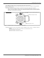
2Unpacking to Installation
2.2 Installation
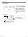
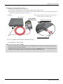
2.2.1 Unpacking
Pull off
引き抜く
<1>
Tape
①テープ
②上ブタ
<2> Upper lid
The fork
insertion
フォークリフトの爪
slots 挿入口
for a forklift truck
(b)
(a)
Robot arm
ロボット本体
!
CAUTION
!
Always unpack the
robot at a flat place.
The robot could tilt
over if unpacked at an
unstable place.
(c)
Note) Although the figure is the example of RV-4F other types are
the same also.
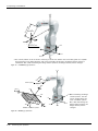
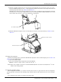
Fig.2-1 : Unpacking the robot arm
The robot is shipped from the factory in cardboard and plywood packing. Always refer to Fig. 2-1 and unpack the
robot.
Handle the robot arm according to "2.2.2Transportation procedures (Transporting with a crane)".
CAUTION
Always unpack the robot at a flat place. The robot could tilt over if unpacked at an
unstable place.
The unpacking process is shown below.
1) Using a knife, etc., slit the tape <1> fixing the upper lid <2> of the cardboard box. (Fig. 2-1 (a))
2) Pull the upper lid <2> of the cardboard box off with both hands. (Fig. 2-1 (b))
3) Remove the hexagon socket bolts <3> (four positions) connecting the sleeper and the base unit. (Fig. 2-1
(c))
4) This completes the unpacking.
Installation 2-8
2Unpacking to Installation
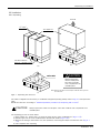
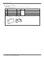
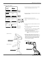
2.2.2 Transportation procedures (Transporting with a crane)
The transportation procedure is shown in Fig. 2-2 for (RV-4F/7F series) and Fig. 2-3 (RV-13F series).
RV-4F/RV-7F series
Mass
RV-4F series: Approx. 39kg
RV-4FL series: Approx. 41kg
RV-7F series: Approx. 65kg
RV-7FL series: Approx. 67kg
Wire
Fixing plate
Suspension fitting
Front
Note) The figure is the RV-4 F/
RV-4FL series. The shape
and installation screw of
the suspension fitting of
RV-7F/RV-7FL series
differ.
Side
Fig.2-2 : Transportation procedure (transporting with a crane: RV-4F/7F series)
RV-13F series
Mass
RV-13F series: Approx. 137kg
RV-13FL series: Approx. 145kg
Wire
Fixing plate
Suspension fitting
Front
Side
Fig.2-3 : Transportation procedure (transporting with a crane: RV-13F series)
2-9 Installation
2Unpacking to Installation
1) Attach the suspension fittings to the left and right sides of the shoulder section, and securely fix with
screws and plain washers. (RV-4F series: M6x20, each three screws for the right and left. RV-7F series:
M8x25, each two screws for the right and left. RV-13F series: M10x45, each two screws for the right and
left.)
(The suspension fittings are mounted on robot arm at factory shipping)
2) Catch wires in the eye bolts installed on the suspension fittings, and quietly suspend the arm.
Note) At this time, make sure that the wires, etc., do not interfere with the robot arm or covers. Always
place cloth, etc., at interfering places.
3) When transferring to the installation place, take care not to apply vibration or impact.
4) After installing at the installation place, remove the above suspension fittings.
5) Always follow the above procedures and methods to transport the robot for secondary transportation, such
as when changing the installation position.
If the arm is directly suspended without using the specified suspension fittings, or if it is suspended in the
work posture, the configuration devices could be damaged, and the transportation workers will be subject to
risk due to an inadequate center of gravity position.
Installation 2-10
2Unpacking to Installation
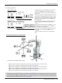
2.2.3 Installation procedures
The installation procedure of the robot arm is shown below.
FV
RV-4F series, RV-7F series:
4-M8x40
RV-13F series:
4-M12x55
Spring
washer
(Installation)
RV-4F series
MT
(Installation)
4-φ9 installation
hole
FH
FH
ML
Plain washer
ML
FH
FH
<Bottom view>
Robot’s
front
ロボット前方
FV
RV-13F series
(Installation)
(Installation)
RV-7F series
(Installation)
Robot’s
front
ロボット前方
4-φ9 installation hole
2-φ8H7 reamer bore
4-φ14 installation hole
(Installation)
Robot’s
front
ロボット前方
Fig.2-4 : Installation dimensions
1) The robot installation surface has been machine finished. Use the installation holes (RV-4F series and RV7F series: 4-φ9 holes, RV-13F series: 4-φ14 holes) opened at the four corners of the base, and securely
fix the robot with the enclosed installation bolts (RV-4F series and RV-7F series: M8 hexagon socket head
cap screws, RV-13F series: M12 hexagon socket head cap screws).
2) Installation of the robot arm is a very important step for ensuring the optimum functions of the robot.
Observe the following points when designing. Install the robot on a level surface.
3) It is recommended that the surface roughness of the table onto which the robot is to be installed by 6.3a or
more. If the installation surface is rough, the contact with the table will be poor, and positional deviation
could occur when the robot moves.
4) When installing, use a common table to prevent the position of the devices and jigs subject to robot work
from deviating.
5) The installation surface must have sufficient strength to withstand the arm reaction during operation, and
resistance against deformation and vibration caused by the static (dynamic) load of the robot arm and
peripheral devices, etc.
6) Remove the fixing plates after installing the robot. The fixing plate is needed in re-transportation. Please
keep it carefully.
7) When the robot is installed by hanging from the ceiling or on the wall, the MEGDIR parameter must be
changed. For more information about parameters and how to change the parameters, refer to the separate
"Instruction Manual/Detailed Explanation of Functions and Operations".
2-11 Installation
2Unpacking to Installation
8) The installation surface must have sufficient strength to withstand the arm reaction during moving the robot
at high speed.
Table 2-2 : Strength of the installation side (reference)
Item
Unit
Value
RV-4F/7F series
RV-13F series
Falling moment : ML
Nm
900
2,060
Twist moment
Nm
900
2,060
Horizontal translation power : FH
N
1,000
1,750
Vertical translation power N
1,700
2,900
: MT
CAUTION
: FV
Please secure the maintenance space required for connection of the machine cable and
exchange the backup battery in the rear side, and also space for J1 axis belt in the right
side. And don't install the robot arm in the position where direct rays or the heat of
lighting hits. The skin temperature of the robot arm may rise, and the error may occur.
Installation 2-12
2Unpacking to Installation
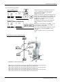
2.2.4 Grounding procedures
(1) Grounding methods
Robot arm
Controller
and
personal
computer
(a) Dedicated grounding
(Optimum)
Robot arm
Controller
and
personal
computer
(b) Common grounding
(Good)
Robot arm
Controller
and
personal
computer
(c) Common grounding
(Normal)
1) There are three grounding methods as shown in
Fig. 2-5, but the dedicated grounding (Fig. 2-5 (a))
should be used for the robot arm and controller
when possible. (Refer to the separate " Controller
Setup, Basic Operation and Maintenance" for
details on the controller grounding.)
2) Use Class D grounding (grounding resistance
100Ω or less).
Dedicated grounding separated from the other
devices should be used.
3) Use a AWG#11(4.2mm2) or more stranded wire for
the grounding wire. The grounding point should be
as close to the robot arm and controller as possible, and the length of the grounding wire should
be short.
Fig.2-5 : Grounding methods
(2) Grounding procedures
1) Prepare the grounding cable (AWG#11(4.2mm2) or
more) and robot side installation screw and washer.
M4x10
Spring washer
Plain washer
2) If there is rust or paint on the grounding screw
section (A), remove it with a file, etc.
3) Connect the grounding cable to the grounding
screw section.
A
本体接地用ケーブル (AWG #11(4.2mm2)以上)
(お客様にてご手配ください)
Robot grounding
cable (AWG#11 (4.2mm2) or more)
(Prepared by customer)
Note) Although the figure is the example of RV-4F other types are
the same also.
Fig.2-6 : Connecting the grounding cable
2-13 Installation
2Unpacking to Installation
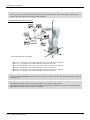
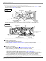
2.2.5 Connecting with the controller
(1) CR750 controller
Motor
power
モータパワー
(CN1)
(CN1)
Motor
signal
モータ信号
(CN2)
(CN2)
CN1
Robot
arm
ロボット本体
(Rear
of the base.)
(ベース部背面)
Note) Although the figure is the
example of RV-4F other types
are the same also.
CN2
Latch
ラッチ
Latch
ラッチ
CN1
Motor
signal cable
モータ信号ケーブル
CN2
Latch
ラッチ
ラッチ
Latch
Motor
power cable
モータパワーケーブル
Fig.2-7 : Connecting the machine cables
Carry out the following procedure after installing the controller referring to the separate "Controller Setup, Basic
Operation and Maintenance" manual.
Robot arm
ロボット本体
Connector on the
robot arm side
ロボット本体側コネクタ
Hook
固定フック
Projection
突起部
1) The procedure of connecting the machine cable is shown
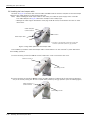
below.
2) Make sure that the power switch on the front of the
controller is turned OFF.
Note) Although the figure is RH-6FH, also in other robots
with same connector type, the connection method is
the same.
3) Connect the machine cable to its corresponding connector
on the robot arm side.
Connector on the
machine cable side
機器間ケーブル側コネクタ
4) After connecting the connector, insert the hook attached
to the connector on the machine cable side to the rear of
the projection of the robot arm connector to fix securely in
place.
CAUTION
Hook
固定フック
Be careful not to get your hand
pinched.
Projection
突起部
This complete the connection of machine cable.
Installation 2-14
2Unpacking to Installation
To remove the cable, insert a minus screwdriver into the hook
while padding with a cloth, and remove the cable by lifting the
hook.
Hook
Projection
Minus screwdriver
CAUTION
Padding
CAUTION
CAUTION
CAUTION
CAUTION
2-15 Installation
When installing or removing the connector, to the connector
of the other party in parallel, install or remove. If load strong
against one side is applied, the connector pin may be
damaged and it may not be connected securely.
The machine cable connectors are dedicated for the controller side and robot arm
side, so take special care when connecting.
If connected incorrectly, the connector pins could bend or break. Thus, even if
connected correctly, the robot will not operate correctly, creating a dangerous
situation.
Take special care to the leading of the connection cable. If the cable is pulled with
force or bent excessively, wires could break or the connector could be damaged.
Connect the machine cable at the place without the effect of the dust or oil mist.
Please keep the dust and oil mist from being applied to of the robot-arm connector
section, in the condition that the machine cable is removed. Since it becomes the
cause of failure.
Please be careful not to catch the hand at installation and removal.
2Unpacking to Installation
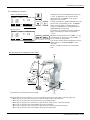
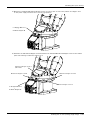
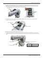
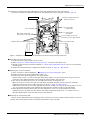
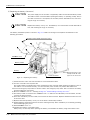
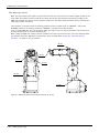
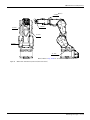
(2) CR751 controller
Motor
power (CN1)
モータ電源(CN1)
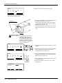
AMP1 AMP2 BRK
Note2)
Robot arm
ロボット本体
Opposite side of(背面)
figure
Motor
signal (CN2)
モータ信号(CN2)
Note1)
Controller
コントローラ前面
CONBOX cover
CONBOXカバー
CN2
CN1
Two
fixing screws
固定ネジ
(2箇所)
Two
fixing screws
固定ネジ
(2箇所)
Motor signal cable
モータ信号ケーブル
Note1) Although the figure is RV-4F/
7F series controller, and RV13F series is also the same.
Note2) The robot arm photo is for
illustrative purposes only.
Refer to Table 2-3 for packing
pose of actual products.
Motor power cable
モータ電源ケーブル
Battery fixing plate
Fixing screws (2 places)
AMP2
CN2
Machine cables
Controller side
AMP1
CON cover
(Eight fixing screws)
Only for clean/oil-mist specification
Robot arm side
Pass into
the opening
Cable clamp fixing
plate
(Two plate with *1)
four screws each)
*1) The size of the cable clamp fixed plate fixed screw (four
screws each.) is as follows.
・ Standard specification: M4x12
・ Clean/oil-mist specification: M4x16
Table 2-3 : The packing pose for each type (reference)
Axis
RV-4F
RV-4FL
RV-4F
RV-4FL
(Unit: degree)
RV-13F
0
RV-13FL
J1
90
90
90
90
0
J2
-122
-121
-116
-115
-93
-93
J3
162
165
158
164
160
160
J4
0
0
0
0
0
0
J5
45
41
48
41
23
23
J6
0
0
0
0
0
0
Connection condition
Fig.2-8 : Connecting the machine cables (CR751)
Installation 2-16
2Unpacking to Installation
Carry out the following procedure after installing the controller and the robot arm referring to the separate
"Controller Setup, Basic Operation and Maintenance" and "ROBOT ARM SETUP & MAINTENANCE" manual. The
connection outline is shown in Fig. 2-8.
1) Make sure that the power switch on the front of the controller is turned OFF.
Note) Although the figure is RV-4F series, also in other robots with same connector type, the connection
method is the same.
2) Connect the machine cable connectors to its corresponding connectors on the robot arm side.
a) Remove the four screws holding the CONBOX cover, and remove the cover. (Refer to Page 76, "5.3.2
Installing/removing the cover" for details.)
And, the CON cover is installed to clean / oil-mist specification. Removes the eight fixing screws and
removes the CON cover. The opening which passes the connector is seen.
b) The battery fixing plate is inside the CONBOX cover. Remove the two fixing screws and remove the
battery fixing plate.
Note) Do not disconnecting the battery cable and connector.
c) Feed the connectors of robot side to the opening on the back of the robot base and Connect with the
corresponding connector. Connect the connector (AMP1, AMP2, CN2) securely.
d) Fix the cable clamp fixed plate of the machine cable with the attached fixing screw. Fix both cables
securely with the four screws, respectively.
e) Install the battery fixing plate securely as before. Be careful not to insert the cable.
f) Install the CONBOX cover securely as before. Be careful not to insert the cable.
3) Connects the machine cable to the corresponding connector of the controller. Connects the connector
(CN1(AMP1, AMP2, BRK), CN2) surely. Fix the two fixing screws securely, respectively. Tighten the fixing
screw of CN2 by 0.06-0.07 Nm.
This complete the connection of machine cable.
CAUTION
CAUTION
CAUTION
CAUTION
2-17 Installation
The machine cable connectors are dedicated for the controller side and robot arm
side, so take special care when connecting.
If connected incorrectly, the connector pins could bend or break. Thus, even if
connected correctly, the robot will not operate correctly, creating a dangerous
situation.
Take special care to the leading of the connection cable. If the cable is pulled with
force or bent excessively, wires could break or the connector could be damaged.
Connect the machine cable at the place without the effect of the dust or oil mist.
Please keep the dust and oil mist from being applied to of the robot-arm connector
section, in the condition that the machine cable is removed. Since it becomes the
cause of failure.
Please be careful not to catch the hand at installation and removal.
2Unpacking to Installation
2.2.6 About oil mist specification
(1) Piping for pressurization inside robot arm
In use in oil mist environment, please connect the φ8 air hose to the coupling for pressurization of the robot arm
base portion "AIR PURGE",
and pressurize the inside of the robot arm.
Refer to the separate "Standard specifications manual" for specification of air purge.
Coupling for
pressurization(φ8)
Note) Although the figure is the
example of RV-4F other types
are the same also.
Fig.2-9 : Air purge
2.2.7 About clean specification
(1) Piping for suction inside robot arm
In use of the robot of clean specification, please connect the φ8 air hose to the coupling for suction of the
robot body base portion "VACUUM", and suck the inside of the robot arm.
Refer to the separate "Standard specifications manual" for vacuum condition.
Coupling for
suction (φ8)
Note) Although the figure is the
example of RV-4F other types
are the same also.
Fig.2-10 : Vacuum
Installation 2-18
2Unpacking to Installation
2.3 Setting the origin
The origin is set so that the robot can be used with a high accuracy. After purchasing the robot, always carry out
this step before starting work. This step must also be carried out if the combination of robot and controller being
used is changed.
There are several methods for setting the origin, but the origin data input method will be explained here. Refer to
Page 98, "5.6 Resetting the origin" for the other methods.
The teaching pendant is required for this operation.
[Caution] If the origin data at shipment is erased due to out of battery, it is necessary to set the origin again.
Refer to Page 98, "5.6 Resetting the origin" and reset the origin using the jig method or ABS method.
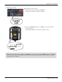
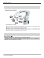
2.3.1 Installing the teaching pendant (T/B)
When installing and removing the T/B, turn off the controller power supply. If T/B is installed or removed in the
state of power supply ON, emergency stop alarm will occur.
If you use the robot wherein T/B is removed, please install the attached dummy connector. With the connector,
put the dummy connector or draw it out.
CAUTION
Please do not pull the cable of T/B strongly or do not bend it too much.
It becomes the breaking of a wire of the cable and the cause of breakage of the
connector. Please installing and removing so that stress does not start the cable
with the connector itself.
(1) Installing the T/B (CR750 controller)
Explain the installation method of T/B below.
1) Check that the POWER (power supply) switch of the robot controller is OFF.
2) Connects T/B connector to the robot controller. Use as the upper surface the lock lever shown in Fig. 2-11,
and push in until there is sound.
Details of
the A section
A部詳細
Dummy
connector
ダミーコネクタ
Controller
Lock
lever
ロックレバー
B
A
T/B
connector
T/B接続用コネクタ
When removing the connector for
T/B接続用コネクタを取り外す時は、
T/B connection, use lock release
ロック解除(ロックレバーを上側に起
こした状態)にし、B部のケースを手前
(state which raised the lock lever to
にスライドさせてラッチを外し引き抜き
the up side), make the case of the
ます。
B section slide to the front, and
remove and pull up out the latch.
Teaching
pendant
ティーチングボックス
(T/B)
(T/B)
Fig.2-11 : Installing and removing the T/B (CR750 controller)
The installation of T/B is finished.
◇◆◇ If error C0150 occurs ◇◆◇
At the time of the first power supply injection, error:C0150 (the serial number of the robot arm has not been
set up) occur the robot after purchase.
Parameter: Please input the serial number of the robot body into RBSERIAL. Refer to "instructions manual /
controller setup, and basic operation & maintenance" for the operation method.
2-19 Setting the origin
2Unpacking to Installation
(2) Installing the T/B (CR751 controller)
Explain the installation method of T/B below.
1) Check that the POWER (power supply) switch of the robot controller is OFF.
2) Connect the T/B connector to the controller’s T/B connector. Make sure to fix it securely by fastening the
hand locks (in 2 places), as shown in Fig. 2-12.
Note) Although the figure is RV-4F/7F series controller,
and RV-13F series is also the same.
Controller
T/B connector
Teaching
pendant
ティーチングボックス
(T/B)
Details of the A section
A部詳細
A部
A
T/B
connector
T/B接続用コネクタ
Hand lock
(Two places)
手回しロック(2箇所)
Fig. 2-12 : Installing and removing the T/B (CR751controller)
The installation of T/B is finished.
◇◆◇ If error C0150 occurs ◇◆◇
At the time of the first power supply injection, error:C0150 (the serial number of the robot arm has not been
set up) occur the robot after purchase.
Parameter: Please input the serial number of the robot body into RBSERIAL. Refer to "instructions manual /
controller setup, and basic operation & maintenance" for the operation method.
Setting the origin 2-20
2Unpacking to Installation
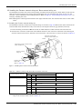
2.3.2 Setting the origin with the origin data input method
(1) Confirming the origin data
● Origin data history table (Origin Data History) Serial No.ES804008
Date
Default
D
V!#S29
J 1
06DTYY
J 2
2?HL9X
J 3
1CP55V
J 4
T6!M$Y
J 5
Z2IJ%Z
J 6
A12%Z0
Method
E
. . .
. . .
. . .
The origin data to be input is noted in the
origin data sheet enclosed with the arm,
or on the origin data history table
attached to the back side of the CONBOX cover. (Refer to Fig. 2-13).
Referring to Page 76, "5.3.2 Installing/
removing the cover", remove the CONBOX cover and confirm the value.
E ・ N ・ SP
E ・N・
SP
E ・ N ・ SP
(O: O(Alphabet), 0: Zero)
Note) Meanings of symbols in method column
E: Jig method
N: Not used
SP: Not used
The value given in the default setting
column is the origin settings set with the
calibration jig before shipment.
Fig.2-13 : Origin data label (an example)
WARNING
Always install/remove the cover with the controller control power turned OFF.
Failure to do so could lead to physical damage or personal injury should the robot
start moving due to incorrect operations.
(2) Turning ON the control power
CAUTION
Confirm that there are no operators near the robot before turning the power ON.
1) Turn the controller [POWER] switch ON.
The CR750 controller turns ON the front power switch.
2-21 Setting the origin
2Unpacking to Installation
(3) Preparing the T/B
Next, prepare to use the T/B
1) Set the mode of the controller to "MANUAL".
(The figure is example for CR750 controller)
MANUAL
MODE
AUTOMATIC
2) Set the T/B [ENABLE] switch to "ENABLE". The menu selection
screen will appear.
The following operations are carried out with the T/B.
Up:
Disable
上:DISABLE
Down: Enable
下:ENABLE
(Lighting)
*ランプ点灯
T/B背面
◇◆◇ Operating from the T/B ◇◆◇
Always set the mode of the controller to "MAMNUAL", and then set the T/B [ENABLE] switch to "ENABLE".
When the T/B is valid, only operations from the T/B are possible. Operations from the controller or external signals will not be accepted.
Setting the origin 2-22
2Unpacking to Installation
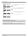
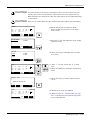
(4) Selecting the origin setting method
<MENU>
1.FILE/EDIT
3.PARAM.
5.SET/INIT.
1) Press the [4] key on the menu screen, and display the
ORIGIN/BRAKE screen.
2.RUN
4.ORIGIN/BRK
6.ENHANCED
CLOSE
123
<ORIGIN/BRAKE>
1.ORIGIN
2) Press the [1] key on the ORIGIN/BRAKE screen, and
display the origin setting method selection screen.
2.BRAKE
CLOSE
123
<ORIGIN>
1.DATA
3.TOOL
5.USER
2.MECH
4.ABS
3) Press the [1] key on the origin setting method selection
screen, and select the data input method.
123
CLOSE
) J2(
) J5(
) J8(
123
D:(■
) J3(
) J6(
)
CLOSE
4) Display the origin data input screen
<ORIGIN> DATA
J1(
J4(
J7(
)
)
)
◇◆◇ Selecting a menu ◇◆◇
The menu can be selected with one of the following methods.
A: Press the numeral key for the No. of the item to be selected.
B: Using the [ ↓ ] and [ ↑ ] keys, etc., move the cursor to the item to be selected, and then press the [INP] key.
◇◆◇ The input method of numeral ◇◆◇
The number can be inputted if the key displayed on the lower left of each key is pressed. Press the
[CHARACTER] key, and in the condition that "123" is displayed on the screen lower side, press the number key.
2-23 Setting the origin
2Unpacking to Installation
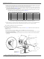
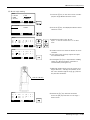
(5) Inputting the origin data
Origin data label
(D,J1,J2,J3,J4,J5,J6,J7,J8)
T/B screen
<ORIGIN> DATA
J1(
J4(
J7(
) J2(
) J5(
) J8(
123
D:(■
) J3(
) J6(
)
CLOSE
)
)
)
Input the value confirmed in section Page 21, "(1)
Confirming the origin data".
The correspondence of the origin data label value and axis to
be input is shown in Fig. 2-14.
Fig.2-14 : Correspondence of origin data label and axis
The method for inputting the origin data is explained below. The value shown in Fig. 2-13 will be input as an
example.
<ORIGIN> DATA
J1(
J4(
J7(
) J2(
) J5(
) J8(
123
D:(■
) J3(
) J6(
)
CLOSE
1) Confirm that the cursor is at the "D" position on the T/B
display screen.
)
)
)
2) Input the D value "V!%S29".
Inputting "V"
Press the [CHARACTER] key and set to the character input
mode. (Condition that "ABC" was displayed under the
screen)
Press the [TUV] key three times. "V" will be set.
<ORIGIN> DATA
J1(
J4(
J7(
) J2(
) J5(
) J8(
ABC
123
)
D:(V
) J3(
)
) J6(
)
)
CLOSE
<ORIGIN> DATA
J1(
J4(
J7(
) J2(
) J5(
) J8(
ABC
123
D:(V!
) J3(
) J6(
)
CLOSE
)
)
)
,
,
Press the [CHARACTER] key and set to the numeral input
mode. (Condition that "123" was displayed under the
screen)
Press the [2] key (input "2"), and press the [9] key (input
"9").
"V!%S29" will appear at the "D" data on the teaching
pendant screen.
<ORIGIN> DATA
J1(
J4(
J7(
) J2(
) J5(
) J8(
123
D:(V!%S29)
) J3(
)
) J6(
)
)
CLOSE
<ORIGIN> DATA
J1(
J4(
J7(
) J2(
) J5(
) J8(
123
D:(V!%S29)
) J3(
)
) J6(
)
)
CLOSE
Inputting "!"
Press the [ , % ] key five times. "!" will be set.
Press the [ → ] key once and advance the cursor.
Press the [ , % ] key twice (input "%"), and press the [PQRS]
key four times (input "S").
:
:
:
3) Press the [ ↓ ] key, and move the cursor to the J1 input
position.
4) Input the J1 value in the same manner as above.
5) Input the J2, J3, J4, J5 and J6 values in the same manner.
Setting the origin 2-24
2Unpacking to Installation
<ORIGIN> DATA
J1(
J4(
J7(
D:( V!%S29)
06DTYY) J2( 2?HL9X) J3( 1CP55V)
T6!MSY) J5( Z21J%Z) J6( A12%Z0)
) J8(
)
CLOSE
ABC
6) After inputting all of the values, press the [EXE] key. The
origin setting confirmation screen will appear.
7) Press [F1] (Yes) to end the origin setting
<ORIGIN>
DATA
CHANGE TO ORIGIN. OK?
Yes
123
No
◇◆◇ Moving the cursor ◇◆◇
Press the [ ↑ ], [ ↓ ], [ ← ] and [ → ] keys.
◇◆◇ Inputting characters ◇◆◇
Press the [CHARACTER] key and set to the character input mode. (Condition that "ABC" was
displayed under the screen). The displayed character is scrolled each time at pressing the key.
◇◆◇ How to input symbols ◇◆◇
The symbol is allocated to ['()], [@=], and [,%] key. Please repress each key until the symbol to wish is displayed.
a) ['()] key .......................... ' ( ) " ^ : ; \ ?
b) [@=] key......................... @ = + - * / < >
c) [,%] key........................... , % # $ ! & _ .
◇◆◇ Correcting an input ◇◆◇
After returning one character by pressing the [CLEAR] key, input the character again.
(6) Installing the CONBOX cover.
Return the CONBOX cover removed in section Page 21, "(1) Confirming the origin data" to its original position.
This completes the setting of the origin with the origin data input method.
WARNING
Removing and installing the cover by always turning off the controller power.
Failure to do so could lead to the robot moving because of incorrect operations, or
to physical damage or personal injury.
◇◆◇ If the origin input data is incorrect ◇◆◇
If the origin input data is incorrect, the alarm No. 1760 (origin setting data illegal) will occur when origin data input.
In this case, reconfirm the value input for the origin data.
2-25 Setting the origin
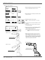
2 Unpacking to Installation
2.4 Confirming the operation
In this section, the robot will be moved manually using the T/B to confirm that the operation is correct.
Moving the robot manually is called "jog operation". This operation includes the JOINT jog that moves each axis,
the XYZ jog that moves along the base coordinate system, the TOOL jog that moves along the tool coordinate
system, and the CYLNDER jog that moves along the circular arc.
This operation is carried out while pressing the deadman switch on the back of the T/B.
Note) The figure of the robot which indicated to the explanation page in each jog mode is an example.
CAUTION
CAUTION
WARNING
The robot will move during this operation. Make sure that there are no operators
near the robot, and that there are no obstacles, such as tools, in the robot operation
range.
To immediately stop the robot, release the deadman switch on the back of the T/B.
The servo power will turn OFF, and the robot will stop.
The robot will also stop if the [EMG.STOP] switch (emergency stop switch) on the
front of the T/B or the [EMG.STOP] switch (emergency stop) on the front of the
controller is pressed.
Confirm that the origin has been set. If the origin has not been set, "****" will
appear at the current position display on the teaching pendant, the JOINT jog operation will take place in any jog mode selected.
Refer to Page 19, "2.3 Setting the origin" for details on setting the origin.
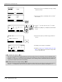
◇◆◇ How to choose the jog mode ◇◆◇
JOINT
JOINT
<CURRENT>
J1: +0.00
J2: +0.00
J3: +90.00
J4: +0.00
XYZ
TOOL
100%100%
M1 M1
TO T0B1
J5:
J6:
:
:
JOG
3-XYZ
Choose the jog mode +0.00
+0.00
~
CYLNDR ⇒
Press the [JOG] key, the jog screen will be
displayed, and display the jog mode which can be
chosen at the bottom of the screen. Because
these correspond to the function key of [F1] - [F4],
press the function key corresponding to the jog
mode to wish. And, if the [FUNCTION] key is
pressed, selection in jog modes other than the
present display is possible. The override (100%),
the mechanism number (M1), and the tool number
(T1), and the base coordinate number (B1) are
displayed on the upside of the screen following the
present jog mode (JOINT).
Confirming the operation 2-26
2 Unpacking to Installation
J4
axis
J4軸
+
-
J3
axis
J3軸
J5J5軸
axis
-
+
-
+
+
J6J6軸
axis
-
J2
axis
J2軸
-
-
+
J1 J1軸
axis
+
* Each axis moves independently.
Fig.2-15 : JOINT jog operation
+Z
th
ng 長
ル
e
l
l
ooー
Tツ
+Z
-
+
+X -
+
-
+
+Y
Control制御点
point
-X
-Y
+Y
+X
-Z
* While maintaining the flange surface posture, the axis moves straight along the base coordinate system.
Also, while maintaining the flange surface position, the flange surface posture changes.
Fig.2-16 : XYZ jog operation
2-27 Confirming the operation
2 Unpacking to Installation
-X
th
ng長
e
ル
l
l
ooー
Tツ
-Y
-Z
-
+
-
+Z
Control制御点
point
+ +Y
-
+
+X
* While maintaining the flange surface posture, the axis moves straight along the tool coordinate system.
Also, while maintaining the flange surface position, the flange surface posture changes.
Fig.2-17 : TOOL jog operation
+Z
+
J4 axis
J4軸
th
-
ng長
leル
l
ooー
Tツ
J5J5軸
axis
-
+
+
J6
axis
J6軸
Control point
-
制御点
-X
-Y
+Y
+X
-Z
* The axis moves straight along the base coordinate system. At this time, the flange surface posture is
not maintained. Also, the flange surface posture changes. The flange surface position does not
change at this time. It is effective to change the posture of the wrist, with the position maintained.
Fig.2-18 : 3-axis XYZ jog operation
Confirming the operation 2-28
2 Unpacking to Installation
Tツ
ool
ーleル
ngt
h
長
+Z
Vertical
上下
Arc
円弧
Radius
半径
Control
制御点point
-X
-Y
+Y
+X
-Z
* The current position is set as the arc centering on the Z axis, and the axis moves along that arc, expands
and contracts in the radius direction, and moves vertically. At this time, the flange surface posture is
maintained. Also, while maintaining the flange surface position, the flange surface posture changes.
Fig.2-19 : CYLINDER jog operation
+Z
th
ng
長
e
l
olル
Toー
ツ
Control point
-
-Yw
+Xw +
+Zw
+
-
-Xw
-Y
-
-Zw
+
WORK coordinate system
Fig.2-20 : WORK jog operation
2-29 Confirming the operation
* While maintaining the flange
surface posture, the axis
moves straight along the
work coordinate system.
Also, while maintaining the
+Y
flange surface position, the
flange surface posture
changes.
-X
+Yw
+X
-Z
2 Unpacking to Installation
(1) JOINT jog operation
Select joint jog mode
<CURRENT>
J1:
J2:
J3:
J4:
JOINT
+0.00
+0.00
+90.00
+0.00
J5:
J6:
:
:
TOOL
XYZ
100% M1
+0.00
+0.00
3-XYZ
JOG
T0
CYLNDR ⇒
Joint jog mode
Set jog speed
<CURRENT>
J1:
J2:
J3:
J4:
XYZ
JOINT
+0.00
+0.00
+90.00
+0.00
TOOL
100% M1
J5:
J6:
:
:
JOG
3-XYZ
T0
+0.00
+0.00
CYLNDR ⇒
Setting the speed
[JOG] Press the key and display the jog screen.
("JOG" is displayed on the screen bottom)
Check that the "joint" in jog mode is displayed on
the screen.
If other jog modes are displayed, please press the
function key corresponding to the "joint." (If the
jog mode which he wishes under the screen is not
displayed, it is displayed that the [FUNCTION]
key is pressed)
If it finishes jog operation, press the [JOG] key
again, or function key which correspond to
"close."
Whenever it presses the key of [OVRD ↑ ], the
override goes up. Conversely, if the [OVRD ↓ ]
key is pressed, it will go down.
The current setting speed is displayed on screen
upper right, and "STATUS NUMBER" of the
controller.
Set the override to 10% here for confirmation
work
J1 axis jog operation
-
+
J1 axis
J1軸回転
・ When the [+X (J1)] keys are pressed, the J1 axis will rotate in the plus direction.
When the [-X (J1)] keys are pressed, Rotate in the minus direction.
J2 axis jog operation
・ When the [+Y (J2)] keys are pressed, the J2 axis will rotate in the plus direction.
When the [-Y (J2)] keys are pressed, Rotate in the minus direction.
Confirming the operation 2-30
2 Unpacking to Installation
◇◆◇ When the robot is in the transportation posture ◇◆◇
The axes may be outside the movement area. Move these axes toward the inner side of the movement area.
J3 axis jog operation
-
J3 axis
J3軸回転
+
・ When the [+Z (J3)] keys are pressed, the J3 axis will rotate in the plus direction.
When the [-Z (J3)] keys are pressed, Rotate in the minus direction.
J4, J5 and J6 axis jog operation
J5J5軸
axis
-
+ J4 axis
J4軸
+
-
,
+
J6
axis
J6軸
・ When the
When the
・ When the
When the
・ When the
When the
-
SPACE
[+A (J4)] keys are pressed, the J4 axis will rotate in the plus direction.
[-A (J4)] keys are pressed, Rotate in the minus direction.
[+B (J5)] keys are pressed, the J5 axis will rotate in the plus direction
[-B (J5)] keys are pressed, Rotate in the minus direction.
[+C (J6)] keys are pressed, the J6 axis will rotate in the plus direction
[-C (J6)] keys are pressed, Rotate in the minus direction.
◇◆◇If the buzzer of T/B sounds and the robot does not move ◇◆◇
If it is going to move the robot across the operation range, the buzzer of T/B sounds and the robot does not
move. In this case, please move to the counter direction.
2-31 Confirming the operation
2 Unpacking to Installation
(2) XYZ jog operation
Select XYZ jog mode
<CURRENT>
J1:
J2:
J3:
J4:
JOINT
+0.00
+0.00
+90.00
+0.00
J5:
J6:
:
:
TOOL
XYZ
100% M1
JOG
T0
+0.00
+0.00
3-XYZ
CYLNDR ⇒
XYZ jog mode
Set jog speed
<CURRENT>
J1:
J2:
J3:
J4:
XYZ
JOINT
+0.00
+0.00
+90.00
+0.00
TOOL
100% M1
J5:
J6:
:
:
JOG
T0
+0.00
+0.00
3-XYZ
CYLNDR ⇒
Setting the speed
[JOG] Press the key and display the jog screen.
("JOG" is displayed on the screen bottom)
Check that the "XYZ" in jog mode is displayed on
the screen.
If other jog modes are displayed, please press the
function key corresponding to the "XYZ." (If the
jog mode which he wishes under the screen is not
displayed, it is displayed that the [FUNCTION]
key is pressed)
If it finishes jog operation, press the [JOG] key
again, or function key which correspond to
"close."
Whenever it presses the key of [OVRD ↑ ], the
override goes up. Conversely, if the [OVRD ↓ ]
key is pressed, it will go down.
The current setting speed is displayed on screen
upper right, and "STATUS NUMBER" of the
controller.
Set the override to 10% here for confirmation
work.
Moving along the base coordinate system
+Z
+Z
h
gt
n長
e
l
ル
ol
ー
Tツo
+Y
+X
-X
-Y
* The direction of the flange will not change
+Y
+X
-Z
・ When the [+X (J1)] keys are pressed, the robot will move along the X axis plus direction.
When the [-X (J1)] keys are pressed, Move along the minus direction.
・ When the [+Y (J2)] keys are pressed, the robot will move along the Y axis plus direction.
When the [-Y (J2)] keys are pressed, Move along the minus direction.
・ When the [+Z (J3)] keys are pressed, the robot will move along the Z axis plus direction.
When the [-Z (J3)] keys are pressed, Move along the minus direction.
◇◆◇ When the robot is in the transportation posture ◇◆◇
There are directions from which linear movement is not possible from the transportation posture. In this case, the
robot will not move. Refer to section Page 30, "(1) JOINT jog operation"", and move the robot to a position where
linear movement is possible, and then carry out XYZ jog.
Confirming the operation 2-32
2 Unpacking to Installation
◇◆◇If the buzzer of T/B sounds and the robot does not move ◇◆◇
If it is going to move the robot across the operation range, the buzzer of T/B sounds and the robot does not
move. In this case, please move to the counter direction.
Changing the flange surface posture
SPACE
+Z
+Z
-
,
+
h
gt
n長
e
lル
+
+X -
Control
point
制御点
oーl
Tツo
-
+Y
+
-X
-Y
* The control point does not change.
・ When the
When the
・ When the
When the
・ When the
When the
+Y
+X
-Z
[+A (J4)] keys are pressed, The X axis will rotate in the plus direction.
[-A (J4)] keys are pressed, Rotate in the minus direction.
[+B (J5)] keys are pressed, The Y axis will rotate in the plus direction.
[-B (J5)] keys are pressed, Rotate in the minus direction.
[+C (J6)] keys are pressed, The Z axis will rotate in the plus direction.
[-C (J6)] keys are pressed, Rotate in the minus direction.
◇◆◇ When alarm No. 5150 occurs ◇◆◇
If alarm No. 5150 (ORIGIN NOT SET) occurs, the origin has not been set correctly. Reconfirm the value input for
the origin data.
◇◆◇ Tool length ◇◆◇
The default tool length is 0mm, and the control point is the center of the end axis.
After installing the hand, set the correct tool length in the parameters. Refer to the separate manual "Detailed
Explanation of Functions and Operations" for details.
2-33 Confirming the operation
2 Unpacking to Installation
(3) TOOL jog operation
Select TOOL jog mode
<CURRENT>
J1:
J2:
J3:
J4:
JOINT
100% M1
+0.00
+0.00
+90.00
+0.00
J5:
J6:
:
:
TOOL
XYZ
JOG
T0
+0.00
+0.00
~
3-XYZ
CYLNDR ⇒
TOOL jog mode
Set jog speed
<CURRENT>
J1:
J2:
J3:
J4:
XYZ
JOINT
100% M1
+0.00
+0.00
+90.00
+0.00
TOOL
J5:
J6:
:
:
JOG
3-XYZ
T0
+0.00
+0.00
CYLNDR ⇒
Setting the speed
[JOG] Press the key and display the jog screen.
("JOG" is displayed on the screen bottom)
Check that the "TOOL" in jog mode is displayed
on the screen.
If other jog modes are displayed, please press the
function key corresponding to the "TOOL." (If
the jog mode which he wishes under the screen is
not displayed, it is displayed that the [FUNCTION] key is pressed)
If it finishes jog operation, press the [JOG] key
again, or function key which correspond to
"close."
Whenever it presses the key of [OVRD ↑ ], the
override goes up. Conversely, if the [OVRD ↓ ]
key is pressed, it will go down.
The current setting speed is displayed on screen
upper right, and "STATUS NUMBER" of the
controller.
Set the override to 10% here for confirmation
work
Moving along the tool coordinate system
h
gt
n長
e
ル
l
ー
ol
Tツo
+Y
+Z
Control
point
制御点
+X
* The direction of the flange will not change
・When the [+X (J1)] keys are pressed, the robot will move along the X axis plus direction of the tool coordinate
system.
When the [-X (J1)] keys are pressed, Move along the minus direction.
・When the [+Y (J2)] keys are pressed, the robot will move along the Y axis plus direction of the tool coordinate
system.
When the [-Y (J2)] keys are pressed, Move along the minus direction.
・When the [+Z (J3)] keys are pressed, the robot will move along the Z axis plus direction of the tool coordinate
system.
When the [-Z (J3)] keys are pressed, Move along the minus direction.
◇◆◇ When the robot is in the transportation posture ◇◆◇
There are directions from which linear movement is not possible from the transportation posture. In this case, the
robot will not move. Refer to section Page 30, "(1) JOINT jog operation"", and move the robot to a position where
linear movement is possible, and then carry out XYZ jog.
Confirming the operation 2-34
2 Unpacking to Installation
◇◆◇If the buzzer of T/B sounds and the robot does not move ◇◆◇
If it is going to move the robot across the operation range, the buzzer of T/B sounds and the robot does not
move. In this case, please move to the counter direction.
Changing the flange surface posture
th
ng長
ル
e
ーl l
oo
Tツ
-
,
+
+Z
-
+ +Y
-
SPACE
+
+X
* The control point does not change.
・When the[+A (J4)] keys are pressed, The X axis will rotate in the plus direction of the tool coordinate system.
When the[-A (J4)] keys are pressed, Rotate in the minus direction.
・ When the[+B (J5)] keys are pressed, The Y axis will rotate in the plus direction of the tool coordinate system.
When the[-B (J5)] keys are pressed, Rotate in the minus direction.
・When the[+C (J6)] keys are pressed, The Z axis will rotate in the plus direction of the tool coordinate system.
When the[-C (J6)] keys are pressed, Rotate in the minus direction.
◇◆◇ When alarm No. 5150 occurs ◇◆◇
If alarm No. 5150 (ORIGIN NOT SET) occurs, the origin has not been set correctly. Reconfirm the value input for
the origin data.
◇◆◇ Tool length ◇◆◇
The default tool length is 0mm, and the control point is the center of the end axis.
After installing the hand, set the correct tool length in the parameters. Refer to the separate manual "Detailed
Explanation of Functions and Operations" for details.
2-35 Confirming the operation
2 Unpacking to Installation
(4) 3-axis XYZ jog operation
Select XYZ456 jog mode
<CURRENT>
J1:
J2:
J3:
J4:
JOINT
+0.00
+0.00
+90.00
+0.00
J5:
J6:
:
:
TOOL
XYZ
100% M1
JOG
T0
+0.00
+0.00
3-XYZ
~
CYLNDR ⇒
XYZ456 jog mode
Set jog speed
<CURRENT>
J1:
J2:
J3:
J4:
XYZ
JOINT
+0.00
+0.00
+90.00
+0.00
TOOL
100% M1
J5:
J6:
:
:
JOG
T0
+0.00
+0.00
3-XYZ
CYLNDR ⇒
Setting the speed
[JOG] Press the key and display the jog screen.
("JOG" is displayed on the screen bottom)
Check that the "XYZ456" in jog mode is
displayed on the screen.
If other jog modes are displayed, please press the
function key corresponding to the "XYZ456." (If
the jog mode which he wishes under the screen is
not displayed, it is displayed that the [FUNCTION] key is pressed)
If it finishes jog operation, press the [JOG] key
again, or function key which correspond to
"close."
Whenever it presses the key of [OVRD ↑ ], the
override goes up. Conversely, if the [OVRD ↓ ]
key is pressed, it will go down.
The current setting speed is displayed on screen
upper right, and "STATUS NUMBER" of the
controller.
Set the override to 10% here for confirmation
work
Moving along the base coordinate system
+Z
Toツ
oー
l leル
ng長
th
+Z
+Y
+X
-X
-Y
* The direction of the flange will change
+Y
+X
-Z
・ When the[+X (J1)] keys are pressed, the robot will move along the X axis plus direction.
When the[-X (J1)] keys are pressed, Move along the minus direction.
・ When the[+Y (J2)] keys are pressed, the robot will move along the Y axis plus direction.
When the[-Y (J2)] keys are pressed, Move along the minus direction.
・ When the[+Z (J3)] keys are pressed, the robot will move along the Z axis plus direction.
When the[-Z (J3)] keys are pressed, Move along the minus direction.
Confirming the operation 2-36
2 Unpacking to Installation
◇◆◇ The flange surface end axis posture cannot be maintained with 3-axis XYZ jog. ◇◆◇
With 3-axis XYZ jog, the flange surface end axis posture (orientation) is not maintained when moving linearly in
the X, Y or Z axis direction.
Use XYZ jog to maintain the posture.
Changing the flange surface posture
J5
axis
J5軸
-
+ J4軸
J4 axis
+
-
,
+
J6 axis
J6軸
-
SPACE
* The wrist pose can be changed maintaining the
flange's position.
・ When the[+A (J4)] keys are pressed, the J4-axis will rotate in the plus direction.
At this time, to maintain the flange's position, other axes move simultaneously except J5 and J6.
When the[-A (J4)] keys are pressed, Rotate in the minus direction.
・ When the[+B (J5)] keys are pressed, the J5-axis will rotate in the plus direction.
At this time, to maintain the flange's position, other axes move simultaneously except J4 and J6.
When the[-B (J5)] keys are pressed, Rotate in the minus direction.
・ When the[+C (J6)] keys are pressed, the J6-axis will rotate in the plus direction.
When the[-C (J6)] keys are pressed, Rotate in the minus direction.
2-37 Confirming the operation
2 Unpacking to Installation
(5) CYLNDER jog operation
Select cylindrical jog mode
<CURRENT>
J1:
J2:
J3:
J4:
JOINT
+0.00
+0.00
+90.00
+0.00
J5:
J6:
:
:
TOOL
XYZ
100% M1
JOG
T0
+0.00
+0.00
~
3-XYZ
CYLNDR ⇒
CYLNDER jog mode
Set jog speed
<CURRENT>
J1:
J2:
J3:
J4:
XYZ
JOINT
+0.00
+0.00
+90.00
+0.00
TOOL
100% M1
J5:
J6:
:
:
JOG
3-XYZ
T0
+0.00
+0.00
CYLNDR ⇒
Setting the speed
[JOG] Press the key and display the jog screen.
("JOG" is displayed on the screen bottom)
Check that the "CYLNDER" in jog mode is
displayed on the screen.
If other jog modes are displayed, please press the
function key corresponding to the "CYLNDER."
(If the jog mode which he wishes under the
screen is not displayed, it is displayed that the
[FUNCTION] key is pressed)
If it finishes jog operation, press the [JOG] key
again, or function key which correspond to
"close."
Whenever it presses the key of [OVRD ↑ ], the
override goes up. Conversely, if the [OVRD ↓ ]
key is pressed, it will go down.
The current setting speed is displayed on screen
upper right, and "STATUS NUMBER" of the
controller.
Set the override to 10% here for confirmation
work
Moving along an arc centering on the Z axis
+Z
Tツ
ooー
l le
ng長
ル
th
Vertical
上下
-
Radius
半径
Arc
円弧
+
-X
Control
制御点
point
-Y
* The direction of the frange will not change.
+Y
+X
-Z
Assuming that the current position is on an arc centering on the Z axis, the robot moves along that arc.
・ When the[+X (J1)] keys are pressed, the robot will expand in the radial direction.
When the[-X (J1)] keys are pressed, Contract in the radial direction.
・ When the[+Y (J2)] keys are pressed, the robot will move along the arc in the plus direction.
When the[-Y (J2)] keys are pressed, Move in the minus direction.
・ When the[+Z (J3)] keys are pressed, the robot will move along the Z axis plus direction.
When the[-Z (J3)] keys are pressed, Move along the minus direction.
Confirming the operation 2-38
2 Unpacking to Installation
Changing the flange surface posture
+Z
SPACE
+Z
-
,
+
h
gt
長
len
ル
l
o
ー
To
ツ
+
+X -
-
Control
制御点
point
+
+Y
-X
-Y
* The flange position does not change.
This is the same as the A, B and C axis XYZ jog
operation.
+Y
+X
-Z
・ When the [+A (J4)] keys are pressed, The X axis will rotate in the plus direction.
When the [-A (J4)] keys are pressed, Rotate in the minus direction.
・ When the [+B (J5)] keys are pressed, The Y axis will rotate in the plus direction.
When the [-B (J5)] keys are pressed, Rotate in the minus direction.
・ When the [+C (J6)] keys are pressed, The Z axis will rotate in the plus direction.
When the [-C (J6)] keys are pressed, Rotates in the minus direction.
2-39 Confirming the operation
2 Unpacking to Installation
(6) Work jog operation
Setting of the work coordinates system is necessary.
By this jog operation, robot can be move along with the direction of work (or working table etc.), so teaching
operations get easier.
When jog operation, select by which work coordinates the robot moves
The setting method of the work coordinates system using T/B (R32TB) is shown in the following.
(Parameter: Setting the coordinate value to WKnCORD ("n" is meaning the number (1-8) of work
coordinates) can also set up the work coordinates system. Refer to the separate manual "Detailed
Explanation of Functions and Operations" for details of parameter.)
The work coordinates system teaches and sets up the three points (WO, WX, WY).
+Z
+Zw
Notes) The figure is the example of
RV-6SD of our company, but
other types are the same
work coordinates
WO
+Y
WX
WY
+Xw
Work
The jogging movement
based on this work is
possible.
+Yw
Robot coordinates
system
+X
<
Teaching point>
WO: Work coordinates system origin
WX: Position on the "+X" axis of work coordinates system.
WY: Position at the side of "+Y" axis on the X-Y plane of work coordinates system
[Supplement] : The coordinate values which use all three teaching points for setting of the
work coordinates system are each only X, Y, and the Z-axis. Although the coordinate value of A, B, and C axis is not used, positioning will get easy if the XYZ
jog or TOOL jog movement is effected with the same value. (The direction of the
hand is the same)
Fig.2-21 : Setting of the work coordinates system (teaching point)
The setting (definition) method of the work coordinates system is shown in the following.
1) Select "6.ENHANCED" screen on the <MENU> screen.
<MENU> <EMHANCED> 1.FILE/EDIT
3.PARAM.
5.SET/INIT.
2.RUN
4.ORIGIN/BRK
6.ENHANCED
123
CLOSE
1.SQ DIRECT
2.WORK COORD.
123
CLOSE
Confirming the operation 2-40
2 Unpacking to Installation
2) Press the [2] keys in the menu screen and select "2. WORK COORD."
<EMHANCED> 1.SQ DIRECT
<WORK COORD>
2.WORK COORD.
123
CLOSE
WORK NUMBER (1)
TEACHING POINT (WO)
X: 0.00
Y: 0.00
Z: 0.00
WY
TEACH
DEFINE
WX 123
The screen shows the coordinate value of the origin
(WO) of the work coordinates number 1.
3) Selection of the work coordinates number
Press the [FUNCTION] keys, and display "W: JUMP" function. Press the function key corresponding to
"W: JUMP"
<WORK COORD>
WORK NUMBER (1)
TEACHING POINT (WO)
X: 0.00
Y: 0.00
Z: 0.00
W.JUMP W.GRID 123
<WORK JUMP>
CHOOSE ONE OF THE WORK NUMBER
1-8.
CLOSE
123
CLOSE
Press numeral key [1] - [8] and specify the work coordinates number. The coordinate value of the specified
work coordinates system is displayed.
<WORK COORD>
<WORK JUMP>
CHOOSE ONE OF THE WORK NUMBER
1-8.
CLOSE
123
Operation will be canceled if the
[CLOSE] key is pressed.
WORK NUMBER (2)
TEACHING POINT (WO)
X: 0.00
Y: 0.00
Z: 0.00
W.JUMP W.GRID 123
CLOSE
The screen is the example which specified
the work coordinates number 2. ("2" at the
upper right of the screen)
4) The teaching of the work coordinates system
Teach the three points shown in Fig. 2-21. Confirm the name currently displayed on the "TEACHING
POINT" at the upper right of the screen. If it differs, press the function key corresponding to each
point(WO, WX, WY) to teach. Move the robot's arm by jog operation (other jogging movement), and press
the function key corresponding to "TEACH."([F1]) The confirmation screen is displayed.
<WORK COORD>
WORK NUMBER (2)
TEACHING POINT (WO)
X: 0.00
Y: 0.00
Z: 0.00
TEACH
<WORK COORD>
WORK NUMBER (2)
TEACHING POINT (WO)
RECORD CURRENT POSITION.
OK?
WX 123
WY
DEFINE
Specify the teaching point [WO],[WX],[WY]
teaching the position [TEACH]
2-41 Confirming the operation
Yes
123
No
2 Unpacking to Installation
Presses the function key corresponding to"Yes", the robot's current position is registered, and the
registered coordinates value is displaye. Operation will be canceled if the [CLOSE] key is pressed.
<WORK COORD>
WORK NUMBER (2)
TEACHING POINT (WO)
RECORD CURRENT POSITION.
OK?
Yes
WORK NUMBER (2)
TEACHING POINT (WO)
X: 214.12
Y: -61.23
Z: 553.30
No
123
<WORK COORD>
W.JUMP W.GRID 123
CLOSE
Teach the three points, WO, WX, and WY, by the same operation.
The position data taught here is each registered into the following parameters. ("n" means the work coordinates numbers 1-8)
WO= parameter: WKnWO
WX= parameter: WKnWX
WY= parameter: WKnWY
5) Setting of work coordinates (definition)
If the function key corresponding to "DEFINE" ([F1]) is pressed, the work coordinates system will be
calculated using the three points, and the result will be displayed.
<WORK COORD>
WORK NUMBER (2)
TEACHING POINT (WO)
X: 214.12
Y: -61.23
Z: 553.30
TEACH
WX 123
WY
<WORK COORD>
WORK NUMBER (2)
WORK COORDINATES DATA
(3.53, -220.00, 5.14, 0.00, 0.
00, 0.00)
DEFINE
CLOSE
123
The alarm occurs if the work coordinates system is incalculable. (There are the three points on the straight
line, or the two points have overlapped) In this case, reset alarm and re-teach the three points.
This work coordinate data is registered into parameter: WKnCORD. ("n" means the work coordinates
numbers 1-8)
If the function key corresponding to "CLOSE" is pressed, it will return to the previous screen.
<WORK COORD>
WORK NUMBER (2)
WORK COORDINATES DATA
(3.53, -220.00, 5.14, 0.00, 0.
00, 0.00)
123
CLOSE
<WORK COORD>
WORK NUMBER (2)
TEACHING POINT (WO)
X: 214.12
Y: -61.23
Z: 553.30
TEACH
WX 123
WY
DEFINE
6) Finishing of setting the work coordinates
Press the [FUNCTION] keys, and display "CLOSE" function. Press the function key corresponding to
"CLOSE". Returns to the <MENU> screen.
<WORK COORD>
WORK NUMBER (2)
TEACHING POINT (WO)
X: 214.12
Y: -61.23
Z: 553.30
W.JUMP W.GRID
123
CLOSE
<EMHANCED> 1.SQ DIRECT
2.WORK COORD.
123
CLOSE
Confirming the operation 2-42
2 Unpacking to Installation
Although setting of work coordinates is finishing above, confirmation of work coordinates can be done by pressing the function key corresponding to "W GRID."([F2])
<WORK COORD>
WORK NUMBER (2)
TEACHING POINT (WO)
<WORK COORD>
WORK NUMBER (2)
WORK COORDINATES DATA
(3.53, -220.00, 5.14, 0.00, 0.
00, 0.00)
X: 214.12
Y: -61.23
Z: 553.30
CLOSE
W.JUMP W.GRID
123
123
CLOSE
Return to the previous screen by pressing
the [CLOSE] ([F4]) key.
Then, the operation method of the work jog is shown.
Change to the work jog after nearing the work.
Select WORK jog mode
<CURRENT>
J1:
J2:
J3:
J4:
WORK
+0.00
+0.00
+90.00
+0.00
TOOL
XYZ
100%
J5:
J6:
:
:
JOG
M1 T0 W1
+0.00
+0.00
~
3-XYZ
CYLNDR ⇒
WORK jog mode Confirmation and selection of the
work coordinates system
<CURRENT>
J1:
J2:
J3:
J4:
WORK
+0.00
+0.00
+90.00
+0.00
J5:
J6:
:
:
TOOL
XYZ
100%
JOG
M1 T0 W1
+0.00
+0.00
3-XYZ
CYLNDR ⇒
Select the work coordinates system
CAUTION
J1:
J2:
J3:
J4:
XYZ
JOINT
+0.00
+0.00
+90.00
+0.00
TOOL
100% M1
J5:
J6:
:
:
JOG
3-XYZ
T0
+0.00
+0.00
CYLNDR ⇒
Setting the speed
2-43 Confirming the operation
Target work
coordinates system
Confirm the target work coordinates system.
The current target number is displayed on the
screen upper right. (W1 - W8)
The number of work coordinates can be
changed by the arrow key [Upper arrow],
[Lower arrow]
Push the key [Upper arrow], the number will
increase. (W1, W2, ..... W8) Conversely, push
the key [Lower arrow], the number will
decrease
Always confirm that the number of the target work coordinates system is displayed
correctly (Display of W1-W8 at the upper right of the screen)
If mistaken, the robot will move in the direction which is not meant and will cause the
damage and the personal injuries.
Set jog speed
<CURRENT>
[JOG] Press the key and display the jog
screen. ("JOG" is displayed on the screen
bottom)
Check that the "WORK" in jog mode is
displayed on the screen.
If other jog modes are displayed, please press
the function key corresponding to the "WORK."
(If the jog mode which he wishes under the
screen is not displayed, it is displayed that the
[FUNCTION] key is pressed)
If it finishes jog operation, press the [JOG] key
again, or function key which correspond to
"close."
Whenever it presses the key of [OVRD(Upper
arrow)], the override goes up. Conversely, if
the [OVRD(Lower arrow)] key is pressed, it will
go down.
The current setting speed is displayed on
screen upper right, and "STATUS NUMBER" of
the controller.
Set the override to 10% here for confirmation
work
2 Unpacking to Installation
The jog movement based on work coordinates system
+Z
h
gt
n長
e
l
ル
l
oー
Toツ
Controll point
* The direction of the flange will not
change. Move the control point
with a straight line in accordance
with the work coordinates system
+Zw
+Xw
-X
-Y
+Y
+X
-Z
+Yw
Work coordinates system
・ When the[+X (J1)] keys are pressed, the robot will move along the X axis plus direction on the work
coordinates system.
When the[-X (J1)] keys are pressed, Move along the minus direction.
・ When the[+Y (J2)] keys are pressed, the robot will move along the Y axis plus direction on the work
coordinates system.
When the[-Y (J2)] keys are pressed, Move along the minus direction.
・ When the[+Z (J3)] keys are pressed, the robot will move along the Z axis plus direction on the work
coordinates system.
When the[-Z (J3)] keys are pressed, Move along the minus direction.
Changing the flange surface posture
+Z
th
ng
lルe長
l
o
Tツoー
SPACE
-
+Xw +
* The position of the control point
does not change. Change the
direction of the flange in
accordance with the work
coordinates system.
Controll point
+Zw
+
,
-
-X
-Y
-
+
+Y
+X
+Yw
-Z
Work coordinates system
Confirming the operation 2-44
2 Unpacking to Installation
・When the[+A (J4)] keys are pressed, The X axis will rotate in the plus direction of the work coordinate system.
When the[-A (J4)] keys are pressed, Rotate in the minus direction.
・When the[+B (J5)] keys are pressed, The Y axis will rotate in the plus direction of the work coordinate system.
When the[-B (J5)] keys are pressed, Rotate in the minus direction.
・When the[+C (J6)] keys are pressed, The Z axis will rotate in the plus direction of the work coordinate system.
When the[-C (J6)] keys are pressed, Rotate in the minus direction.
◇◆◇ When the robot is in the transportation posture ◇◆◇
There are directions from which linear movement is not possible from the transportation posture. In this case, the
robot will not move. Refer to section Page 30, "(1) JOINT jog operation"", and move the robot to a position where
linear movement is possible, and then carry out XYZ jog.
◇◆◇If the buzzer of T/B sounds and the robot does not move ◇◆◇
If it is going to move the robot across the operation range, the buzzer of T/B sounds and the robot does not
move. In this case, please move to the counter direction.
◇◆◇ Tool length ◇◆◇
The default tool length is 0mm, and the control point is the center of the end axis.
After installing the hand, set the correct tool length in the parameters. Refer to the separate manual "Detailed
Explanation of Functions and Operations" for details.
2-45 Confirming the operation
3Installing the option devices
3 Installing the option devices
3.1 Installing the J1 axis operating range change
The configuration, changeable angle and installation outline of J1 axis operating range change are shown below.
3.1.1 RV-4F/7F series (RV-4F : 1F-DH-03、 RV-7F : 1F-DH-04)
(1) Configuration
The configuration parts of this option are shown in Table 3-4. Please confirm.
Table 3-1 : Configuration devices
No.
Part name
Qty.
Mass (kg)
Remarks
RV-4F series
<1>
Stopper plate
2
One piece each for + side/- side
<2>
Fixing block A
2
One piece each for + side/- side
<3>
Fixing block B
1
+ side
<4>
Fixing block C
1
- side
1.1
<5>
Variable stopper block
2
One piece each for + side/- side
<6>
Screw (M10x20)
2
Use for mechanical stopper screw A and B
<7>
Screw (M6x25)
2
For fixing
<8>
Screw (M6x20)
16
For fixing
RV-7F series
<1>
Stopper plate
2
One piece each for + side/- side
<2>
Fixing block A
2
One piece each for + side/- side
<3>
Fixing block B
1
+ side
<4>
Fixing block C
1
- side
1.1
<5>
Variable stopper block
2
One piece each for + side/- side
<6>
Screw (M12x25)
2
Use for mechanical stopper screw A and B
<7>
Screw (M8x25)
14
For fixing
<8>
Screw (M8x20)
4
For fixing
<1> Stopper plate
<5> Variable stopper block
<2> Fixing block A
<3> Fixing block B
- (minus) side
<4> Fixing block C
<4>
<3>
<1>
<2>
<5>
+ (plus) side
Installing the J1 axis operating range change 3-46
3Installing the option devices
(2) Changeable angle
The changeable angle of RV-4F series is shown in Table 3-2, and of RV-7F series is shown in Table 3-3. Use as
reference for the installation position of Variable stopper block to the wished angle and use/disuse of the
Mechanical stopper screw A/B and the parameter setup value.
Table 3-2 : Changeable angle (RV-4F series)
Item
Standard
+ (plus) side
Variable stopper block angle
Variable stopper block position
Mechanical stopper screw A
Note1)
Note2)
Parameter (MEJAR) setting value
+ (minus) side
Variable stopper block angle
Variable stopper block position
Mechanical stopper screw B
Note1)
Note2)
Parameter (MEJAR) setting value
Changeable angle (combination of + side/- side) (Unit: Degree)
+240
+30
+73
+103
+146
-
+33
+76
+106
+149
-
(a)
(b)
(a)
-
Use
(b)
Disuse
Note3)
+240
+30
+73
+103
+146
-240
-30
-73
-103
-146
-
-33
-76
-106
-149
-
(d)
(c)
(d)
(c)
-240
Use
-30
Disuse
-73
Note3)
-103
-146
Note1)Symbol: “(a)” - “(d)” in the Table 3-2 is related with the symbol of "Fig. 3-1: Installation image of J1axis operating
range change option".
Note2)In the table, it means that “Disuse” does not install the screw, and “Use” does install the screw.
Note3)Mechanical stopper screw which is either one of the two is always necessary. For this reason, the combination enclosed
by the thick line of the square in the table (both of + (plus) side and - (minus) side are 103 or 146) cannot be used.
Example) Setting + 146 degree and -103 degree simultaneously cannot be used. The other combination can be set up.
Table 3-3 : Changeable angle (RV-7F series)
Item
Standard
+ (plus) side
Variable stopper block angle
Variable stopper block position
Mechanical stopper screw A
Note1)
Note2)
Parameter (MEJAR) setting value
+ (minus) side
Variable stopper block angle
Variable stopper block position
Mechanical stopper screw B
Note1)
Note2)
Parameter (MEJAR) setting value
Changeable angle (combination of + side/- side) (Unit: Degree)
+240
+35
+77
+99
+141
-
+38
+80
+102
+144
-
(a)
(b)
(a)
(b)
-
Use
Disuse
Note3)
+240
+35
+77
+99
+141
-240
-35
-77
-99
-141
-
-38
-80
-102
-144
-
(d)
(c)
(d)
-240
Use
-35
(c)
Disuse
-77
-99
Note3)
-141
Note1)Symbol: “(a)” - “(d)” in the Table 3-3 is related with the symbol of "Fig. 3-1: Installation image of J1axis operating
range change option".
Note2)In the table, it means that “Disuse” does not install the screw, and “Use” does install the screw.
Note3)Mechanical stopper screw which is either one of the two is always necessary. For this reason, the combination enclosed
by the thick line of the square in the table (both of + (plus) side and - (minus) side are 99 or 141) cannot be used.
Example) Setting + 146 degree and -103 degree simultaneously cannot be used. The other combination can be set up.
3-47 Installing the J1 axis operating range change
3Installing the option devices
The installation procedure of the J1 axis operating range change is shown below.
When installing this option to the minus side, should move the J1 axis to the +70 degrees using jog operation
previously, and do this work.
[Note] When installing this option for safety, you should cut off the power supply of the controller.
Surely fix the screw of M6 by 15.7Nm, and the screw of M10 by 26.5Nm. Please confirm having surely
fixed by correct torque before moving the robot. Although the following shows the procedure installed to
+(plus) side, -(minus) side is the same also.
Installation image
(d)
(Top-view of J1 axis)
The installation position of Variable stopper block
(a) - (d)
(c)
Mechanical stopper screw B
(b)
Mechanical stopper screw A
(a)
Fig.3-1 : Installation image of J1axis operating range change option
[Example] In the RV-7F series, when limiting the +side to +35 degree, and the -side to -141 degree, install as
following.
Variable stopper block: Installs in the position of (a), and the position of (c).
Mechanical stopper screw A: Install.
Mechanical stopper screw B: Do not install.
Installing the J1 axis operating range change 3-48
3Installing the option devices
(3) Installation procedure
The installation procedure of the J1 axis operating range change is shown below.
When installing this option to the minus side, should move the J1 axis to the +70 degrees using jog operation
previously, and do this work.
CAUTION
When installing this option for safety, you should cut off the power supply of the
controller.
Surely fix the screw of M6 by 15.7Nm, and the screw of M10 by 26.5Nm. Please
confirm having surely fixed by correct torque before moving the robot.
Although the following shows the procedure installed to +(plus) side, -(minus) side is
the same also.
1) Fix the Fixing block A <2> and the Fixing block B <3> to the robot arm as temporary.
Fix the Fixing block A <2> by using the two screws <8>, and fix the Fixing block B <3> by using a screw <7>.
<2> Fixing block A
<3> Fixing block B
2) Install the Stopper plate <1>. Install by using each two screws (RV-4F: screw <8>, RV-7F: screw <7>),
adjusting the combination position of the Fixing block A <2> and the Fixing block B <3>. Finally fix
<1>,<2>,<3> securely.
<2> Fixing block A
<3> Fixing block B
<1> Stopper plate
3-49 Installing the J1 axis operating range change
3Installing the option devices
3) Install the Variable stopper block <5> by using two screws (RV-4F: screw <8>, RV-7F: screw <7>). There
are two installation positions in the +/- side respectively. Install to the position of the angle which limits the
operating range with referring to Table 3-2 and Table 3-3.
Install the minus side in the same way. Move the J1 axis to the +70 degrees using jog operation previously,
and install. (Turn on the power supply and move the J1 axis by jog operation) After installation, turn on the
power supply and move the J1 axis to the 0 degree by jog operation.
<5> Variable stopper block
4) Install the Mechanical stopper screw A or B. Install the necessary screw with referring to Table 3-2 and
Table 3-3.
Mechanical stopper screw B
Mechanical stopper screw A
(4) Setting the parameter
Specify the operating range to parameters MEJAR with appropriate values (variable angles given in Table 3-2 or
Table 3-3) by the following steps.
1) Turn on the power supply.
2) Set up the operating range changed into parameter MEJAR.
MEJAR: (J1 minus (-) side, J1 plus (+) side, ***, ***, ***, ...).
Note) Refer to the separate "Instruction manual/Detailed Explanation of Functions and Operations"" for the
details of the setting method.
(5) Check the operating range
After changing the parameter, turn off the controller power and turn on again. And, move the axis changed by
joint jog operation to the limit of the operating range. Confirm that the robot stops by limit over at the changed
angle.
This completes the procedure to change the operating range.
Installing the J1 axis operating range change 3-50
3Installing the option devices
3.1.2 RV-13F series (1F-DH-05J1)
(1) Configuration
The configuration parts of this option are shown in Table 3-4. Please confirm.
Table 3-4 : Configuration devices
No.
Part name
Qty.
Mass (kg)
Remarks
<1>
Stopper Block J1
1
<2>
Resin Stopper B
2
<3>
Screw (M12×20)
2
<4>
Screw (M10×40)
2
For Stopper Block J1 fixing
<5>
Screw (M4×12)
4
For Resin Stopper B fixing
<1>Stopper Block J1
<2>Resin Stopper B
3-51 Installing the J1 axis operating range change
One piece each for + side/- side
0.3
Mechanical Stopper screw
3Installing the option devices
(2) Changeable
The changeable angle of RV-13F series is shown in Table 3-5. Use as reference for the installation position of
Mechanical Stopper screw and the parameter setup value.
Table 3-5 : Changeable angle (RV-13F series)
Item
Standard
+ (plus) side
Changeable angle
+190
+30
+120
-
(A)
(B)
Mechanical Stopper position
+193
+32.5
+122.5
Parameter (MEJAR) setting value
+190
+30
+120
-190
-30
-120
-
(D)
(C)
Mechanical Stopper position
-193
-32.5
-122.5
Parameter (MEJAR) setting value
-190
-30
-120
Mechanical Stopper screw position
Note1)
+ (minus) side
Note1)
Mechanical Stopper screw position
Note1)Symbol: “(A)” - “(D)” in the Table 3-5 is related with the symbol of "Fig. 3-2: Installation image of
J1axis operating range change option (RV-13F series)".
The installation procedure of the J1 axis operating range change is shown below.
[Note] When installing this option for safety, you should cut off the power supply of the controller.
Surely fix the screw of M4 by 15.7Nm, and the screw of M10 by 26.5Nm, and the screw of M12 by
26.5Nm. Please confirm having surely fixed by correct torque before moving the robot.
Installation image
(Top-view of J1 axis)
Mechanical Stopper screw A
Mechanical Stopper
screw B
Mechanical Stopper screw C
The installation position of Stopper
Block J1
(Back side)
Mechanical Stopper screw D
Fig.3-2 : Installation image of J1axis operating range change option (RV-13F series)
[Example] In the RV-13F series, when limiting + side to +32.5 degree and - side to -122.5 degree, install the
Mechanical Stopper screw in the position of (A) and (C).
Installing the J1 axis operating range change 3-52
3Installing the option devices
(3) Installation procedure
The installation procedure of the J1 axis operating range change is shown below.
[Note] Previously, move the J1 axis to the position of the +90 degrees or the -90 degrees by jog operation.
CAUTION
When installing this option for safety, you should cut off the power supply of the controller.
Surely fix the screw of M4 by 15.7Nm, and the screw of M10 by 26.5Nm, and the
screw of M12 by 26.5Nm. Please confirm having surely fixed by correct torque before
moving the robot.
Although the following shows the procedure installed to +(plus) side, -(minus) side is
the same also.
1) Install <2> Resin Stopper B (two pieces) to the both sides of <1> Stopper Block J1 in with the two attached
<5> screws, and fix securely.
<1> Stopper Block J1
<5> Two screws
<5> Two screws
<2> Resin Stopper B
2) Install <1> Stopper Block J1 which combined with <2> Resin Stopper B to behind the J1 axis of robot arm
by <4> two attached screws.
J1 axis of robot arm
<1>Stopper Block J1
+
<2>Resin Stopper B
3-53 Installing the J1 axis operating range change
3Installing the option devices
3) Because to install the Mechanical Stopper screw, once move the J1 axis to the position of 0 degree. Turn
on the power supply and move the J1 axis by jog operation.
<1>Stopper Block J1
+
<2>Resin Stopper B
4) Install the <3> Mechanical Stopper screw. Install the <3> attached Mechanical Stopper screw to the needed
point with referring to Table 3-5 and Fig. 3-2.
Mechanical Stopper screw C
(Back side)
Mechanical Stopper screw D
Mechanical Stopper screw B
Mechanical Stopper screw A
<1>Stopper Block J1
+
<2>Resin Stopper B
Installing the J1 axis operating range change 3-54
3Installing the option devices
(4) Setting the parameter
Specify the operating range to parameters MEJAR with appropriate values (variable angles given in Table 3-5) by
the following steps.
1) Turn on the power supply.
2) Set up the operating range changed into parameter MEJAR.
MEJAR: (J1 minus (-) side, J1 plus (+) side, ***, ***, ***, ...).
Note) Refer to the separate "Instruction manual/Detailed Explanation of Functions and Operations"" for the
details of the setting method.
(5) Check the operating range
After changing the parameter, turn off the controller power and turn on again. And, move the axis changed by
joint jog operation to the limit of the operating range. Confirm that the robot stops by limit over at the changed
angle.
This completes the procedure to change the operating range.
3-55 Installing the J1 axis operating range change
3Installing the option devices
3.2 Installing the solenoid valve set
As shown in Fig. 3-3, install the solenoid valve set on the forearm.
Note) Although the robot's figure described to each page is RV-4F series, the method is the same on other
robot series.
Solenoid valve set
Forearm
* The figure is an example installed
1F-VD02-02.
Fig.3-3 : The installation image of the solenoid valve set
The installation procedure of solenoid valve is shown below.
Turn the controller’s power OFF before this installing operation.
When using the robot which has no Internal wiring and piping (standard type), do from procedure of the "3)".
(removing the No.2 arm cover)
1) Removes the plug and installs the coupling. (When your robot is the internal wiring and piping specification )
Remove the plug of the position to use as shown in the figure. Install the attached coupling for front side (φ4
front side) in the screw hole which removed the plug. Turn the solenoid valve set over and install the back
side coupling in the same way.
1F-VD0*-02/1F-VD0*E-02
1F-VD0*-03/1F-VD0*E-03
Plug (4 places)
Coupling front side
Coupling back side
* Although the figure is 1F-VD0*-02/1F-VD0*E-02,
and 1F-DV0*-03/1F-VD0*E-03 are also the same.
* Although the figure is 1F-VD0*-02/1F-VD0*E-02,
and 1F-DV0*-03/1F-VD0*E-03 are also the same.
Installing the solenoid valve set 3-56
3Installing the option devices
2) Installs the air hose.
Connects the A/B port of solenoid valve to use and the coupling on the front side installed by abovementioned "1)" by air hoses.
When using the 1F-VD0*-03/1F-VD0*E-03 type solenoid valve, first, install attached conversion couplings
(φ6 to φ4) to port A/B on the solenoid valve. And then, connect the air hose.
Install attached conversion coupling (φ6 to φ4) before
connecting the air hose.
* The figure is an example which
connected the first and second
solenoid valve. (1F-DV*-02)
1F-VD0*-03/1F-VD0*E-03
3) Loosen the four fixing screws of No.2 arm cover U (forearm upside) and remove the cover. (Mounts the
solenoid-valve set instead of the removed cover) The connectors (GR1, GR2) and air hoses (AIR IN,
RETURN) connected to the solenoid-valve set inside the cover.
No.2 arm cover U
Air hose: AIR IN (white hose)
Connectors:
GR1, GR2
3-57 Installing the solenoid valve set
Air hose: RETURN (black hose)
3Installing the option devices
4) Connects the air hoses and the connectors.
a) Connects the hand output cable inside the forearm (GR1 and GR2) to the connectors of the solenoid-valve
set. Connect with the same names.
Note) In the solenoid-valve set of one set or two sets, connects only connector GR1.
b) The two air hoses equipped inside the forearm, connects AIR IN (white) to "P" port coupling of the solenoid-valve set, and connects RETURN (black) to "R" port coupling of the solenoid-valve set. The AIR IN
(white) air hose is connected with the AIR IN coupling of the robot arm base rear, and the RETURN (black)
air hose is connected with the RETURN coupling.
CAUTION
CAUTION
Because the long length air hoses are equipped, please cut and connect it to the
suitable length. If that is not right, the air hose breaks within the arm and it
becomes the cause that the solenoid valve operation is abnormal.
When connecting the RETURN air hose, be sure to remove the dust cap attached
at the RETURN coupling on the robot base section. If the cap is not removed,
exhaust air pressure will increase and the solenoid valve may not operate properly. By connecting the exhaust air hose (φ6: customer preparation) to this
RETURN air coupling, exhaust air from the solenoid valve is able to escape to the
designated point.
Connector: GR2
Connector: GR2
Connector: GR1
Connector: GR1
"P" port coupling
"R" port coupling
"R" port coupling
"P" port coupling
* The figure is an example of 1F-VD04-02.
* The figure is an example of 1F-VD04-03.
The image after the connection
* The figure is the example of 1F-VD02-02.
Installing the solenoid valve set 3-58
3Installing the option devices
c) When your robot is the Internal wiring and piping specification, connect the piping inside the wrist.
Cuts the air hose inside of the wrist to suitable length, and connect to the coupling on the back side of
solenoid valve set. The number indicated on the air hoses inside of the wrist is same as the air hoses
pulled out of the mechanical interface, so make it the reference at the piping to the tool.
Connect to the coupling
Air hose inside of the wrist
5) Installs the solenoid valve set on the forearm upside.
Installs the solenoid valve set instead of the No.2 arm cover U removed above.
CAUTION
When you install the solenoid valve set, be careful to not put the cable and air hose
between the cover and arm and do not break the air hose.
If the cable is inserted, it will become the cause that the cable be broken. And, if the
air hose is put or it breaks, it becomes the cause that the solenoid valve operation is
abnormal.
Confirms having inserted neither the cable nor the air hose and that the air hose has not broken, and fix the
No.2 arm cover U securely by the original fixing screws. Confirms that the air hose has not broken by removing the
No.2 arm cover L. Specially, confirms that it has been the course as shown in the figure, without the air hose
breaking.
A
Solenoid valve set
Forearm
Connector storage position
No.2 arm cover L
* The figure is an example
installed 1F-VD02-02.
No.2 arm cover fixing screws
M4 x 12 (five screws.)
3-59 Installing the solenoid valve set
View A
3Installing the option devices
6) Connect the tool prepared by the customer with solenoid valve port A and B.
Please refer to Table 3-6 and connect to the necessary ports. Covers the unused solenoid valve coupling with
the plugs included.
Table 3-6 : Solenoid valve ports and hand number
Hand
Hand 1
Hand 2
Hand 3
Hand 4
Hand condition
Coupling number
OPEN
1
CLOSE
2
OPEN
3
CLOSE
4
OPEN
5
CLOSE
6
OPEN
7
CLOSE
8
The solenoid valve set
in use
One set
Two sets
Three sets
Four sets
1F-VD0*-02
1F-VD0*-03
Ports number
Ports number
B port
2
4
6
8
B port
2
4
6
8
A port
1
3
5
7
A port
1
3
5
7
Installing the solenoid valve set 3-60
3Installing the option devices
3.3 Installing the hand input cable
The installation procedure of the hand input cable is shown below. Turn the controller’s power OFF before this
installing operation.
Note) Although the robot's figure described to each page is RV-4F series, the method is the same on other
robot series.
1) Loosen the fixing screws (three M4x16 screws) of cable clamp box (under forearm) and remove the cover.
Becomes easy to do work by reversing the J4 axis by jog operation previously.
Cable clamp box
(under forearm)
Fixing screws (Three places)
2) Feed and fix the optional hand input cable through the inside of cable clamp mounted on the cable clamp box.
Uses either one in the cable clamp of both ends.
a) Loosens the threaded cap of the cable clamp and removes the plug. Use either one place of both ends.
b) Pass the customer wiring side of cable from inner side. Pass the cable with little by little, and fix the cable
securely by tightening the threaded cap as shown in the following figure.
Connector: OP1, OP3
Cable clamp box
Hand input cable
Cable clamp
threaded cap (tip), with the plug
Customer wiring side
3) Connects the connector inside the forearm (OP1 and OP3) to the connector of the hand input cable. Connect
with the same names.
Connector: OP1, OP3
3-61 Installing the hand input cable
3Installing the option devices
4) Fixes the cable clamp box securely by the fixing screws as before. Installs carefully so that the cable may not
be inserted.
CAUTION
Fixing screws
(Three places)
When you install the cable clamp
box, be careful to not put the
cable between the cable clamp
box and arm. If the cable is inserted, it will become the cause
that the cable be broken.
CAUTION
When this cable is connected to
the robot the power supply is
applied to the end of this cable. The end of the cable is free at
factory shipping. so, if the tool side is not connected it may be
cause of the trouble such as broken the fuse by short circuit.
Before connecting to the robot, customer should check
whether or not the cable tip has been properly treated.
This completes installing the cable clamp box. Pin assign of the hand input cable is shown in Table 3-7.
Table 3-7 : Pin assign of hand input cable
Color
Connector
Note1)
Pin number: names
Color
Purple
A1: HC1
Yellow
Brown
A2: HC2
Green
Blue
A3: HC3
* Reserved
A4: HC4
* Reserved
Black
Red
OP1
Connector Note1)
Pin number: names
A1: +24V
OP2
A2: +24G (RG)
B1: +24V
B2: +24G (RG)
B1: HC5
White
B2: HC6
Gray
B3: HC7
Pink
B4: HC8
Note1)The connector shows the connector name connected to the robot-arm side.
Installing the hand input cable 3-62
3Installing the option devices
3.4 Installing the hand output cable
As shown in Fig. 3-4, connects with connector GR1 and GR2 inside the forearm, and pulls out the hand output
cable from the cable clamp box at the forearm lower part.
Note) ・ When installing the hand output cable for the safety, turn OFF the power supply of the controller.
The cable clamp box in Fig. 3-4 shows the example of four-clamps type.
・ Although the robot's figure described to each page is RV-4F series, the method is the same on other
robot series.
Cable clamp box
(under forearm)
Forearm
Hand output cable
* The figure is the example to which the J4 axis was
moved to upside down position by jog operation.
Fig.3-4 : Image which pulled out hand output cable
The installation procedure of the hand output cable is shown below. Turn the controller’s power OFF before
this installing operation.
1) Loosen the fixing screws (four M4x12 screws) of No.2 arm cover U and remove the cover.
No.2 arm cover U
Four fixing screws
2) Loosen the fixing screws (three M4x16 screws) of cable clamp box (under forearm) and remove it. Becomes
easy to do work by moving the J4 axis to upside down position by the jog operation. (pose of following figure)
Cable clamp box
(under forearm)
Three fixing screws
3-63 Installing the hand output cable
3Installing the option devices
3) Feed the hand output cable through to the cable clamp box side from No.2 arm cover U side inside the arm.
When the cable inside the No.2 arm cover U is pulled out, it will become easy. Feed the hand output cable
through between the motors. (ellipse position of following figure)
Hand output cable
Motor
Feeds through between the motors.
4) Connects the connector inside the forearm (GR1 and GR2) to the connector of the hand output cable.
Connect with the same names.
Hand output cable
Connector: GR1, GR2
5) Feed the hand output cable through the cable clamp box.
Loosens the threaded cap of the cable clamp and removes the plug of the cable clamp box. (Tip) Pass the
cable with little by little, and pulls out the needed length, and fix the cable securely by tightening the threaded
cap.
Cable clamp box
Threaded cap of the cable clamp (Tip)
With the plug
・ Tightening torque
Threaded cap
Lock nut (Reference)
0.2N ・ m
0.5N ・ m
Hand output cable
Installing the hand output cable 3-64
3Installing the option devices
6) Fixes the cable clamp box securely by the fixing screws as before. Installs carefully so that the cable may not
be inserted.
Fixing screws
(Three places)
CAUTION
When you install the
cable clamp box, be
careful to not put the
cable between the cable
clamp box and arm. If the
cable is inserted, it will
become the cause that
the cable be broken.
7) Fixes the No.2 arm cover U securely by the fixing screws as before. Installs carefully so that the cable may
not be inserted.
CAUTION
No.2 arm cover U
When you install the No.2 arm cover
U, be careful to not put the cable
between the cable clamp box and
arm. If the cable is inserted, it will
become the cause that the cable be
broken.
Four fixing screws
The condition of storing the cable inside the No.2 arm cover U
This completes installing the cable clamp box. Pin assign of the hand output cable is shown in Table 3-8.
Table 3-8 : Pin assign of hand output cable
Color
Connector
Yellow
Pin number: names
A1: +24V
-
A2: Reserved
Color
Green
A3: GR1 (Hand output 1)
Red
Brown
A4: GR2 (Hand output 2)
White
B1: GR3 (Hand output 3)
Gray
B2: GR4 (Hand output 4)
Pink
Blue
Black
Pin number: names
A1: +24V
-
Purple
GR1
Connector
A2: Reserved
A3: GR5 (Hand output 5)
GR2
A4: GR6 (Hand output 6)
B1: GR7 (Hand output 7)
B2: GR8 (Hand output 8)
-
B3: Reserved
-
B3: Reserved
-
B4: Reserved
-
B4: Reserved
3-65 Installing the hand output cable
3Installing the option devices
3.5 Installing the Forearm external wiring set/ Base external wiring set
The installation procedure of Forearm external wiring set/ Base external wiring set is shown below. To pull out the
cable of the same purpose as the forearm side and the base side, you should use this option in pair. Turn the
controller’s power OFF before this installing operation. Refer to Page 76, "5.3.2 Installing/removing the cover" for
removing/ installing the cover.
Note) Although the robot's figure described to each page is RV-4F series, the method is the same on other robot
series.
(1) Installing the Forearm external wiring set
The installation summary of the Forearm external wiring set is shown in Fig. 3-5. Mounts this option instead of the
removed cable clamp box. Becomes easy to do work by reversing the J4 axis by jog operation previously.
1) Loosen the fixing screws (three M4x16 screws) of cable clamp box (under forearm) and remove the box.
2) Connects the connector of robot arm side inside the forearm to the connector of Forearm external wiring set.
Connect with the same names, and keep it into the forearm. The connector to connect is shown in Table 3-9.
Connector of robot side
(Connect inside of No.2 arm)
Connecting connector with the robot
(Refer to Table 3-9)
Forearm external
wiring set
Cable clamp box
Three fixing screws
~
①
②
③
④
Customer wiring side
Cable outlet
(Refer to Table 3-9)
Fig.3-5 : Installing the Forearm external wiring set
Table 3-9 : Cable to pull out and robot side connection connector
Cable to pull out
Forearm external wiring set
1F-HB01S-01
Robot side connection connector
Outlet
Name
Purpose of use
①
HC
Hand input cable
②
LAN
Vision sensor controller
③
④
1F-HB02S-01
OP1, OP3
Note1)
LAN
Reserved
E ・ F1
OP4, OP2
Force sensor
①
Reserved
②
LAN
Vision sensor controller
LAN
③
E ・ F1
Reserved
OP1, OP3
④
E ・ F2
Force sensor
OP4, OP2
Note1) Although the connector is attached to the customer wiring side of the hand input cable, it can use by cutting. Pin
assign of the hand input cable is shown in Table 3-10.
Installing the Forearm external wiring set/ Base external wiring set 3-66
3Installing the option devices
3) Install Forearm external wiring set on the position where cable clamp box was being installed, by using original
three fixing screws. Installs carefully so that the cable etc may not be inserted.
4) Connects the cable pulled out to the tool or sensor etc which customer will use. The Outlet and cable names
of each cables are shown in Table 3-9. You can fix the cable by using the screw holes on the robot arm. (refer
to separate "Standard Specifications Manual")
Note) Although the connector is attached to the customer wiring side of the hand input cable, it can use by
cutting. Pin assign of the hand input cable is shown in Table 3-10.
Table 3-10 : Pin assign of hand input cable
Color
Signal name
Purple
HC1
Brown
Blue
Note1)
Color
Signal name
A1
Red
HC5
B1
HC2
A2
White
HC6
B2
HC3
A3
Gray
HC7
B3
Black
HC4
A4
Pink
HC8
B4
Yellow
+24V
A6
Green
+24G(RG)
B6
Connector (HC)
Connector (HC)
Note1)
Note1) Shows the pin number of the connector previously attached to the customer wiring side.
Connector type: 1-1827864-6, Pin type: 1827570-2, Maker: Tyco Electronics Japan G.K.
5) Confirms after the connection that the cable interferes with neither the robot arm nor the peripheral device
and the not having receive stress. And, confirms that the tool, the sensor, etc. operate correctly.
This completes installing the Forearm external wiring set.
(2) Installing the Base external wiring set
The installation summary of the Base external wiring set is shown in Fig. 3-6. Mounts this option instead of the
CONBOX cover R.
1) Loosen the fixing screws (three M4x16 screws) of CONBOX cover R and remove the box.
2) The connector: LAN, CNOP1 is in CONBOX cover R. The connector is previously attached to the connector
LAN. Removes this connector.
3) Connects the connector of Base external wiring set to the connector of robot arm side. Connect with the
same name.
Connecting connector (two connectors)
(Inside the CONBOX cover R)
LAN
CONBOX cover R
CNOP1
LAN
CNOP1
Connectors details
<1>
<2>
~
Customer wiring side
Cable outlet
(Refer to Table 3-11.)
<3>
<4>
Fig.3-6 : Installing the Base external wiring set
3-67 Installing the Forearm external wiring set/ Base external wiring set
Base external wiring set
3Installing the option devices
4) Install Base external wiring set on the position where CONBOX cover R was being installed, by using original
three fixing screws. Installs carefully so that the cable etc may not be inserted.
5) Connects the cable of Base external wiring set to the force sensor interface etc which customer will use. The
Outlet and cable names of each cables are shown in Table 3-11.
Table 3-11 : Cable to pull out and outlet
Base external wiring
set
1F-HA01S-01
Cable to pull out
Outlet
Name
Purpose of use
<1>
E ・ F1
Force sensor interface
<2>
1F-HA02S-01
Robot side connection
connector
Grounding process
CNOP1
Require
LAN
Not require
Reserved
<3>
LAN
Vision sensor controller
<4>
RIO
Reserved
CNOP1
Require
<1>
E ・ F2
Force sensor interface
CNOP1
Not require
<2>
E ・ F1
Reserved
CNOP1
Require
<3>
LAN
Vision sensor controller
LAN
Not require
<4>
RIO
Reserved
CNOP1
Require
6) The cable which connects the force sensor interface needs grounding.
The method is shown below.
<Base external wiring set. Process of the communication cable>
Connector
*1)
Grounding
Base external wiring set
(1F-HA01S-01、 1F-HA02S-01)
*1)
Grounding
*1) Grounding process
Skins the sheath and grounds the metal braid section to the grounding terminal of customer preparation.
Note) Don't damage the shield line
Communication cable
Metal braid section
Grounding cable clamp
(customer preparation)
Recommendation
Type: AL3
Maker: K.C.C. SHOKAI
Sheath
Sheath
20 ~ 30mm
LIMITED
This completes installing the Base external wiring set.
Installing the Forearm external wiring set/ Base external wiring set 3-68
4Basic operations
4 Basic operations
The basic operations from creating the program to automatic operation are explained in section "4. Basic
operations" in the "From Controller Setup to Maintenance" manual. Refer that manual as necessary.
4-69
5Maintenance and Inspection
5 Maintenance and Inspection
The maintenance and inspection procedures to be carried out to use the robot for a long time without trouble are
described in this chapter. The types and replacement methods of consumable parts are also explained.
5.1 Maintenance and inspection interval
Maintenance and inspection are divided into the inspections carried out daily, and the periodic inspections carry
out at set intervals. Always carry these out to prevent unforeseen trouble, to maintain the product for a long time,
and to secure safety.
(1) Inspection schedule
In addition to the monthly inspection, add the following inspection items every three months (estimated at 1,000
Hr operation hours).
0 Hr
Monthly inspection
Monthly inspection
1,000 Hr
Monthly inspection
3-month inspection
2,000 Hr
Daily inspection
Monthly inspection
Monthly inspection
Monthly inspection
3-month inspection 6-month inspection
Monthly inspection
Monthly inspection
3,000 Hr
Monthly inspection
3-month inspection
Monthly inspection
Monthly inspection
4,000 Hr
Monthly inspection
3-month inspection 6-month inspection
Yearly inspection
8,000 Hr
Monthly inspection
3-month inspection 6-month inspection
Yearly inspection
2-year inspection
12,000 Hr
Monthly inspection
3-month inspection 6-month inspection
Yearly inspection
2-year inspection
3-year inspection
Operating
time
<Guideline for inspection period>
For one shift.......... 10 Hr/day ×20 days/month × 3 months = approx. 600 Hr
For two shifts........ 15 Hr/day ×20 days/month ×3 months = approx. 1,000 Hr
[Caution] When using two lines, the 3-month inspection, 6-month inspection and yearly
inspection must be carried out when half the time has passed.
Fig.5-1 : Inspection schedule
Maintenance and inspection interval 5-70
5Maintenance and Inspection
5.2 Inspection items
The inspection items for the robot arm are shown below.
Also refer to section "5. Maintenance and inspection" in the "Controller setup, basic operation, and maintenance"
manual, and inspect the controller.
5.2.1 Daily inspection items
Carry out the daily inspections with the procedures given in Table 5-1.
Table 5-1 : Daily inspection items (details)
Procedure
Inspection item (details)
Remedies
Before turning power ON (Check the following items before turning the power ON.)
1
Are any of the robot installation bolts loose?
Securely tighten the bolts.
(Visual)
2
Are any of the cover tightening screws loose?
Securely tighten the screws.
(Visual)
3
Are any of the hand installation bolts loose?
Securely tighten the bolts
(Visual)
4
Is the power supply cable securely connected?
Securely connect.
(Visual)
5
Is the machine cable between the robot and controller securely
Securely connect.
connected?
(Visual)
6
Are there any cracks, foreign contamination or obstacles on the robot
and controller cover?
7
Is there any abnormality in the pneumatic system? Are there any air
Drain the drainage, and remedy the air leaks (replace
leaks, drain clogging or hose damage? Is the air source normal?
the part).
(Visual)
Replace with a new part, or take remedial measures.
After turning the power ON (Turn the power ON while monitoring the robot.)
1
Is there any abnormal motion or abnormal noise when the power is
turned ON?
Follow the troubleshooting section.
During operation (try running with an original program)
1
Check whether the movement points are deviated?
Check the following points if there is any deviation.
1. Are any installation bolts loose?
2. Are any hand installation section bolts loose.
3. Are the positions of the jigs other than the robot deviated?
4. If the positional deviation cannot be corrected, refer to
"Troubleshooting", check and remedy.
2
Is there any abnormal motion or abnormal noise?
Follow the troubleshooting section.
Follow the troubleshooting section.
(Visual)
5-71 Inspection items
5Maintenance and Inspection
5.2.2 Periodic inspection
Carry out periodic inspection with the procedures given in Table 5-2.
Table 5-2 : Periodic inspection items (details)
Procedure
Inspection item (details)
Remedies
Monthly ( 3-month, 6-month) inspection items
1
Are any of the bolts or screws on the robot arm loose?
Securely tighten the bolts.
2
Are any of the connector fixing screws or terminal block terminal
screws loose?
Securely tighten the screws.
Yearly inspection items
1
Replace the backup battery in the robot arm.
Exchange it referring to Page 92, "5.3.5 Replacing the
backup battery".
2-year inspection items
1
Is the friction at the timing belt teeth severe?
If the teeth are missing or severe friction is found,
replace the timing belt.
2
Is the timing belt tension abnormal?
If the timing belt is loose or too tense, adjust it.
Note) Supply the grease to each axis with referring to Page 88, "5.3.4 Lubrication".
Inspection items 5-72
5Maintenance and Inspection
5.3 Maintenance and inspection procedures
The procedures for carrying out the periodic maintenance and inspection are described in this section. Thoroughly
read the contents, and follow the instructions. This work can be commissioned to the Mitsubishi Service Department for a fee. (Never disassemble, etc., the parts not described in this manual.)
The maintenance parts, etc., required for the customer to carry out maintenance and inspection are described in
Page 96, "5.5 Maintenance parts" of this manual. Always contact your dealer when parts are needed.
CAUTION
The origin of the machine system could deviate when this work is carried out.
"Review of the position data" and "re-teaching" will be required.
5.3.1 Robot arm structure
An outline structure drawing is shown in Fig. 5-2 (RV-4F/7F series) and Fig. 5-3 (RV-13F series). Each part is as
shown below. Non-excitation magnetic brakes are mounted in all axis motor.
(1) RV-4F/7F series
1) The rotation of the J1 axis motor <1> arranged in the base is conveyed to the reduction gears <3> via the
timing belt <2> to rotate the J1 axis.
2) The J2 axis rotation is driven by the J2 axis motor <4> and reduction gears <5>.
3) The rotation of the J3 axis motor <7> arranged in the No.1 arm is conveyed to the reduction gears <9> via
the timing belt <8> to rotate the J3 axis.
4) The rotation of the J4 axis motor <10> arranged in the elbow is conveyed to the reduction gears <12> via
the timing belt <11> to rotate the J4 axis.
5) The rotation of the J5 axis motor <13> arranged in the No.2 arm is conveyed to the reduction gears <16> via
the timing belt <14> to rotate the J5 axis.
6) The rotation of the J6 axis motor <18> arranged in the No.2 arm is conveyed to the reduction gears <21> via
the timing belt <19> and gear <20> to rotate the J6 axis.
(2) RV-13F series
1) The J1 axis rotation is driven by the J1 axis motor <1> and reduction gears <2>.
2) The J2 axis rotation is driven by the J2 axis motor <3> and reduction gears <4>.
3) The J3 axis rotation is driven by the J3 axis motor <5> and reduction gears <6>.
4) The rotation of the J4 axis motor <7> arranged in the elbow is conveyed to the reduction gears <9> via the
timing belt <8> to rotate the J4 axis.
5) The rotation of the J5 axis motor <10> arranged in the No.2 arm is conveyed to the reduction gears <12> via
the timing belt <11> to rotate the J5 axis.
6) The rotation of the J6 axis motor <13> arranged in the No.2 arm is conveyed to the reduction gears <16> via
the timing belt <14> and gear <15> to rotate the J6 axis.
5-73 Maintenance and inspection procedures
5Maintenance and Inspection
RV-4F/7F series
<12> J5 axis motor
<16>Timing belt
<14> Reduction gears
<21> Reduction gears
<17> Gear
<15> J6 axis motor
<13> Timing belt
<8> Reduction gears
<11> Reduction gears
<10> Timing belt
Elbow
<6> J3 axis motor
No.2 arm
<4> J2 axis motor
<9> J4 axis motor
<7> Timing belt
No.1 arm
<5> Reduction gears
Shoulder
<1> J1 axis motor
<3> Reduction gears
<2> Timing belt
Base
Fig 5-2 : Outline structure of robot arm (RV-4F/7F series)
Maintenance and inspection procedures 5-74
5Maintenance and Inspection
RV-13F series
<16> Reduction gears
<10> J5 axis motor
<11>Timing belt
<12> Reduction gears
<5> J3 axis motor
<15> Gear
<14> Timing belt
No.2 arm
<13> J6 axis motor
<6> Reduction gears
<8> Timing belt
Elbow
<9> Reduction gears
<3> J2 axis motor
<7> J4 axis motor
No.1 arm
<4> Reduction gears
<1> J1 axis motor
Shoulder
<2> Reduction gears
Base
Fig 5-3 : Outline structure of robot arm (RV-13F series)
5-75 Maintenance and inspection procedures
5Maintenance and Inspection
5.3.2 Installing/removing the cover
<9> Wrist cover
RV-4F/7F series
<7> No.1 arm cover R
<1> No.2 arm cover U
(g)
<4> Elbow cover
<8> No.1 arm cover U
<3> No.2 arm cover R
<5> Cable clamp box
(i)
(h)
<2> No.2 arm cover L
<11> CONBOX cover
<6> No.1 arm cover L
(j)
<10> J1 motor cover
(k)
<13> Bottom plate
<12> CONBOX cover R
Fig.5-4 : Installing/removing the cover (RV-4F/7F series)
RV-13F series
<7> Wrist cover
(c)
(f)
(a)
<4> Elbow cover
<1> No.2 arm cover U
<3> No.2 arm cover
<6> Shoulder cover
(e)
<5> Cable clamp box
(g)
(d)
(b)
<8> CONBOX
cover
<2> No.2 arm cover
(h)
<9> CONBOX cover R
Fig.5-5 : Installing/removing the cover (RV-13F series)
Maintenance and inspection procedures 5-76
5Maintenance and Inspection
Table 5-3 : Cover fixing screw list
Installation screws Note1)
Symbols
Qty
Remarks
RV-4F/7F series
(a)
Hexagon socket head cap screw, M4 x 12
4
(b)
Hexagon socket head cap screw, M4 x 12
5/one side
(c)
Hexagon socket head cap screw, M4 x 12
4
(d)
Hexagon socket head cap screw, M4 x 16
3
Only protection specification has seal washer M4
(e)
Hexagon socket head cap screw, M4 x 12
5/one side
For RV-4F/7F series. Fix five screws on one side.
6/one side
For RV-4FL/7FL series. Fix six screws on one side.
(f)
Hexagon socket head cap screw, M4 x 8
(g)
Low head cap screw, M3 x 8
4
(h)
Hexagon socket head cap screw, M4 x 12
6
(i)
Hexagon socket head cap screw, M4 x 8
4
(j)
Hexagon socket head cap screw, M4 x 16
3
(k)
Flat head screw, M4 x 8
5
Fix five screws on one side.
4
For RV-4F/7F series
6
For RV-4FL/7FL series
Only protection specification has seal washer M4
RV-13F series
(a)
Hexagon socket head cap screw, M4 x 12
4
(b)
Hexagon socket head cap screw, M4 x 12
5/one side
(c)
Hexagon socket head cap screw, M4 x 12
7
(d)
Hexagon socket head cap screw, M4 x 16
3
(e)
Hexagon socket head cap screw, M4 x 12
6
(f)
Low head cap screw, M3 x 8
4
For RV-7FLL
Hexagon socket head cap screw, M3 x 8
4
For RV-13F/13FL/20F
(g)
Hexagon socket head cap screw, M4 x 8
4
(h)
Hexagon socket head cap screw, M4 x 16
4
Fix five screws on one side.
Only protection specification has seal washer M4
Note1) The tightening torque of each screws are shown below.
M3 screw: 0.608 - 0.824 N·m
M4 screw: 1.39 - 1.89 N·m
(1) Refer to Fig. 5-4 (RV-4F/7F series) or Fig. 5-5 (RV-13F series), and remove the cover.
(2) The names of the covers are given in Fig. 5-4 (RV-4F/7F series) or Fig. 5-5 (RV-13F series), and a list of the
cover fixing screws is given in Table 5-3.
(3) There are some covers that may be difficult to remove due to the robot posture. In this case, change the robot
posture with jog operation, and then remove the cover.
(4) When removing the wrist cover, move the J5 axis to the position of +90 degrees by jog operation.
(5) When attaching the cover after maintenance and inspection, use the detaching procedure in reverse.
The part Nos. and symbols in Table 5-3 correspond to Fig. 5-4 (RV-4F/7F series) or Fig. 5-5 (RV-13F series).
5-77 Maintenance and inspection procedures
5 Maintenance and Inspection
5.3.3 Inspection, maintenance and replacement of timing belt
This robot uses a timing belt for the drive conveyance system of the J5 axis. Compared to gears and chains, the
timing belt does not require lubrication and has a low noise. However, if the belt usage method and tension adjustment are inadequate, the life could drop and noise could be generated. Sufficient aging to remove the initial elongation of the belt, and adjustment of the belt tension have been carried out before shipment from the factory.
However, depending on the robot working conditions, elongation will occur gradually over a long time. The tension
must be confirmed during the periodic inspection.
The replacement is necessary if the timing belt is in the condition which showed in "(1)Timing belt replacement
period". The inspection and adjustment and replacement method of the timing belt of each axis is shown below.
Please check, and adjust and replace if necessary.
Prepare the sound wave type belt tension gauge in inspection and adjustment of the timing belt. The recommendation gauge is shown below. Please prepare by customer. Refer to the Page 87, "(8) Timing belt tension" for the
tension adjustment value of the timing belt.
Maker:Gates Unitta Asia Company,
Type:U-505
(1) Timing belt replacement period
The timing belt life is greatly affected by the robot working conditions, so a set time cannot be given. However, if
the following symptoms occur, replace the belt.
1) When cracks from at the base or back of the belt teeth.
2) When the belt expands due to adherence of oil, etc.
3) When the belt teeth wear (to approx. half of the tooth width).
4) When the belt teeth jump due to belt teeth wear.
5) When the belt snaps.
CAUTION
CAUTION
Due to the manufacturing of the timing belt, initial wear will occur. Wear chips may
accumulate in the cover after approx. 300 Hr of operating the robot, but this is not a
fault. If the wear chips appear soon after wiping them off, replace the belt.
When the belt is replaced, the machine system origin may deviate. In this case, the
position data must be reviewed.
Maintenance and inspection procedures 5-78
5 Maintenance and Inspection
(2) Inspection, maintenance and replacement of J1-axis timing belt (RV-4F/7F series only)
The reference figure at inspection, adjustment, and replacement of the timing belt is shown in Fig. 5-6.
<3> Tension adjustment screw
With the fixing nut
<1>Motor plate fixing screw
<6>Motor plate hook
Pulls and fixing
Inside of J1 motor cover
<2>Timing belt
<4>Timing pulley (near side)
<5>Timing pulley (back)
Fig.5-6 : Inspection, maintenance and replacement of J1 axis timing belt
■ Inspecting the J1 axis timing belt
1) Confirm that the robot controller power is OFF.
2) Refer to Page 76, "5.3.2 Installing/removing the cover", and remove the J1 motor cover.
3) Visually confirm that the symptoms indicated in "(1)Timing belt replacement period" have not occurred with
the timing belt.
4) Adjust the belt with reference to following " ■ Adjusting the J1 axis timing belt".
■ Adjusting the J1 axis timing belt
1) Carry out steps "1)" and "2)" indicated in " ■ Inspecting the J1 axis timing belt" above.
2) Lightly loosen the motor plate fixing screw <1>.(two pc.) (Do not loosen too much.)
3) Loosen the nut fixing tension adjustment screw <3>. And lightly loosen tension adjustment screw <3>.
4) In the condition that hook <6> of the motor plate is pulled by the force shown below, fix the motor plate fixing
screws <1> tight. (two pc.)
Force which pulls the hook <6>:
RV-4F series...................used belt: 53-65N, new belt: 80-98N
RV-7F series...................used belt: 82-100N, new belt: 123-151N
The tension of J1 axis timing belt is adjusted with this method. Certainly fix two motor plate fixing screws <1>.
Improper tightening can cause the belt to loosen with vibration.
If the belt is loosened too much when adjusting the tension causing it to come off the timing pulleys <4> and
<5>, or if the belt and pulley teeth engagement is deviated, the machine system's origin will deviate.
5) After adjustment, fixes the fixing nut and certainly fix tension adjustment screw <3>.
■ Replacing the J1 axis timing belt
Note) Make sure that the pulleys do not move while replacing the belt. If the pulley <4> and <5> position relation
deviates, the position could deviate.
1) Loosen the nut of the tension adjustment screw <3>, and loosen the tension adjustment screw <3>.
2) Remove the motor plate fixing screw <1>, and remove the timing belt <2> from the timing pulley (this side) <4>.
3) Remove the J1 axis motor, and remove the timing belt <2>.
4) Install the new timing belt to the timing pulley (back) <5> and timing pulley (this side) <4>, and install the J1
axis motor to the original position by motor plate fixing screw <1>.
5) Refer to " ■ Adjusting the J1 axis timing belt" and "(8)Timing belt tension" to adjust the tension.
6) The position could deviate after the belt is replaced. Confirm that the position has not deviated. If deviated,
refer to Page 98, "5.6 Resetting the origin", and reset the origin position.
5-79 Maintenance and inspection procedures
5 Maintenance and Inspection
(3) Inspection, maintenance and replacement of J3-axis timing belt (RV-4F/7F series only)
The reference figure at inspection, adjustment, and replacement of the timing belt is shown in Fig. 5-7.
<5> Timing pulley
(joint side)
<2> Timing belt
<3>Tension adjustment screw
With the fixing nut
Mark
<1> Motor plate installation screws
<4> Timing pulley
(motor side)
Fig.5-7 : Inspection, maintenance and replacement of J3 axis timing belt
■ Inspecting the J3 axis timing belt
1) Confirm that the robot controller power is OFF.
2) Refer to Page 76, "5.3.2 Installing/removing the cover", and remove the No. 1 arm cover L.
3) Visually confirm that the symptoms indicated in "(1)Timing belt replacement period" have not occurred with
the timing belt <2>.
4) Confirm that the belt tension is adjusted to slacken as shown in "Fig.5-14 : Belt tension".
■ Adjusting the J3 axis timing belt
1) Carry out steps 1) and 2) indicated in " ■ Inspecting the J3 axis timing belt" above.
2) Lightly loosen the two motor plate installation screws <1>. (Do not loosen too much.)
3) The nut which is fixing tension adjustment screw <3> is loosened, turn tension adjustment screw <3>, and
adjust the tension of timing belt <2>.
When the screw is turned to the right, the belt will be stretched, and when turned to the left, will loosen.
Adjust the belt tension slack to within the range as shown in "Fig.5-14 : Belt tension".
If the belt is loosened too much when adjusting the tension causing it to come off the timing pulleys <4> and
<5>, or if the belt and pulley teeth engagement is deviated, the machine system's origin will deviate.
4) After adjustment fastens the fixing nut of tension adjustment screw <3>, and certainly fixes tension
adjustment screw <3>. Moreover, also fasten motor plate installation screws <1> certainly. (two pc.) Improper
tightening can cause the belt to loosen with vibration.
■ Replacing the J3 axis timing belt
CAUTION
If the timing belt of the J3 axis is removed, the forearm will drop by the self-weight.
And, if the positional relation between the timing pulley (4) and (5) deviated, it will
become the cause of the position deviation. For the safety before replacing the timing
belts, hit the J3 axis against mechanical stopper with releasing brake.
1) Carry out steps "1)" and "2)" indicated in " ■ Inspecting the J3 axis timing belt" above.
2) Make sure that the pulleys do not move while replacing the belt. If the timing pulley <4> and <5> position
relation deviates, the position could deviate.
Maintenance and inspection procedures 5-80
5 Maintenance and Inspection
3) Make marks on the timing belt <2> and timing pulleys <4> and <5> with a felt-tip pen as shown in Fig. 5-7 so
that the engagement of the timing belt <2> and timing pulleys <4> and <5> does not deviate.
4) Lightly loosen the two motor plate installation screws <1>. (Do not loosen too much.)
5) Loosen the nut fixing tension adjustment screw <3>. Loosen the tension adjustment screw <3>, and remove
the old belt.
6) Copy the marks onto the new timing belt. Make sure that both belts are tense when making the marks.
7) Align the new timing belt with the marks on the timing pulleys <4> and <5>, and install.
8) Refer to " ■ Adjusting the J3 axis timing belt" and "(8)Timing belt tension" to adjust the tension.
9) The position could deviate after the belt is replaced. Confirm that the position has not deviated. If deviated,
refer to Page 98, "5.6 Resetting the origin", and reset the origin position.
(4) Inspection, maintenance and replacement of J4-axis timing belt (For RV-4F/7F series)
The reference figure at inspection, adjustment, and replacement of the timing belt is shown in Fig. 5-8.
Mark
<5> Timing pulley
(joint side)
<3>Tension adjustment screw
With the fixing nut
<1>Motor plate fixing screw
Mark
<2> Timing belt
<4> Timing pulley
(motor side)
<1>Motor plate fixing screw
J4 axis motor
Fig.5-8 : Inspection, maintenance and replacement of J4 axis timing belt (RV-4F/7F series)
■ Inspecting the J4 axis timing belt
1) Confirm that the robot controller power is OFF.
2) Refer to Page 76, "5.3.2 Installing/removing the cover", and remove the .
3) Visually confirm that the symptoms indicated in "(1)Timing belt replacement period" have not occurred with
the timing belt.
4) Confirm that the belt tension is adjusted to slacken as shown in "Fig.5-14 : Belt tension".
■ Adjusting the J4 axis timing belt
1) Carry out steps 1) and 2) indicated in " ■ Inspecting the J4 axis timing belt" above.
2) Lightly loosen the two motor plate fixing screws <1>. (Do not loosen too much.)
3) The nut which is fixing tension adjustment screw <3> is loosened, turn the tension adjustment screw <3>, and
adjust the tension of timing belt <2>.
When the screw is turned to the right, the belt will be stretched, and when turned to the left, will loosen.
Adjust the belt tension slack to within the range as shown in "Fig.5-14 : Belt tension".
If the belt is loosened too much when adjusting the tension causing it to come off the timing pulleys <4> and
<5>, or if the belt and pulley teeth engagement is deviated, the machine system's origin will deviate.
4) After adjustment fastens the fixing nut of tension adjustment screw <3>, and certainly fixes tension
adjustment screw <3>. Moreover, also fasten motor plate fixing screw <1> certainly. (two pc.) Improper tightening
can cause the belt to loosen with vibration.
■ Replacing the J4 axis timing belt
Carries out the replacement of the timing belt of the J4 axis by our service provider. Please contact our service
provider after confirming the robot arm and the serial number of the controller.
5-81 Maintenance and inspection procedures
5 Maintenance and Inspection
(5) Inspection, maintenance and replacement of J4-axis timing belt (For RV-13F series)
The reference figure at inspection, adjustment, and replacement of the timing belt is shown in Fig. 5-9.
No.2 arm side
<2> Timing belt
Motor plate fixing block
(Two places in the right and left)
<1>Motor plate fixing block fixing screw
<3>Tension adjustment screw
With the fixing nut
<4> Timing pulley
(motor side)
<5> Timing pulley
(joint side)
The screw holes for jack up
(Two places in the right and left)
J4 axis motor (Back side)
Elbow side
Fig.5-9 : Inspection, maintenance and replacement of J4 axis timing belt (RV-13F series)
■ Inspecting the J4 axis timing belt
1) Confirm that the robot controller power is OFF.
2) Refer to Page 76, "5.3.2 Installing/removing the cover", and remove the elbow cover.
3) Visually confirm that the symptoms indicated in "(1)Timing belt replacement period" have not occurred with
the timing belt.
4) Confirm that the belt tension is adjusted to slacken as shown in "Fig.5-14 : Belt tension".
■ Adjusting the J4 axis timing belt
1) Carry out steps 1) and 2) indicated in " ■ Inspecting the J4 axis timing belt" above.
2) Lightly loosen the two tension adjustment screws <3>.
3) Loosens the motor plate fixing block. (Two right and left)
Remove fixing-screw <1> of the motor plate fixing block, tighten it to the screw hole for the jack ups, and
loosen the motor plate fixing block. Loosen both the right and left in the same way.
4) Turn the tension adjustment screw <3>, and adjust the tension of timing belt <2>.
When the screw is turned to the right, the belt will be stretched, and when turned to the left, will loosen.
Adjust the belt tension slack to within the range as shown in "Fig.5-14 : Belt tension".
If the belt is loosened too much when adjusting the tension causing it to come off the timing pulleys <4> and
<5>, or if the belt and pulley teeth engagement is deviated, the machine system's origin will deviate.
5) After adjustment fastens the fixing nut of tension adjustment screw <3>, and certainly fixes tension
adjustment screw <3>. Moreover, also fasten motor plate fixing block fixing screw <1> certainly. (two pc.)
Improper tightening can cause the belt to loosen with vibration.
■ Replacing the J4 axis timing belt
Carries out the replacement of the timing belt of the J4 axis by our service provider. Please contact our service
provider after confirming the robot arm and the serial number of the controller.
Maintenance and inspection procedures 5-82
5 Maintenance and Inspection
(6) Inspection, maintenance and replacement of J5 axis timing belt
The reference figure at inspection, adjustment, and replacement of the timing belt is shown in Fig. 5-10 (RV4F/7F series, RV-7FLL) or Fig. 5-11 (RV-13F/20F).
RV-4F/7F series
RV-7FLL
<1>Motor plate fixing screw
Mark
Mark
<4> Timing pulley
(motor side)
<3>Tension adjustment screw
With the fixing nut
<2> Timing belt
<5> Timing pulley
(joint side)
Fig.5-10 : Inspection, maintenance and replacement of J5 axis timing belt (RV-4F/7F series, RV-7FLL)
RV-13F/20F
<1>Motor plate fixing screw
<2> Timing belt
Mark
Mark
<4> Timing pulley
(motor side)
<1>Motor plate fixing screw
<3>Tension adjustment screw
With the fixing nut
<5> Timing pulley
(joint side)
Fig.5-11 : Inspection, maintenance and replacement of J5 axis timing belt (RV-13F/20F)
■ Inspecting the J5 axis timing belt
1) Confirm that the robot controller power is OFF.
2) Refer to Page 76, "5.3.2 Installing/removing the cover", and remove the No. 2 arm cover L.
3) Visually confirm that the symptoms indicated in "(1)Timing belt replacement period" have not occurred with
the timing belt.
4) Confirm that the belt tension is adjusted to slacken as shown in "Fig.5-14 : Belt tension".
■ Adjusting the J5 axis timing belt
1) Carry out steps 1) and 2) indicated in " ■ Inspecting the J5 axis timing belt" above.
2) Lightly loosen the two (R-4F/7F series, RV-7FLL) or three (RV-13F/RV-20F) motor plate fixing screws <1>.
(Do not loosen too much.)
3) The nut which is fixing tension adjustment screw <3> is loosened, turn tension adjustment screw <3>, and
adjust the tension of timing belt <2>.
When the screw is turned to the right, the belt will be stretched, and when turned to the left, will loosen.
Adjust the belt tension slack to within the range as shown in "Fig.5-14 : Belt tension".
If the belt is loosened too much when adjusting the tension causing it to come off the timing pulleys <4> and
<5>, or if the belt and pulley teeth engagement is deviated, the machine system's origin will deviate.
4) After adjustment fastens the fixing nut of tension adjustment screw <3>, and certainly fixes tension
adjustment screw <3>. Moreover, also fasten motor plate fixing screw <1> certainly. (RV-4F/7F series and RV7FLL: two pc. RV-13F/20F: three pc.) Improper tightening can cause the belt to loosen with vibration.
5-83 Maintenance and inspection procedures
5 Maintenance and Inspection
■ Replacing the J5 axis timing belt
CAUTION
If the timing belt of the J3 axis is removed, the forearm will drop by the self-weight.
(faces in the downward) And, if the positional relation between the timing pulley (4)
and (5) deviated, it will become the cause of the position deviation. For the safety
before replacing the timing belt, move the J3 axis so that it may face in the downward
by jog operation.
1) Carry out steps 1) and 2) indicated in " ■ Inspecting the J5 axis timing belt" above.
2) Make sure that the pulleys do not move while replacing the belt. If the timing pulley <4> and <5> position
relation deviates, the position could deviate.
3) Make marks on the timing belt <2> and timing pulleys <4> and <5> with a felt-tip pen as shown in Fig. 5-10
(RV-4F/7F series, RV-7FLL) or Fig. 5-11 (RV-13F/20F), so that the engagement of the timing belt <2> and
timing pulleys <4> and <5> does not deviate.
4) Lightly loosen the three motor plate fixing screws <1> (RV-4F/7F series: two pc. RV-13F series: three pc.).
5) Loosen the nut fixing tension adjustment screw <3>. Loosen the tension adjustment screw <3>, and remove
the old belt.
6) Copy the marks onto the new timing belt. Make sure that both belts are tense when making the marks.
7) Align the new timing belt with the marks on the timing pulleys <4> and <5>, and install.
8) Refer to " ■ Adjusting the J5 axis timing belt" and "(8)Timing belt tension" to adjust the tension.
9) The position could deviate after the belt is replaced. Confirm that the position has not deviated. If deviated,
refer to Page 98, "5.6 Resetting the origin", and reset the origin position.
Maintenance and inspection procedures 5-84
5 Maintenance and Inspection
(7) Inspection, maintenance and replacement of J6-axis timing belt
The reference figure at inspection, adjustment, and replacement of the timing belt is shown in Fig. 5-12 (RV-4F/
7F series, RV-7FLL) or Fig. 5-13 (RV-13F/20F).
RV-4F/7F series
RV-7FLL
<2> Timing belt
Mark
Mark
<5> Timing pulley
(joint side)
<3>Tension adjustment screw
With the fixing nut
<4> Timing pulley
(motor side)
<1>Motor plate fixing screw
Fig.5-12 : Inspection, maintenance and replacement of J6 axis timing belt (RV-4F/7F series, RV-7FLL)
RV-13F/20F
<2> Timing belt
Mark
Mark
<3>Tension adjustment screw
With the fixing nut
<5> Timing pulley
(joint side)
<1>Motor plate fixing screw
<4> Timing pulley
(motor side)
Fig.5-13 : Inspection, maintenance and replacement of J6 axis timing belt (RV-13F/20F)
■ Inspecting the J6 axis timing belt
1) Confirm that the robot controller power is OFF.
2) Refer to Page 76, "5.3.2 Installing/removing the cover", and remove the No. 2 arm cover R
3) Visually confirm that the symptoms indicated in "(1)Timing belt replacement period" have not occurred with
the timing belt.
4) Confirm that the belt tension is adjusted to slacken as shown in "Fig.5-14 : Belt tension".
■ Adjusting the J6 axis timing belt
1) Carry out steps 1) and 2) indicated in " ■ Inspecting the J6 axis timing belt" above.
2) Lightly loosen the two motor plate fixing screws <1>. (Do not loosen too much.)
3) The nut which is fixing tension adjustment screw <3> is loosened, turn tension adjustment screw <3>, and
adjust the tension of timing belt <2>.
When the screw is turned to the right, the belt will be stretched, and when turned to the left, will loosen.
Adjust the belt tension slack to within the range as shown in "Fig.5-14 : Belt tension".
If the belt is loosened too much when adjusting the tension causing it to come off the timing pulleys <4> and
<5>, or if the belt and pulley teeth engagement is deviated, the machine system's origin will deviate.
4) After adjustment fastens the fixing nut of tension adjustment screw <3>, and certainly fixes tension
adjustment screw <3>.Moreover, also fasten motor plate fixing screw <1> certainly. (two pc.) Improper tightening can cause the belt to loosen with vibration.
5-85 Maintenance and inspection procedures
5 Maintenance and Inspection
■ Replacing the J6 axis timing belt
1) Carry out steps 1) and 2) indicated in " ■ Inspecting the J6 axis timing belt" above.
2) Make sure that the pulleys do not move while replacing the belt. If the pulley <4> and <5> position relation
deviates, the position could deviate.
3) Make marks on the timing belt <2> and timing pulleys <4> and <5> with a felt-tip pen as shown in Fig. 5-12
(RV-4F/7F series, RV-7FLL) or Fig. 5-13 (RV-13F/20F), so that the engagement of the timing belt <2> and
timing pulleys <4> and <5> does not deviate.
4) Lightly loosen the two pc. motor plate fixing screws <1>. (Do not loosen too much.)
5) Loosen the nut fixing tension adjustment screw <3>. Loosen the tension adjustment screw <3>, and remove
the old belt.
6) Copy the marks onto the new timing belt. Make sure that both belts are tense when making the marks.
7) Align the new timing belt with the marks on the timing pulleys <4> and <5>, and install.
8) Refer to " ■ Adjusting the J6 axis timing belt" and "(8)Timing belt tension" to adjust the tension.
9) The position could deviate after the belt is replaced. Confirm that the position has not deviated. If deviated,
refer to Page 98, "5.6 Resetting the origin", and reset the origin position.
Maintenance and inspection procedures 5-86
5 Maintenance and Inspection
(8) Timing belt tension
F
f : Pressing force
s : Span
d : Slack
F : Tension
■ RV-4F series
The preset value and adjustment value in the sound wave type belt tension gauge
Axis
Belt type
Standard tensionNote1)
Preset value
M(g/m)
W(mm/R)
S(mm)
New belt
Used belt
79.7 - 97.4
(80 - 98N)
53.1 - 64.9
(53 - 65N)
39.2 - 47.9
26.1 - 31.9
27.0 - 33.0
18.0 - 22.0
J1
315-3GT-12
2.5
12
85.5
J3
381-3GT-6
2.5
6
118.4
J4
240-3GT-4
2.5
6
56.4
J5
393-3GT-4
2.5
4
149.8
J6
270-3GT-4
2.5
4
96.0
Note1) The value inside the parenthesis shown in the column of tension of the J1 axis shows the force which pulls the motor plate
hook at belt adjustment.
■ RV-7F series
The preset value and adjustment value in the sound wave type belt tension gauge
Axis
Belt type
Standard tensionNote1)
Preset value
M(g/m)
W(mm/R)
S(mm)
New belt
Used belt
86.4 - 105.6
(82 - 100N)
J1
405-5GT-15
4.0
15
107.5
129.6 - 158.4
(123 - 151N)
J3
501-3GT-9
2.5
9
178.5
59.4 - 72.6
39.6 - 48.4
J4
237-3GT-6
2.5
6
54.9
J5
408-3GT-6
2.5
6
150.0
39.2 - 47.9
26.1 - 31.9
J6
270-3GT-4
2.5
4
96.0
27.0 - 33.0
18.0 - 22.0
Note1) The value inside the parenthesis shown in the column of tension of the J1 axis shows the force which pulls the motor plate
hook at belt adjustment.
■ RV-7FLL
The preset value and adjustment value in the sound wave type belt tension gauge
Standard tension
Preset value
Axis
Belt type
M(g/m)
W(mm/R)
S(mm)
New belt
Used belt
J4
252-3GT-9
2.5
9
60.0
59.4- 72.6
39.6 - 48.4
J5
408-3GT-6
2.5
6
150.0
39.2 - 47.9
26.1 - 31.9
J6
270-3GT-4
2.5
4
96.0
27.0 - 33.0
18.0 - 22.0
■ RV-13F/20F
The preset value and adjustment value in the sound wave type belt tension gauge
Axis
Belt type
J4
Standard tension
Preset value
M(g/m)
W(mm/R)
S(mm)
252-3GT-9
2.5
9
60.0
J5
495-3GT-9
2.5
9
181.0
J6
330-3GT-6
2.5
6
111.0
New belt
Used belt
59.4- 72.6
39.6 - 48.4
39.2 - 47.9
26.1 - 31.9
Fig.5-14 : Belt tension
The timing belt can satisfactorily convey the drive and keep a durable force only when it has an adequate tension.
The belt tension should not be too tight or too loose. Instead, it should be adjusted to a degree that elasticity is
felt when the belt is pressed with the thumb. If the belt tension is too weak, the belt loosening side will vibrate. On
the other hand, if the belt tension is too strong, a sharp sound will be heard and the belt tension side will vibrate.
The detailed adjustment (tension) is shown in Fig. 5-14.
Check and adjust with the belt pressing force f and the slack amount d between spans.
5-87 Maintenance and inspection procedures
5 Maintenance and Inspection
5.3.4 Lubrication
(1) Lubrication position and specifications
The grease nipple position is shown in Fig. 5-15 (RV-4F/7F series) or Fig. 5-16 (RV-13F series). The lubrication
specifications for each place are shown in Table 5-4. Refer to the Page 76, "5.3.2 Installing/removing the cover"
for the method of removing and installing the cover.
RV-4F/7F series
6. J6 axis lubrication port
(Reduction gears)
3. J3 axis lubrication port
4. J4 axis lubrication port
7. J6 axis lubrication port (Gear)
5. J5 axis lubrication port
2. J2 axis lubrication port
1. J1 axis lubrication port
Fig.5-15 : Lubrication positions (RV-4F/7F series)
Maintenance and inspection procedures 5-88
5 Maintenance and Inspection
RV-13F series
A
9. J6 axis lubrication port
(Reduction gears)
View A
8. J5 axis lubrication port (Back side)
7. J4 axis lubrication port
10. J6 axis lubrication port (Gear)
6. J3 axis reduction gears
2. J1 axis
reduction
gears
8. J5 axis lubrication port
5. J3 axis waste oil screw
4. J2 axis reduction gears
3. J2 axis waste oil screw
1. J2 axis waste oil screw
Fig.5-16 : Lubrication positions (RV-13F series)
Table 5-4 : Lubrication specifications
No.
Parts to be lubricated
Note1)
Oiling method
Lubrication oil
(maker)
Default charge
amount
Lubrication
interval
Lubrication
amount
Cover to remove
RV-4F series
1
J1 axis reduction gears
52.5g
8g
2
J2 axis reduction gears
45g
8g
3
J3 axis reduction gears
24g
4g
4
J4 axis reduction gears
5
J5 axis reduction gears
6
J6 axis reduction gears
7
J6 axis gears
4BNo2
Grease nipple
(Japan Harmonic
WA-610
Systems)
19.5g
24,000Hr
13.5g
J1 motor cover
No.2 arm cover L
4g
2g
9.15g
2g
11g
1.3g
Wrist cover
J1 motor cover
RV-7F series
1
J1 axis reduction gears
105g
12g
2
J2 axis reduction gears
90g
12g
3
J3 axis reduction gears
45g
8g
4
J4 axis reduction gears
5
J5 axis reduction gears
6
J6 axis reduction gears
7
J6 axis gears
4BNo2
Grease nipple
(Japan Harmonic
WA-610
Systems)
5-89 Maintenance and inspection procedures
19.5g
13.5g
24,000Hr
No.2 arm cover L
4g
2g
9.15g
2g
11g
1.3g
Wrist cover
5 Maintenance and Inspection
No.
Parts to be lubricated
Note1)
Oiling method
Lubrication oil
(maker)
Default charge
amount
Lubrication
interval
Lubrication
amount
Cover to remove
RV-7FLL
2
J1 axis reduction gears
4
J2 axis reduction gears
6
J3 axis reduction gears
7
J4 axis reduction gears
8
J5 axis reduction gears
9
J6 axis reduction gears
10
J6 axis gears
255g
Grease nipple VIGO GREASE
WA-110
(Nabtesco Co., Ltd.)
4BNo2
Grease nipple
(Japan Harmonic
WA-610
Systems)
251g
255g
20,000Hr
251g
150g
150g
25g
7g
13.5g
9.15g
24,000Hr
Shoulder cover
2g
2g
11g
1.3g
Wrist cover
255g
255g
Shoulder cover
RV-13F/20F
2
J1 axis reduction gears
4
J2 axis reduction gears
6
J3 axis reduction gears
7
J4 axis reduction gears
8
J5 axis reduction gears
9
J6 axis reduction gears
10
J6 axis gears
Grease nipple VIGO GREASE
WA-110
(Nabtesco Co., Ltd.)
4BNo2
Grease nipple
(Japan Harmonic
WA-610
Systems)
251g
20,000Hr
251g
150g
150g
25g
7g
17.5g
8g
13g
24,000Hr
3g
2g
1.5g
Wrist cover
Note1) When the screw is installed in the illustrated lubrication point, install the attached grease nipple and supply the grease.
[Caution]
・ The brand name of the grease shown in the Table 5-4 is the grease put in at shipping.
・The lubrication time is a cumulative value of the operation at the maximum speed. If the operation has been suspended, or if the designated speed is slow, the lubrication time can be lengthened in proportion. (The "Lubrication interval " in Table 5-4 is usually based on the three-year inspection.)
・ Depending on the robot operation state, the lubrication time will fluctuate, so determine the time according to
the state so that the grease does not run out.
・ By the maintenance forecast function of RT ToolBox2 (option) computes the guide of the lubrication hours put
together with the customer's operation status.
・ The numbers in theTable 5-4 correspond to the supply positions in Fig. 5-15 (RV-4F/7F series) or Fig. 5-16
(RV-13F series).
・Because excessive lubrication leads to the grease leak, avoid it. And, the number of times of lubrication limits to
3 times. The maintenance after it needs the overhaul work which replaces internal grease. Please ask dealer.
(2) Lubrication method
1) Set the robot to the posture shown in Fig. 5-15 (RV-4F/7F series) or Fig. 5-16 (RV-13F series).
2) Refer to the Page 76, "5.3.2 Installing/removing the cover" and remove the covers.
3) Please protect the timing belt with the cloth etc. so that the grease does not take for the timing belt at the
time of oil supply.
4) Remove the following screws, and install the attached grease nipples.
RV-4F series: J3 axis lubrication port <3>, J4 axis lubrication port <4>, J5 axis lubrication port <5>, J6 axis
lubrication port <6> (reduction gears) and J6 axis lubrication port <7> (gear).
RV-7F series: J4 axis lubrication port <4>, J5 axis lubrication port <5>, J6 axis lubrication port <6>
(reduction gears) and J6 axis lubrication port <7> (gear).
RV-13F series: Removes J1 axis waste oil screw <1>, the J2 axis waste oil screw <3>, and the J3 axis waste
oil screw <5>. Because the oil appears from the screw hole, please wipe off with the rag etc.
Remove the screw of from J1 axis lubrication point <2> to the J6 axis lubrication point (gear)
<7>, and install the attached grease nipple.
Securely tighten the grease nipple by 4.7 N·m to 6.3 N·m
5) Insert the grease shown in Table 5-4 using a grease gun from the lubrication grease nipple.
6) In the RV-13F series, installs waste oil screw (1)(3)(5) which was removed above as before.
Maintenance and inspection procedures 5-90
5 Maintenance and Inspection
7) Removes the grease nipple installed above and installs the original screw bolt. Tighten the screw bolt by 4.7N·m
- 6.3N·m.
8) Replace the covers with the removal procedure in reverse.
9) If the maintenance forecast function is enable, please reset the accumulated data about grease. Carries out the
resetting operation by RT ToolBox or parameter (MFGRST). Refer to separate "RT ToolBox2 / RT ToolBox2
mini User's Manual" for the operation method of RT ToolBox, and refer to separate "Instruction Manual/
Detailed Explanation of Functions and Operations" for details of parameter (MFGRST).
CAUTION
Use manual grease gun, and inject grease with pressure 0.03Mpa or less. Do not use
the grease gun, which derived by the factory air presser to avoid injecting by too
high pressure.
5-91 Maintenance and inspection procedures
5 Maintenance and Inspection
5.3.5 Replacing the backup battery
An absolute encoder is used for the position detector, so while power of controller is turned off the position must
be saved by the backup battery. The controller also uses a backup battery to save the program, etc. The battery
is the lithium battery. These batteries are installed when the robot is shipped from the factory, but as these are
consumable parts, they must be replaced periodically by the customer.
The guideline for replacing the battery is one year, but this will differ according to the robot's usage state. There
exists the kinds of the errors about the battery shown in Table 5-5. If error 7500 occurs, please exchange the
battery of the robot arm and the controller simultaneously.
Table 5-5 : The error about the battery
Robot arm
Controller
Item
Error number
Description
Measure
7520
The battery consumption time was exceeded
7510
Battery voltage low
7500
No battery voltage
7520
The battery consumption time was exceeded
133nNote1)
Encoder battery voltage low。
112n
Encoder ABS position data lost
Replace the battery
The backup data cannot
be guaranteed if this error
occurs.
Replace the battery
The backup data cannot
be guaranteed if this error
occurs.
Note1) “n” indicates the axis number
The method of replacing the battery of robot arm is shown below.
refer to the separate "Instruction manual/Controller setup, basic operation, and maintenance" about controller's
battery.
About the purchase of the battery, refers to Page 96, "5.5 Maintenance parts".
CAUTION
If error 7500 or 112n occurs, the program data and other data in the controller is lost
and it becomes necessary to load the data such as program and origin data again.
Maintenance and inspection procedures 5-92
5 Maintenance and Inspection
(1) Replacing the battery (robot arm)
CAUTION
CAUTION
The power supply for the encoder is supplied by cable connected with battery board.
The cable must be connected while replacing the battery or operating usually. Thus, if
the cable connection is incomplete, the encoder position data will be lost, and resetting the origin is necessary.
Replace the battery one by one . If all batterys are removed the encoder data will be
lost, and resetting the origin is necessary.
The battery installation position is shown in Fig. 5-17. Refers to the figure and replaces the batteries in the
following procedures.
Hexagon socket head cap screw (4 pc.)
CONBOX cover
Battery holder
Battery
Lead connector
Note) Although the figure is the
example of RV-4F other
types are the same also.
Fig.5-17 : Replacing the battery
1) Confirm that the robot arm and controller are connected with a cable.
2) Turn the controller control power ON.
The position data is retained by the power supplied from the controller while replacing the battery. Thus, if
the cable is not connected correctly, or if the controller power is OFF, the position data will be lost.
3) Press the emergency stop button to set the robot in the emergency stop state. This is a measure for safety,
and must always be carried out.
4) Remove CONBOX cover <1>, referring to Page 76, "5.3.2 Installing/removing the cover".
5) The battery holder is located in the CONBOX cover <1>. Remove the old battery from the holder, and disconnect the lead connector.
6) Insert the new battery into the holder, and connect the lead connector. Replace all batteries with new ones
at the same time.
7) Replaces the backup battery one by one in the above-mentioned procedure.
8) All the batteries should check that it has been exchanged newly. If the old battery is contained, generating
heat and damaging may occur.
9) Install CONBOX cover <1>.
10) Initialize the battery consumption time.
Always carry out this step after replacing the battery, and initialize the battery usage time. Refer to the
5-93 Maintenance and inspection procedures
5 Maintenance and Inspection
separate "Instruction Manual/Detailed Explanation of Functions and Operations" for details on the operation methods.
[Caution] If the old battery is replaced because it has been used up, it is necessary to set the origin again.
Refer to Page 98, "5.6 Resetting the origin" and reset the origin using the jig method or ABS origin
method.
Maintenance and inspection procedures 5-94
5 Maintenance and Inspection
5.4 About Overhaul
Robots which have been in operation for an extended period of time can suffer from wear and other forms of
deterioration. In regard to such robots, we define overhaul as an operation to replace parts running out of specified service life or other parts which have been damaged, so that the robots may be put back in shape for continued use. Overhaul interval for robots presumably varies with their operating conditions and thus with the degree of
the equipment's wear and loss of performance. As a rule of thumb, however, it is recommended that overhaul be
carried out before the total amount of servo-on time reaches the predetermined levels (24,000 hours for the robot
body and 36,000 hours for the controller). (See Fig. 5-18.) For specific information about parts to be replaced and
timing of overhaul, contact your local service representative.
If overhaul is not performed
Shipment
Failure rate λ
Predetermined time period
Periodic inspection
Overhaul
If overhaul is performed
Servo-on time
Fig.5-18 : Periodic inspection/overhaul periods
5-95 About Overhaul
5 Maintenance and Inspection
5.5 Maintenance parts
The consumable parts that must be replaced periodically are shown in Table 5-6, and spare parts that may be
required during repairs are shown in Table 5-7. Purchase these parts from the dealer when required. Some Mitsubishi-designated parts differ from the maker's standard parts. Thus, confirm the part name, robot arm and controller serial No. and purchase the parts from the dealer.
Table 5-6 : Consumable part list
No.
1
Part name
Type
Timing belt
Usage place
Q'ty
J1 axis
1
2
J3 axis
1
3
J4 axis
1
4
J5 axis
1
5
J6 axis
1
6
Grease
7
Lithium battery
Reduction gears of each axis
ER6
Inside the CONBOX cover
Supplier
Mitsubishi Electric
An needed
3
Table 5-7 : Spare parts list
No.
Usage place
Names
RV-4F series (common)
1
AC servo motor
2
3
4
RV-4F series (For standard arm type)
5
Reduction gears
6
7
8
9
RV-4F series (For long arm type)
10
Reduction gears
11
12
13
14
RV-7F series (common)
15
AC servo motor
16
17
18
RV-7F series (For standard arm type)
19
Reduction gears
20
21
22
23
RV-7F series (For long arm type)
24
Reduction gears
25
26
27
28
RV-7FLL
29
AC servo motor
30
31
32
33
34
Reduction gears
35
36
37
38
39
Q'ty
Supplier
J1, J2 axis
J3 axis
J4, J5 axis
J6 axis
2
1
2
1
Mitsubishi Electric
J1, J2 axis
J3 axis
J4 axis
J5 axis
J6 axis
2
1
1
1
1
Mitsubishi Electric
J1 axis
J2, J3 axis
J4 axis
J5 axis
J6 axis
1
2
1
1
1
Mitsubishi Electric
J1, J2 axis
J3 axis
J4, J5 axis
J6 axis
2
1
2
1
Mitsubishi Electric
J1, J2 axis
J3 axis
J4 axis
J5 axis
J6 axis
2
1
1
1
1
Mitsubishi Electric
J1 axis
J2, J3 axis
J4 axis
J5 axis
J6 axis
1
2
1
1
1
Mitsubishi Electric
J1, J2 axis
J3 axis
J4 axis
J5 axis
J6 axis
J1 axis
J2 axis
J3 axis
J4 axis
J5 axis
J6 axis
2
1
1
1
1
1
1
1
1
1
1
Mitsubishi Electric
Mitsubishi Electric
Maintenance parts 5-96
5 Maintenance and Inspection
No.
Usage place
Names
RV-13F/20F (common)
40
AC servo motor
41
42
43
44
RV-13F (For standard arm type)/RV-20F
45
Reduction gears
46
47
48
49
50
RV-13F (For long arm type)
51
Reduction gears
52
53
54
55
56
5-97 Maintenance parts
Q'ty
Supplier
J1, J2 axis
J3 axis
J4 axis
J5 axis
J6 axis
2
1
1
1
1
Mitsubishi Electric
J1
J2
J3
J4
J5
J6
axis
axis
axis
axis
axis
axis
1
1
1
1
1
1
Mitsubishi Electric
J1
J2
J3
J4
J5
J6
axis
axis
axis
axis
axis
axis
1
1
1
1
1
1
Mitsubishi Electric
5 Maintenance and Inspection
5.6 Resetting the origin
The origin is set so that the robot can be used with a high accuracy. After purchasing the robot, always carry out
this step before starting work. The origin must be reset if the combination of robot and controller being used is
changed or if the motor is changed causing an encoder area. The types of origin setting methods are shown in
Table 5-8.
[Caution] If the old battery is replaced because it has been used up, it is necessary to set the origin again.Reset
the origin using the jig method or ABS origin method.
.
Table 5-8 : Origin setting method
No
Method
Explanation
Remarks
1
Origin data input
method
The origin data set as the default is input from
the T/B.
The setting method is explained in Page 19, "2.3 Setting
the origin" .
2
Jig method
The origin posture is set with the calibration jig
installed.
The setting method is explained in Page 99, "5.6.1 Jig
method" .
3
ABS origin method
This method is used when the encoder backup
data lost in the cause such as battery cutting.
Before using this method, the origin must be set with the
other method with same encoder. The setting method is
explained in Page 113, "5.6.2 ABS origin method".
4
User origin method
A randomly designated position is set as the
origin posture.
The setting method is explained in Page 116, "5.6.3 User
origin method".
Resetting the origin 5-98
5 Maintenance and Inspection
5.6.1 Jig method
RZ6.3
300
φ6 -0.01
-0.02
C0
.5
This method is using the origin setting tool. If the origin setting tool is required, please ask nearby dealer. The
reference figure of the origin setting tool is shown in Fig. 5-19.
Fig.5-19 : Reference dimension of origin setting tool
The procedure of setting the origin with the origin setting tool is shown below.
Carry out this method for each axis.
First, set each axis by the origin position. There are the method of releasing the brake and adjusting with the origin
position manually and the method of adjusting with the origin position by jog feed. Here, explain operation by brake
release.
Then, do origin setting operation and set up the origin.
CAUTION
To ensure safety, the brake-release procedure described below should always be
done by two persons.
This operation is carried out with the teaching pendant. Set the controller mode to "MANUAL", and set the
[ENABLE] switch on the teaching pendant to "ENABLE" to enable the teaching pendant.
Do the following operations, pressing down the enabling switch of T/B lightly.
5-99 Resetting the origin
5 Maintenance and Inspection
(1) J1 axis origin setting
<MENU> 1.FILE/EDIT
3.PARAM.
5.SET/INIT.
1) Press the [4] key on the menu screen, and display the Origin/Brake selection screen.
2.RUN
4.ORIGIN/BRK
6.ENHANCED
123
CLOSE
Select ORIGIN/BRK
<ORIGIN/BRAKE>
1.ORIGIN
2) Press the [2] key, and display the Brake release
selection screen.
2.BRAKE
CLOSE
123
Select BRAKE
<BRAKE>
J1:(
J4:(
J7:(
0
0
0
)J2:(
)J5:(
)J8:(
REL.
0
0
0
)J3:(
)J6:(
)
0
0
)
)
3) Release the brake of the J1 axis.
Input "1" into the J1 axis. Set "0" to other
axes.
~
CLOSE
123
SPACE
select axis
<BRAKE>
<BRAKE>
J1:(
J1:(
J4:(
J4:(
J7:(
J7:(
01
00
00
)J2:(
)J2:(
)J5:(
)J5:(
)J8:(
)J8:(
00
00
00
REL.
123
REL.
123
Brake release
)J3:(
)J3:(
)J6:(
)J6:(
))
00
00
))
))
CLOSE
CLOSE
RV-4F/7F series
4) Confirm the axis for which the brakes are to be
released.
5) Pressing the [F1] key is kept with the enabling
switch of T/B pressed down. The brake is
released while pressing the key.
6) Move the J1 axis slowly toward the front using
both hands. Align the pinhole of the lower part of
the shoulder and the pinhole at the base section,
feed through the origin jig (φ6) into the pinholes
and fasten.
Pinhole (J1 axis)
Diagram of the robot viewed from the top
RV-13F series
Pinhole (J1 axis)
Diagram of the robot viewed from the top
Resetting the origin 5-100
5 Maintenance and Inspection
<BRAKE>
J1:(
J4:(
J7:(
1
0
0
)J2:(
)J5:(
)J8:(
REL.
0
0
0
)J3:(
)J6:(
)
0
0
7) Detach the [F1] key and work the brake.
Press the [F4] key and return to the origin /
brake screen.
)
)
CLOSE
123
Complete brake release
<ORIGIN/BRAKE>
1.ORIGIN
8) Press the [1] key, and display the Origin setting
selection screen.
2.BRAKE
CLOSE
123
<ORIGIN>
1.DATA
3.TOOL
5.USER
9) Press the [3] key, and display the Tool selection
screen.
2.MECH
4.ABS
CLOSE
123
Select TOOL
<TOOL>
J1:(
J4:(
J7:(
10) Input "1" into the J1 axis. Set "0" to other
axes.
~
1
0
0
)J2:(
)J5:(
)J8:(
REL.
0
0
0
)J3:(
)J6:(
)
)
)
SPACE
CLOSE
123
<ORIGIN>
0
0
TOOL
11) Press the [EXE] key, and display Confirmation
screen.
12) Press the [F1] key, and the origin position is
set up.
CHANGE TO ORIGIN. OK?
Yes
No
123
COMPLETED
<TOOL>
J1:(
J4:(
J7:(
REL.
1
0
0
)J2:(
)J5:(
)J8:(
0
0
0
123
)J3:(
)J6:(
)
0
0
)
)
CLOSE
13) Setting of the origin is completed.
14) Refer to Page 118, "5.6.4 Recording the origin
data" in this manual, and record the origin data
on the origin data seal.
◇◆◇ Release the brake ◇◆◇
Do cursor movement into the parenthesis of each axis by the arrow key. The brakes can be released only for
the axis for which a "1" is displayed on the screen. If the brakes are not to be released, press the [0] key and
display a "0". If the [F1] key on the teaching pendant or the enabling switch is detached while the brakes are
released, the brakes will be work immediately.
◇◆◇ Select the axis of origin setting ◇◆◇
Do cursor movement into the parenthesis of each axis by the arrow key. The origin is set only for the axis for
which a "1" is displayed on the screen. If the origin is not to be set, press the [0] key and display a "0".
5-101 Resetting the origin
5 Maintenance and Inspection
(2) J2 axis origin setting
<MENU> 1.FILE/EDIT
3.PARAM.
5.SET/INIT.
1) Press the [4] key on the menu screen, and display the Origin/Brake selection screen.
2.RUN
4.ORIGIN/BRK
6.ENHANCED
123
CLOSE
<ORIGIN/BRAKE>
1.ORIGIN
2) Press the [2] key, and display the Brake release
selection screen.
2.BRAKE
CLOSE
123
<BRAKE>
J1:(
J4:(
J7:(
0
0
0
)J2:(
)J5:(
)J8:(
REL.
0
0
0
)J3:(
)J6:(
)
0
0
)
)
3) Release the brake of the J2 axis.
Input "1" into the J2 axis. Set "0" to other
axes.
~
CLOSE
123
SPACE
<BRAKE>
J1:(
J4:(
J7:(
REL.
0
0
0
)J2:(
)J5:(
)J8:(
10
0
0
)J3:(
)J6:(
)
123
0
0
CLOSE
)
)
4) Confirm the axis for which the brakes are to be
released.
5) One worker must securely support the upper
arm with both hands.
6) Pressing the [F1] key is kept with the enabling
switch of T/B pressed down. The brake is
released while pressing the key.
Note) In the RV-13F series, brake is released in an
off-and-on way, because to drop J2 axis
slowly.
<RV-4F series>
7) With both hands, slowly move the J2 axis to (minus)107 degree direction (RV-4F series), to 0
degree direction (RV-7F/13F series). Align the
pinhole of the No.1 arm and the pinhole at the
base section, feed through the origin jig (φ6)
into the pinholes and fasten.
Pinhole (J2 axis)
<RV-13F series>
<RV-7F series>
Pinhole (J2 axis)
Pinhole (J2 axis)
Resetting the origin 5-102
5 Maintenance and Inspection
CAUTION
CAUTION
For safety purposes, the step for releasing the brakes must be carried out by two
workers. One worker must operate the T/B, and the other must support the arm.
When the brakes are released, the robot arm could drop by its own weight depending
on the posture.
If [F1] key or enable switch of T/B is released, the brakes will be work immediately.
<BRAKE>
J1:(
J4:(
J7:(
0
0
0
10
)J2:(
)J5:(
)J8:(
REL.
0
0
)J3:(
)J6:(
)
0
0
8) Detach the [F1] key and work the brake.
Press the [F4] key and return to the origin /
brake screen.
)
)
CLOSE
123
<ORIGIN/BRAKE>
1.ORIGIN
9) Press the [1] key, and display the Origin setting
selection screen.
2.BRAKE
CLOSE
123
<ORIGIN>
1.DATA
3.TOOL
5.USER
10) Press the [3] key, and display the Tool selection screen.
2.MECH
4.ABS
CLOSE
123
<TOOL>
J1:(
J4:(
J7:(
11) Input "1" into the J2 axis. Set "0" to other
axes.
~
10
0
0
10
)J2:(
)J5:(
)J8:(
REL.
0
0
)J3:(
)J6:(
)
)
)
SPACE
CLOSE
123
<ORIGIN>
0
0
12) Press the [EXE] key, and display Confirmation
screen.
13) Press the [F1] key, and the origin position is
set up.
TOOL
CHANGE TO ORIGIN. OK?
Yes
No
123
COMPLETED
<TOOL>
J1:(
J4:(
J7:(
REL.
01
0
0
)J2:(
)J5:(
)J8:(
10
0
0
123
5-103 Resetting the origin
)J3:(
)J6:(
)
0
0
CLOSE
)
)
14) Setting of the origin is completed.
15) Refer to Page 118, "5.6.4 Recording the origin
data" in this manual, and record the origin data
on the origin data seal.
5 Maintenance and Inspection
◇◆◇ Release the brake ◇◆◇
Do cursor movement into the parenthesis of each axis by the arrow key. The brakes can be released only for
the axis for which a "1" is displayed on the screen. If the brakes are not to be released, press the [0] key and
display a "0". If the [F1] key on the teaching pendant or the enabling switch is detached while the brakes are
released, the brakes will be work immediately.
◇◆◇ Select the axis of origin setting ◇◆◇
Do cursor movement into the parenthesis of each axis by the arrow key. The origin is set only for the axis for
which a "1" is displayed on the screen. If the origin is not to be set, press the [0] key and display a "0".
Resetting the origin 5-104
5 Maintenance and Inspection
(3) J3 axis origin setting
<MENU> 1.FILE/EDIT
3.PARAM.
5.SET/INIT.
1) Press the [4] key on the menu screen, and display the Origin/Brake selection screen.
2.RUN
4.ORIGIN/BRK
6.ENHANCED
123
CLOSE
<ORIGIN/BRAKE>
1.ORIGIN
2) Press the [2] key, and display the Brake release
selection screen.
2.BRAKE
CLOSE
123
<BRAKE>
J1:(
J4:(
J7:(
0
0
0
)J2:(
)J5:(
)J8:(
REL.
0
0
0
)J3:(
)J6:(
)
0
0
)
)
CLOSE
123
SPACE
<BRAKE>
J1:(
J4:(
J7:(
REL.
0
0
0
)J2:(
)J5:(
)J8:(
0
0
0
10
)J3:(
)J6:(
)
123
0
CLOSE
3) Release the brake of the J3 axis.
Input "1" into the J3 axis. Set "0" to other
axes.
~
)
)
4) Confirm the axis for which the brakes are to be
released.
5) One worker must securely support the upper
arm with both hands.
6) Pressing the [F1] key is kept with the enabling
switch of T/B pressed down. The brake is
released while pressing the key.
Note) In the RV-13F series, brake is released in an
off-and-on way, because to drop J2 axis
slowly.
<RV-4F series>
Pinhole (J3 axis)
7) With both hands, slowly move the J3 axis to +
(plus) 90 degree direction (RV-4F series), to +
(plus) 115 degree direction (RV-7F/13F series).
Align the pinhole of the No.1 arm and the pinhole
at the base section, feed through the origin jig
(φ6) into the pinholes and fasten.
<RV-13F series>
<RV-7F series>
Pinhole (J3 axis)
Pinhole (J3 axis)
5-105 Resetting the origin
5 Maintenance and Inspection
CAUTION
CAUTION
For safety purposes, the step for releasing the brakes must be carried out by two
workers. One worker must operate the T/B, and the other must support the arm.
When the brakes are released, the robot arm could drop by its own weight depending
on the posture.
If [F1] key or enable switch of T/B is released, the brakes will be work immediately.
<BRAKE>
J1:(
J4:(
J7:(
0
0
0
)J2:(
)J5:(
)J8:(
REL.
0
0
0
)J3:(
)J6:(
)
10
0
8) Detach the [F1] key and work the brake.
Press the [F4] key and return to the origin /
brake screen.
)
)
CLOSE
123
<ORIGIN/BRAKE>
1.ORIGIN
9) Press the [1] key, and display the Origin setting
selection screen.
2.BRAKE
CLOSE
123
<ORIGIN>
1.DATA
3.TOOL
5.USER
10) Press the [3] key, and display the Tool selection screen.
2.MECH
4.ABS
CLOSE
123
<TOOL>
J1:(
J4:(
J7:(
~
10
0
0
)J2:(
)J5:(
)J8:(
0
0
0
)J3:(
)J6:(
)
10
0
)
)
SPACE
REL.
CLOSE
123
<ORIGIN>
11) Input "1" into the J3 axis. Set "0" to other
axes.
12) Press the [EXE] key, and display Confirmation
screen.
TOOL
13) Press the [F1] key, and the origin position is
set up.
CHANGE TO ORIGIN. OK?
Yes
No
123
COMPLETED
<TOOL>
J1:(
J4:(
J7:(
REL.
10
0
0
)J2:(
)J5:(
)J8:(
123
0
0
0
)J3:(
)J6:(
)
10
0
CLOSE
)
)
14) Setting of the origin is completed.
15) Refer to Page 118, "5.6.4 Recording the origin
data" in this manual, and record the origin data
on the origin data seal.
Resetting the origin 5-106
5 Maintenance and Inspection
◇◆◇ Release the brake ◇◆◇
Do cursor movement into the parenthesis of each axis by the arrow key. The brakes can be released only for
the axis for which a "1" is displayed on the screen. If the brakes are not to be released, press the [0] key and
display a "0". If the [F1] key on the teaching pendant or the enabling switch is detached while the brakes are
released, the brakes will be work immediately.
◇◆◇ Select the axis of origin setting ◇◆◇
Do cursor movement into the parenthesis of each axis by the arrow key. The origin is set only for the axis for
which a "1" is displayed on the screen. If the origin is not to be set, press the [0] key and display a "0".
5-107 Resetting the origin
5 Maintenance and Inspection
(4) J4 axis origin setting
<MENU> 1.FILE/EDIT
3.PARAM.
5.SET/INIT.
1) Press the [4] key on the menu screen, and display the Origin/Brake selection screen.
2.RUN
4.ORIGIN/BRK
6.ENHANCED
123
CLOSE
<ORIGIN/BRAKE>
1.ORIGIN
2) Press the [2] key, and display the Brake release
selection screen.
2.BRAKE
CLOSE
123
<BRAKE>
J1:(
J4:(
J7:(
0
0
0
)J2:(
)J5:(
)J8:(
REL.
0
0
0
)J3:(
)J6:(
)
0
0
)
)
CLOSE
123
SPACE
<BRAKE>
0
10
0
J1:(
J4:(
J7:(
)J2:(
)J5:(
)J8:(
REL.
0
0
0
)J3:(
)J6:(
)
0
0
)
)
CLOSE
123
3) Release the brake of the J4 axis.
Input "1" into the J4 axis. Set "0" to other
axes.
~
4) Confirm the axis for which the brakes are to be
released.
5) One worker must securely support the upper
arm with both hands.
6) Pressing the [F1] key is kept with the enabling
switch of T/B pressed down. The brake is
released while pressing the key.
7) With both hands, slowly move the J4 axis to 0
degree direction, and align the pinholes of the
No. 2 arm, feed through the origin jig (φ6) into
the pinholes and fasten.
Pinhole (J4 axis)
<BRAKE>
J1:(
J4:(
J7:(
REL.
10
10
0
)J2:(
)J5:(
)J8:(
123
0
0
0
)J3:(
)J6:(
)
0
0
)
)
8) Detach the [F1] key and work the brake.
Press the [F4] key and return to the origin /
brake screen.
CLOSE
Resetting the origin 5-108
5 Maintenance and Inspection
<ORIGIN/BRAKE>
1.ORIGIN
9) Press the [1] key, and display the Origin setting
selection screen.
2.BRAKE
CLOSE
123
<ORIGIN>
1.DATA
3.TOOL
5.USER
10) Press the [3] key, and display the Tool selection screen.
2.MECH
4.ABS
CLOSE
123
<TOOL>
J1:(
J4:(
J7:(
~
10
10
0
)J2:(
)J5:(
)J8:(
REL.
0
0
0
)J3:(
)J6:(
)
)
)
SPACE
CLOSE
123
<ORIGIN>
0
0
11) Input "1" into the J4 axis. Set "0" to other
axes.
12) Press the [EXE] key, and display Confirmation
screen.
13) Press the [F1] key, and the origin position is
set up.
TOOL
CHANGE TO ORIGIN. OK?
Yes
No
123
COMPLETED
<TOOL>
J1:(
J4:(
J7:(
REL.
10
10
0
)J2:(
)J5:(
)J8:(
0
0
0
123
)J3:(
)J6:(
)
0
0
)
)
CLOSE
14) Setting of the origin is completed.
15) Refer to Page 118, "5.6.4 Recording the origin
data" in this manual, and record the origin data
on the origin data seal.
◇◆◇ Release the brake ◇◆◇
Do cursor movement into the parenthesis of each axis by the arrow key. The brakes can be released only for
the axis for which a "1" is displayed on the screen. If the brakes are not to be released, press the [0] key and
display a "0". If the [F1] key on the teaching pendant or the enabling switch is detached while the brakes are
released, the brakes will be work immediately.
◇◆◇ Select the axis of origin setting ◇◆◇
Do cursor movement into the parenthesis of each axis by the arrow key. The origin is set only for the axis for
which a "1" is displayed on the screen. If the origin is not to be set, press the [0] key and display a "0".
5-109 Resetting the origin
5 Maintenance and Inspection
(5) Origin setting of J5 axis and J6 axis (jig)
Always perform origin setting of the J5 axis and the J6 axis simultaneously. First, set the J5 axis posture.
<MENU> 1.FILE/EDIT
3.PARAM.
5.SET/INIT.
1) Remove the No.2 arm cover L. The pin hole is
inside the cover.
2) Press the [4] key on the menu screen, and
display the Origin/BRK selection screen.
2.RUN
4.ORIGIN/BRK
6.ENHANCED
123
CLOSE
<ORIGIN/BRAKE>
1.ORIGIN
3) Press the [2] key , and display the Brake release
selection screen.
2.BRAKE
CLOSE
123
<BRAKE>
J1:(
J4:(
J7:(
0
0
0
REL.
)J2:(
)J5:(
)J8:(
0
0
0
)J3:(
)J6:(
)
0
0
)
)
4) Brake release of the J5 axis
Press the [Arrow] key, move the cursor to the
J5 axis and press the [1] key. Set [0] to other
axes.
~
CLOSE
123
SPACE
5) Confirm the axis for which the brakes are to be
released.
<BRAKE>
J1:(
J4:(
J7:(
REL.
0
0
0
)J2:(
)J5:(
)J8:(
0
1
0
)J3:(
)J6:(
)
0
0
)
)
6) The one person needs to support the list part
securely with both hands.
CLOSE
123
7) Pressing the [F1] key is kept with the enabling
switch of T/B pressed down. The brake is
released while pressing the key.
Enlarge
8) Slowly rotate the J5 axis in the direction of plus
90 degree with both hands. Align the pinholes of
the No. 2 arm and wrist , feed through the origin
jig (φ6) into the pinholes and fasten.
Pinhole (J5 axis)
CAUTION
CAUTION
To ensure safety, the brake-release procedure described below should always be
done by two persons.
Be careful that the robot arm will fall by the self-weight depending on the posture if
the brake is released.
If the [F1] key or the enabling switch of T/B is detached, the brake will work
immediately.
Resetting the origin 5-110
5 Maintenance and Inspection
<BRAKE>
J1:(
J4:(
J7:(
9) Detach the [F1] key and work the brake.
0
0
0
)J2:(
)J5:(
)J8:(
REL.
0
1
0
)J3:(
)J6:(
)
0
0
)
)
CLOSE
123
Next, set the J6 axis posture.
10) Install the bolt (M6: 2, customer preparation) in
the diagonal position at the J6 axis.
Hold the bolts with hands, rotate them slowly
and align the ABS mark of the J6 axis with the
ABS mark of the wrist area.
[Press the [Arrow] key, move the cursor to the
J6 axis and press the [1] key. Set [0] to other
axes.
Bolt (M6 x 2)
customer preparation
ABS mark
J6 axis
CAUTION
The J6 axis of internal wiring
and piping specification type
have mechanical stopper, but
the standard specification type
is without mechanical stopper.
Please do not move to the position exceeding the operating
range (+/-360 degree)
<BRAKE>
J1:(
J4:(
J7:(
0
0
0
)J2:(
)J5:(
)J8:(
REL.
0
0
0
)J3:(
)J6:(
)
0
1
)
)
CLOSE
123
SPACE
<BRAKE>
J1:(
J4:(
J7:(
0
0
0
)J2:(
)J5:(
)J8:(
REL.
0
0
0
)J3:(
)J6:(
)
0
1
CLOSE
123
<ORIGIN/BRAKE>
1.ORIGIN
2.BRAKE
123
5-111 Resetting the origin
CLOSE
11) Confirm the axis for which the brakes are to be
released.
~
)
)
12) Pressing the [F1] key is kept with the enabling
switch of T/B pressed down. The brake is
released while pressing the key.
13) Hold the bolts with hands, rotate them slowly
and align the ABS mark of the J6 axis with the
ABS mark of the wrist area.
14) If the ABS mark is aligned detach the [F1] key
and work the brake.
15) Press the [F4] key and return to the origin /
brake screen.
5 Maintenance and Inspection
<ORIGIN/BRAKE>
1.ORIGIN
16) Press the [1] key , and display the Origin
setting selection screen.
2.BRAKE
CLOSE
123
<ORIGIN>
1.DATA
3.TOOL
5.USER
17) Press the [3] key , and display the Tool
selection screen.
2.MECH
4.ABS
CLOSE
123
<TOOL>
J1:(
J4:(
J7:(
~
0
0
0
)J2:(
)J5:(
)J8:(
REL.
0
1
0
)J3:(
)J6:(
)
0
1
)
)
SPACE
CLOSE
123
<ORIGIN>
Yes
20) Press the [F1] key , and the origin position is
set up.
No
123
<TOOL>
REL.
21) Setting of the origin is completed.
COMPLETED
0
0
0
19) Press the [EXE] key , and display Confirmation
screen.
TOOL
CHANGE TO ORIGIN. OK?
J1:(
J4:(
J7:(
18) Press the [Arrow] key, move the cursor, and
set "1" to the J5 axis and J6 axis. Set [0] to
other axes.
)J2:(
)J5:(
)J8:(
123
0
1
0
)J3:(
)J6:(
)
0
1
)
)
22) Refer to Page 118, "5.6.4 Recording the origin
data" in this manual, and record the origin data
on the origin data seal.
CLOSE
This complete the Origin setting by the Jig method.
◇◆◇ Release the brake ◇◆◇
Do cursor movement into the parenthesis of each axis by the arrow key. The brakes can be released only for
the axis for which a "1" is displayed on the screen. If the brakes are not to be released, press the [0] key and
display a "0". If the [F1] key on the teaching pendant or the enabling switch is detached while the brakes are
released, the brakes will be work immediately.
◇◆◇ Select the axis of origin setting ◇◆◇
Do cursor movement into the parenthesis of each axis by the arrow key. The origin is set only for the axis for
which a "1" is displayed on the screen. If the origin is not to be set, press the [0] key and display a "0".
Resetting the origin 5-112
5 Maintenance and Inspection
5.6.2 ABS origin method
When the origin setting of the robot is performed for the first time, this product records the angular position of the
origin within one rotation of the encoder as the offset value. If the origin setting is performed according to the
ABS origin method, this value is used to suppress variations in the origin setting operations and to reproduce the
initial origin position accurately.
This operation is carried out with the teaching pendant. Set the controller mode to "MANUAL", and set the
[ENABLE] switch on the teaching pendant to "ENABLE" to enable the teaching pendant.
First, set to the ABS mark arrow of the axis for which the origin is to be set with jog operation. This can be set for
all axes simultaneously or each axis independently.
When setting the ABS mark, always view the operations from the mark, and set at the end of the triangular mark.
The positions where the ABS mark is attached are shown in below. Refer to Page 26, "2.4 Confirming the
operation" for details on the jog operation.
J4 axis
J6 axis
J3 axis
J5 axis
J2 axis
J1 axis
Fig.5-20 : ABS mark attachment positions (RV-4F/7F series)
5-113 Resetting the origin
5 Maintenance and Inspection
Note1)
J4 axis
J3 axis
J6 axis
J5 axis
J2 axis
J1 axis
Note1) Refer to Fig. 5-20 for J4 axis mark attachment position.
Fig.5-21 : ABS mark attachment positions (RV-13F series)
Resetting the origin 5-114
5 Maintenance and Inspection
The procedures for setting the origin with the ABS method are explained below.
(1) Select the T/B
Do the following operations with pressing the enabling switch of T/B lightly.
<MENU> 1.FILE/EDIT
3.PARAM.
5.SET/INIT.
1) Press the [4] key on the menu screen, and display the Origin/Brake selection screen.
2.RUN
4.ORIGIN/BRK
6.ENHANCED
123
CLOSE
<ORIGIN/BRAKE>
1.ORIGIN
2) Press the [1] key, and display the Origin setting
selection screen.
2.BRAKE
CLOSE
123
<ORIGIN>
1.DATA
3.TOOL
5.USER
3) Press the [4] key, and display the ABS selection
screen.
2.MECH
4.ABS
CLOSE
123
<ABS>
J1:(
J4:(
J7:(
1
0
0
)J2:(
)J5:(
)J8:(
REL.
0
0
0
)J3:(
)J6:(
)
)
)
CLOSE
123
<ORIGIN>
0
0
4) Input "1" into the axis to origin setting. Press
the [EXE] key, and display Confirmation screen.
~
→
5) Press the [F1] key, and the origin position is set
up.
ABS
CHANGE TO ORIGIN. OK?
Yes
No
123
<ABS>
J1:(
J4:(
J7:(
REL.
1
0
0
)J2:(
)J5:(
)J8:(
0
0
0
123
)J3:(
)J6:(
)
0
0
)
)
CLOSE
This complete the Origin setting by the ABS method.
5-115 Resetting the origin
5 Maintenance and Inspection
5.6.3 User origin method
CAUTION
Before using this method, the origin must be set with the other method.
The setting method is explained in Page 98, "Table 5-8 : Origin setting method".
The procedure for setting the origin with the user origin method is explained below.
This operation is carried out with the teaching pendant. Set the controller mode to "MANUAL", and set the
[ENABLE] switch on the teaching pendant to "ENABLE" to enable the teaching pendant.
The operation method is shown below.
When setting the origin for the first time using this method, carry out the operations in order from step 1). For the
second and following time, move the robot arm to the user origin position with jog operation, and accurately position all axes. Then start the procedure from step 4).
1) Determine the user origin position
Move the robot to the position to be set as the origin with jog operation. Refer to Page 26, "2.4 Confirming
the operation" for details on the jog operation.
CAUTION
Choose the user origin position as the position where it doesn't move by the gravity.
This position is left as a guideline to position all axes with jog operation when setting
the origin again with this method.
2) Enter the JOINT jog mode, and display the joint coordinates on the teaching pendant screen. Record the
value of the axis for which the origin is to be set.
3) Input the value recorded in the "user designated origin parameter (USRORG)".
The parameter details and input methods are described in the separate "Instruction Manual/Detailed Explanation of Functions and Operations". Refer to that manual and input the user designated origin position.
<MENU> 1.FILE/EDIT
3.PARAM.
5.SET/INIT.
2.RUN
4.ORIGIN/BRK
6.ENHANCED
123
CLOSE
4) Next, set the origin.
Display the menu screen.
5) Press the [4] key on the menu screen, and display the Origin/Brake selection screen.
<ORIGIN/BRAKE>
1.ORIGIN
2.BRAKE
CLOSE
123
<ORIGIN>
1.DATA
3.TOOL
5.USER
6) Press the [1] key, and display the Origin setting
selection screen.
2.MECH
4.ABS
123
7) Press the [5] key, and display the User selection
screen.
CLOSE
Resetting the origin 5-116
5 Maintenance and Inspection
<USER>
J1:(
J4:(
J7:(
1
0
0
)J2:(
)J5:(
)J8:(
REL.
<ORIGIN>
0
0
0
)J3:(
)J6:(
)
123
0
0
CLOSE
)
)
8) Input "1" into the axis to origin setting. Press
the [EXE] key, and display Confirmation screen.
~
→
9) Press the [F1] key, and the origin position is set
up.
USER
CHANGE TO ORIGIN. OK?
Yes
123
No
This complete the Origin setting by the User origin method.
5-117 Resetting the origin
5 Maintenance and Inspection
5.6.4 Recording the origin data
When the origin has been set with the jig method, record that origin data on the origin data label. With this, the origin can be set with the origin data input method the next time.
Confirm the origin data on the teaching pendant screen (origin data input screen). The origin data label is enclosed
with the arm or attached on the back of the CONBOX cover.
The teaching pendant operation method and removal method for confirming the origin data is the same as the
methods for setting the origin with the origin data input method. Refer to Page 21, "2.3.2 Setting the origin with
the origin data input method", and write the origin data displayed on the teaching pendant onto the origin label.
(1) Confirming the origin data label
Remove the CONBOX cover.
Refer to Page 76, "5.3.2 Installing/removing the cover", and remove the CONBOX cover.
(2) Confirming the origin data
Confirm the value displayed on the teaching pendant's Origin Data Input screen.
Refer to Page 21, "2.3.2 Setting the origin with the origin data input method", "(5)Inputting the origin data", and
display the Origin Data Input screen on the teaching pendant display screen.
(3) Recording the origin data
Write the origin data displayed on the teaching pendant to the origin data label attached to the back of the CONBOX cover. Refer to Page 21, "Fig.2-13 : Origin data label (an example)", and Page 24, "Fig.2-14 :
Correspondence of origin data label and axis" for details on the origin data label.
(4) Installing the cover
Install the CONBOX cover removed in step "(1)Confirming the origin data label" above.
Refer to Page 76, "5.3.2 Installing/removing the cover", and replace the CONBOX cover.
This completes the recording of the origin data.
Resetting the origin 5-118
6Appendix
6 Appendix
Appendix 1 : Configuration flag
The configuration flag indicates the robot posture.
For the 6-axis type robot, the robot hand end is saved with the position data configured of X, Y, Z, A, B and C.
However, even with the same position data, there are several postures that the robot can change to. The posture
is expressed by this configuration flag, and the posture is saved with FL1 in the position constant (X, Y, Z, A, B, C)
(FL1, FL2).
The types of configuration flags are shown below.
(1) RIGHT/LEFT
Q is center of J5 axis rotation in comparison with the plane through the J1 axis vertical to the ground.
.
RIGHT
LEFT
FL1 (Flag 1)
&B0000 0000
↑
1/0=RIGHT/LEFT
Note) "&B" is shows the binary
Q
J1 axis
Rotation center
Fig.6-1 : Configuration flag (RIGHT/LEFT)
(2) ABOVE/BELOW
Q is center of J5 axis rotation in comparison with the plane through both the J3 and the J2 axis.
.
BELOW
ABOVE
J3 axis
Rotation center
J2 axis
Rotation center
Q
Fig.6-2 : Configuration flag (ABOVE/BELOW)
Appendix-119 Configuration flag
FL1 (Flag 1)
&B0000 0000
↑
1/0=ABOVE/BELOW
Note) "&B" is shows the binary
6Appendix
(3) NONFLIP/FLIP
This means in which side the J6 axis is in comparison with the plane through both the J4 and the J5 axis.
.
FLIP
J4 axis
FL1 (Flag 1)
&B0000 0000
↑
1/0=NONFLIP/FLIP
Note) "&B" is shows the binary
NON FILIP
J6 axis flange surface
Fig.6-3 : Configuration flag (NONFLIP/FLIP)
Configuration flag Appendix-120
6Appendix
Appendix-121 Configuration flag
HEAD OFFICE: TOKYO BUILDING, 2-7-3, MARUNOUCHI, CHIYODA-KU, TOKYO 100-8310, JAPAN
NAGOYA WORKS: 5-1-14, YADA-MINAMI, HIGASHI-KU, NAGOYA 461-8670, JAPAN
Authorised representative:
MITSUBISHI ELECTRIC EUROPE B.V. GERMANY
Gothaer Str. 8, 40880 Ratingen / P.O. Box 1548, 40835 Ratingen, Germany
Apr., 2013 MEE Printed in Japan on recycled paper.
Specifications are subject to change without notice.
MITSUBISHI ELECTRIC
HEADQUARTERS
EUROPEAN REPRESENTATIVES
EUROPEAN REPRESENTATIVES
MITSUBISHI ELECTRIC EUROPE B.V.
EUROPE
German Branch
Gothaer Straße 8
D-40880 Ratingen
Phone: +49 (0)2102 / 486-0
Fax: +49 (0)2102 / 486-1120
MITSUBISHIELECTRICEUROPEB.V.-org.sl. CZECHREP.
Czech Branch
Avenir Business Park, Radlická 714/113a
CZ-158 00 Praha 5
Phone: +420 - 251 551 470
Fax: +420 (0)251-551-471
MITSUBISHI ELECTRIC EUROPE B.V.
FRANCE
French Branch
25, Boulevard des Bouvets
F-92741 Nanterre Cedex
Phone: +33 (0)1 / 55 68 55 68
Fax: +33 (0)1 / 55 68 57 57
MITSUBISHI ELECTRIC EUROPE B.V.
IRELAND
Irish Branch
Westgate Business Park, Ballymount
IRL-Dublin 24
Phone: +353 (0)1 4198800
Fax: +353 (0)1 4198890
MITSUBISHI ELECTRIC EUROPE B.V.
ITALY
Italian Branch
Viale Colleoni 7
I-20864 Agrate Brianza (MB)
Phone: +39 039 / 60 53 1
Fax: +39 039 / 60 53 312
MITSUBISHI ELECTRIC EUROPE B.V.
POLAND
Poland Branch
Krakowska 50
PL-32-083 Balice
Phone: +48 (0)12 / 630 47 00
Fax: +48 (0)12 / 630 47 01
MITSUBISHI ELECTRIC EUROPE B.V.
RUSSIA
52, bld. 3 Kosmodamianskaya nab 8 floor
RU-115054 Мoscow
Phone: +7 495 721-2070
Fax: +7 495 721-2071
MITSUBISHI ELECTRIC EUROPE B.V.
SPAIN
Spanish Branch
Carretera de Rubí 76-80
E-08190 Sant Cugat del Vallés (Barcelona)
Phone: 902 131121 // +34 935653131
Fax: +34 935891579
MITSUBISHI ELECTRIC EUROPE B.V.
UK
UK Branch
Travellers Lane
UK-Hatfield, Herts. AL10 8XB
Phone: +44 (0)1707 / 27 61 00
Fax: +44 (0)1707 / 27 86 95
MITSUBISHI ELECTRIC CORPORATION
JAPAN
Office Tower “Z” 14 F
8-12,1 chome, Harumi Chuo-Ku
Tokyo 104-6212
Phone: +81 3 622 160 60
Fax: +81 3 622 160 75
MITSUBISHI ELECTRIC AUTOMATION, Inc.
USA
500 Corporate Woods Parkway
Vernon Hills, IL 60061
Phone: +1 847 478 21 00
Fax: +1 847 478 22 53
GEVA
AUSTRIA
Wiener Straße 89
AT-2500 Baden
Phone: +43 (0)2252 / 85 55 20
Fax: +43 (0)2252 / 488 60
Koning & Hartman b.v.
BELGIUM
Woluwelaan 31
BE-1800 Vilvoorde
Phone: +32 (0)2 / 257 02 40
Fax: +32 (0)2 / 257 02 49
INEA RBT d.o.o.
BOSNIA AND HERZEGOVINA
Aleja Lipa 56
BA-71000 Sarajevo
Phone: +387 (0)33 / 921 164
Fax: +387 (0)33 / 524 539
AKHNATON
BULGARIA
4, Andrei Ljapchev Blvd., PO Box 21
BG-1756 Sofia
Phone: +359 (0)2 / 817 6000
Fax: +359 (0)2 / 97 44 06 1
AutoCont C.S. s.r.o.
CZECH REPUBLIC
Technologická 374/6
CZ-708 00 Ostrava-Pustkovec
Phone: +420 595 691 150
Fax: +420 595 691 199
Beijer Electronics A/S
DENMARK
Lykkegårdsvej 17
DK-4000 Roskilde
Phone: +45 (0)46/ 75 76 66
Fax: +45 (0)46 / 75 56 26
Beijer Electronics OY
FINLAND
Peltoie 37
FIN-28400 Ulvila
Phone: +358 (0)207 / 463 540
Fax: +358 (0)207 / 463 541
UTECO
GREECE
5, Mavrogenous Str.
GR-18542 Piraeus
Phone: +30 211 / 1206 900
Fax: +30 211 / 1206 999
AXICONT AUTOMATIKA Kft.
HUNGARY
(ROBOT CENTER) Reitter F. U. 132
HU-1131 Budapest
Phone: +36 1 / 412-0882
Fax: +36 1 / 412-0883
ALFATRADE Ltd.
MALTA
99, Paola Hill
Malta- Paola PLA 1702
Phone: +356 (0)21 / 697 816
Fax: +356 (0)21 / 697 817
HIFLEX AUTOM.TECHNIEK B.V.
NETHERLANDS
Wolweverstraat 22
NL-2984 CD Ridderkerk
Phone: +31 (0)180 – 46 60 04
Fax: +31 (0)180 – 44 23 55
Koning & Hartman b.v.
NETHERLANDS
Haarlerbergweg 21-23
NL-1101 CH Amsterdam
Phone: +31 (0)20 / 587 76 00
Fax: +31 (0)20 / 587 76 05
Beijer Electronics AS
NORWAY
Postboks 487
NO-3002 Drammen
Phone: +47 (0)32 / 24 30 00
Fax: +47 (0)32 / 84 85 77
Fonseca S.A.
PORTUGAL
R. João Francisco do Casal 87/89
PT - 3801-997 Aveiro, Esgueira
Phone: +351 (0)234 / 303 900
Fax: +351 (0)234 / 303 910
SIRIUS TRADING & SERVICES SRL
ROMANIA
Aleea Lacul Morii Nr. 3
RO-060841 Bucuresti, Sector 6
Phone: +40 (0)21 / 430 40 06
Fax: +40 (0)21 / 430 40 02
INEA RBT d.o.o.
SERBIA
Izletnicka 10
SER-113000 Smederevo
Phone: +381 (0)26 / 615 401
Fax: +381 (0)26 / 615 401
SIMAP s.r.o.
SLOVAKIA
Jána Derku 1671
SK-911 01 Trencín
Phone: +421 (0)32 743 04 72
Fax: +421 (0)32 743 75 20
PROCONT, spol. s r.o. Prešov
SLOVAKIA
Kúpelná 1/A
SK-080 01 Prešov
Phone: +421 (0)51 7580 611
Fax: +421 (0)51 7580 650
INEA RBT d.o.o.
SLOVENIA
Stegne 11
SI-1000 Ljubljana
Phone: +386 (0)1 / 513 8116
Fax: +386 (0)1 / 513 8170
Beijer Electronics Automation AB
SWEDEN
Box 426
SE-20124 Malmö
Phone: +46 (0)40 / 35 86 00
Fax: +46 (0)40 / 93 23 01
Robotronic AG
SWITZERLAND
Schlachthofstrasse 8
CH-8406 Winterthur
Phone: +41 (0)52 / 267 02 00
Fax: +41 (0)52 / 267 02 01
GTS
TURKEY
Bayraktar Bulvari Nutuk Sok. No:5
TR-34775 Yukarı Dudullu-Ümraniye-İSTANBUL
Phone: +90 (0)216 526 39 90
Fax: +90 (0)216 526 3995
CSC Automation Ltd.
UKRAINE
4-B, M. Raskovoyi St.
UA-02660 Kiev
Phone: +380 (0)44 / 494 33 55
Fax: +380 (0)44 / 494-33-66
MIDDLE EAST REPRESENTATIVE
I.C. SYSTEMS LTD.
23 Al-Saad-Al-Alee St.
EG-Sarayat, Maadi, Cairo
Phone: +20 (0) 2 / 235 98 548
Fax: +20 (0) 2 / 235 96 625
ILAN & GAVISH Ltd.
24 Shenkar St., Kiryat Arie
IL-49001 Petah-Tiqva
Phone: +972 (0)3 / 922 18 24
Fax: +972 (0)3 / 924 0761
EGYPT
ISRAEL
AFRICAN REPRESENTATIVE
CBI Ltd.
Private Bag 2016
ZA-1600 Isando
Phone: + 27 (0)11 / 977 0770
Fax: + 27 (0)11 / 977 0761
SOUTH AFRICA
Mitsubishi Electric Europe B.V. /// FA - European Business Group /// Gothaer Straße 8 /// D-40880 Ratingen /// Germany
Tel.: +49(0)2102-4860 /// Fax: +49(0)2102-4861120 /// [email protected] /// www.mitsubishi-automation.com